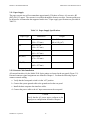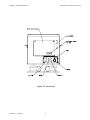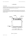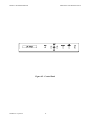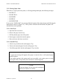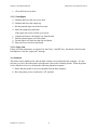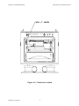
1
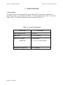
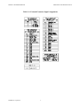
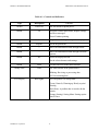
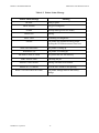
Model 2180 Series
Ruggedized Laser Printer
115 Vac
Table Top Mount
Operation and Maintenance Manual
DataMetrics Corporation
1717 Diplomacy Row
Orlando, Fl 32809
This manual is intended to function as an example ONLY and does not represent all configurations and options for this product.
Data Rights Provisions
THE INFORMATION CONTAINED IN THIS MANUAL IS SUPPLIED WITH LIMITED
RIGHTS ONLY. DATA SHALL NOT, WITHOUT THE WRITTEN PERMISSION OF THE
CONTRACTOR, BE EITHER (A) USED, RELEASED, OR DISCLOSED IN WHOLE OR IN
PART OUTSIDE THE GOVERNMENT, (B) USED IN WHOLE OR IN PART BY THE
GOVERNMENT FOR MANUFACTURE OR, IN THE CASE OF COMPUTER SOFTWARE
DOCUMENTATION, FOR PREPARING THE SAME OR SIMILAR COMPUTER
SOFTWARE, OR (C) USED BY A PARTY OTHER THAN THE GOVERNMENT, EXCEPT
FOR: (1) EMERGENCY REPAIR OR OVERHAUL WORK ONLY, BY OR FOR THE
GOVERNMENT, WHERE THE ITEM OR PROCESS CONCERNED IS NOT OTHERWISE
REASONABLY AVAILABLE TO ENABLE TIMELY PERFORMANCE OF THE WORK,
PROVIDED THAT THE RELEASE OR DISCLOSURE HEREOF OUTSIDE THE
GOVERNMENT SHALL BE MADE SUBJECT TO A PROHIBITION AGAINST FURTHER
USE, RELEASE OR DISCLOSURE; OR (2) RELEASE TO A FOREIGN GOVERNMENT, AS
THE INTEREST OF THE UNITED STATES MAY REQUIRE, ONLY FOR INFORMATION
OR EVALUATION WITHIN SUCH GOVERNMENT OR THE CONDITIONS OF (1) ABOVE.
THIS STATEMENT SHALL BE INCLUDED ON ANY REPRODUCTION HEREOF.
DataMetrics Corporation
1717 Diplomacy Row
Orlando, Fl 32809
Phone: (407) 251-4577
FAX: (407) 251-4588
[email protected]
MODEL 2180 SERIES PRINTER
OPERATION AND MAINTENANCE
Date
Revision
040308
–
DataMetrics Corporation
Description of Change
INITIAL RELEASE
i
MODEL 2180 SERIES PRINTER
OPERATION AND MAINTENANCE
Contents
1. CONFIGURATION .................................................................................................................... 1
1.1. Introduction ................................................................................................................................. 1
2. GENERAL INFORMATION .....................................................................................4
2.1. Scope ........................................................................................................................................... 4
2.2. Applicable Documents ................................................................................................................ 4
2.3. Printer Description ...................................................................................................................... 4
2.3.1. Power Subsystem ................................................................................................................. 4
2.3.2. Printing Subsystem............................................................................................................... 5
2.3.3. Control Console.................................................................................................................... 5
2.3.4. Cooling System .................................................................................................................... 5
2.3.5. External Interfaces............................................................................................................... 5
2.4. Specifications .............................................................................................................................. 5
2.5. Options ........................................................................................................................................ 5
2.5.1. Memory ................................................................................................................................ 6
2.5.2. PostScript Level 2 ................................................................................................................ 6
2.6. Supplementary Documentation ................................................................................................... 6
2.7. Introduction ................................................................................................................................. 7
2.8. Chassis Installation Configuration .............................................................................................. 7
2.9. Unpacking ................................................................................................................................... 7
2.10. Drum Unit Assy Installation ..................................................................................................... 7
2.11. Paper Supply ........................................................................................................................... 10
2.12. External Cable Installation ...................................................................................................... 10
2.13. Software Installation ............................................................................................................... 11
2.14. Limited Operation, Storage, and Transportation..................................................................... 11
3. OPERATION ............................................................................................................13
3.1. Introduction ............................................................................................................................... 13
3.2. Controls and Indicators ............................................................................................................. 13
3.3. Control Panel Menus ................................................................................................................. 17
3.3.1. Paper Tray Nomenclature................................................................................................... 17
3.3.2. Modes ................................................................................................................................. 17
3.3.3. Emulation Modes ............................................................................................................... 17
3.3.4. List of Factory Settings ...................................................................................................... 17
3.4. Normal Operation...................................................................................................................... 18
3.4.1. Printing from Tray 1........................................................................................................... 18
3.4.2. Manual Paper Feeding ...................................................................................................... 19
3.4.3. Stopping a Print Job ........................................................................................................... 19
3.5. LCD Messages .......................................................................................................................... 19
3.5.1. Clearing Paper Jams ........................................................................................................... 20
3.5.1.1. Jam Tray 1................................................................................................................... 20
3.5.1.2. Jam MP Tray ............................................................................................................... 20
3.5.1.3. Jam Inside.................................................................................................................... 22
3.5.1.4. Jam Rear ...................................................................................................................... 22
3.5.1.5. Jam Duplexer............................................................................................................... 23
3.5.1.6. Paper Jam .................................................................................................................... 23
3.6. Shutdown................................................................................................................................... 23
DataMetrics Corporation
ii
MODEL 2180 SERIES PRINTER
OPERATION AND MAINTENANCE
4. FUNCTIONAL DESCRIPTION ..............................................................................24
4.1. Introduction ............................................................................................................................... 24
4.2. Printer Description ................................................................................................................... 24
4.2.1. Power Distribution ............................................................................................................. 24
4.2.2. Paper Movement ................................................................................................................ 24
4.2.3. Control Console.................................................................................................................. 24
4.2.4 Cooling ............................................................................................................................... 24
5. MAINTENANCE…………………………………………………………………..26
5.1. Introduction ............................................................................................................................... 26
5.2. Tools and Test Equipment......................................................................................................... 26
5.3. Routine Maintenance................................................................................................................. 26
5.3.1. Replacing the Consumables ............................................................................................... 26
5.3.2. Replacing Maintenance Parts ............................................................................................. 26
5.5.3. Cleaning ............................................................................................................................. 26
5.3.3.1. Cleaning the Printer Interior........................................................................................ 26
5.3.3.2. Cleaning the Corona Wire........................................................................................... 27
5.4. Replaceable Components and Subassemblies....................................................................... 28
5.4.1. Toner Cartridge Replacement ......................................................................................... 28
5.4.2. Control Panel Replacement ............................................................................................. 29
6. SETTINGS...................................................................................................................................30
6.1. Introduction............................................................................................................................... 30
6.2. Changing Factory Settings .................................................................................................... 30
6.2.1. Connector Location ............................................................................................................ 30
6.2.2. Pictorial Representation ..................................................................................................... 30
6.2.3. Connector Settings ............................................................................................................. 30
DataMetrics Corporation
iii
MODEL 2180 SERIES PRINTER
OPERATION AND MAINTENANCE
Figures
Figure 3-1. Installation Dimensions ...................................................................................................... 9
Figure 3-2. Rear Panel......................................................................................................................... 12
Figure 4-1. Front Panel........................................................................................................................ 13
Figure 4-2. Control Console................................................................................................................ 14
Figure 4-3. Paper Jam Areas ............................................................................................................... 21
Figure 5-1. Chassis Interconnections .................................................................................................. 25
Figure 6-1. Connector Location .......................................................................................................... 31
Figure 6-2. Jumper Setting Definitions ............................................................................................... 32
Tables
Table 1-1.
Table 1-2.
Table 1-3.
Table 1-4.
System Configuration .......................................................................................................... 1
Field Replaceable Units ....................................................................................................... 2
External Cables .................................................................................................................... 2
External Connector Signal Assignments ............................................................................. 3
Table 2-1. Physical Specifications ........................................................................................................ 6
Table 2-2. Electrical Specifications ...................................................................................................... 6
Table 2-3. Environmental Specifications .............................................................................................. 6
Table 3-1. Paper Supply Specifications .............................................................................................. 10
Table 4-1. Controls and Indicators...................................................................................................... 15
Table 4-2. Printer Status Indications During Normal Operation ........................................................ 16
Table 6-1. Factory Settings……………………………………..……………………………………30
Table 6-2. Jumper Settings………..…………………………………………………………………33
DataMetrics Corporation
iv
MODEL 2180 SERIES PRINTER
OPERATION AND MAINTENANCE
1. CONFIGURATION
1.1. Introduction
This chapter defines the configuration of a specific Model 2180 Series printer. Information is
provided concerning system configuration (Table 1-1), field-replaceable units (Table 1-2), external
cabling (Table 1-3), and external connector signal assignments (Table 1-4).
Table 1-1. System Configuration
Characteristic
Description
Top Assembly Part No.
117065-103
Input Power
115 VAC 50/60 Hz
Memory, No Options
32 Mb Standard
1 DIMM Slot
Installation Configuration
DataMetrics Corporation
16, 32, 64 or 128 Mb Optional
Table Top Mount
1
MODEL 2180 SERIES PRINTER
OPERATION AND MAINTENANCE
Table 1-2. Field Replaceable Units
Description
Part No.
Quantity
Per Chassis
Toner Cartridge
1
Drum Unit
1
Paper Cassette
1
Control Panel Assembly
1
Table 1-3. External Cables
Function
Part No.
Power Input Connector
DataMetrics Corporation
2
MODEL 2180 SERIES PRINTER
OPERATION AND MAINTENANCE
Table 1-4. External Connector Signal Assignments
DataMetrics Corporation
3
MODEL 2180 SERIES PRINTER
OPERATION AND MAINTENANCE
2. GENERAL INFORMATION
2.1. Scope
This manual provides information and instructions required for the operation and maintenance of the
Model 2180 Series printer manufactured by DataMetrics Corporation.
2.2. Applicable Documents
Military Standards
MIL-STD-461e
Electromagnetic Emission and Susceptibility Requirements
for the Control of Electromagnetic Interference
Commercial Standards
IEEE-1284B
Standard Signaling Method, Bi-directional Parallel
Peripheral Interface
RS-232C
Serial Communication Protocol
10Base2
Ethernet (IEEE 802.3)
Brother
Brother Laser Printer HL 1800 Series
2.3. Printer Description
The Model 2180 Series printer is a ruggedized, general-purpose laser printer that is configured in a
single enclosure. The equipment is packaged using environmental management techniques that
protect internal components from shock, vibration, temperature extremes, and EMI/RFI. The chassis
is configured for tabletop mount operation. The printer includes the following primary functional
elements:
• Power subsystem
• Printing subsystem
• Control Panel
• Cooling system
• External interfaces
2.3.1. Power Subsystem
The Model 2180 Series printer operates with 115 VAC input power. The power subsystem includes
an EMI filter, fuses, and power switch. DC voltages required for various printer functions are
generated within the commercial print engine.
DataMetrics Corporation
4
MODEL 2180 SERIES PRINTER
OPERATION AND MAINTENANCE
2.3.2. Printing Subsystem
The Model 2180 Series printer incorporates a Brother HL 1800 print engine that provides 300 dpi,
600 dpi and Brother HQ1200 technology, which provides the best print quality while printing at full
speed of 19 pages per minute. A toner saver mode and improved gray printing is also provided for
within the printer. The printer formatter includes a Motorola RISC-based formatter and 32 Mb
memory, which is expandable to 144 Mb. Memory Enhancement Technology (MEt) automatically
compresses data, which allows printing of images that are more complex than available memory
would normally permit.
The printer may be operated with any host computer that supports Windows 95/98 Me, 2000, NT 4.0,
XP, Macintosh OS 8.6-9.2 and 1 X 10.1. The printer supports the PCL6 printer language, which
includes 45 scalable TrueType fonts and one bitmapped line printer font. Built-in HP-GL/2 vector
graphics are included to produce up to 128 shades of gray. The printer supports HP PostScript, Level
3, with 35 built-in PostScript language fonts. The printer automatically detects and switches to the
appropriate language for the print job.
The printer automatically loads Letter, A4, Executive, B5, or Legal paper from the 250-sheet cassette.
The toner cartridge will support printing of 6,500 A4/Letter single-sided pages at 5% coverage.
2.3.3. Control Panel
The control panel is located on the center of the printer front panel. This control panel is the operator
interface for print operations other than those controlled from the host computer. Controls and
indicators are described in Chapter 4.
2.3.4. Cooling System
The ruggedized Model 2180 Series printer utilizes the cooling mechanism of the commercial print
engine. Three fans are used to cool the print engine and are part of the print engine.
2.3.5. External Interfaces
The rear panel of the printer includes connectors for prime power and the host computer data
interfaces. The standard printer configuration incorporates a Parallel IEEE-1284B bi-directional
DB25, a Serial RS-232C DB25, and tri-axial 10Base2 Ethernet interfaces. An unused Ethernet
connection (J4 or J5) must be terminated with a 50Ω termination for proper operation.
The printer auto-detects print requests on any one of these interfaces, and prints from that port on a
first come first serve basis. A chassis ground lug is located on the rear panel adjacent to the power
connector and two fuse holders, F1 and F2, for current overload protection. Spare fuses are located
on the inside of the hinged rear panel.
2.4. Specifications
Equipment specifications for the Model 2180 Series printer are defined in Tables 2-1 through 2-3.
2.5. Options
The Model 2180 Series printer may be configured with the optional features listed in the following
paragraphs. Options included in a delivered configuration are defined as follows.
DataMetrics Corporation
5
MODEL 2180 SERIES PRINTER
OPERATION AND MAINTENANCE
2.5.1. Memory
The printer includes provisions for one memory expansion module. The base system includes 32Mb
memory, which can be expanded to a total of 144Mb. Memory modules are available in 16Mb,
32Mb, 64Mb and 128Mb configurations.
2.5.2. PostScript Level 2
The printer is equipped with HP PostScript Level 2 printer language emulation with 35 built-in
PostScript language fonts and 8 Mb RAM.
2.6. Supplementary Documentation
Supplementary information pertaining to the commercial hardware and software that forms a part of
the Model 2180 Series printer is provided in the Brother Laser Printer HL-1800 series User’s Guide.
Table 2-1. Physical Specifications
Characteristic
Description
Dimensions
See Figure 3-1.
Weight
50 LB max
Table 2-2. Electrical Specifications
Characteristic
Description
Input Voltage
115 VAC input or
100-120 VAC, single-phase, 50/60 Hz
Table 2-3. Environmental Specifications
DataMetrics Corporation
6
MODEL 2180 SERIES PRINTER
OPERATION AND MAINTENANCE
Characteristic
Description
Temperature
Operating
0 to 55oC
Non-operating
-40 to 70oC
Relative humidity (non-condensing)
10 to 90%
Altitude
Operating
15,000 ft
Non-operating
50,000 ft
Random vibration (non-operating)
0.01 g2/Hz at 10 to 2,000 Hz
Shock (non-operating)
20 g, 11 ms
Acoustic noise
< 50 dBA at 1 m
EMI/EMC
MIL-STD-461, Methods CE03, CS01, CS02,
CS06, RE02, RS02, and RS03.
Fungus
No fungus-nutrient materials
2.7. Introduction
This chapter provides information and instructions required for installation of the Model 2180 Series
printer. Information is included concerning chassis installation configuration, unpacking, toner
cartridge installation, paper supply provisions, connecting of external cabling, software installation,
and storage.
2.8. Chassis Installation Configuration
The Model 2180 Series printer is shock isolated tabletop mounting configuration. Chassis
dimensions applicable to the installation environment are identified in Figure 3-1.
2.9. Unpacking
Follow the steps listed below to unpack the Model 2180 Series printer and prepare the unit for
installation. Packing materials should be retained for future use.
a. Carefully remove the printer from the shipping container. Inspect the unit for any evidence of
damage.
b. Open the paper cassette tray access door located on the front of the unit. Slide the paper tray
out of the printer and remove the shipping retainer, if any, from the tray.
2.10. Drum Unit Assembly Installation
The Model 2180 Series printer is shipped without the toner cartridge and drum unit installed. Follow
DataMetrics Corporation
7
MODEL 2180 SERIES PRINTER
OPERATION AND MAINTENANCE
the procedure defined below to install the cartridge.
a. Remove the toner cartridge from its packaging. Gently rock it from side to side five or six
times.
Caution
To prevent damage, do not expose the cartridge to
light for more than a few minutes.
b. Remove the protective cover from the toner cartridge.
c. Install the toner cartridge into the drum unit.
d. Open the front door of the printer and remove the top cover.
e. Unfasten and remove the drum unit assembly retainer located on the top of the print engine.
f. Pull the drive locking mechanism forward into the locking position, green handle, located on
the left side of the print engine.
g. Unfasten and lower the multi-purpose tray.
h. Insert the drum unit assembly into the print-engine.
i. Release the drive locking mechanism to its original locking position.
j. Raise the multi-purpose tray and fasten.
k. Replace and fasten the drum unit assembly retainer located on the top of the print engine.
l. Replace the top cover and close the front access door.
DataMetrics Corporation
8
MODEL 2180 SERIES PRINTER
OPERATION AND MAINTENANCE
Figure 3-1. Installation Dimensions
DataMetrics Corporation
9
MODEL 2180 SERIES PRINTER
OPERATION AND MAINTENANCE
2.11. Paper Supply
The paper cassette tray will accommodate approximately 250 sheets of letter, A4, executive, B5
(ISO), B5 (J15) paper. The cassette is accessible through the front access door. Cassette guides may
be adjusted to accommodate the supported media sizes. Paper supply specifications are provided in
Table 3-1.
Table 3-1. Paper Supply Specifications
Paper Type
Dimensions
Letter
8.5 x 11 in.
(216 x 279 mm)
A4
8.3 x 11.7 in.
(210 x 297 mm)
Executive
7.3 x 10.5 in.
(191 x 267 mm)
B5 (ISO)
6.9 x 9.9 in.
(176 x 250 mm)
B5 (JIS)
7.2 x 10 in.
(182 x 257 mm)
Weight
16 to 28 lb
(60 to 105 g/m2)
2.12. External Cable Installation
All external interfaces for the Model 2180 Series printer are located at the rear panel (Figure 3-2).
External connector signal assignments are defined in Chapter 1. Perform the following steps to
connect external cabling.
a. Verify that the front panel switch is in the “off” position.
b. Connect the system ground cable to the ground stud on the rear panel.
c. Install the host computer data interface cables.
d. Connect the power cable to the AC input connector on the rear panel.
Caution
Verify that the AC power source conforms to the
input power configuration defined in Chapter 1.
DataMetrics Corporation
10
MODEL 2180 SERIES PRINTER
OPERATION AND MAINTENANCE
2.13. Software Installation
Install the software from CD-ROM that is supplied with Model 2180 printer. Refer to the Brother
Laser Printer HL-1800 series User’s Guide.
2.14. Limited Operation, Storage, and Transportation
If the printer is not operated for more than 1 week, the toner cartridge should be removed and stored
in a humidity-controlled environment. This provision is particularly important when the equipment is
used in a high-humidity environment. If the printer is to be stored or transported, the unit should be
packaged as originally shipped. The printer can be stored or transported in any manner that is
consistent with the environmental conditions identified in Table 2-3.
DataMetrics Corporation
11
MODEL 2180 SERIES PRINTER
OPERATION AND MAINTENANCE
Figure 3-2. Rear Panel
DataMetrics Corporation
12
MODEL 2180 SERIES PRINTER
OPERATION AND MAINTENANCE
3. OPERATION
3.1. Introduction
This chapter provides information concerning printer controls and indicators, test printing, normal
operation, error conditions, and shutdown. Before the unit is powered up for the first time, verify that
the installation procedures defined in Chapter 3 have been performed.
3.2. Controls and Indicators
All controls and indicators required for operation of the Model 2180 Series printer are located at the
front panel of the unit (Figure 4-1). Control panel switches and indicators are shown in Figure 4-2.
Controls and indicators are described in Table 4-1. Printer status indications for normal operation are
identified in Table 4-2.
Figure 4-1. Front Panel
DataMetrics Corporation
13
MODEL 2180 SERIES PRINTER
OPERATION AND MAINTENANCE
Figure 4-2. Control Panel
DataMetrics Corporation
14
MODEL 2180 SERIES PRINTER
OPERATION AND MAINTENANCE
Table 4-1. Controls and Indicators
Type
Description
Switch
Power On
Button
Go
Function
On/ off switch for prime power.
Exit from Control panel menu, Reprint settings
and Error messages.
Pause/Continue printing.
Button
Job Cancel
Stop and cancel the printer operation in progress.
Button
Reprint
Button
+
Move forward and backward through menus.
Button
-
Move forward and backward through selectable
options.
Button
Set
Set the Reprint menu.
Select the displayed menu.
Set the selected menus and settings.
Button
Back
Go back one level in the menu structure.
Orange LED
Data
On: Data remains in the printer buffer.
Blinking: Receiving or processing data.
Off: No remaining data.
LCD Display
Back lights
Off: The printer is in Sleep status.
Green (General): Warming up/ Ready to print/
Printing.
Red (Error): A problem has occurred with the
printer.
Orange (Setting): Setting Menu/ Setting reprint
times/ Pause.
DataMetrics Corporation
15
MODEL 2180 SERIES PRINTER
OPERATION AND MAINTENANCE
Table 4-2. Printer Status Message
Printer Status Message
READY
PROCESSING
SLEEP
Meaning
Ready to print.
Busy processing data.
In Sleep status (power save mode)
PRINTING
Printing.
SELF TEST
Performing self-diagnostic.
PAUSE
NOW INITIALIZING
WARMING UP
MEMORY SIZE=XX MB
JOB CANCELLING
The printer has suspended feeding forms.
Pressing the GO button resumes form feed.
The printer is setting up.
The printer is warming up.
This printer has XX MB memory.
Canceling the job.
RESOLUTION ADAPT
Printing with reduced resolution.
PRESS SET TO PRINT
Press the SET button to start printing.
RESET TO FACTORY SETTING
DataMetrics Corporation
The printer settings return to the factory
settings.
16
MODEL 2180 SERIES PRINTER
OPERATION AND MAINTENANCE
3.3. Control Panel Menus
3.3.1. Paper Tray Nomenclature
The Model 2180 has been designed for usage of the two paper trays provided for with the Brother
Printer. Those trays are defined as follows and will appear on the LCD panel as shown below:
Tray
Description
Usage
Tray 1
Upper Paper Tray
Standard 250 sheet paper tray.
MP Tray
Multi-purpose Tray
Redesigned for single sheet feed.
Tray 2
Optional Lower Tray
Not available with current design.
3.3.2. Modes
There are 8 modes. For more information about the selections available for each mode, refer to the
Brother Laser Printer HL-1800 series User’s Guide supplementary documentation supplied with
printer.
•
Information
•
Paper
•
Quality
•
Setup
•
Print Menu
•
Network
•
Interface
•
Reset Menu
3.3.3 Emulation Modes
The printer has the following emulation modes. (see User’s Guide)
•
HP Laser Jet Mode
•
BR-Script 3 Mode
•
EPSON FX-850 and IBM Proprinter XL Mode
3.3.4 List of Factory Settings
For listing factory default settings refer to the Brother Laser Printer HL-1800 series User’s Guide
supplementary documentation.
DataMetrics Corporation
17
MODEL 2180 SERIES PRINTER
OPERATION AND MAINTENANCE
3.4. Normal Operation
Follow the instructions defined below to operate the printer under normal conditions.
a. Power-up the host computer.
b. Place the printer power switch in the “on” position.
c. Verify that the READY LED illuminates after completion of the self-test/warm-up sequence.
Once the printer has achieved a ready state, no manual intervention is required to conduct
routine print tasks. Operational parameters are not affected by normal power on/off cycles.
3.4.1. Printing from Tray 1
Specifications for paper cassette media are defined in Table 3-1. Follow the instructions defined
below to conduct print operations with Tray 1.
a. Open the front access door.
b. Pull the paper cassette completely out of the printer.
c. Adjust the paper guides at the right-hand side and back of the paper cassette to match the paper
size. Make sure that the tips of the paper guides fit into the slots co
Note
The 2180 printer is not designed for legal or 8.5 x
13 inch paper.
d. Position the paper into the paper cassette. Make sure that the paper is flat in the cassette at all
corners and below the limit mark
Note
Do not put more than 250 sheets of paper (80
g/m2 or 21 lb.) in the cassette or the paper may
jam. Paper can be loaded up to the lines on the
sliding guide.
e. Put the paper cassette back into the printer. Make sure it is completely in the printer.
f. Close the front access door
3.4.2. Manual Paper Feeding
Specifications for manual-feed media are defined in Table 3-1. Follow the instructions defined below
to conduct print operations with Multi-purpose tray.
a. Open the front access door.
b. Unlatch and lower the multi-purpose tray.
DataMetrics Corporation
18
MODEL 2180 SERIES PRINTER
OPERATION AND MAINTENANCE
c. Slide the paper guides slightly wider than the media.
d. Position the media in the center of the paper guides with the print side up.
e. Move the media into the manual-feed entry point of the print engine.
f. Verify that operational software is configured for manual feed.
g. Initiate the print job. If the “manual feed pause” option is selected with the operational
software, printing of individual pages is initiated by pressing the front panel GO switch.
Note
If you place paper in the Multi-purpose Tray and
the MANUAL FEED=ON has been set in the
PAPER mode from the control panel, the printer
will load paper only from the Multi-purpose
Tray.
h. When manual feed operations are complete, raise and secure the front panel door.
3.4.3. Stopping a Print Job
A print job can be terminated from the application software, from a print queue, or by pressing the
Job Cancel button. The display shows “JOB CANCELLING” until canceling is completed.
After canceling the job, the printer returns to the “READY” state.
When the printer is in any state except receiving data or printing, the display shows “NO DATA !!!”
And cannot cancel the job.
3.5. LCD Messages
When the printer incurs error and maintenance messages refer to Chapter 6 of the Brother Laser
Printer HL 2180 series manual that is provided for as part of this manual.
DataMetrics Corporation
19
MODEL 2180 SERIES PRINTER
OPERATION AND MAINTENANCE
3.5.1. Clearing Paper Jams
When there is a paper jam in the printer, it will stop printing and display the following messages:
• JAM TRAY1
• JAM MP TRAY
• JAM INSIDE
• JAM REAR
• JAM DUPLEXER
If you see the “PAPER JAM” error message find the location of the jammed paper and following the
instructions to remove it (Figure 4-3). After you have followed the instructions, the printer will
automatically resume printing.
3.5.1.1. Jam Tray1
a. Open the front access door.
b. Remove the paper cassette tray.
c. Pull the jammed paper out of the printer.
d. Put the paper cassette back into the printer.
e. Raise and secure the front access door.
3.5.1.2. Jam MP Tray
a. Remove any media from the multi-purpose Tray.
b. Remove the jammed paper from the multi-purpose Tray.
c. Put all the paper back into the multi-purpose Tray correctly.
Note
If a paper jam message still appears after paper is removed, there is still jammed paper
inside the printer.
If torn media remains in the printer and is not accessible, cycle printer power to rotate
print engine rollers. Reopen the printer and remove media fragments.
Caution
To prevent damage, do not expose the cartridge to
light for more than a few minutes.
DataMetrics Corporation
20
MODEL 2180 SERIES PRINTER
OPERATION AND MAINTENANCE
Figure 4-3. Paper Jam Area
DataMetrics Corporation
21
MODEL 2180 SERIES PRINTER
OPERATION AND MAINTENANCE
3.5.1.3. Jam Inside
a. Open the front access door and remove the top cover.
b. Unfasten and remove the drum unit assembly retainer located at the top of the print engine.
c. Unfasten and lower the multi-purpose tray.
d. Pull the drive locking mechanism forward into the locking position, green handle, located on
the left side of the print engine.
e. Remove the drum unit assembly from the print engine.
f. Pull the jammed paper out of the paper cassette/fuser unit.
g. Replace the drum unit assembly into the printer-engine.
h. Replace and fasten the drum unit assembly retainer.
i. Release the drive locking mechanism to its original locking position.
j. Raise the multi-purpose tray and fasten.
k. Replace the top cover and close the front access door.
3.5.1.4. Jam Rear
a. Open the front access door and remove the top cover.
b. Unfasten and remove the drum unit assembly retainer located on the top of the print engine.
c. Unfasten and lower the multi-purpose tray
d. Pull the drive locking mechanism forward into the locking position, green handle, located on
the left side of the print engine.
e. Remove the drum unit assembly from the print-engine.
f. Pull the jammed paper out of paper cassette/fuser unit.
If the paper jam can be cleared, go to step k.
g. Open the rear access door.
h. Unfasten and lower the output tray
i. Open the Jam Clear Cover and pull the jammed paper out of the fuser unit.
j. Close the Jam Clear Cover and raise the output tray and fasten.
k. Replace the drum unit assembly into the printer-engine
l. Replace and fasten the drum unit assembly retainer.
m. Release the drive locking mechanism (green handle) to its original locking position.
n. Raise the multi-purpose tray and fasten.
DataMetrics Corporation
22
MODEL 2180 SERIES PRINTER
OPERATION AND MAINTENANCE
o. Close the front access door.
3.5.1.5. Jam Duplex
a. Unfasten and lower the rear access door.
b. Unfasten and lower the output tray.
c. Pull the jammed paper out of the fuser unit.
d. Raise the output tray and fasten.
If the paper jam can be cleared, go to step h.
e.
f.
g.
h.
Unfasten and remove the duplex tray from the unit.
Pull the jammed paper out of the printer.
Put the duplex tray back into the unit and fasten.
Raise the rear access door and fasten.
3.5.1.6. Paper Jam
Follow all of the instructions, as required, for Jam Tray1, Jam MP Tray, Jam Inside, Jam Rear and
Jam Duplex to clear the “paper jam” message.
3.6. Shutdown
The printer enters standby mode when no data is being received from the host computer. It is not
necessary to power down the printer when the unit is not used for limited periods. When the printer
is to be taken out of service, perform the following shutdown sequence:
a. Ensure that the printer is not receiving data from the host computer.
b. Place the printer power switch in the “off” position.
DataMetrics Corporation
23
MODEL 2180 SERIES PRINTER
OPERATION AND MAINTENANCE
4. FUNCTIONAL DESCRIPTION
4.1. Introduction
This chapter describes the major functional elements of the Model 2180 Series printer. Information
is provided concerning power distribution, the printing subsystem, control console, and cooling
system. Chassis interconnections are identified in Figure 5-1.
4.2. Printer Description
The Model 2180 Series printer provides laser hardcopy output of data received from a host computer.
The standard printer configuration incorporates an IEEE-1284B bi-directional parallel interface
(Centronics). The unit may be configured with optional 10base-T Ethernet. The mechanical and
electrical subsystems of the printer are described in the following paragraphs.
4.2.1. Power Distribution
The Model 2180 Series printer utilizes the 115Vac primary power subsystem of the commercial print
engine. Prime power enters the chassis at the rear panel J1 connector. 115Vac power is sent through
an EMI filter that provides attenuation of interference related to input voltage and output current.
Prime power exits the filter and is routed to two 15-ampere fuses and then to the power switch at the
front panel. The load side of the power switch provides AC power to the print engine input-power
connector. A chassis ground stud is located on the rear panel of the unit.
4.2.2. Paper Movement
The paper feed system automatically picks print media from either Tray 1 or MP TRAY and delivers
it to the registration roller. Before the media reaches the registration roller, the separation pad
separates any excess sheets of media and the registration shutter corrects the media’s skew.
A top-of-page sensor detects the leading edge of the page. The paper is synchronized to the leading
edge of the image on the photosensitive drum and transferred to the paper. After the transferring
stage of the image formation process, the paper is fed to the fusing assembly and fused.
The paper exits the printer through the top or rear output bins.
4.2.3. Control Console
All controls required for printer operation are located at the front panel of the unit. The control panel
includes the GO, JOB CANCEL, REPRINT, +, -, SET and BACK switches. The control panel LCD
displays the printer status. The power switch turns the printer power on/off. Printer controls and
indicators are described in Chapter 3.
4.2.4. Cooling
The ruggedized Model 2180 Series printer utilizes the cooling mechanism of the commercial print
engine. Cooling air is circulated in the unit by 3 fans located on the print engine. The fans are
powered by the printer’s dc power subsystem. Air is forced across print engine components and
exhausted at the top of the chassis. The printer has a nominal power dissipation of less than 410
watts during printing, less than 70 watts standby mode and less than 10 watts sleep mode.
DataMetrics Corporation
24
MODEL 2180 SERIES PRINTER
OPERATION AND MAINTENANCE
Figure 5-1. Chassis Interconnection
DataMetrics Corporation
25
MODEL 2180 SERIES PRINTER
OPERATION AND MAINTENANCE
5. MAINTENANCE
5.1. Introduction
This chapter provides information and instructions concerning Model 2180 Series printer tools and
test equipment, routine maintenance, fault isolation, and the removal and installation of replaceable
components and subassemblies.
5.2. Tools and Test Equipment
The following tools and test equipment are required to maintain the printer:
•
Common hand tools
•
TORX #10 screwdriver
•
Digital voltmeter
•
Host computer with compatible data interface
5.3. Routine Maintenance
5.3.1. Replacing the Consumables
Normal print operations require consumables to be replaced regularly. The following messages will
appear on the LCD panel.
•
TONER LOW
•
TONER EMPTY
•
CHANGE DRUM SOON
Refer to the Brother Laser Printer HL-1800 series User’s Guide supplemental documentation.
5.3.2. Replacing Maintenance Parts
Replacement of maintenance parts to maintain print quality will cause the following messages will
appear on the LCD panel.
•
REPLACE FUSER
•
REPLACE PF KIT
•
REPLACE LASER
Refer to the Brother Laser Printer HL-1800 series User’s Guide supplemental documentation.
5.3.3. Cleaning
5.3.3.1 Cleaning the Printer Interior
Cleaning the printer interior for if printouts are stained with toner.
a.
Open the front access door and remove the top cover.
b.
Unfasten and remove the drum unit assembly retainer located at the top of the print engine.
DataMetrics Corporation
26
MODEL 2180 SERIES PRINTER
OPERATION AND MAINTENANCE
c. Unfasten and lower the multi-purpose tray.
d. Pull the drive locking mechanism forward into the locking position, green handle, located on
the left side of the print engine.
e. Remove the drum unit assembly from the print engine.
f. Gently wipe the scanner window with a soft dry cloth.
g. Replace the drum unit assembly into the printer-engine.
h. Replace and fasten the drum unit assembly retainer.
i. Release the drive locking mechanism to its original locking position.
j. Raise the multi-purpose tray and fasten.
k. Replace the top cover and close the front access door.
5.3.3.2 Cleaning the Corona Wire
Cleaning the printer interior for if printouts are stained with toner.
a. Open the front access door and remove the top cover.
b. Unfasten and remove the drum unit assembly retainer located at the top of the print engine.
c. Unfasten and lower the multi-purpose tray.
d. Pull the drive locking mechanism forward into the locking position, green handle, located on
the left side of the print engine.
e. Remove the drum unit assembly from the print engine.
f. Slide the blue tab that is located on the drum unit assembly from right to left several times.
Return the tab to the Home position.
g. Replace the drum unit assembly into the printer-engine.
h. Replace and fasten the drum unit assembly retainer.
i. Release the drive locking mechanism to its original locking position.
j. Raise the multi-purpose tray and fasten.
k.
Replace the top cover and close the front access door.
DataMetrics Corporation
27
MODEL 2180 SERIES PRINTER
OPERATION AND MAINTENANCE
WARNING
POTENTIALLY LETHAL VOLTAGES EXIST WITHIN THE PRINTER. SERIOUS
INJURY MAY RESULT IF SAFETY PRECAUTIONS ARE NOT OBSERVED.
FAULT DIAGNOSIS PROCEDURES REQUIRE THAT INTERNAL COMPONENTS
BE TESTED WHEN PRIME POWER IS APPLIED. THESE COMPONENTS MUST
ONLY BE TOUCHED WITH THE APPROPRIATE TEST EQUIPMENT.
5.4. Replaceable Components and Sub assemblies
The following paragraphs include information concerning replaceable components and
subassemblies. The following items are replaceable within an organizational-level maintenance
activity:
• Toner Cartridge
• Paper Cassette Tray
• Control Panel
WARNING
POTENTIALLY LETHAL VOLTAGES EXIST WITHIN THE PRINTER. SERIOUS
INJURY MAY RESULT IF SAFETY PRECAUTIONS ARE NOT OBSERVED.
DISCONNECT THE POWER SOURCE BEFORE PERFORMING REPAIR
PROCEDURES.
Note
Observe precautions relating to electrostatic discharge (ESD) when handling components
that include integrated circuitry.
5.4.1. Toner Cartridge Replacement
Removal:
a. Open the top cover of the printer.
b. Unfasten the toner cartridge retainer.
c. Pull the toner cartridge toward the front panel and remove the cartridge from the chassis.
Installation:
a. Remove the new toner cartridge from the packaging material.
b. Gently shake the cartridge to evenly distribute the toner.
c. Remove the sealing tape from the cartridge.
d. Insert the cartridge in the print-engine carriage in the direction of the arrows provided on the
DataMetrics Corporation
28
MODEL 2180 SERIES PRINTER
OPERATION AND MAINTENANCE
cartridge. Move the cartridge into the guides until it stops securely in the printer.
e. Fasten the toner cartridge retainer.
f. Close and secure the top cover of the printer.
5.4.2. Control Panel Replacement
Removal:
a. Open the top cover of the printer.
b. Disconnect the control panel harnesses.
c. Remove the six nuts that secure the control panel to the inside of the front panel.
d. Remove the control panel from the inside of the front panel.
Installation:
a. Position the control panel on the front of the chassis.
b. Install the hardware that secures the control panel to the front panel.
c. Connect the control panel harness.
d. Close and secure the top cover of the printer.
.
DataMetrics Corporation
29
MODEL 2180 SERIES PRINTER
OPERATION AND MAINTENANCE
6. SETTINGS
6.1. Introduction
This chapter defines the communications parameters for the Model 2180 Series printer, baud rate,
handshake, data and stop bits, parity and conversion direction. The printer parameters are set at the
factory and are shown in Table 6-1.
Table 6-1. Factory Settings
Communication Parameters
Factory Settings
Baud Rate
9600
Handshake
XON/XOFF
Data and Stop Bits
8,1
Parity
Parity Inhibit
6.2. Changing Factory Settings
The following paragraphs include information concerning location of the connector that allows
factory settings to be changed, a pictorial representation showing jumper settings on the connector
and table showing settings.
6.2.1. Connector Location
Located on the front face of the print engine, behind the front access door, is the connector where all
factory settings are set and can be changed (Figure 6-1.). The connector is hard wired from the RS232
centronics converter that is located underneath the print engine. This allows factory settings to be
changed with out having to disassemble the entire engine to make changes to the factory settings.
6.2.2. Pictorial Representation
A pictorial representation of the connector showing jumper settings locations is shown in Figure 6-2.
6.2.3. Jumper Settings
Changing of the factory settings can be accomplished by moving and or adding jumpers to the
connector. For setting definition refer to Table 6-2.
DataMetrics Corporation
30
MODEL 2180 SERIES PRINTER
OPERATION AND MAINTENANCE
Figure 6-1. Connector Location
DataMetrics Corporation
31
MODEL 2180 SERIES PRINTER
OPERATION AND MAINTENANCE
Figure 6-2. Jumper Setting Definitions
DataMetrics Corporation
32
MODEL 2180 SERIES PRINTER
OPERATION AND MAINTENANCE
Table 6-2. Jumper Settings
DataMetrics Corporation
33