1
FM-2721
MARINE VHF RADIOTELEPHONE
(Elemental Chlorine Free)
The paper used in this manual
is elemental chlorine free.
C
FURUNO Authorized Distributor Dealer
9-52, Ashihara-cho,
Nishinomiya, Japan
Te l e p h o n e :
Fax:
+ 8 1 - ( 0 ) 7 9 8 - 6 5 - 2 111
+81-(0)798-65-4200
All rights reserved.
Printed in Japan
PUB. No. OME-56163
(HIMA)
FM-2721
FIRST
EDITION
F
:
:
MAR. 2000
APR 27, 2005
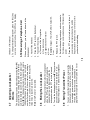
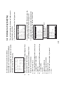
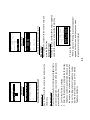
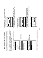
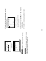
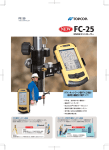
4. The equipment displays “Wait for Ack Auto re-Xmit”
while waiting for acknowledgment of the distress
call. (Transmitting repeats with 3.5 to 4.5 minutes
interval until pressing [Cancel] key.
Distress call
in progress
DISTRESS CALL
Nature:
UNDESIGNATED
Pos:
12:34
12˚34E123˚45N
3. Open the DISTRESS button lid in the hanger and
press the [DISTRESS] button about three seconds
to show the following display, then release the
button.
2. Press the [POWER] switch in the hanger to turn on
the unit if it is not already on.
1. Hook off the handset.
Do the following when a life endangering situation
arises on your vessel:
i
Note: When transmitting DISTRESS, the equipment
goes into the distress mode, which allows the operator
to use the handset connected to either REMOTE 1 or 2
port if it is hooked on or off.
To escape from the distress mode, turn the power off
and on again.
5. When you receive the distress acknowledgement
call, you are automatically connected to CH16.
Hook off the handset if it is not already off hook.
Press the PTT switch and say:
a) MAYDAY three times.
b) This is [name of your vessel].
c) MAYDAY
d) This is [name of your vessel].
e) Position
f) Nature of Distress
g) Kind of assistance needed
h) Number of crew
i) Other info such as description of your vessel
j) Over.
DISTRESS Call Procedure
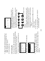
ii
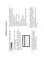
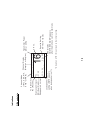
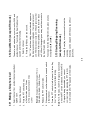
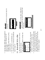
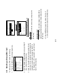
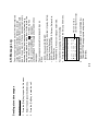
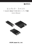
When receiving a distress alert, the LCD display appears as shown right.
The DIST ACK by voice can be transmitted by you under certain conditions. Please
carefully read and follow the flow chart to determine whether you should transmit it or
not.
If you do not receive the DIST ACK signal, follow the flow chart shown on the next page.
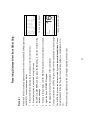
6. Be prepared to follow the instructions of the coast station.
5. Open the Rcvd. DISTRESS file again.
4. Wait up to three minutes until the DIST ACK signal from a coast station is received.
3. Select Rcvd. DISTRESS, and then press the [Enter] key to view the contents of the
distress message.
2. Press the [Log] key to show the Sel. Log file menu.
1. Silence the alarm by pressing the [Cancel] key (or wait for two minutes).
When the FM-2721 receives a distress alert from other vessel the LED (Red) lights and
the FM-2721 sounds the distress alarm.
General
Receiving Distress Alert from Other Ship
25W
16
SIMP
<Hand set off hook>
VOL:08
SQ:03
RCVD. DISTRESS
Rx
SCAN
INTL
<Hand set on hook>
INTL
SIMP
25W
Rx
16
Lat: 45.23 N
Lon:121.88 E
Time:10:57UTC
VOL:08
SQ:03
RCVD. DISTRESS
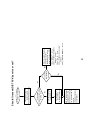
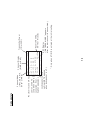
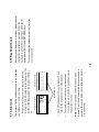
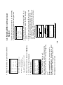
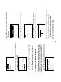
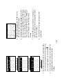
Continue watch on
CH 16 until you hear
[SEELONCE FINI],
which means completion of distress communication.
(Follow instructions of
coast station.)
Successively to
check receive
message contents.
Press the [Cancel] key
to silence alarm.
Yes
Acknowledge
received from coast station?
(Wait 3 mins.)
Press the [Cancel] key
to silence alarm.
Read DISTRESS message.
Distress alert received.
No
No
Is
your vessel
near vessel in
distress?
Yes
iii
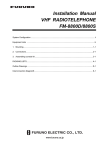
1. Say "MAYDAY" ... Once
2. Say ID number of vessel in
distress ... 3 times
3. Say "This is" ... Once
4. Say ID number of your vessel
... 3 times
5. Say "Received MAYDAY" ... Once
If you can assist the vessel
in distress, transmit
acknowledge by voice to
vessel in distress on CH 16.
Should I transmit DIST ACK by voice or not?
Rough handling may affect its
watertight integrity.
Only qualified personal should work
inside the equipment.
Improper repair work can cause
electrical shock or fire.
Any repair work must be done by a
licensed radio technician.
Continued use of the equipment can
cause fire or electrical shock.
Turn off the power immediately if
waterleaks into the equipment or the
equip-ment is emmitting smoke or
fire.
Fire, electrical shock or serious injury
can result.
iv
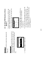
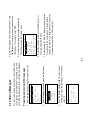
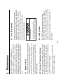
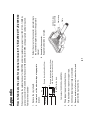
0.12 m
Distance to
100 W/m2 point
0.39 m
Distance to
10 W/m 2 point
Distances at which radiation levels of
2
100 and 10 W/m exist are given in the table.
Handle the handset carefully.
Do not open the equipment.
Do not disassemble or modify the
equipment.
CAUTION
CAUTION
For the operator
SAFETY INSTRUCTIONS
Water in the equipment can result in fire,
electrical shock or equipment damage.
Do not install the equipment where it
may get wet from rain or water splash.
Fire or electrical shock can result if the
power is left on.
Turn off the power at the switchboard
before beginning the installation.
Only qualified personnel
should work inside the
equipment.
Do not open the equipment
unless totally familiar with
electrical circuits and
service manual.
ELECTRICAL SHOCK HAZARD
WARNING
v
WARNING
Loundspeaker
Handset and
bracket
Transceiver
unit
1.40 m
1.50 m
2.20 m
0.65 m
Steering
compass
2.05 m
0.95 m
Standard
compass
Observe the following compass safe
distances to prevent interference to a
magnetic compass:
Ground the equipment to
prevent electrical shock and
mutual interference.
CAUTION
Connection of an incorrect power supply
can cause fire or equipment damage. The
voltage rating of the equipment appears
on the label above the power connector.
Be sure that the power supply is
compatible with the voltage rating of
the equipment.
For the installer
3.4 Selecting USA, INT, WX Channel...................... 15
3.3 Adjusting the Dimmer, Contrast......................... 14
3.2 Listening for Telephony Calls ............................ 14
3.1 Turning the Power On/Off ................................. 14
3. VHF Telephone Operation ......................... 14
2.1 Controls, Indications, LEDs............................... 10
2. Controls...................................................... 10
1.3 Handset Connection............................................ 9
1.2 Transceiver Connections..................................... 5
1.1 Mounting ............................................................. 1
1. Installation.................................................... 1
Introduction..................................................... xi
Equipment Lists.............................................. ix
System Configuration .................................. viii
SAFETY INSTRUCTIONS................................ iv
Receiving Distress Alert from Other Ship...... ii
DISTRESS Call Procedure................................ i
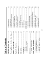
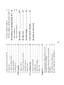
Table of Contents
vi
4.8 Receiving DSC Calls ......................................... 27
4.7 Sending an All Ships Call ................................ 26
4.6 Sending a Group DSC Call................................ 25
4.5 Sending PSTN Call to a Shore Station .............. 23
4.4 Sending DSC Call to a Coast Station ................ 22
4.3 Sending DSC Call to a Ship .............................. 21
4.2 Distress Call by [Call] Key ................................. 20
4.1 Distress Call ...................................................... 19
4. DSC Operation............................................19
3.15 Keyboard Lock................................................. 18
3.14 Intercom .......................................................... 18
3.13 Starting/Stopping Scanning ............................. 17
3.12 Dual Watch ...................................................... 17
3.11 Making a Telephone Call ................................. 17
3.10 Receiving a Telephone Call ............................. 16
3.9 Setting Transmitter Power ................................. 16
3.8 Muting the Loudspeaker .................................... 16
3.7 Adjusting Loudspeaker Volume ......................... 16
3.6 Adjusting Squelch.............................................. 15
3.5 Selecting Channel ............................................. 15
PRIVATE CHANNELS (U.K. MARINERS)............... 47
VHF Weather Channel Frequencies ....................... 46
VHF Channel Frequencies (Marine and Inland
waterways) .............................................................. 42
How to fabricate the cable for optional connector
17JE-23250-02/17JE-23090-02 .............................. 41
Appendix ........................................................ 41
6.4 Menu Tree ......................................................... 40
6.3 Self check Messages ........................................ 39
6.2 Diagnostics........................................................ 38
6.1 Easy Troubleshooting........................................ 36
6. Troubleshooting......................................... 36
5.4 Battery Check.................................................... 35
5.3 Fuse Replacement ............................................ 35
5.2 Cleaning of Transceiver, Handset ..................... 35
5.1 Antenna Check.................................................. 35
5. Maintenance............................................... 35
4.13 Message Log................................................... 33
4.12 Storing Messages............................................ 31
vii
Declaration of Conformity
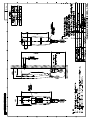
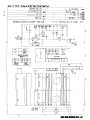
Interconnection Diagram ............................. S-1
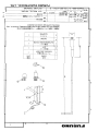
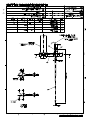
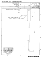
Outline Drawings..........................................D-1
Packing Lists ................................................A-1
Specifications .............................................SP-1
Communication Distance......................................... 49
Rules and Manners ................................................. 48
General Notes on Operating Marine VHF..... 48
PRIVATE CHANNELS (NETHERLANDS-INLAND). 47
4.10 Storing IDs....................................................... 29
4.11 Storing Telephone Numbers ............................ 30
PRIVATE CHANNELS (NORDIC)............................ 47
4.9 Manual Entry of Position and Time.................... 28
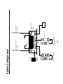
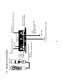
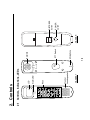
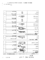
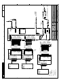
REMOTE HANDSET A
POWER
DISTRESS
viii
(OPTION)
CH70
RX ANT
(RB-2721B or C)
NAV device
(IEC61162-1)
GGA,RMC,GLL,ZDA
TRANSCEIVER
UNIT
FM-2721
(OPTION)
CH70 RX ANT
IEC61162-1(NMEA)
REMOTE HANDSET B/C
(HS-2721)
-
12VDC
+
12V DC
REMOTE 2
MAX 50m
(OPTION)
GROUND
REMOTE 1
(OPTION)
VHF & CH70 RX ANT
5m
or
10 m (option)
SPKR
ANT
(RB-2721A)
(OPTION)
(HS-2721)
(SEM-21Q)
SPEAKER
System Configuration
(150M-W2VN)
(5D-2V)
(150M-W2VN)
(5D-2V)
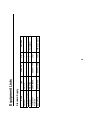
HS-2721
FM-2721
RB-2721A
CP05-08000
SP05-01600
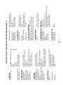
Transceiver Unit
Bracket
Installation
Materials
Spare Parts
Type
Handset
Name
Standard Supply
Equipment Lists
004-542-060
000-057-744
-
-
-
Code No.
ix
1 set
1 set
1
1
1
Qty
10A Fuse: 2 pcs
For handset
Remarks
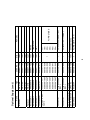
AP05-00810
AP05-00820
AP05-00900
SEM-21Q
05S0308 *5 M*
05S0308 *10 M*
05S0308 *20 M*
05S0308 *30 M*
05S0308 *40 M*
05S0308 *50 M*
17JE-23250-02
(D8C)
17JE-23090-02
(D8C)
PC-208A
OP05-92
05S9364
Antenna Kit
Antenna Kit
Antenna Kit
Loudspeaker
Twisted 10 pair
Cable
Connector
Connector
DC-DC Converter
CH-70 Antenna Kit
Cable Assy
000-057-770
RB-2721C
000-150-844
005-376-120
000-142-469
000-132-624
000-120-946
000-107-578
000-106-038
000-106-039
000-106-040
000-106-041
000-106-042
000-144-917
000-057-739
000-057-723
000-057-722
000-057-736
000-057-737
RB-2721A
HS-2721
000-057-738
Code No.
RB-2721B
Type
Handset
Bracket
Name
Optional Supply (cont.)
x
1
1 set
1
1
1
1
1
1 set
1 set
1 set
1 set
1 set
1 set
1 set
Qty
For RB-2721B/C
For RB-2721A, 10 m
Connector assy.
For IEC61162-1 (NMEA)
For 05S0308 (REMOTE2)
5m
10 m
20 m
30 m
40 m
50 m
396-1
150M-W2VN
RA106
Remarks
Thank you for considering and purchasing FURUNO.
xi
Please carefully read this manual and follow the recommended procedure for installation, operation and maintenance.
With proper care, your equipment should provide years of enjoyable and dependable communications.
Your equipment is designed and constructed to provide commercial grade performance and reliability, yet is
affordable for pleasure craft owners.
For more than 50 years FURUNO Electric Company has enjoyed an enviable reputation for quality and reliability
throughout the world. This dedication is furthered by our extensive global network of agents and dealers.
Congratulations on your choice of the FURUNO FM-2721 Marine VHF Radiotelephone. We are confident that you will
enjoy many years of trouble-free operation with this fine piece of equipment.
A Word to the Owner of the FM-2721
Introduction
25 W radiotelephone with control in palm
Intercom facility
Compact transceiver unit allows installation where
space is limited
• ATIS (Automatic Transmitter Identification System)
mode enables use of the radiotelephone on inland
waterways, also use with the class D DSC (ID
registrations required).
• “Dual watch” monitors CH16 while watching on
another channel.
• Extensive message storage
•
•
•
Features
xii
•
•
•
•
•
•
•
•
Conforms to the following regulations
European Standard EN 301 025 (VHF with Class D
DSC)
European Standard EN 300 698 (VHF used on
inland waterways)
ITU Radio Regulations Appendix 18: Table of
transmitting frequencies 156 – 174 MHz for stations
in the mobile service
ITU-T Recommendation E.161:
Arrangements of digits, letters and symbols on
telephones and other devices that can be used for
gaining access to a telephone network
IEC61162-1: Maritime navigation and
radiocommunication equipment and Systems –
Digital Interface Part 1: Single and multiple listeners
MSC/Circ.803: Participation of non-SOLAS ships in
the Global Maritime Distress and Safety System
ITU-R Recommendation M.493-9: Digital
selective-calling system for use in maritime mobile
service
It is recommended to install the equipment in the
cabin so as to avoid spray.
The equipment should be located as near to the
power source as possible, and as far apart as
possible from any devices that may cause
interference such as direction finders, navigation
receivers and other onboard electronics.
Compass safe distances (Standard compass,
Steering compass) are;
•
•
•
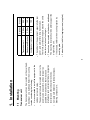
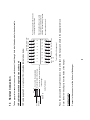
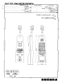
The transceiver unit can be mounted on the overhead,
a desktop or on a bulkhead. Select the mounting
location considering the following:
Transceiver unit
1.1 Mounting
1. Installation
1
The unit can be mounted on the deck or a bulkhead.
The mounting location should be able to support the
weight of the unit.
If necessary, reinforce the mounting location by
doubling plate.
Fasten the unit with four tapping screws (supplied).
•
•
•
1.50 m
The cabinet of the equipment, especially the rear
panel, gets warm after a long transmission.
Therefore, provide some space around the unit to
allow for circulation of cooling air.
2.20 m
Loudspeaker (option)
1.40 m
0.65 m
Steering
•
2.05 m
0.95 m
Handset and Bracket
Transceiver unit
Standard
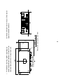
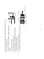
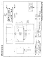
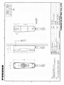
240
4- 5 Fixing Hole
2
200
bulkhead, and screw slots of the unit. Then fasten
upper screws and washers.
Transceiver unit, top and side view
For bulkhead mounting, tighten upper tapping
screws (supplied) and washers so there is 5 mm
clearance between bottom of screw head and
14
74
•
140
57
12 Cable entrance hole
2-
4.5 Fixing hole
3
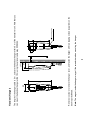
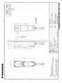
Note: The magnet inside the hanger may pull the screwdriver when mounting the hanger.
Remove six screws to remove the hanger cover, and fasten the hanger with two tapping screws (supplied) on the
desktop or bulkhead.
65
208
(77)
22
The length of the hanger cable is 5 m, so locate the handset hanger within 5 m of the transceiver unit. Note that you
can mount the handset hanger within 10 m using the optional cable assy 05S9364.
Handset (Hanger)
42
145+0.5
4
Lay the antenna, and then solder the M-type connector onto the cable end as shown on page 7.
Any 50 ohm coaxial cable heavier than 5D-2V or RG58C/U may be used for the connection between the antenna and
the transceiver unit. Make sure to leave some slack in the cable loop behind the transceiver for service and
maintenance ease.
Frequency range: 155 MHz to 164 MHz
Impedance:
50 ohms
Polarization:
Vertical
Input power:
25 W
Quality:
Able to withstand marine environment
However, any good quality antenna, complying with the following requirements, may be arranged locally. A high-gain
antenna is preferable. If you are not sure, consult with your dealer.
Provide a location as high and clear as possible, free from the influence of nearby antenna, rigging and masts.
Antenna Connection (option)
HS-2721
RB-2721A
SPKR
ANT
REMOTE 1
Remote 1
Connect the handset bracket.
SPKR
Connect the
optional
loudspeaker.
CH70
RX ANT
IEC61162-1 (NMEA)
Connect the navigator.
Ship's mains
12VDC
Connect the power cable
(05S0388, option).
IEC61162-1(NMEA)
12 VDC
CH70 RX ANT
Connect the optional CH70 RX antenna.
5
Remote 2
Connect the optional handset bracket.
REMOTE 2
Transceiver Unit
FM-2721
Ground
ANT
Connect the optional antenna.
1.2 Transceiver Connections
)
6
Connect the antenna cable (option) here. Use the optional antenna kit (RG-58/C/U cable).
ANT
While special grounding is not generally required for VHF radiotelephones, it is a good practice to properly ground all
electronic equipment to the ship’s ground system. The FM-2721 can be connected to ground by attaching a wire to
the ground screw on the transceiver unit’s rear panel and then to the nearest ship’s ground connection point.
Ground (
Connect the 10P cable (supplied) here.
Remote1, 2
Note:The power cable supplied is 3 meters in length; however it could be shortened as much as possible to prevent
power loss.
Connect the power cable to the connector attached at the rear of the transceiver unit. The RED wire and the BLACK
wires, with inline fuses (10A), connect the transceiver unit to the ship’s 12 VDC power supply.
Power Connection
7
7. Screw the plug into the ANT connector at the rear of the main unit.
6. Screw coupling ring into plug assembly.
5. Solder plug assembly to braided shield through solder holes.
Solder contact sleeve to conductor.
4. Screw the plug assembly on the cable.
3. Slide coupling ring onto cable.
2. Bare 23 mm of the center conductor. Trim braided shield by 5 mm
and tin.
1. Remove the sheath by 30 mm.
Coupling ring
Cut conductor here.
Contact sleeve
Insulator
Conductor
2 mm
30 mm
Solder both
sides of hole.
5 mm
Plug assembly
Braided shield
Sheath
Lay the coaxial cable and attach an M-type plug (if necessary) to the cable as right.
RMC: Generic navigation information
GGA: GPA position, UTC
ZDA: UTC, day, month, and year
•
•
•
•
8
TLL: Target data (Outputs the position data of the ship in distress to the navigation device, for example, plotter,
connected.)
(Output):
GLL: Latitude and longitude
•
(Input):
Connects navigator here. The FM-2721 can input/output the following sentences in NMEA/IEC61162-1 format. Use
the 17JE-23090 connector (option) and interconnection cable type EV-SA7/0.16TAx2P (local supply).
IEC61162-1 (NMEA)
Connect the optional loudspeaker here.
SPKR
Connect the optional CH70 RX antenna kit. For detail, ask your dealer.
CH70 RX ANT
Connect to the terminal block #16
in the hanger.
Connect to the appropriate
terminal block in the hanger.
Cable Fablication
6
10
2
4
11 12
3
13
5
7
14 15
6
16
8
Terminal Block Arrangement
WHT BLK GRN BLU PPL WHT BLK Drain
(B)
(B)
9
1
Not used cables: Cutt off.
Drain wire should be covered by
vinyl sheath, or soldered to the
shield in the cable to be grounded.
Push the appropriate switch down
to insert/pull out the cable.
Connect to the connector at the bottom of the hanger.
Handset cable
9
Cover the hole with soft putty from the inside of the hanger.
Pass the above cable through the entrance hole at the back of the hanger, and attach to the appropriate block.
Drain wire
Anticorrosive
Sheath
80
GRN/ BLU/ ORG/ YEL/
BRW RED ORG YEL WHT WHT WHT BLK
10P cable (supplied 5 m or optional 10 m) should be fabricated as below.
10P cable between the hanger and transceiver unit
Take appropriate measures to ensure water does not leak through hole in bulkhead made for handset cable.
1.3 Handset Connection
Alarm
HANDSET
Monitor
Loundspeaker
Keys
Alarm LED
LCD
2.1 Controls, Indications, LEDs
2. Controls
PTT
10
Microphone
PTT Switch
Earpiece
HANGER
POWER
switch
DISTRESS
button
[ ] key: (Long press) Turns the loudspeaker on/off
[SQ.auto ] key: (Long press)Turns automatic
squelch on/off; (Short press) shifts cursor right word on
alphanumeric selection screen.
[ ] key: Adjusts selected item in downward direction,
volume and squelch down.
[SQ ] key: Adjusts squelch. Shifts cursor left ward on
alphanumeric selection on screen.
[Enter] key: Terminates keyboard input.
[ ] key: Adjusts selected item in upward direction,
volume and squelch up.
[File] key: Sends stored DSC call file.
[Cancel] key: Cancels last operation and returns to
previous display.
[Log] key: Displays received DSC call log.
[Call] key: Sends DSC call.
Alarm LED: Lights when a DSC call is received.
(The alarm sounds also when a DSC call is received.)
DISTRESS button (in hanger): Sends the distress
alert when pressed more than three seconds.
POWER switch (in hanger): Turns the system on/off.
Control, LED description
11
Microphone: Speak in to the microphone while
pressing the PTT switch.
PTT switch: Press to talk; release to listen.
Earpiece: Receiver for the handset.
Monitor loudspeaker: Monitors receive signal when
handset is on hook.
[CH16] key: Immediately selects CH16.
[Private] key: Selects private channel. (System setting
is required.)
[CH /INT/USA] key: Selects international, USA or WX
(wheather) channel alternately. (System setting is
required.)
[Setup] key: Opens the Setup menu.
[IntC] key: Enables intercom between #1 and #2
handsets. Press this key over one second.
[Lock] key: Locks/unlocks keyboard. Press this key
over one second.
[ ] key: Adjusts LCD contrast and panel backlighting.
Press this key over one second.
[H/L key]: Alternately selects transmitter output power
of 1 W or 25 W. Press this key over one second.
[Scan] key: Starts/stops scanning. Press this key over
one second.
Tx (Transmit) or
Rx (Receive)
DSC Display
("DISTRESS MODE" appears
after the distress call is transmitted.)
SQ:03
CH70
Squelch Setting,
00-10 or At (auto)
CH no.
Transmitter Power
(1W or 25W)
12
*: Only when ATIS ID is entered at the initial setting.
Loudspeaker volume
setting (MUTE appears
when loudspeaker is off.)
25W
16
SIMP
Channel Display
(Simplex or Duplex)
VOL:08
WatchVHF
Rx
SCAN
INTL
Channel Mode
(INTL, USA, WX,
ATIS* or PRIV)
Scan (scanning) or
DW (Dual Watch)
Disappeared normally.
Off hook state
Indications
DSC Display
("DISTRESS MODE" appears
after the distress call is transmitted.)
Squelch Setting,
00-10 or At (auto)
Transmitter Power
(1W or 25W)
13
*: Only when ATIS ID is entered at the initial setting.
Loudspeaker volume
setting (MUTE appears
when loudspeaker is off.)
Lat/lon, and UTC
(only when GPS is
connected. If not,
hyphen appeares.)
Channel Display
(SIMP or DUP)
INTL
SIMP
25W
Rx
16
Lat: 45.23 N
Lon:121.88 E
Time:10:57UTC
VOL:08
SQ:03
WatchVHF
CH70
Channel Mode
(INTL, USA, WX,
ATIS* or PRIV)
Rx (receive) and CH no.
On hook state
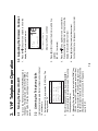
3. (Manually) Set the squelch level with the [SQ ] key
(“SQ:XX” on the LCD is displayed in reverse video)
and then press [ ] or [ ] key. Adjust the squelch so
that noise is just silenced. (Automatically) Press the
[SQ.auto ] key over one second. "At” appears
next to “SQ”.
2. Adjust loudspeaker volume by pressing [ ] [ ]
(three sub-levels in a main level, see 3.7 Adjusting
Loudspeaker Volume).
INTL
SIMP
25W
Rx
16
Lat: 45.23 N
Lon:121.88 E
Time:10:57UTC
VOL:08
SQ:03
WatchVHF
CH70
1. Select channel 16 by press the [CH16] key. The
display shows “16”.
International rules require that all ships monitor channel
16 continuously.
3.2 Listening for Telephony Calls
14
16
25W
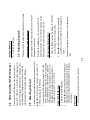
4. Press [ ] or [ ] key to adjust the contrast.
Contrast indication will disappear five seconds later.
3. Press the [ ] key again over one second within
five seconds after the dimmer setting to show the
display for adjustment of contrast.
2. Press [ ] or [ ] to adjust the dimmer within five
seconds.
(00 – 03, four levels).
Display in off hook condition
VO L c h a n g e s t o D i m m e r
Dimmer:03
WatchVHF
CH70
Rx
SCAN
SIMP
1. Press the [ ] key over one second to show the
display for adjustment of dimmer.
To turn on the FM-2721 press the [POWER] switch in
the hanger. The illumination LED in the [POWER]
switch lights. Press the switch again to turn off the
power.
INTL
3.3 Adjusting the Dimmer, Contrast
3.1 Turning the Power On/Off
3. VHF Telephone Operation
2. Press the numeric key to enter the channel.
Direct input
3. Operate [ ] or [ ] until desired channel appears, or
enter channel number with numeric keys. (Private
channels must be selected beforehand. Please ask
your dealer.)
2. Press the [CH/INT/USA] key.
Using [CH], [ ] [ ] keys
1. Press the [CH /INT/USA] key to show INTL, USA,
WX or ATIS (depending on the initial setting) at the
top of the display. For private channel, press the
[Private] key over three seconds to show CH 1 to
255 (when ATIS is selected channel number is
prefixed with”R”), CH F, CH L, or CH P.
Channels can be entered three ways: pressing the [CH]
[ ] [ ] keys, direct numeric key input, and in case of
CH16 by pressing the [CH16] key.
3.5 Selecting Channel
Press the [CH /INT/USA] key over three seconds to
show INTL, USA, WX or ATIS (for inland waterways) at
the top of the display. Mode sequence is depending on
the initial setting. Please ask your dealer. (Only the
international mode is available at the shipment.)
3.4 Selecting USA, INT, WX Channel
15
The squelch setting is shown next to the indication
“SQ.”
2. Press [ ] or [ ] to adjust squelch. (If automatic
squelch is in use the indication “At” changes to a
figure.)
1. Press the [SQ ] to show the display “SQ:XX (XX=
current setting rate)” in reverse video.
Manual squelch adjustment
Press the [SQ.auto ] key over one second to turn
automatic squelch on or off. “SQ:At” appears on the
display when the automatic squelch is active.
Optimal squelch level is automatically set to mute the
background noise level.
Automatic squelch adjustment
The squelch can be adjusted automatically or manually.
3.6 Adjusting Squelch
2. Press the [CH16] key.
Setting channel 16
1. You can control the transmitter power level at the
handset, which can be set to either 1 W or 25 W.
Low and high power are shown on the display as
1W and 25W. Note that some channels are
programmed to operate at 1W only. See the list at
3.9 Setting Transmitter Power
2. To mute the loudspeaker, press the [ ] key over one
second to show “OFF” next to indication “VOL”.
Repeat the procedure to activate the loudspeaker.
1. The handset automatically mutes the loudspeaker
when the PTT switch is pressed, provided the
speaker is active, and then reactivates the
loudspeaker when the PTT switch is released.
3.8 Muting the Loudspeaker
Note: Only Remote 1 is available.
The loudspeaker can be adjusted by pressing [ ] or [ ]
adjust volume. The setting range is 00-10, with three
sub-levels between each main levels. Each pressing of
[ ] or [ ] key changes the volume, however the volume
indication changes only when reaching a next whole
number. For example, if the current volume setting is
main level 01, you would need to press the [up] key
three times to reach main level 02.
3.7 Adjusting Loudspeaker
Volume
16
6. Press the PTT switch to talk: release it to listen. If
you are using a simplex channel (Tx and Rx
frequencies are the same) say “over” every time
you have finished talking
5. Switch to channel agreed upon and communicate.
For close-range communication use 1 W transmitter
power.
4. Release the PTT switch.
2. Press the PTT switch on the handset.
3. To answer the call say
a) The name of the calling station
b) Your station name
c) Suggested channel number
d) Over.
Example: Voyager, This is FURUNO, Channel 06,
Over
1. Hook off the handset.
When a call arrives your call name is heard in the
loudspeaker.
3.10 Receiving a Telephone Call
2. To change the transmitter power, press the [H/L] key
over one second to show 1W or 25W on the display.
the back of this manual.
Note: For ATIS mode, the ATIS ID signal is transmitted
when the PTT switch is released. While the ATIS
ID signal is being transmitted, you cannot
communicate (by pressing the PTT switch).
Communicate after “Rx” appears on the display.
6. Press the PTT switch to talk: release it to listen. Say
“over” every time you have finished talking.
5. When answered, confirm channel to use and switch
to that channel.
4. Release the PTT switch to listen.
Example: Voyager, Voyager, Voyager. This is
FURUNO, FURUNO, FURUNO, Over.
17
1. Select a channel.
3. Press the PTT switch and say
a) Called station name 3 times
b) This is [your station name] 3 times
c) Over
Press the [Scan] key over one second to start the
scanning.
Scanning can be stopped with the any key without
[Lock] key.
3.13 Starting/Stopping Scanning
(except ATIS mode)
To escape from the Dual Watch mode, press any key
except [Enter], [ ] and [ ].
“DW”, “16” and the working channel selected appear on
the display and scanning begins. If a signal is present
on CH16 the receiver locks on CH16 and ignores other
channels. After the signal has gone, the receiver stays
on CH16 until the signal goes away, and then reverts to
the Dual Watch mode.
2. Press the [DW] key over one second.
The dual watch mode allows you to monitor CH16 and
another channel. To activate the Dual Watch set the
squelch and then do the following:
1. Select channel 16 or another channel specified or
agreed upon.
2. Hook off the handset.
3.12 Dual Watch (except ATIS mode)
3.11 Making a Telephone Call
To turn off the intercom, hook on the handset.
If no one answers, press the [Cancel] key to quite
the intercom function.
3.
Note: Intercom cannot be used at Remote 2 when
Remote 1 is off hook, however the reverse condition is
possible. (Remote 2 becomes available when Remote
1 is on hooked.)
Hook off the handset (if it is not already off), and
talk into the microphone to call other handset.
INTERCOM On
SQ:03
16
Display in on hook
INTL SIMP
25W
Rx 16
Lat: 45.23 N
Lon:121.88 E
Time:10:57UTC
VOL:08
SQ:03
Intercom
2.
VOL:08
Intercom
Rx
Display in off hook
INTL SIMP
25W
Press the [IntC] key over one second to turn the
intercom on. The indication Intercom appears at the
bottom of the display when the intercom facility is
on.
18
To lock or unlock the keyboard press the [Lock] key
over one second.
Some keys can be locked to avoid accidental channel
changes during telephone operation. When the
keyboard is locked the only functions which can be
operated are [CH16] and [DISTRESS] keys.
The intercom facility enables communication between
two handsets on board your ship.
1.
3.15 Keyboard Lock
3.14 Intercom
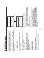
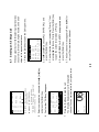
Continue pressing the button until the display looks
something like the sequence in right column.
e) High power (25 W) is selected.
d) CH70 is selected.
c) Speaker is turned on.
b) Distress LED flashes.
3. Open the DISTRESS button lid and press the
[DISTRESS] button over four seconds. The
equipment sets up as follows:
a) Alert sounds.
2. Hook off the handset.
1. Press the [POWER] switch in the hanger to turn on
the unit if it is not already on.
Do the following when a life endangering situation
arises on your vessel:
4.1 Distress Call
This chapter shows you how to set up and send DSC
calls. For each type of call the display shows the
message “XXX call in progress” (XXX = name of call)
while the call is being sent. If, when preparing a DSC
call, no data is entered for five seconds, the equipment
reverts to standby.
4. DSC Operation
19
4. After the distress call is transmitted the alert sound
stops, CH70 and high power are selected. The
display then shows the message “Waiting for
acknowledge,” meaning your station is awaiting
acknowledgement of your distress call from a coast
station. The time to wait is randomly set, from 3.5 to
4.5 minutes.
f) The display shows type of call (distress), nature of
distress, your position in latitude and longitude and
time.
g) All keys are not operative.
The equipment then sets up as follows:
(Example of transmitting display)
Distress call
in progress
Nature:
UNDESIGNATED
Position:12:34
12.34.E123.45N
After 3 seconds
Distress
button
pressed!!
Nature:
UNDESIGNATED
KEEP PRESSED
FOR
3SEC.
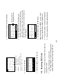
5. When you receive a distress acknowledge call from
a coast station the alarm beeps.
6. Hook off the handset if it is not already off hook.
Press the PTT switch and say:
a) MAYDAY three times.
b) This is [9-digit identity (MMSI number) and call sign
or vessel name] - three times.
c) MAYDAY
d) This is [9-digit identity (MMSI number) and call sign
or vessel name].
e) Position
f) Nature of DISTRESS
g) Kind of assistance needed
h) Number of crew
i) Other info such as description of your vessel
j) Over.
Wait for ack.
Auto re-Xmit
DISTRESS CALL
Nature:
UNDESIGNATED
Pos.
:12:34
12˚34E123˚45N
Do nothing until you receive the distress
acknowledge call. If the call is not acknowledged,
this sequence is repeated. The distress call can be
canceled by using the [Cancel] key.
20
Natur of dist.
LISTING
SINKING
DISABLE
ABANDONING
PIRACY
MAN OVERBOARD
Operate [ ] or [ ] to select
nature of distress.
Natur of dist.
UNDESIGNATED
FIRE
FLOODING
COLLISION
GROUNDING
LISTING
3. Confirm that “Nature” is selected, and then press
the [Enter] key to open the Nature of dist. menu.
2. Press [ ] to select DISTRESS CALL and press the
[Enter] key to open the Send message menu.
Call type
COAST CALL
SHIP CALL
PSTN CALL
GROUP CALL
ALL SHIPS CALL
DISTRESS CALL
1. Press the [Call] key to show the Call type menu.
This method of sending the distress call allows you to
specify nature of distress.
4.2 Distress Call by [Call] Key
3. Enter the Ship ID and press the [Enter] key. Ship ID
(9 digits) may be entered manually with the numeric
keys or automatically through the Addr. Sel. file.
(Registration of ID required for automatic input. See
“4.10 Storing IDs” on page 29.)
2. Use [ ] or [ ] to choose SHIP CALL and press the
[Enter] key to open the Send message menu..
Call type
COAST CALL
SHIP CALL
PSTN CALL
GROUP CALL
ALL SHIPS CALL
DISTRESS CALL
1. Press the [Call] key to display the Call type menu.
To send a DSC call to a ship to propose a working
channel, do the following:
4.3 Sending DSC Call to a Ship
6. Follow from step 4 in “Distress Call by DISTRESS
Button” on page 19.
5. Press the [Enter] key to send the distress call.
4. Scroll the display with [ ] or [ ] to select appropriate
nature of distress among Undesignated, Fire,
Flooding, Collision,
Grounding, Listing, Sinking, Abandoning, Piracy,
and Man Overboard.
21
06
NO.3
03:FRIEND
Automatic entry through Addr. sel. file
NO.2
02:FRIEND
Addr. sel.
01:FURUNOMARU
Automatic input
Press the [File] key. Scroll the display with [ ] or [ ] to
select the recorded name which you desire and press
the [Enter] key.
Manual entry
Com channel:
Send message
Call type:
SHIP CALL
Ship ID:
Manual input
Key in Ship ID with the numeric keys and press the
[Enter] key.
Com
73
69
67
77
15
17
CH Busy
MANUAL
channel
No INFO
8. Press the [Call] key to send the call.
After transmitting a ship’s call, FM-2721 goes to the
waiting condition, and then the following message may
occur.
Rcvd message able ack: You can communicate.
Rcvd message unable ack: Receiving station cannot
communicate now. Other suggestion may be sent.
No response: Your call is deleted.
12: Mess. Entry
Call type:
SHIPS CALL
SHIP ID:
123456789
Com channel:
06
7. Press the [Enter] key.
6. Confirm that “CH Busy” disappears.
5. Select the communication channel with [ ] [ ] key.
NO INFO: Receiving station
sets channel.
MANUAL: Enter channel
w i t h n u m e r i c k e y.
"CH BUSY" means the selected
c h a n n e l i s bu s y n o w.
06
08
10
13
09
72
4. Press the [Enter] key to open the Com channel
menu.
22
Automatic entry from Addr. sel. file
03:
02:KOBE COAST
Addr. Sel.
01:TOKYO COAST
Manual entry
Send message
Call type:
COAST CALL
Coast ID:
00
2. Confirm that the cursor is selecting COAST CALL.
3. Press the [Enter] key to open the Send message
menu.
4. Enter the Coast ID and press the [Enter] key. Coast
ID (7 digits) may be entered manually with the
numeric keys or automatically through the Addr. sel.
File. (Registration of ID required for automatic input.
See “4.10 Storing IDs”.)
Call type
COAST CALL
SHIP CALL
PSTN CALL
GROUP CALL
ALL SHIPS CALL
DISTRESS CALL
To send a DSC call to a coast station, do the following:
1. Press the [Call] key to open the Call type menu.
4.4 Sending DSC Call to a Coast
Station
5. Press the [Call] key to send the call.
Send message
Call type:
COAST CALL
Coast ID:
001234567
Automatic input
Press the [File] key to show the “Addr. Sel.” file. Scroll
the display with [ ] or [ ] to select the registered coast
station name which you desire and press the [Enter]
key.
Manual input
Key in Coast ID with the numeric keys and press the
[Enter] key.
23
3. Enter the Coast ID and press the [Enter] key. Coast
ID (7 digits) may be entered manually with the
numeric keys or automatically through the Addr. Sel.
file. (Registration of ID required for automatic input.
See “4.10 Storing IDs”.)
2. Scroll the display with [ ] to choose PSTN CALL
and press the [Enter] key to open the Send
message menu.
Call type
COAST CALL
SHIP CALL
PSTN CALL
GROUP CALL
ALL SHIPS CALL
DISTRESS CALL
1. Press the [Call] key to open the Call type menu.
To connect to a office or home via a PSTN (Public
Switched Telephone Network), do the following:
4.5 Sending PSTN Call to a Shore
Station
4. Confirm that Tel No: is selected..
5. Enter the Telephone No. and press the [Enter] key.
Telephone number may be entered manually with
the numeric keys or automatically through the Tel.
No. sel. file. (Registration of telephone number
required for automatic input. See “4.11 Storing
Telephone Numbers.)
Automatic input
Press the [File] key. Scroll the display with [ ] or [ ] to
select the registered coast name which you desire and
press the [Enter] key.
Manual input
Key in Coast ID with the numeric keys and press the
[Enter] key.
Automatic entry from Addr. sel. file
03:
COAST
24
6. Press the [Call] key to send the call.
“PSTN in progress” “Waiting for acknowledgement”
appears on the screen, and then you can make
telephone call via coast station.
Send message
Call type:
PSTN CALL
Coast ID:
001234567
TelNo.:123456
7890123456789
Manual input
Key in telephone number with the numeric keys and
press the [Enter] key.
Automatic input
Press the [File] key. Use [ ] or [ ] to select registered
name which you desire and press the [Enter] key.
Automatic entry through Tel. No. sel. file
03:Dealer
Tel. No. sel.
01:FURUNO
OFFICE
02:HOME
Addr. sel.
01:TOKYO COAST
02:KOBE
Manual entry
Send message
Call type:
PSTN CALL
Coast ID:
00
Tel No.:
Manual entry
Send message
Call type:
PSTN CALL
Coast ID:
00
3. Enter the Group ID (8 digits) and press the [Enter]
key. Group ID can be entered manually through the
keyboard or automatically by using the Addr. Sel.
file. (Registration of ID required for automatic input.
See “4.10 Storing IDs.)
2. Scroll the display with [ ] and [ ] to choose GROUP
CALL and press the [Enter] key.
Call type
COAST CALL
SHIP CALL
PSTN CALL
GROUP CALL
ALL SHIPS CALL
DISTRESS CALL
1. Press the [Call] key to open the Call type menu.
To send a group DSC call, do the following:
4.6 Sending a Group DSC Call
25
4. Press the [ ] key to open the screen for entry of
Communications channel and press the [Enter] key.
Automatic input
Press the [File] key. Scroll the display with [ ] or [ ] to
select group call adress which you desire and press the
[Enter] key.
Manual input
Key in Group ID with the numeric keys and press the
[Enter] key.
Automatic entry through Addr. sel. file
03:GROUP3
02:GROUP2
Addr. sel.
01:GROUP1
Send message
Call type:
GROUP CALL
Groupe ID:
00
Com channel:
06
Manual entry
Com channel
73 No INFO
69
67 MANUAL
77
15 CH Busy
17
VOL:03
Rx
INTL
25W
SQ:At
06
SIMP
7. Press the [Call] key to send the call.
The following display appears with designated
channel. You can communicate with your group ships.
Send message
Call type:
GROUP CALL
Ship ID:
02345678
Com channel:
06
6. Confirm that “CH Busy” disappear.
5. Select communication channel with the [ ] or [ ] key,
and press the [Enter] key.
NO INFO: Receiving station
sets channel.
MANUAL: Enter channel
w i t h n u m e r i c k e y.
"CH BUSY" means the selected
c h a n n e l i s bu s y n o w.
06
08
10
13
09
72
26
Sending an All Ships Call
5. The Com channel menu appears. Press the [ ] for
entry of Communications channel.
4. Select URGENCY or SAFETY as appropriate and
press the [Enter] key.
3. Confirm that the cursor is selecting “Priority”. If not,
press [ ] [ ] to choose Priority. Press the [Enter] key
to open the screen for selection of Priority.
2. Use [ ] and [ ] to choose ALL SHIPS CALL and
press the [Enter] key.
Call type
COAST CALL
SHIP CALL
PSTN CALL
GROUP CALL
ALL SHIPS CALL
DISTRESS CALL
1. Press the [Call] key to open the Call type menu.
When an urgent but not life threatening situation arises
on your ship, for example, engine trouble, send an all
ships call to request assistance.
4.7
Com channel
71 No INFO
74
69 MANUAL
79
80 CH Busy
1. Confirm the message on the screen.
The stand-by display is restored if the handset is not
picked within two minutes of receiving a DSC call.
When your FM-2721 receives the DSC call, follow the
steps shown below.
4.8 Receiving DSC Calls
7. Press the [Call] key to send the call.
Send message
Call type:
ALL SHIPS CALL
Priority:
SAFETY
Com channel:
12
6. Press the [Enter] key.
NO INFO: Receiving station
sets channel.
MANUAL: Enter channel
w i t h n u m e r i c k e y.
"CH BUSY" means the selected
c h a n n e l i s bu s y n o w.
16
12
14
11
13
68
27
Sending station ID
Designated channel
6. Start communications with designated channel.
5. Press the [Call] key to send acknowledgement.
Note: When selecting “UNABLE”, you can select
channel in available and transmit individual call.
4. Select ABLE and press the [Enter] key.
RCVD MESSAGE
SHIP
ROUTINE
MMSI123456789
SIMPLEX TP:12
Err. check:OK
ABLE UNABLE
3. Select ANSWER and press the [Enter] key.
If you don’t want to communicate with other party,
press the [ ] key to select “DEL” and then press the
[Enter] key. However, the party is still waiting for your
acknowledgment.
RCVD. MESSAGE
SHIP
ROUTINE
NMSI123456789
SIMPLEX TP:12
Err. check:OK
ANSWER
DEL
2. Press the [Cancel] key to silence the beep.
Manual Entry of Position and Time
input
4. Press the [ ] key to select MANUAL and [Enter] key.
Pos.
AUTO
MANUAL
3. Press the [Enter] key to display as follows.
(when IEC61162-1 data inputting)
Position
INPUT:AUTO
Lat : 12˚34 N
Lon :123˚45 E
Time:12:34UTC
Now receiving
new data.
2. Select “Position” and press the [Enter] key.
Setup menu
Message entry
Adrr.entry
Tel.NO. entry
Position
Test
System
1. Press the [Setup] key to display the Setup menu.
Position and time data are required when sending a
distress alert call, either automatically by a navigation
device or manually through the keyboard. If there is no
navigation device or the navigation device fails enter
position and time manually as follows:
4.9
28
Position
Input:MANUAL
Lat : 12˚34 N
Lon :123˚45 E
Time:
:
UTC
Unable rcv.
new data.
8. Key in longitude with the numeric keys same as
latitude entering. Use [ ] to switch from East to
West longitude and vice versa. Press the [Enter] key.
The cursor moves to Time.
Position
Input:MANUAL
Lat : 12˚34 N
Lon :
˚
Time:12:34UTC
Unable rcv.
new data.
7. Press the [Enter] key.
The cursor moves to Lon.
6. Key in latitude with the numeric keys. Use [ ] to
switch from North latitude to South latitude and vice
versa.
Position
Input:MANUAL
Lat :
˚
Lon :123˚45 E
Time:12:34UTC
Unable rcv.
new data.
5. Press the [ ] key to clear digits. Each pressing
crears a digit from the right.
3. Scroll the display with [ ] or [ ] to select empty
number and press the [Enter] key. For example,
select 03. The display then looks something like the
one below.
02:FRIEND
SHIP
03:
Addr.entry
01:FURUNOMARU
2. Select Addr. entry and press the [Enter] key.
Setup menu
Message entry
Adrr.entry
Tel.NO. entry
Position
Test
System
1. Press the [Setup] key to display the Setup menu.
You may store often-used coast, group and ship IDs,
and recall them on the screen (with the [File] key) when
preparing a DSC call. (Max. storage: 25 IDs)
4.10 Storing IDs
10. Press the [Enter] key.
9. Enter UTC time with the numeric keys same as
latitude entering and press the [Enter] key. The
display shows position and time.
29
type:
SHIP
*
.
/
'
&
-
:
6. Press the [Enter] key to open the window for
selection of station type.
5. Press the [Enter] key.
To enter FURUNO as the name, for example, do the
following.
a) Press the [3 (DW, DEF)] key four times to enter “F”.
b) Press the [ ] to move the cursor to the next column.
c) Press the [8 (TUV)] key three times to enter “U”.
d) Repeat the above steps to complete the entering
“FURUNO”.
If you make a mistake, press the [ ] to return to the
previous column.
#
1
4. Enter file name (max. 20 characters) with the
alphanumeric keys and press the [Enter] key. For
entry of alphabet or symbol.
Every pressing of [1] key changes the symbol mark.
The symbol mark sequence is as shown below.
Address:
Station
03:Addr.entry
03:
type
type:
COAST
Setup menu
Message entry
Addr.entry
Tel.NO. entry
Position
Test
System
1. Press the [Setup] key to display the Setup menu.
Often-used telephone numbers can be stored, and
display them on the screen (with the [File] key) when
preparing a DSC call. (Max. storage: 25 numbers)
4.11 Storing Telephone Numbers
9. Press the [Cancel] key several time to return.
8. Enter ID number (Group ID, 8 digits; Coast ID, 7
digits, Ship ID, 9 digits) and press the [Enter] key.
Address:
00
Station
03:Addr.entry
03:FURUNO
7. Select station type desired and press the [Enter] key.
For example, select COAST.
COAST
SHIP
GROUP
Station
30
No.:
No.entry
No.:
6. Press the [Cancel] key to escape.
5. Enter telephone number with the numeric keys and
press the [Enter] key. (Max. 16 characters)
For the entering of hyphen, press the [ ].
Tel
Tel. No. entry
03:FURUNO
4. Enter file name (Max. 20 characters) with the
alphanumeric keys and press the [Enter] key.
Tel
Tel.
03:
3. Press the [ ] or [ ] to select vacant number and
press the [Enter] key.
03:
TEl. No. Entry
01:FURUNO
OFFICE
02:HOME
2. Press [ ] to select Tel. NO. entry and press the
[Enter] key.
entry
type:
SHIP CALL
Ship ID:
Call
Mess.
12:
3. Scroll the display with [ ] or [ ] to select vacant
number and press the [Enter] key. For example,
select 12.
Message entry
01:FURUNO
JAPAN
02:FURUNO
SPAIN
03:FURUNO
2. Select Message entry and press the [Enter] key.
Setup menu
Message entry
Addr.entry
Tel.NO. entry
Position
Test
System
1. Press the [Setup] key to display the Setup menu.
Preparing and storing DSC messages
You previously learned how to send various DSC calls.
In this section you will learn how to prepare, store and
send DSC file messages. (Max. storage: 25 messages)
4.12 Storing Messages
31
7. Enter the ship ID. Ship ID (9 digits) may be entered
manually with the numeric keys or automatically
through the Ship ID log. (Registration of ID required
for automatic input. See “4.10 Storing IDs”)
6. Select the call type and press the [Enter] key. For
example, select SHIP CALL.
Call type
COAST CALL
SHIP CALL
PSTN CALL
GROUP CALL
ALL SHIPS CALL
DISTRESS CALL
5. Confirm that call type is selected and press the
[Enter] key to open the call type menu.
4. Enter the message name with alphanumeric keys
([ ] [ ]keys for cursor movement) and press the
[Enter] key. For example, enter “ABC”.
Automatic input
Press the [File] key. Scroll the display with [ ] or [ ] to select the
message name desired and press the [Enter] key.
Manual input
Key in Ship ID with the numeric keys and press the [Enter] key.
Automatic entry through Sel. Ship ID
02:FRIEND
SHIP
03:
Sel. ship ID
01:FURUNOMARU
Manual entry
Mess. entry
12:ABC
Call type:
SHIP CALL
Ship ID:
32
Com channel
73 No INFO
69
67 MANUAL
77
15 CH Busy
17
10. Press the [Cancel] key several times to return.
9. Select channel by pressing [ ] or [ ] key and press
the [Enter] key.
NO INFO: No infor mation
MANUAL: Enter channel
w i t h n u m e r i c k e y.
"CH BUSY" means the selected
c h a n n e l i s bu s y n o w.
06
08
10
13
09
72
8. Confirm that Com channel is selected, and then
press the [Enter] key.
3. Press the [Call] key to send the call.
2. Select file and press the [Enter] key.
1. Press the [File] key to open the file menu.
Selection by cursor
Sending stored messages
33
There are unread or
unacknowledged messages.
2. Select RCVD. ORDINARY, RCVD DISTRESS or
TRANSMITTTED as appropriate and press the
[Enter] key.
RCVD.DISTRESS
Not read log
TRANSMITED
1. Press the [Log] key to open the Sel. Log title menu.
Sel. logtitle
RCVD.ORDINARY
To view the message log do the following:
All ships (Urgency, Safety), Individual (Urgency, Safety,
Routine), Group (Routine)
• RCVD. (Received) DISTRESS: Distress, Distress Ack,
Distress Relay
• TRANSMITTED: All above messages transmitted.
• RCVD. (Received) ORDINARY:
The messages are saved to correspond logs as
follows.
The message log stores 50 each of the latest received
routine messages (other than Distress), received
distress messages, and transmitted messages, each
type in its own memory. When a message log memory
becomes full the oldest message in that memory is
automatically erased to make room for the latest. The
Not read log” has
log file with the message of “
unread or unacknowledged Rx messages,
unacknowledged Tx messages and unread distress
messages.
4.13 Message Log
.
4. Press the [Enter] key to display the message. The
example below shows a received ordinary
message.
keys. Unread messages are marked with
3. Select the message to view by using the [ ] or [ ]
key or entering message number with the numeric
Transmitted log
TRANSMITTED
01.Group call
23-12:40
02.Ship call
23-12:34
03.Ship call
23-12:11
RCVD.DISTRESS
01.Acknowledge
23-12:40
02.Distress
23-12:34
03.Distress
23-12:11
Received distress log
RCVD.ORDINARY
01.Ship Call
23-12:40
02.Coast call
23-12:34
03.Coast call
23-12:11
Received ordinary log
34
8. To escape from the log, press the [Cancel] key
several times.
7. When the
appears at the bottom of the display, it
means that there are more messages. ( is means
the end of message.)
6. To resend (or answer) the message, confirm that
the cursor is selecting RESEND (or ANSWER) and
then press the [Enter] key followed by the [Call] key.
The message of ANSWER changes to RESEND if
there is no operation within 4 minutes and 30
seconds.
5. To delete the message, press the [ ] to select
DEL, and then press the [Enter] key.
RCVD MESSAGE
SHIP CALL
ROUTINE
MMSI123456789
SIMPLEX TP:16
Err. check:OK
RESEND
DEL
Antenna Check
Check all connectors for corrosion. If corroded, clean
the contact and re-tighten securely.
Keep the transceiver and handset clean and dry at all
times. Dust or loose dirt accumulated on them should
be wiped off with a soft, dry cloth. Never use plastic
solvents, such as thinner or acetone for cleaning; they
may dissolve paint and markings.
5.2 Cleaning of Transceiver, Handset
Since the antenna is exposed to direct sunlight and salt
water spray, it is subject to corrosion or salt water
immersion at the antenna base. Physical damage, such
as a crack, may occur under heavy ship’s vibration. If
cracks or water immersion is found, contact FURUNO
dealer for servicing.
5.1
The FM-2721 is designed to provide years of
trouble-free operation. It is, however, recommended to
inspect and maintain the following points to minimize
the possibility of equipment failure and assure optimum
performance. Be sure to disconnect the power cable at
the fuse holders before performing any maintenance
work.
5. Maintenance
35
Fuse Replacement
Battery Check
The FM-2721 operates normally at any voltage
between 10.8 and 15.6 VDC. If the battery voltage is
out of ratings, check the battery liquid and the charging
system of your boat. Check also rust or corrosion at the
battery terminals and the ship’s mains switch-board for
poor contact.
5.4
Use of a wrong fuse can cause fire or
equipment damage and void the warranty.
Use the proper fuse.
CAUTION
A 10A fuse in the snap-in fuse holder on the power
cable protects the equipment from reverse polarity and
equipment fault. If the fuse has blown, first find the
cause of the problem before replacing it. Use only a
10A fuse; use of other fuses will damage the
equipment and void the warranty.
5.3
(Continued on next page)
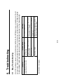
[POWER] switch pressed but
power does not come on.
Symptom
Secure connector firmly and check
connections to battery.
Check battery electrolyte, charging
system, etc.
Check mains voltage and polarity and
then replace the fuse (10A).
Power lead on battery is loose or
disconnected.
Battery is flat.
Fuse has blown.
36
Turns mains switch on.
Remedy
Power is off at the mains
switchboard.
Possible Cause
Most VHF troubles are caused not by the transceiver itself but by the ANT/feeder or power supply system. The list
below provides simple troubleshooting that can be done by the operator. DO NOT ATTEMPT TO CHECK INSIDE
THE EQUIPMENT. CARELESS HANDLING MAY CAUSE PERMANENT DAMAGE TO THE TRANSCEIVER.
6.1 Easy Troubleshooting
6. Troubleshooting
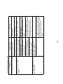
Possible Cause
TX symbol appears but no or
low output power.
Noise but no or poor signal
reception.
Lay new cable (50 ohm coaxial
cable).
Line-of-sight is a rule of VHF
communications. Wait until barrier no
longer exists or you are within
transmitting range of transmitter.
Antenna cable is damaged or
immersed in water.
Radio barrier (large vessel,
crane, etc.) in the signal path.
37
Power setting is “LOW” (1 W)
See items of “Noise but no or
poor signal reception.”
Press the [H/L] key over one second
to display 25 W. Some channels are
programmed to operate at 1 W only.
See the list at the back of this
manual.
Replace antenna.
Antenna has broken.
Transmitter is too far away or
transmitting in low power.
Fasten ANT connector tightly.
Raise loudspeaker.
Lower squelch.
Remedy
ANT connector (on transceiver
unit) is loose or disconnected.
Loudspeaker volume too low.
LCD looks normal but no sound. Squelch setting too high.
Symptom
(Continued from previous page)
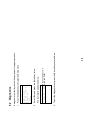
Results displayed as OK
or NG (No Good)
38
3. To quit the diagnostic test, press the [Cancel] key several times.
Daily test
FSK Loop
Check:
OK!
The test results appear as below.
2. Select Test and press the [Enter] key twice.
Setup menu
Message entry
Addr.entry
Tel.NO. entry
Position
Test
System
1. Press the [Setup] key to display the Setup menu.
A diagnostic test facility checks the equipment for proper operation.
6.2 Diagnostics
25W
16
SIMP
25W
16
SIMP
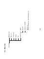
Massage not yet read
VOL:08
SQ:03
Not read log
Rx
SCAN
INTL
PLL unlock
VOL:08
SQ:03
PLL unlock
Rx
SCAN
INTL
25W
16
SIMP
39
Remote Error (Handset Priority)
VOL:08
SQ:03
Remote
Rx
SCAN
INTL
25W
16
SIMP
Press the [Cancel] key,
and "Update pos.!!" replaces
"EPFS Error."
Then, enter position manually.
Position Error
VOL:08
SQ:03
EPFS Error
Rx
SCAN
INTL
The display shows the following messages to alert to possible equipment trouble.
6.3 Self check Messages
[Setup] key
6.4 Menu Tree
System
Test
Position
Tel. No. entry
Addr. entry
Message entry
40
Program ver.
(FM-2721:05502031XX, HS-2721:05502041XX)
Auto revert (ON/OFF)
Key click
MMSI
10
3
6. Remove insulator of all cores for about 4 mm, and
presolder the tip of each wire.
5. Continue wrapping copper tape around cable.
4. Fold back aluminum tape onto copper tape.
3. Wrap copper tape around sheath once.
41
Remove the aluminum tape by 10 mm,
and the sheath of the cores by 3 mm.
Remove the vinyl sheath by 45 mm.
Twist and trim the drain.
Aluminum tape
Fabrication of 05S0308 (for REMOTE2)
Vinyl sheath
45
2. Unravel and cut the aluminum tape at appropriate
location.
1. Remove the vinyl sheath.
8. Assemble the connector.
Supplied rubber tube is not used.
Cable
Cable clamp
Aluminum tape
and copper tape
7. Solder the cores to the connector pins referring to
the schematic diagram at back of the operator’s
manual.
When connecting the optional handset for REMOTE2 and/or navigational equipment to port IEC 61162-1 (NMEA),
optional connector 17JE-23250-02 (for handset)/17JE-23090-02 (for NMEA) and appropriate cable are required.
Fabricate them as below.
How to fabricate the cable for optional connector 17JE-23250-02/17JE-23090-02
Appendix
CH
01
02
03
04
05
06
07
08
09
10
11
12
13
14
Ship Tx
156.050
156.100
156.150
156.200
156.250
156.300
156.350
156.400
156.450
156.500
156.550
156.600
156.650
156.700
Ship Rx
160.650
160.700
160.750
160.800
160.850
156.300
160.950
156.400
156.450
156.500
156.550
156.600
156.650
156.700
(Inland waterways) 1 W
(Inland waterways) 1 W
(Inland waterways) 1 W
(Inland waterways) 1 W
(Inland waterways) 1 W
only
only
only
only
only
(Inland waterways) 1 W only
(Inland waterways) 1 W only
Remarks
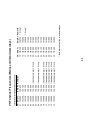
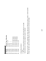
International & Inland waterways Channels:
42
Ship Tx
156.750
156.800
156.850
156.900
156.950
157.000
157.050
157.100
157.150
157.200
157.250
157.300
157.350
157.400
Ship Rx Remarks
156.750 1 W only*
156.800
156.850 1 W only*
161.500
161.550
161.600
161.650
161.700
161.750
161.800
161.850
161.900
161.950
162.000
*: Both International and Inland waterways
CH
15
16
17
18
19
20
21
22
23
24
25
26
27
28
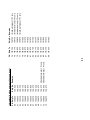
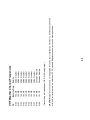
VHF Channel Frequencies (Marine and Inland waterways)
CH
60
61
62
63
64
65
66
67
68
69
71
72
73
Ship Tx
156.025
156.075
156.125
156.175
156.225
156.275
156.325
156.375
156.425
156.475
156.575
156.625
156.675
Ship Rx Remarks
160.625
160.675
160.725
160.775
160.825
160.875
160.925
156.375
156.425
156.475
156.575 (Inland waterways) 1 W only
156.625 (Inland waterways) 1 W only
156.675
International & Inland waterways Channels (cont.):
43
CH
74
75
76
77
78
79
80
81
82
83
84
85
86
87
88
Ship Tx
156.725
156.775
156.825
156.875
156.925
156.975
157.025
157.075
157.125
157.175
157.225
157.275
157.325
157.375
157.425
Ship Rx Remarks
156.725 (Inland waterways) 1 W only
156.775 (International only) 1 W only
156.825 (International only) 1 W only
156.875 (Inland waterways) 1 W only
161.525
161.575
161.625
161.675
161.725
161.775
161.825
161.875
161.925
157.375
157.425
CH
01
05
06
07
08
09
10
11
12
13’
14
15#
16
17*
18
19
20
21”
22
23’
Ship Tx
156.050
156.250
156.300
156.350
156.400
156.450
156.500
156.550
156.600
156.650
156.700
--156.800
156.850
156.900
156.950
157.000
157.050
157.100
157.150
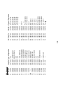
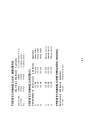
USA Channels:
Ship Rx
156.050
156.250
156.300
156.350
156.400
156.450
156.500
156.550
156.600
156.650
156.700
156.750
156.800
156.850
156.900
156.950
161.600
157.050
157.100
157.150
Type of Operation
Com’l
Port Operations
Intership Safety
Com’l
Com’l
Call & Ship/Ship
Com’l & Ship/Ship
Com’l & Ship/Ship
Port Operations
Nav. Ship/Bridge
Port Operations
Environmental
Emerg/Calling
State Controlled
Com’l
Com’l
Port Operations
--Coast Guard
---
44
CH Ship Tx
24 157.200
25 157.250
26 157.300
27 157.350
28 157.400
61” 156.075
63 156.175
64” 156.225
65 156.275
66 156.325
67** 156.375
68 156.425
69 156.475
71 156.575
72 156.625
73 156.675
74 156.725
77* 156.875
78 156.925
79 156.975
Ship Rx
161.800
161.850
161.900
161.950
162.000
156.075
156.175
156.225
156.275
156.325
156.375
156.425
156.475
156.575
156.625
156.675
156.725
156.875
156.925
156.975
Type of Operation
Public Corresp.
Public Corresp.
Public Corresp.
Public Corresp.
Public Corresp.
--Com’l
--Port Operations
Port Operations
Com’l
Non Com’l
Non Com’l
Non Com’l
Non Com’l
Port Operations
Port Operations
Port Operations
Non Com’l
Com’l:
Ship Tx
157.025
157.075
157.125
157.175
157.225
157.275
157.325
157.375
157.425
Ship Rx
157.025
167.075
157.125
157.175
161.825
161.875
161.925
161.975
157.425
Type of Operation
Com’l
------Public Corresp.
Public Corresp.
Public Corresp.
Public Corresp.
Com’l
45
Note: CH16 is used in all USA coastal areas to call the Coast Guard and for general vessel calling. In certain high traffic
areas, CH09 is also used as the Hailing Frequency. Please check with your local Coast Guard.
# Transmitting is disabled.
* 1 W only
“ 1 watt initially. Can be switched to high power (25 W) while [H/L] key is pressed.
‘ These channels are not for use by the general public in US waters.
CH
80
81”
82”
83”
84
85
86
87
88
USA Channels (cont):
Receive Freq.
163.275
162.550
162.400
162.475
162.425
162.450
162.500
162.525
161.650
161.775
Service
NOAA Weather
NOAA Weather
NOAA Weather
NOAA Weather
NOAA Weather
NOAA Weather
NOAA Weather
NOAA Weather
Canadian Weather
Canadian Weather
46
CAUTION: Operation on channels not designated for use by your classification of craft or on International Channels
within US territorial waters is a violation of FCC Rules and Regulations and may result in severe penalties.
(Transmitting is disabled when WX0 - WX9 is displayed.)
CH
WX0
WX1
WX2
WX3
WX4
WX5
WX6
WX7
WX8
WX9
VHF Weather Channel Frequencies
Ship Receive
156.000
157.850
161.425
155.500
155.525
155.650
L1
L2
L3
155.500
155.525
155.650
Ship Receive
155.625
155.775
155.825
Pleasure craft L1
Pleasure craft L2
Pleasure craft L3
Application
Fishing boat F1
Fishing boat F2
Fishing boat F3
Application
for contact with U.K. C.G.
for pleasure boat
for pleasure boat
Ship Transmit
157.550
Ship Receive Application
162.150
Yacht harbor (CH31)
47
PRIVATE CHANNELS (NETHERLANDS - INLAND)
Ship Transmit
155.625
155.775
155.825
FISHING BOATS CH
F1
F2
F3
PRIVATE CHANNELS (NORDIC)
Coast Guard
M1 (37P)
M2
Ship Transmit
156.000
157.850
161.425
PRIVATE CHANNELS (U.K. MARINERS)
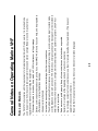
Distress communications have absolute priority. If you hear MAYDAY, talk only if you can help, and be prepared to
offer assistance or relay the distress message.
Use appropriate channels.
Listen before transmitting to avoid interfering with other communications.
The ship Radiotelephone Station Licensee is responsible for recording in a communication log all contacts made
over the telephone and watch period on CH16. All distress, emergency and safety messages must be recorded in
detail. Entries must show boat’s name, call sign, watch start/stop times, and operator’s signature. Use 24-hour
notation to record time.
Radio waves are public property. Keep all communications as brief and clear as possible.
Declare ID or call sign at the beginning and end of each communication.
Do not divulge contents of communications nor use them for private benefit without permission. (This does not
apply to distress communication.)
Be aware that many people are listening. Do not use indecent or profane language.
•
•
•
•
•
•
•
•
48
Whenever the radio is turned on, keep watch on CH16 for distress or calling message.
•
The FM-2721 fully complies with the requirements for international maritime VHF radio service. It is intended to be
used by a person who holds a valid radio operator’s license and station call sign.Below are some important rules,
regulations and manners for operating the equipment.
Rules and Manners
General Notes on Operating Marine VHF
49
Note that an obstruction in the signal path, such as a large ship, crane, building or mountain, can destroy VHF
communications even for a short distance.
The average communication range, using 25 W marine VHF, is 10 to 15 nm for ship-to-ship and 20 to 30 nm for
ship-to-shore.
Even if a clear line-of-sight condition exists, the radio wave is attenuated along the signal path. The communication
distance is limited also by transmitter power, antenna efficiency and receiver sensitivity.
The VHF radio wave, unlike LF or HF, propagates like a light ray. Thus communication is only available with another
VHF antenna which is above the horizon. This is called line-of-sight.
The FM-2721 operates on the VHF band assigned for maritime mobile stations.
Communication Distance
55
57
55
10
20
155.000 to 161.475MHz
25W max., 1W at power reduction
±5 kHz max.
50 ohms
6 dB/oct. +1dB/-3dB, Pre-emphasis
St-by: less than 2 nW
Transmit: less than 0.25 µW
INLAND WATERWAYS (ATIS):
INTL:
USA:
Weather:
Private:
Semi-duplex & Simplex
G3E (Voice), G2B (DSC)
Modulation:
Modulation Rate:
4. DSC SECTION
Protocol:
Complies with ITU-R Rec. 493-9[5],
541-8(Class D) and 689-2
600 Hz ±30 p.p.m. max.
(1200 baud equivalent)
AFSK
3. RECEIVER
Frequency Range:
155.000 to 166.075MHz
Intermediate Frequency:
1st. 45.1 MHz, 2nd. 455 kHz
Antenna Impedance:
50 ohms
Sensitivity:
Less than +6dBµV (20dB SINAD)
Adjacent Channel Selectivity: 70dB or more
Spurious Response:
70dB or more
Audio Output:
Handset speaker: 0.5 W into 8 ohms
Ear-speaker: 1.5 mW into 150 ohms
2. TRANSMITTER
Frequency Range:
Output Power:
Frequency Deviation:
Antenna Impedance:
AF Response:
Spurious Emission:
Communication System
Class of Emission
1. GENERAL
Number of Channels
600 Hz ±30 p.p.m. max.
(1200 baud equivalent)
AFSK
Mark: 1300Hz ±10Hz max.
Space: 2100Hz ±10Hz max.
1.0 ±10%
Mark: 1300Hz ±10Hz max.
Space: 2100Hz ±10Hz max.
2.0 ±10%
SER 10-2 or less
IEC61162-1 (NMEA)
12 VDC (-10%, +30%): 2 A,
Max. 6 A at 25W transmit
SP - 1
9. COATING COLOR
Transceiver Unit
Handset & Hanger
N3.0
N3.0
8. ENVIRONMENTAL CONDITION
Ambient Temperature
-15°C to +55°C
Relative Humidity
93%±3% at 40°C
Vibration
±1 mm ±10%, 2(5) to 13.2 Hz,
(IEC60945)
Maximum acceleration 10 m/s2, 12.5/50 Hz
Water proofing
Transceiver Unit: IPX0
Handset & Hanger: IPX5
7. POWER SUPPLY
Main Unit
6. CH70 WATCH RECEIVER
Receiving Frequency
156.525 MHz
Sensitivity (Input level SER=10-2): less than 0 dBµV
Conducted Spurious Emission: Less than 2 nW
Modulation Index:
Modulation:
Modulation Frequency:
5. ATIS SECTION
Modulation Rate:
Modulation Index:
Dynamic Range
Navigation Data
Modulation Frequency:
SPECIFICATIONS OF MARINE VHF RADIOTELEPHONE FM-2721
D-3
D-4
Y. Hatai
D-4a
D - 5
D - 6
Nov.28'03
D - 7
D - 8
D
C
B
A
NOTE
*1. SHIPYARD SUPPLY.
*2. OPTION.
*3. FITTED AT FACTORY.
注記
*1)造船所手配。
*2)オプション。
*3)工場で取付済み。
ハンドセット
HANDSET *2
HS-2721
1
0.3m
*3
MJ-A10PFD
0.3m
0.3m
*3
MJ-A10PFD
*3
MJ-A10PFD
RD-A
RD-B
TD-A
TD-B
LINE OUT-H
LINE IN/OUT-C
LINE IN-H
+12V
0V
F.GND
1
2
3
4
5
6
7
8
9
10
RD-A
RD-B
TD-A
TD-B
LINE OUT-H
LINE IN/OUT-C
LINE IN-H
+12V
0V
F.GND
1
2
3
4
5
6
7
8
9
10
RD-A
RD-B
TD-A
TD-B
LINE OUT-H
LINE IN/OUT-C
LINE IN-H
+12V
0V
F.GND
TB1
RD-A 1
RD-B 2
TD-A 3
TD-B 4
LINE OUT-H 5
LINE OUT-C 6
LINE IN-H 7
LINE IN-C 8
+12V 9
0V 10
DISTRESS-H 11
DISTRESS-C 12
DISTRESS-ALT. 13
14
15
F.GND 16
05S0308,5m,φ10 17JE-23250-02(D8C)
チャ
BRN
P
アカ
RED
ダイ
ORG
P
キ
YEL
ミド/シロ GRN/WHT
P
アオ/シロ BLU/WHT
ダイ/シロ ORG/WHT
P
キ/クロ YEL/BLK
シロ太 WHT[B]
P
クロ太 BLK[B]
ミドリ GRN
P
アオ
BLU
ムラ
PPL
シロ
WHT
P
クロ
BLK
25
2
14
3
15
12
24
11
23
5
17
7
19
8
9
21
1
NC
J1 REMOTE 2
TD-A
TD-B
RD-A
RD-B
LINE IN-H
LINE IN-C
LINE OUT-H
LINE OUT-C
+12V
0V
DISTRESS-H-1
DISTRESS-C-1
DISTRESS-ALT.
POWER ON-H
POWER ON-C
F.GND
*2
*2
05S0308,φ10
5/10/20/30/40/50m 17JE-23250-02(D8C)
チャ
BRN
P
アカ
RED
ダイ
ORG
P
キ
YEL
ミド/シロ GRN/WHT
P
アオ/シロ BLU/WHT
ダイ/シロ ORG/WHT
P
キ/クロ YEL/BLK
シロ太 WHT[B]
P
クロ太 BLK[B]
3
*2
*2
05S0308,5m,φ10 17JE-23250-02(D8C)
チャ
BRN
P
アカ
RED
ダイ
ORG
P
キ
YEL
ミド/シロ GRN/WHT
P
アオ/シロ BLU/WHT
ダイ/シロ ORG/WHT
P
キ/クロ YEL/BLK
シロ太 WHT[B]
P
クロ太 BLK[B]
ミドリ GRN
P
アオ
BLU
ムラ
PPL
または
OR
TB1
RD-A 1
RD-B 2
TD-A 3
TD-B 4
LINE OUT-H 5
LINE OUT-C 6
LINE IN-H 7
LINE IN-C 8
+12V 9
0V 10
F.GND 16
ハンドセットハンガー
HANDSET HANGER *2
RB-2721B 2B1 TERM 05P0717B
1
2
3
4
5
6
7
8
9
10
TB1
RD-A 1
RD-B 2
TD-A 3
TD-B 4
LINE OUT-H 5
LINE OUT-C 6
LINE IN-H 7
LINE IN-C 8
+12V 9
0V 10
DISTRESS-H 11
DISTRESS-C 12
DISTRESS-ALT. 13
POWER ON-H 14
POWER ON-C 15
F.GND 16
ハンドセットハンガー
HANDSET HANGER
RB-2721A 2B1 TERM 05P0717A
ハンドセットハンガー
HANDSET HANGER *2
RB-2721C 2B1 TERM 05P0717C
ハンドセット
HANDSET *2
HS-2721
ハンドセット
HANDSET
HS-2721
2
NC
J1 REMOTE 1
TD-A
TD-B
RD-A
RD-B
LINE IN-H
LINE IN-C
LINE OUT-H
LINE OUT-C
+12V
0V
DISTRESS-H-1
DISTRESS-C-1
DISTRESS-ALT.
POWER ON-H
POWER ON-C
F.GND
APPROVED
DWG No.
SCALE
9
2
6
3
7
1
Maki
C5616-C01- E
kg
(+)
(-)
05P0712
12 VDC
3 m
1B2 T/R
Y. Hatai
MASS
CH70 RX ANT J2
ANT
ANT J1
ANT
1B3 CH70 RX 05P0713
TAKAHASHI T.
Jan. 31, 05
CHECKED
DRAWN
GND *1
IV-2SQ.
NC
SPKR J6
IEC61162-1
(NMEA)
J3
TD-A
TD-B
RD-A
RD-B
F.GND
J2 REMOTE 2
2 TD-A
14 TD-B
3 RD-A
15 RD-B
12 LINE IN-H
24 LINE IN-C
11 LINE OUT-H
23 LINE OUT-C
5 +12V
17 0V
7 DISTRESS-H-1
19 DISTRESS-C-1
8 DISTRESS-ALT.
9 POWER ON-H
21 POWER ON-C
1 F.GND
25 NC
25
2
14
3
15
12
24
11
23
5
17
7
19
8
9
21
1
1B1 CONT 05P0714
送受信部
FM-2721
TRANSCEIVER UNIT
4
*2
5D-2V 10m,φ7.5
CO-AX(50Ω)
*1
5D-2V,φ7.5
CO-AX(50Ω)
0.15m
RED
アカ
クロ
BLK
ラウドスピーカ
SPEAKER
SEM-21Q
*2
FUSE
05S0388,3m
8A BLU
DC-DCコンバータ
アオ
DC-DC CONVERTOR (+)
(-)
クロ
PC-208A *2
BLK
航法装置
NAV. EQUIPMENT
IEC61162-1(NMEA)
2m
12VDC
24VDC
S-1
INTERCONNECTION DIAGRAM
INTERNATIONAL VHF RADIOTELEPHONE
相互結線図
FM-2721
国際VHF無線電話装置
+
-
6
署名は検証
されていま
せん。
Yoshitos
hi Hatai
電子署名者 :
Yoshitoshi Hatai
DN:
cn=Yoshitoshi
Hatai,
o=Furuno, c=JP
日付 :
2005.02.01
14:01:19 +
09'00'
FURUNO ELECTRIC CO., LTD.
NAME
名称
TITLE
RED
アカ
クロ
BLK
*2
17JE-23090-02(D8C)
CO-SPEVV-C 0.2x2P,φ10.5
*2
FM-MP-5
FM-MP-5
5