1
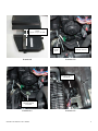
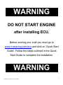
RIVA/ViPEC Engine Control Unit
PART# - RY11840-01-C
In order to achieve optimal performance gains you will need to install the following RIVA Performance Products:
Product
Part#
RIVA Performance Power Filter
RY13040
RIVA Intake Manifold Upgrade Kit
RY12040-IMUK
RIVA Supercharger Impeller
RY17040-SCI-B1 (11.5lbs of boost)
RY17040-SCI-E1 (16lbs of boost)
RIVA Power Cooler Kit - OR OEM Intercooler Upgrade Kit
RY17040-PC
RY17040-ICUK
RIVA Fuel Pressure Regulator Kit*
RY12040-RRFPR-6S5
RIVA Engine Cooling Upgrade Kit
RY10040-ECUK
* = Required to provide adequate fuel pressure.
Along with the above components we recommend many others that will compliment the RIVA/Vi-PEC ECU providing
improved performance in acceleration, handling and top speed. Please visit www.rivaracing.com/kits to review the
complete list.
- INSTALLATION INSTRUCTIONS APPLICATION(S): Yamaha FX-SHO, FZR & FZS
Required tools
Cut-off Wheel or Small Saw
Part#
N/A
Recommended tools
Service Manual
Part#
Please Call
1.
2.
3.
4.
5.
6.
7.
8.
9.
Remove start/stop lanyard.
Disconnect battery cables. NOTE: Negative (black) first. Positive (red) second.
Remove seats and rear storage bin.
Remove rear grab handle/seat support. Four bolts at center and three under grab handle. (see illustration #1)
At top of electrical box unlock tabs (2) securing cover. (see illustration #2)
Remove cover by lifting up and towards motor.
Remove bolts (4) securing stock ECU to electrical box. (see illustration #3)
Disconnect stock ECU and set aside. Retain bolts (4).
Clean inside surface of electrical box where stock ECU was located using a non-residual cleaner. Install supplied
rubber pad. (see illustration #4)
10. Connect supplied Power Connector box to ViPEC ECU. (see illustration #5)
11. Install ViPEC ECU into electrical box and secure using supplied straps (2) and stock bolts (4). (see illustration #6)
NOTE: Top of ECU must be at least 3/8” below top edge of electrical box. Apply blue Loc-tite to bolts.
Torque bolts to 5 N•m (3.7 lbf•ft).
12. Connect the stock ECU wiring harness connectors (3) to the Power Connector. (see illustration #7)
Word doc. RY11840-01-C © H1 12/2/09
1
13. Place Power Connector box on top of exhaust pipe.
14. Remove only the upper most warning sticker on electrical box cover. (see illustration #8) Clean area with a nonresidual cleaner.
15. Install supplied stainless steel cradle onto outside of electrical box cover. (see illustration #8 & 9) Secure using
supplied hardware. NOTE: Install bolts (2) from inside and nuts on outside of electrical box cover. Do not over
tighten.
16. Cut a slot in the electrical box cover using a cut-off wheel or small saw. (see illustration #9) NOTE: Sand edges so
they are smooth.
17. At lower, right side of electrical box loosen zip securing wiring harness to electrical box. (see illustration #10)
18. At lower, right side of electrical box locate black electrical connector with the black and white wires. (see illustration
#10) Disconnect and install supplied cable splicer in between. (see illustration #11)
19. While holding Power Connector above exhaust pipe carefully slide electrical box cover into place so that wiring
harness fits into cut out on electrical box cover. (see illustration #12)
20. Ensure all electrical wires are in place behind cover. Finish installing cover into place and lock tabs securing cover.
21. On back of Power Connector remove adhesive backing on Dual Lock. Carefully place Power Connector into cradle
on electrical box cover. Use Power Connector to attach Dual Lock to electrical box cover. (see illustration #13)
22. At lower, right side of electrical box tighten zip tie securing wiring harness to electrical box. (see illustration #10)
23. Inside front storage compartment remove rivets (5) securing service lid in place. NOTE: Press pin at center inward.
24. Remove service lid and locate remote control sensor. (see illustration #14)
25. Disconnect electrical connector and install supplied block-off into wiring harness connector. (see illustration #15)
NOTE: Make sure block-off ‘snaps’ into place.
26. Secure to wiring harness using supplied zip tie. (see illustration #15)
27. Replace service lid and secure using stock rivets.
28. Replace rear grab handle/seat support. Four bolts at center and three under grab handle.
29. Reconnect battery cables. NOTE: Positive (red) first. Negative (black) second.
30. WARNING: Do not start engine. Before running your craft you must go to www.rivaracing.com/ecu and click on
Quick Start Guide. Follow the steps outlined in the Quick Start Guide to complete the installation.
To register your ECU, download additional maps, software updates, and more please visit the RIVA/Vi-PECECU
Manager web site at www.rivaracing.com/ecu.
Remember, the water belongs to everyone.
Please ride responsibly and respect the environment!
Technical Support
For answers to questions regarding installation or trouble shooting RIVA Performance Products contact:
RIVA Technical Support directly at (954) 247-0705 or by e-mail at [email protected].
Limited Warranty
RIVA/ViPEC ECU’s carry a 2-year limited warranty to the original purchaser. They are warranted to be free of defects in materials and workmanship under normal use and
service. Customer modified components will be void of warranty. This warranty is limited to defects in the primary components only. Finish and/or wear marks in or on
primary components are not covered under this warranty.
RIVA Racing’s liability is expressly limited to the repair or replacement of the components contained within or associated with this kit. RIVA Racing agrees to repair or at
RIVA’s option, replace any defective unit without charge, if product is returned to RIVA Racing freight prepaid within the warranty period. Any equipment returned which, in
RIVA’s opinion, has been subjected to misuse, abuse, overheating or accident shall not be covered by this warranty.
RIVA Racing shall have no liability for special, incidental or consequential damages or injury to persons or property from any cause arising from the sale, installation or use
of this product.
No other warranty, express or implied, including, but not limited to the implied warranties of merchantability and fitness for a particular purpose, applies. Various states do
not allow for the limitation of incidental or consequential damages and therefore the above exclusion or limitation may not apply to you.
Warranty does not include the expenses related to freight or transportation of parts or compensation for any inconvenience or loss of use while being repaired. A copy of
the original invoice and a Return Authorization Number (RA#) must accompany all warranty claims.
Warranted replacement parts will be returned freight collect.
Word doc. RY11840-01-C © H1 12/2/09
2
- INSTALLATION IMAGES -
= Four exposed bolts.
= Three hidden bolts.
Depress tabs and
slide clips outwards.
Illustration #1
Illustration #2
Install pad just below
raised edge
centered between
bolt holes.
Remove
bolts (4).
Illustration #3
Word doc. RY11840-01-C © H1 12/2/09
Illustration #4
3
Place top of ECU at
least 3/8” below top
edge of electrical box.
Use supplied straps
and stock bolts to
secure ECU to
electrical box.
Illustration #5
Place top of ECU at
least 3/8” below top
edge of electrical box.
Place Power
Connector on top of
exhaust pipe.
Illustration #7
Word doc. RY11840-01-C © H1 12/2/09
Illustration #6
Remove upper warning
sticker only.
Place Power
Connector cradle just
above raised edge.
See next illustration.
Illustration #8
4
Remove material on angled
section.
(Approx. 5” long X 1-3/4” wide)
Wiring
harness
zip tie.
Illustration #9
Disconnect this
electrical connector.
Illustration #10
Slide wiring harness
into cut out.
Install supplied splicer
between electrical
connectors.
Illustration #11
Word doc. RY11840-01-C © H1 12/2/09
Illustration #12
5
Dual
Lock
Remote
Control
Sensor
Illustration #13
Illustration #14
Secure to wiring
harness with
supplied zip tie.
Supplied
block-off
installed.
Illustration #15
Word doc. RY11840-01-C © H1 12/2/09
6
WARNING__
DO NOT START ENGINE
after installing ECU.
Before running your craft you must go to
www.rivaracing.com/ecu and click on ‘Quick Start
Guide’. Follow the steps outlined in the Quick
Start Guide to complete the installation.
WARNING__
Word doc. RY11840-01-C © H1 12/2/09
7


![静電気放電シミュレータ[KES4021A/4022A]](http://vs1.manualzilla.com/store/data/006582924_2-c8b53339fcebb946ab6b00af6a3f94bc-150x150.png)