1
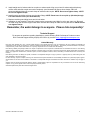
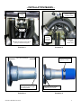
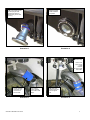
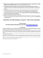
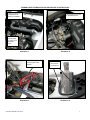
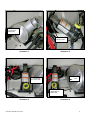
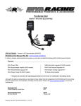
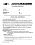
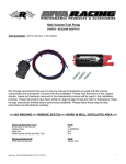
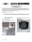
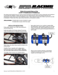
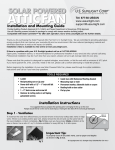
Free Flow Exhaust Kit
PART# RK16085
We strongly recommend the use of a service manual to familiarize yourself with the various components and procedures involved with
this installation. Please note that some of the original clamps, hoses and hardware removed in the disassembly process will be used
in the installation process. These instructions have been written in point form and refer to illustrations. Please follow these step-bystep instructions and illustrations carefully.
APPLICATION(S): `08~04 Kawasaki STX-12F/15F
Required Specialty Tools
Small bottle jack
Large cutting wheel/tool
Welder
Part#
N/A
N/A
N/A
Recommended Specialty Tools
1-3/4” hole saw bit
10”L x 1/4"drive extension
1/4" drive universal
5/16” x 1/4" drive socket
Part#
N/A
N/A
N/A
N/A
– INSTALLATION INSTRUCTIONS –
Read through the installation instructions entirely before beginning. As part of the installation of this kit you are
required to cut and weld aluminum.
1. Remove lanyard. Disconnect battery cables and remove battery.
2. Inside hull under rear grab handle remove air inlet tubes and disconnect hoses for stock bilge pick-ups from breather
fittings. (see illustration #1)
3. Remove exhaust hose connecting primary muffler (left water box) to secondary muffler (right water box). Disconnect
remaining hoses from breather fittings. Remove exhaust hose connecting secondary muffler to exhaust outlet. (see
illustration #2) NOTE: Retain hose clamps.
4. Remove section of foam between top deck and pump area inside hull and discard.
5. At rear of hull remove and discard plastic exhaust outlet nozzle. Remove exhaust outlet from hull. Cut exhaust outlet
5-3/4” from flange. (see illustration #3) NOTE: Sand or file rough edge after modifying.
6. Install one supplied silicone coupler onto modified exhaust outlet and secure using OE hose clamp. (see illustration
#4) Install exhaust outlet into hull and secure using stock hardware. (see illustration #5) NOTE: Be sure rubber
gasket is in place between flange and hull. Do not apply sealant to gasket. Apply blue Loc-tite to bolts. Do
not over tighten bolts.
7. Install supplied billet exhaust outlet tip using supplied hardware. (see illustration #6) NOTE: Do not use any
sealant. Use blue Loc-tite on bolts. Do not over tighten bolts.
** NOTE: To achieve optimum performance with this Free Flow Exhaust Kit we recommend the
modification outlined on pages 5 & 6 be performed at this point. Installation of the Free Flow
Exhaust Kit will be completed using the steps and illustrations on pages 5~10.
8. Thoroughly clean primary muffler outlet using a non-residual cleaner. Install second supplied silicone coupler
completely onto curved end of exhaust tube. (see illustration #5) Loosely install two OE clamps onto primary muffler
outlet and one onto coupler on exhaust outlet. TIP: Spray a generous amount of glass cleaner into couplers prior to
installing.
Word doc. RK16085 © H1 2/2/11
1
9. Install straight end of exhaust tube into coupler on exhaust outlet. Align curved end of exhaust tube with primary
muffler outlet and slide coupler onto outlet completely. (see illustration #6) Secure hose clamps. TIP: Use
recommended specialty tools to reach clamp at exhaust outlet coupler. NOTE: Do not over tighten clamp. NOTE:
Do not over tighten clamps.
10. Install hoses to stock bilge pick-ups onto breather fittings. NOTE: Route hose for rear pick-up (left side) through
Free Flow Exhaust Tube. (see illustration #6)
11. Replace remaining stock bilge hoses and air inlet tubes.
12. Installation is now complete. Thoroughly inspect engine compartment and bilge for tools, rags, parts, etc. Run craft
on stand using flush kit. After engine cools check all hoses and clamps to make sure they are secure. NOTE: Do not
over tighten clamps.
Remember, the water belongs to everyone. Please ride responsibly!
Technical Support
For answers to questions regarding installation or trouble shooting RIVA Performance Products contact:
RIVA Technical Support directly at (954) 247-0705 or by e-mail at [email protected]
Limited Warranty
RIVA Free Flow Exhaust Kits carry a 90-day limited warranty to the original purchaser. They are warranted to be free of defects in materials and
workmanship under normal use and service. Customer modified components will be void of warranty. This warranty is limited to defects in the primary
components only. Finish and/or wear marks in or on primary components are not covered under this warranty.
RIVA Racing’s liability is expressly limited to the repair or replacement of the components contained within or associated with this kit. RIVA Racing
agrees to repair or at RIVA’s option, replace any defective unit without charge, if product is returned to RIVA Racing freight prepaid within the warranty
period. Any equipment returned which, in RIVA’s opinion, has been subjected to misuse, abuse, overheating or accident shall not be covered by this
warranty.
RIVA Racing shall have no liability for special, incidental or consequential damages or injury to persons or property from any cause arising from the
sale, installation or use of this product.
No other warranty, express or implied, including, but not limited to the implied warranties of merchantability and fitness for a particular purpose, applies.
Various states do not allow for the limitation of incidental or consequential damages and therefore the above exclusion or limitation may not apply to
you.
Warranty does not include the expenses related to freight or transportation of parts or compensation for any inconvenience or loss of use while being
repaired. A copy of the original invoice must accompany all warranty claims.
Warranted replacement parts will be returned freight collect.
Word doc. RK16085 © H1 2/2/11
2
– INSTALLATION IMAGES –
Exhaust hose from
primary muffler to
secondary muffler
Breather
Tubes
Air inlet
tubes
Hoses to stock bilge outlets.
Hoses to
stock bilge
pick-ups.
Exhaust hose
from secondary
muffler to
exhaust outlet
TIP: After disconnecting tuck ends into
opening at driveline hull support.
Illustration 1
Illustration 2
Cut 5-3/4” from flange
TIP: Weld a bead around end
after cutting to prevent coupler
from sliding forward.
Illustration 3
Word doc. RK16085 © H1 2/2/11
Place worm
gear at 11 o’clock.
Top dead center of exhaust
outlet flange (12 o’clock).
Illustration 4
3
Modified exhaust
outlet installation
completed.
TIP: Insert outlet into hull.
At clamp angle outlet
upward (as shown) to
allow worm gear to clear
opening.
Illustration 5
Illustration 6
TIP: Rotate
breather fitting
Hose to rear
bilge pick-up
routed
between
exhaust tube
and muffler.
Coupler installed
completely onto
curved end of
exhaust tube.
Illustration 5
Word doc. RK16085 © H1 2/2/11
Hose clamps
loosely installed
onto muffler outlet
flange.
TIP: Make sure
exhaust tube does
not rub against
hull.
Illustration 6
4
PRIMARY MUFFLER MODIFICATION PROCEDURE:
1. At top of oil separator tank disconnect and completely remove hose connecting top of tank to front of air box. At
center of tank disconnect hose from fitting on rear of cylinder head. At bottom of tank disconnect hose from fitting on
tank. (see illustration #7) NOTE: Leave hose connected to engine. Remove oil separator tank from hull.
2. At throttle body loosen hose clamp securing air inlet tube to throttle body. (see illustration #8) At top of hull crosssection loosen the two M8 bolts securing air box to hull. Remove air box through forward engine compartment
opening by rotating 90-degrees. NOTE: Cover throttle body inlet to prevent foreign objects from entering.
3. Remove the three Phillips® head screws securing mounting plate for electrical components to hull. Carefully lay
assembly in bottom of hull under footwell. (see illustration #9)
4. Inside hull label and then remove waterlines secured to fittings at inlet of primary muffler (left water box). TIP: It will
be easier to remove waterline from lower fitting during step 6.
5. Loosen clamps securing coupler at muffler inlet/exhaust pipe joint. Slide coupler forward onto exhaust pipe joint
completely. TIP: Using a small screwdriver lift edge of coupler on exhaust pipe joint and apply glass cleaner. Move
screwdriver side to side to distribute fluid.
6. Remove muffler from hull through rear engine compartment opening. (see illustration #10) NOTE: It is necessary to
rotate muffler to ease removal through opening. Take care not to damage seal on hull. Applying a generous
amount of glass cleaner to outside of muffler and to rubber seal will ease removal.
7. Inside hull remove foam padding under front of secondary muffler (right water box). Remove rubber padding
between muffler and hull (3 pieces total). Lift muffler up onto battery tray ledge. (see illustration #11)
8. At battery tray just in front of muffler place bottle jack approximately 1” from end of muffler. (see illustrations 12 &13)
Expand jack until it is suspended between top deck and battery tray. NOTE: Position of bottle jack base is critical.
Take care not to crush electrical wires, battery strap clips and steering cable.
9. Slowly expand bottle jack to create room for muffler to move forward and up onto upper ledge of battery tray. Once
muffler is able to rest on upper ledge of battery tray retract bottle jack so that top deck rests on top of muffler. (see
illustration #14) Move bottle jack forward approximately 2-3/4” and expand until it is suspended between top deck
and battery tray. (see illustration #14) NOTE: Position of bottle jack base is critical. Take care not to crush
electrical wires, battery strap clips and steering cable.
10. Slowly expand bottle jack until muffler moves. Continue expanding bottle jack slowly while pulling on muffler until you
are able to remove completely. Once muffler is clear retract bottle jack completely and remove from hull.
11. Remove muffler from hull through rear engine compartment opening and discard. NOTE: It is necessary to rotate
muffler so as to ease removal. Take care not to damage seal on hull. Applying a generous amount of glass
cleaner to outside of muffler and rubber seal will ease removal.
12. Inside hull remove strap for secondary muffler by carefully cutting or grinding down head of rivet securing it to hull.
NOTE: Apply silicone sealant to rivet area after removing.
13. Remove end cap of primary muffler by cutting at weld. (see illustration #15) Inside muffler remove inner ring at edge.
(see illustration #16) Inside muffler drill out baffle cap using a 1-3/4” hole saw bit. (see illustrations 17 & 18) NOTE:
Sand all edges thoroughly.
14. Replace muffler end cap. Add bead around modified end of exhaust outlet. (see illustration #3) NOTE: An
experienced welder should perform this step.
15. Replace primary muffler in reverse order of steps 5~6. NOTE: It is necessary to rotate muffler so as to ease
installation. Take care not to damage seal on hull. Applying a generous amount of glass cleaner to outside
of muffler and rubber seal will ease installation.
16. Place primary muffler into cradle on left side of craft and secure strap. Slide coupler on exhaust pipe joint onto
muffler inlet flange completely. Secure hose clamps. NOTE: Do not over tighten clamps.
17. Replace brass fitting at top of muffler inlet tube with supplied brass fitting. Attach waterline from exhaust side of
cylinder to newly installed fitting and secure. Attach waterline from outlet at top of pump area to fitting at bottom of
muffler inlet and secure. (see illustration #19) NOTE: Apply pipe thread sealant to fitting. Do not over tighten
fitting. NOTE: Do not over tighten clamps.
18. Install supplied 1/2” brass splicer into waterline from intake side of cylinder and secure. Attach supplied 1/2”
waterline to splicer and secure using supplied hose clamp. (see illustration #20) NOTE: Do not over tighten
clamps.
19. Install supplied bypass fitting in a location that will allow water to be expelled so as not to come in contact with
rider(s). TIP: Choose a flat area at rear of craft. (see illustration #21) NOTE: Apply silicone sealant to flange and
threads of bypass fitting.
Word doc. RK16085 © H1 2/2/11
5
20. Attach open end of supplied 1/2” waterline to newly installed bypass fitting and secure using supplied hose clamp.
NOTE: Do not over tighten clamp. TIP: Secure spliced waterline to hull. Attach a small piece of the rubber
padding previously removed to hull support to prevent chafing. (see illustration #20)
21. Thoroughly clean primary muffler outlet using a non-residual cleaner. Install second supplied silicone coupler
completely onto curved end of exhaust tube. (see illustration #5) Loosely install two OE clamps onto primary muffler
outlet and one onto coupler on exhaust outlet. TIP: Spray a generous amount of glass cleaner into couplers prior to
installing.
22. Install straight end of exhaust tube into coupler on exhaust outlet. Align curved end of exhaust tube with primary
muffler outlet and slide coupler onto outlet completely. (see illustration #6) Secure hose clamps. TIP: Use
recommended specialty tools to reach clamp at exhaust outlet coupler. NOTE: Do not over tighten clamps.
23. Install hoses to stock bilge pick-ups onto breather fittings. NOTE: Route hose for rear pick-up (left side) through
Free Flow Exhaust Tube. (see illustration #6)
24. Replace remaining stock bilge hoses and air inlet tubes.
25. Installation is now complete. Thoroughly inspect engine compartment and bilge for tools, rags, parts, etc. Run craft
on stand using flush kit. After engine cools check all hoses and clamps to make sure they are secure. NOTE: Do not
over tighten clamps.
Remember, the water belongs to everyone. Please ride responsibly!
Technical Support
For answers to questions regarding installation or trouble shooting RIVA Performance Products contact:
RIVA Technical Support directly at (954) 247-0705 or by e-mail at [email protected]
Limited Warranty
RIVA Free Flow Exhaust Kits carry a 90-day limited warranty to the original purchaser. They are warranted to be free of defects in materials and
workmanship under normal use and service. Customer modified components will be void of warranty. This warranty is limited to defects in the primary
components only. Finish and/or wear marks in or on primary components are not covered under this warranty.
RIVA Racing’s liability is expressly limited to the repair or replacement of the components contained within or associated with this kit. RIVA Racing
agrees to repair or at RIVA’s option, replace any defective unit without charge, if product is returned to RIVA Racing freight prepaid within the warranty
period. Any equipment returned which, in RIVA’s opinion, has been subjected to misuse, abuse, overheating or accident shall not be covered by this
warranty.
RIVA Racing shall have no liability for special, incidental or consequential damages or injury to persons or property from any cause arising from the
sale, installation or use of this product.
No other warranty, express or implied, including, but not limited to the implied warranties of merchantability and fitness for a particular purpose, applies.
Various states do not allow for the limitation of incidental or consequential damages and therefore the above exclusion or limitation may not apply to
you.
Warranty does not include the expenses related to freight or transportation of parts or compensation for any inconvenience or loss of use while being
repaired. A copy of the original invoice must accompany all warranty claims.
Warranted replacement parts will be returned freight collect.
Word doc. RK16085 © H1 2/2/11
6
PRIMARY MUFFLER MODIFICATION PROCEDURE ILLUSTRATIONS:
Hose from air box to
oil separator tank.
Remove completely
Air inlet tube from air box
to throttle body inlet.
Hose from
cylinder head
to center of oil
separator
tank.
Illustration 8
Illustration 7
Electrical component
mounting plate under
footwell.
Illustration 9
Word doc. RK16085 © H1 2/2/11
TIP: Lots of
glass cleaner
and patience!
Illustration 10
7
Lift muffler up
onto ledge of
battery tray.
Bottle jack
pressure points.
Illustration 11
Illustration 12
Move jack
2-3/4”
1 inch between
jack and muffler
Lift muffler up onto
upper ledge of
battery tray.
Illustration 13
Word doc. RK16085 © H1 2/2/11
Illustration 14
8
Cut at weld all
the way around
end cap.
Remove ring
around inside
edge of muffler.
Illustration 15
Illustration 16
Do not drill any
other holes in
baffles.
Drill out baffle
cap with 1-3/4”
hole saw bit.
Illustration 17
Word doc. RK16085 © H1 2/2/11
Illustration 18
9
Supplied brass
fitting installed.
Note angle!
Waterline from
exhaust side of
cylinder.
Waterline to
stock fitting on
top of pump
inside hull.
Waterline
from intake
side of
cylinder.
Illustration 19
TIP: Prevent
chafing by
adding rubber
padding.
Waterline to
supplied
fitting at rear
of craft.
Illustration 20
Supplied bypass
fitting at rear of craft.
Illustration 21
Word doc. RK16085 © H1 2/2/11
10