1
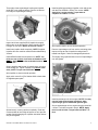
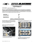
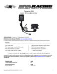
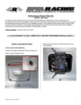
Sea-Doo XX-Charger Impeller & Housing PART# - RS17080-IH-137-060 We strongly recommend the use of a service manual to familiarize yourself with the various components and procedures involved with this installation. Please note that some of the original clamps, hoses and hardware removed in the disassembly process will be used in the installation process. These instructions have been written in point form and refer to illustrations. Please follow these step-by-step instructions and illustrations carefully. APPLICATION(S): 260/255hp model Sea-Doo’s ALLOW ENGINE TO COOL COMPLETELY BEFORE PERFORMING INSTALLATION Required Tools Torx screw adapter Impeller Shaft Holder Service Manual Part# 529 035 938 RS1750-ISH-949 219 100 313 Recommended Tools Service Mounting Plate Part# 529 035 947 IMPORTANT NOTICE: Supercharger shaft bearing degradation or failure can cause impeller to hit housing. Bearings should be inspected and or replaced prior to impeller installation. Compressor surge can cause impeller to hit housing if a blow-off valve is not used to release excess boost pressure that engine cannot process. TUNING REQUIREMENTS: Fuel: Installation of this RIVA Performance Product requires the use of RIVA Pro-Series ECU (part# RS11850-01-C). Failure to install this part will result in engine damage. Installation of this RIVA Performance Product requires the use of RIVA Pro-Series 50lb Fuel Injector Kit (part# RS12050-I-KIT-50). Failure to install this part will result in engine damage. Installation of this RIVA Performance Product requires the use of RIVA Rising Rate Fuel Pressuer Regulator Kit (part# RS12050-RRFPR-08) configured with rising rate and static pressure of 60psi. Failure to install this part will result in engine damage. - SECTION 1 INSTALLATION INSTRUCTIONS - Remove the two M6 x 35mm Torx bolts1 that secure supercharger unit to engine. Remove seats. RXP-X models remove engine cowling (5 bolts). RXT-X models remove seat bridge (4 bolts). If using a RIVA Pro-Series Aluminum Water Box proceed to next step; otherwise disconnect exhaust hose or exhaust tube from water box outlet. Loosen clamps securing coupler to water box and exhaust manifold. Carefully slide water box rearward. Remove inlet and outlet hoses attached to supercharger unit. Word doc. Part # RS17080-IH-137-060 © H1 2/18/14 1 Remove the one M6 x 35mm Torx bolt1 that secures rear of supercharger unit to engine. NOTE: You will need a special Torx adapter to remove and replace the upper/rear Torx bolt. This can be purchased through our parts department, a Sea•Doo Dealer, or a reputable tool company. Remove impeller cover and discard. NOTE: It may be necessary to tap the cover in order to remove it. Use only a dead blow mallet and tap only on tab at top of impeller cover plate. DO NOT PRY COVER OFF. Secure impeller shaft at rear of supercharger housing using a shaft holding tool. Remove impeller shaft nut1 and washer. NOTE: You must turn nut clock-wise as threads are left-handed. Remove supercharger unit from engine. NOTE: It is extremely important that the area utilized to work on the supercharger unit is very clean. Any foreign debris introduced into the supercharger unit will cause damage. It is equally important that care is taken when performing the following steps so as not to damage the impeller or working parts of the supercharger unit. Even a small mark on the impeller would ruin the dynamic balance causing severe damage. Carefully remove OEM impeller2 by twisting and pulling. NOTE: Make sure o-ring3 is in place against step collar on impeller shaft. NOTE: Before proceeding we recommend you verify slip clutch is operating properly. This should be done before disassembling supercharger unit. Please refer to your Sea•Doo service manual for procedure. Secure supercharger unit to service mounting plate and place in a securely mounted bench vise. Remove the nine M6 x 35mm Torx screws1 securing impeller cover2 to supercharger3. Inspect back of impeller if o-ring1 is not on impeller shaft. Word doc. Part # RS17080-IH-137-060 © H1 2/18/14 2 Thoroughly clean supercharger housing and impeller shaft with a non-residual cleaner. Remove all silicone from edge of supercharger housing1. Install supplied supercharger impeller cover and secure with the nine OEM M6 x 35mm Torx screws. NOTE: Apply blue Loc-tite to bolts. Torque bolts in sequence to 97lbf•in / 11 N•m. Inspect and clean supplied RIVA Impeller thoroughly taking care not to damage fins. Warm impeller using a heat gun or hair dryer. NOTE: Do not use a torch. Spin impeller shaft to ensure smooth operation. Install onto impeller shaft completely. NOTE: Supplied impeller will have machine marks left when balanced by Vortech. Remove supercharger unit from service mounting plate. Inspect o-rings at rear of impeller housing where it installs into engine. If either is damaged replace both. Install OEM flat washer and impeller nut. NOTE: You must turn nut counter clock-wise as threads are lefthanded. Apply Blue Loc-tite to threads inside of impeller nut. Thoroughly coat unpainted area on rear of supercharger unit with grease1. Secure impeller shaft at rear of supercharger unit using shaft holding tool. Tighten impeller nut (counter clockwise). NOTE: Torque nut to 22 ft•lbs / 30 N•m. Spin impeller to ensure smooth operation. Apply a thin coat of Loc-Tite Sealant 5910 to both sides of supplied spacer plate1. Install supercharger unit onto engine. NOTE: You may need to rotate supercharger impeller to allow supercharger gear to mesh with flywheel gear. Spread evenly covering surface completely. Clean any excess sealant at inner edge of spacer so as to prevent sealant from discharging into impeller area when halves are joined together. Word doc. Part # RS17080-IH-137-060 © H1 2/18/14 Secure supercharger unit to engine using the three M6 x 35mm Torx bolts removed in step 6. NOTE: Apply blue Loc-tite to bolts. Torque bolts to 97lbf•in / 11 N•m. 3 Replace water box connections. NOTE: Do not over tighten clamps. Replace supercharger outlet hose and secure. NOTE: Do not over tighten clamps. Replace seat bridge (RXT-X/RXT/GTX-SC) or engine compartment cowling (RXP-X/RXP). NOTE: Apply blue Loc-tite to bolts. Do not over tighten bolts. Check bilge for tools, rags, etc. Run craft on a flush kit to check for proper operation. Remember, the water belongs to everyone. Please ride responsibly and respect the environment! Technical Support For answers to questions regarding installation or trouble shooting RIVA Performance Products contact: RIVA Technical Support directly at (954) 247-0705 or by e-mail at [email protected]. Limited Warranty RIVA XX-Charger Impellers & Housings carry a 90-day limited warranty to the original purchaser. They are warranted to be free of defects in materials and workmanship under normal use and service. Customer modified components will be void of warranty. This warranty is limited to defects in the primary components only. Finish and/or wear marks in or on primary components are not covered under this warranty. RIVA Racing’s liability is expressly limited to the repair or replacement of the components contained within or associated with this kit. RIVA Racing agrees to repair or at RIVA’s option, replace any defective unit without charge, if product is returned to RIVA Racing freight prepaid within the warranty period. Any equipment returned which, in RIVA’s opinion, has been subjected to misuse, abuse, overheating or accident shall not be covered by this warranty. RIVA Racing shall have no liability for special, incidental or consequential damages or injury to persons or property from any cause arising from the sale, installation or use of this product. No other warranty, express or implied, including, but not limited to the implied warranties of merchantability and fitness for a particular purpose, applies. Various states do not allow for the limitation of incidental or consequential damages and therefore the above exclusion or limitation may not apply to you. Warranty does not include the expenses related to freight or transportation of parts or compensation for any inconvenience or loss of use while being repaired. A copy of the original invoice must accompany all warranty claims. Warranted replacement parts will be returned freight collect. Word doc. Part # RS17080-IH-137-060 © H1 2/18/14 4