1
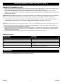
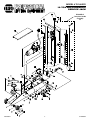
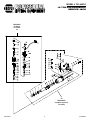
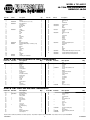
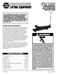
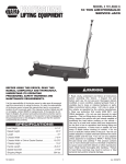
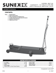
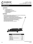
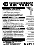
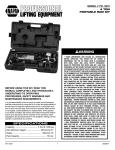
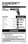
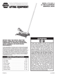
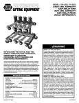
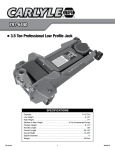
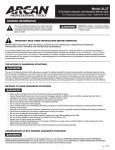
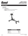
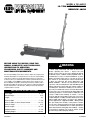
Model # 791-6620 D
10 TON AIR/HYDRAULIC
SERVICE JACK
BEFORE USING THIS DEVICE, READ THIS
MANUAL COMPLETELY AND THOROUGHLY,
UNDERSTAND ITS OPERATING
PROCEDURES, SAFETY WARNINGS AND
MAINTENANCE REQUIREMENTS.
WARNING
It is the responsibility of the device owner to make sure all personnel
read this manual prior to using the device. It is also the responsibility
of the device owner to keep this manual intact and in a convenient
location for all to see and read. If the manual or product labels are lost
or not legible, contact NAPA for replacements. If the operator is not
fluent in English, the product and safety instructions shall be read to
and discussed with the operator in the operator's native language by
the purchaser/owner or his designee, making sure that the operator
comprehends its contents.
SPECIFICATIONS
Low Height . . . . . . . . . . . . . . . . . . . . . . . . . . . . . . . . . . 6-1/4"
Raised Height . . . . . . . . . . . . . . . . . . . . . . . . . . . . . . . . . 22.5"
Length . . . . . . . . . . . . . . . . . . . . . . . . . . . . . . . . . . . . . . . . 61"
Chassis Width . . . . . . . . . . . . . . . . . . . . . . . . . . . . . . . . 7-3/4"
Chassis Width w/ Swivel Caster Bracket . . . . . . . . . . 18.375"
Chassis Height . . . . . . . . . . . . . . . . . . . . . . . . . . . . . . . . 10.5"
Handle Length . . . . . . . . . . . . . . . . . . . . . . . . . . . . . . . 45-3/4"
Saddle Diameter . . . . . . . . . . . . . . . . . . . . . . . . . . . . . . 5-7/8"
Shipping Weight . . . . . . . . . . . . . . . . . . . . . . . . . . . . . 364 lbs.
791-6620 D
1
• Read, study, understand and follow all instructions
before operating this device. • Inspect the jack
before each use. Do not use jack if damaged, altered,
modified, in poor condition, leaking hydraulic fluid, or
unstable due to loose or missing hardware or parts.
Make corrections before using. • Lift only on areas of
the vehicle as specified by the vehicle manufacturer.
• Wear eye protection that meets ANSI Z87.1 and
OSHA standards. • Do not use jack beyond its rated
capacity. • This is a lifting device only. Immediately after
lifting, support the vehicle with jack stands capable of
sustaining the load before working on the vehicle. •
Use only on a hard level surface free from obstructions
so the jack is free to reposition itself during lifting and
lowering operations. • Center load on saddle. Be sure
setup is stable before working on vehicle. • Do not
move or dolly the vehicle while on the jack. • Do not use
saddle adapters or saddle extenders between the stock
lifting saddle and the load. • Do not use any adapters
unless approved or supplied by NAPA. • Always lower
the jack slowly and carefully. • This product contains
one or more chemicals known to the State of California
to cause cancer and birth defects or other reproductive
harm. Wash hands thoroughly after handling. • Failure
to heed these warnings may result in serious or fatal
personal injury and/or property damage.
rev. 01/09/14
OPERATING MANUAL & PARTS LIST FOR 791-6620 D
Warning Information
This is the safety alert symbol. It is used to alert you
to potential personal injury hazards. Obey all safety
messages that follow this symbol to avoid possible
injury or death.
WARNING
WARNING: Indicates a hazardous situation
which, if not avoided, could result in death
or serious injury.
IMPORTANT: READ THESE INSTRUCTIONS BEFORE OPERATING
BEFORE USING THIS DEVICE, READ THIS MANUAL COMPLETELY AND THOROUGHLY, UNDERSTAND ITS OPERATING
PROCEDURES, SAFETY WARNINGS AND MAINTENANCE REQUIREMENTS.
It is the responsibility of the owner to make sure all personnel read this manual prior to using the device. It is also the responsiblity of
the device owner to keep this manual intact and in a convenient location for all to see and read. If the manual or product labels are lost
or not legible, contact NAPA for replacements. If the operator is not fluent in English, the product and safety instructions shall be read to
and discussed with the operator in the operator's native language by the purchaser/owner or his designee, making sure that the operator
comprehends its contents.
THE NATURE OF HAZARDOUS SITUATIONS
WARNING
The use of Portable Automotive Lifting Devices are subject to certain hazards that cannot be prevented by mechanical means, but only
by the exercise of intelligence, care, and common sense. It is essential to have personnel involved in the use and operation of the device
who are careful, competent, trained, and qualified in the safe operation of the device and its proper use when servicing motor vehicles
and their components. Examples of hazards are dropping, tipping or slipping of loads caused primarily by improperly securing loads,
overloading, off-centered loads, use on other than hard level surfaces, and using equipment for a purpose for which it was not intended.
METHODS TO AVOID HAZARDOUS SITUATIONS
WARNING
•
•
•
•
•
•
•
•
•
•
•
•
•
•
Read, study, understand and follow all instructions before operating this device.
Inspect the jack before each use. Do not use jack if damaged, altered, modified, in poor condition, leaking hydraulic fluid, or
unstable due to loose or missing hardware or parts. Make corrections before using.
Lift only on areas of the vehicle as specified by the vehicle manufacturer.
Wear eye protection that meets ANSI Z87.1 and OSHA standards.
Do not use jack beyond its rated capacity.
This is a lifting device only. Immediately after lifting, support the vehicle with jack stands capable of sustaining the load before working on the vehicle.
Use only on a hard level surface free from obstructions so the jack is free to reposition itself during lifting and lowering operations.
Center load on saddle. Be sure setup is stable before working on vehicle.
Do not move or dolly the vehicle while on the jack.
Do not use saddle adapters or saddle extenders between the stock lifting saddle and the load.
Do not use any adapters unless approved or supplied by NAPA.
Always lower the jack slowly and carefully.
This product contains one or more chemicals known to the State of California to cause cancer and birth defects or other
reproductive harm. Wash hands thoroughly after handling.
Failure to heed these warnings may result in serious or fatal personal injury and/or property damage.
CONSEQUENCES OF NOT AVOIDING HAZARDOUS SITUATIONS
WARNING
Failure to read this manual completely and thoroughly, failure to understand its OPERATING INSTRUCTIONS, SAFETY WARNINGS,
MAINTENANCE INSTRUCTIONS and comply with them, and failure to comply with the METHODS TO AVOID HAZARDOUS SITUATIONS
could cause accidents resulting in serious or fatal personal injury and/or property damage.
791-6620 D
2
rev. 01/09/14
OPERATING MANUAL & PARTS LIST FOR 791-6620 D
SETUP
PLEASE REFER TO THE EXPLODED VIEW DRAWING IN THIS MANUAL IN ORDER TO IDENTIFY PARTS.
1. In order to install the handle assembly item #58 in the handle socket item #36, first align the main handle tube with the largest hole in the 2.
3.
4.
5.
handle socket and the lock pin rod with the smaller hole in the handle socket.
Make sure the lock pin rod is in the down/lock position before insertion in the handle socket. Once the main handle tube and lock pin rod are aligned with their respective holes in the handle socket, push the handle assembly in the handle socket so the end of the handle tube engages the release valve mechanism in the bottom of the handle socket and the lock pin rod engages one of the three (3) locking holes in the item #1 frame.
Disengage the lock pin rod by pulling up on the lever and engaging the lever with the slot in top of the handle assembly. The handle
assembly should be free to pump up and down.
In order to check for proper handle assembly alignment with the handle socket, see if the lock pin rod will engage with the three locking holes in the frame. Also, turn the release valve knob at the top of the handle assembly left and then right to see if the release valve u-joint in front and below the handle socket is rotating simultaneously with the turning of the knob.
Before Use: Air may become trapped in the hydraulic system resulting in insufficient pump stroke, spongy pump feeling or inability to pump lift arm to maximum height. Follow the air purging instructions below:
STEP 1
a. With the release valve knob in the closed position, turn the knob in a counterclockwise direction 2 to 3 complete revolutions.
b. Depress the foot pedal 15 to 20 times.
STEP 2
a. Close the release valve knob by turning it in a clockwise direction until it stops.
b. Depress the air valve lever 6 to 8 successive times and hold it down on the last depression. If the jack's lift arm will not raise, repeat
steps 1 and 2 again.
c. If depressing the air valve will not raise the lift arm, follow step 3.
STEP 3
a. Close the release valve knob by turning it clockwise until it stops. Depress the foot pedal to raise the lift arm to its maximum height.
b. Depress the air valve while simultaneously turning the release valve 2 to 3 revolutions in a counterclockwise direction. The lift arm
should lower rapidly.
c. Close the release valve knob by turning it clockwise until it stops. Depress the air valve to see if lift arm will raise. If not, repeat step 3
several times to achieve maximum performance.
STEP 4
If the jack's lift arm will not raise by depressing the air valve, apply 4 to 5 drops of pneumatic oil in the end of the valve's quickdisconnect nipple, reattach the air line and repeat step 2. NOTE: The pneumatic oil may temporarily mist out from the air
motor's vent, but this is normal and should not be considered a leak.
OPERATING INSTRUCTIONS
This is the safety alert symbol used for the OPERATING INSTRUCTIONS section of this manual to alert you to potential
personal injury hazards. Obey all instructions to avoid possible injury or death. IMPORTANT: Before attempting to raise any vehicle, check vehicle service manual for recommended lifting surfaces.
OPERATION:
1.
2.
To raise load: Turn the knob at the top of the handle assembly in a clockwise direction until tight. . Position the jack under the
load. Proceed to pump the handle in order to raise the lift arm to the load. As the saddle at the end of the lift arm gets closer to
the load, reposition the jack so the saddle will contact the load firmly and the load is centered on the saddle. Make sure the
saddle is correctly positioned. Raise the load to the desired work height. Place jack stands of appropriate capacity at the vehicle
manufacturers's recommended support areas that provide stable support for the raised vehicle. DO NOT CRAWL UNDER
VEHICLE WHILE LIFTING VEHICLE OR PLACING OR REMOVING THE JACK STANDS! Once jack stands are positioned,
turn the jack handle VERY SLOWLY in a counterclockwise direction to lower the load to rest on the jack stands. Inspect the
relationship between the jack stands and load to make sure the setup is stable and safe. If the setup is not stable or safe, follow
the preceding steps until corrected.
To lower load: Follow the procedures mentioned in "To raise load" section of the OPERATING INSTRUCTIONS in order to raise the load off the jack stands. Once the load has cleared the jack stands, remove the jack stands from under the load and away from the work area. Turn handle very slowly in a counterclockwise direction until the load is completely lowered to the ground. Once the jack's lifting saddle has cleared the load, remove the jack from under the load. CAUTION: Keep hands and feet away from the hinge mechanism of the jack.
PREVENTATIVE MAINTENANCE
This is the safety alert symbol used for the PREVENTATIVE MAINTENANCE section of this manual to alert you to potential personal injury hazards. Obey all instructions to avoid possible injury or death.
IMPORTANT: The number one cause of jack failure in air/hydraulic jacks is dirt and moisture in the air motor and/or hydraulic system.
The shop air supply should be equipped with water and dirt filter traps that should be emptied or cleaned according to a monthly
maintenance schedule. An in line oil lubricator will extend the life of air/hydraulic jacks. Inoperable jacks caused by poorly equipped or
maintained shop air systems are not eligible for warranty consideration. Contaminants can also enter the air/hydraulic system when
the shop air line is disconnected from the jack air line and the line is dropped on the floor. Contaminants in the air couplers, once reconnected,
will be driven into the system.
791-6620 D
3
rev. 01/09/14
OPERATING MANUAL & PARTS LIST FOR 791-6620 D
PREVENTATIVE MAINTENANCE (CONT.)
1.
2.
Always store the jack in a well protected area where it will not be exposed to inclement weather, corrosive vapors, abrasive dust, or any other harmful elements. The jack must be cleaned of water, snow, sand or grit before using.
The jack must be lubricated periodically in order to prevent premature wearing of parts. A general purpose grease must be
applied to all zerk grease fittings, caster wheels, front axle wheels, elevator arm, handle base pivot bolts, release mechanism and all other bearing surfaces.
IMPORTANT: Any jack found to be defective as a result of worn parts due to lack of lubrication or air/hydraulic system contaminated
with water, rust and/or foreign materials from the air supply or other outside source is not eligible for warranty consideration.
3. It should not be necessary to refill or top off the reservoir with hydraulic fluid unless there is an external leak. An external leak requires immediate repair which must be performed in a dirt-free environment by an authorized service center.
IMPORTANT: In order to prevent seal damage and jack failure, never use alcohol, hydraulic brake fluid or transmission oil in the jack.
4.
5.
6.
Every jack owner is responsible for keeping the jack labels clean and readable. Use a mild soap solution to wash external sur
faces of the jack but not any moving hydraulic components.
Inspect the jack before each use. Do not use the jack if any component is cracked, broken, bent, shows sign of damage or leaks hydraulic fluid. Do not use the jack if it has loose or missing hardware or components, or is modified in any way. Take corrective action before using the jack again.
Any hydraulic repairs within the warranty period must be performed by an authorized service center.
TROUBLESHOOTING
Problem
Action
1. Unit will not lift load.
Purge air from hydraulic system by following procedure under SETUP.
2. Unit will not sustain load or feels “spongy” under load.
Purge air from hydraulic system as above.
3. Unit will not lift to full height.
Purge air from hydraulic system as above.
4. Handle tends to raise up while the unit is under load.
Pump the handle rapidly several times to push oil past ball valves in
power unit.
5. Unit still does not operate.
For a complete list of authorized hydraulic repair centers,
please visit www.toolwarrantyrepair.com
WARRANTY
Please contact your local NAPA Auto Parts Store for details on warranty.
791-6620 D
4
rev. 01/09/14
Model # 791-6620 D
10 Ton AIR/HYDRAULIC
SERVICE JACK
RS6620B41
Complete Handle
Assembly
58
791-6620 D
5
rev. 01/09/14
Model # 791-6620 D
10 Ton AIR/HYDRAULIC
SERVICE JACK
RS6620DA
Air Motor
Assembly
64
59
RS6620D59
Complete Hydraulic
Assembly
791-6620 D
6
rev. 01/09/14
Model # 791-6620 D
10 Ton AIR/HYDRAULIC
SERVICE JACK
Index No.
Part No.Description
1
2
3
RS660903BL
3-1
RS660903A
4
5
6
7
8
RS660908Y
9
10
11
12
13
14
15
16
17
18
19
RS660916BL
20
RS660917
21
22
23
24
25
26
27
28A
29
RS660929
30
RS550510
Frame
Washer
Front Wheel (incl. #2, 3, 3-1, 4,5)
Roller Bearing Set
Snap Ring Grease Fitting
Rod Link
Bolt
Saddle
Lock Washer Nut
Spring
Bolt Bolt Snap Ring Shaft
Washer
Ring Nut Rear Wheel Assembly
Caster Bolt Kit Assembly - incl. #20 (2), 21 (2) Washer Washer Bolt Snap Ring Shaft
Washer Pin
Link Assy.
Spring
Snap Ring -12 mm Diameter
Index No.
Qty.
Part No.Description
31
RS550509
32
33
35
36
RS660932BL
37
RS550511BL
38
39
40
RS550535
41
42
43
RS660939Y
44
45
46
47
48
49
50
51
RS6614A51
52
53
54
55
56
57
58
RS6620B41
59
RS6620D59
RS6620DLK
1
4
2
2
2
5
2
2
1
2
2
1
1
2
2
1
2
2
2
2
2
4
4
4
2
1
1
1
1
1
2
Parts list for HYDRAULIC UNIT: RS6620D59
Index No. Part No.Description
1
*
2
*
3
*
4
5
*
6
*
7
*
8
*
9
*
10
11
*
12
*
13
*
14
*
15
16
*
17
18
*
19
*
Snap ring Washer
O-ring
Piston Rod
Piston ring
Sealing washer
O-ring
O-ring Retainer
Snap ring
Oil cylinder assembly
Oil Filler Plug
Steel ball
Ball seat
Spring
Screw
Sealing washer
Bolt
Steel ball
Copper washer
Qty.
Index No. Part No.Description
20
21
*
22
*
23
*
24
RS6620D24
29
*
30
*
31
A
B
*
C
*
D
*
E
*
F
G
H
*
I
*
J
K
RS6614AK
1
2
1
1
1
1
1
1
1
1
2
1
1
1
1
1
1
1
1
Bolt
Steel ball
O-ring
O-ring
Release valve Rod Revision D
O-ring
Washer
Cylinder Pump Plunger
Screw
Copper washer
Spring
Steel Ball 9
Steel Ball 6
Oil box
Screw
Washer
Washer
Nut
Hose (incl. J, K (2))
Parts list for Air motor: RS6620DA
Index No. Part No.Description
32
**
33
RS6620BA33
34
**
35
36
**
37
**
38
**
39
40
41
42
**
43
44
45
46
47
48
Copper washer
Oil valve assembly
Nylon Gasket
Pump cylinder
Oil seat
Nylon Gasket
Copper washer
Nut
Bolt
Front cover
Steel Ball 3 Air Pump Housing
Nut
Spring
Washer
Cylinder Pump Plunger
Piston Body "A"
Qty.
Index No. Part No.Description
2
1
1
1
1
1
1
1
8
1
4
1
1
1
1
1
1
49
**
O-ring
50
Air Release Rod
51
**
O-ring
52
Piston Body "B"
53
Bolt
54
Air Seal Revision D
55
**
O-ring
56
**
O-ring
57
Rear cover
58
pin
59
**
O-ring
60
screw
61
RS6620B61
Air valve (excluding hose)
62
O-ring
63
**
Nylon washer
64
RS6620DA
Air Motor Assembly Revision D
65
RS6620B65
Hose
Only index numbers identified by Part Number are available separately. * Only available in hydraulic repair kit RS6620DHRK. ** Only available in air motor repair kit RS6620DARK.
791-6620 D
7
Qty.
Pedal Pin
Pin Revision D
Pin
Cover Board
Handle Socket
Pedal
Nut Washer Bolt Kit (Incl. 38, 39, 40)
Handle
Sleeve
Knob (incl. 43, 44)
Pin Control Rod
Spring
Washer
Screw
Rod Joint
Spring
Release Assembly Revision D
Convey Rod
Washer
Pin
Pin
Washer
Ring
Complete Handle Assembly (incl. 41-49, 52-56)
Complete Hydraulic Assembly Revision D
Product Label Kit (not shown) Revision D
1
1
1
1
1
1
1
1
1
1
2
1
1
1
1
2
2
1
1
1
1
1
2
1
1
2
1
1
1
Qty.
1
1
1
1
1
2
2
1
1
1
1
1
1
1
1
1
1
2
1
Qty.
2
1
2
1
3
1
2
1
1
1
2
1
1
3
2
1
1
rev. 01/09/14