1
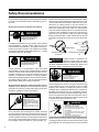
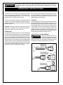
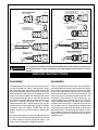
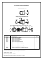
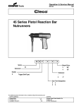
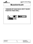
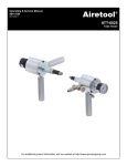
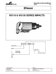
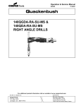
Operation & Service Manual
823049
6/01
CH SERIES CHIPPERS
CH
-
- XX - X
XX
Series:
CH
Stroke:
22
2 1/4
32
3 1/4
Nose Type :
RD
Round
HX
Hexagon
Retainer :
H
Standard for CH Models Only
C
Cleco Type for CH Models Only
Q
Quick Change for CH Round Collar Chisels Only
NORTH AMERICA
EUROPE
CooperTools
P.O. Box 1410
Lexington, SC 29071
Cooper Power Tools GmbH & Co.
Postfach 30
D-73461 Westhausen
1
Safety Recommendations
For your safety and the safety of others, read and understand
the safety recommendations before operating any percussion tool.
Always wear protective equipment and clothing.
!
WARNING
Impact resistant eye protection
must be worn while operating
or working near this tool.
throttle moves freely and returns to closed position). Being
careful not to endanger adjacent personnel, clear the air hose
of accumulated dust and moisture. Attachment of a quickdisconnect air coupling directly to the inlet threads of a
percussion tool can cause wear and failure of the coupling.
Should the coupling fail, severe injury can result from the
hose end violently whipping about. If a quick-disconnect air
coupling is used, separate the coupling from the tool with a
whip hose (1.5 feet minimum). Only use a whip hose with
fittings of hardened steel or other material which is at least
comparably resistant to shock. Do not use hose to lift or lower
tool.
For additional information on eye protection, refer to Federal
OSHA Regulations, 29 CFR, Section 1910.133, Eye and
Face Protection, and ANSI Z87.1, Occupational and Educational Eye and Face Protection. This standard is available
from the American National Standards Institute, Inc., 11 West
42nd Street, New York, NY 10036.
!
CAUTION
Personal hearing protection is
recommended when operating
or working near this tool.
Hearing protection is recommended in high noise areas
(above 85 dBA). Close proximity of additional tools, reflective
surfaces, process noises, and resonant structures can substantially contribute to the sound level experienced by the
operator. For additional information on hearing protection,
refer to Federal OSHA Regulations, 29 CFR, Section 1910.95,
Occupational Noise Exposure, and American National Standards Institute, ANSI S12.6, Hearing Protectors.
Gloves and other protective clothing should be worn as
required. Properly fitted gloves cushion vibration and protect
the fingers from pinching, scuffing and scraping and must be
used when guiding the chisel on a workpiece.
!
WARNING
Compressed air hazard.
Compressed air can cause loss
of eyesight, bleeding or injection
of foreign material into the body
or blood.
Never use compressed air to clean
off clothing or direct it at any person.
Cleco percussion tools are designed to operate on 90 psig
(6.2 bar) maximum air pressure. Excessive air pressure can
damage the plunger and increases sound levels. Installation
of a filter-regulator-lubricator in the air supply line ahead of the
tool is highly recommended. Before the tool is connected to
the air supply, check the throttle for proper operation (i.e.,
2
Whip Hose
Coupling Nipple
Coupling Nipple
Quick Disconnect Coupling
Do not use!
Quick Disconnect Coupling
OK
Cracked chisels or implements are
hazardous. Visually inspect the chisel
or implement for cracks before use. Make a practice of having
all chisels magnifluxed before resharpening. Destroy and
discard any chisel or implement that shows a crack.
!
WARNING
!
WARNING
Explosive Hazard.
Use only nonsparking chisels or
implements in explosive or
flammable environments.
Correct selection of the chisel or other implement is important. Dull edges on the chisel or moil point cause the energy
of the percussion blow to be absorbed by the tool itself,
instead of the workpiece, increasing the chance of chisel
breakage. When operating percussion tools in explosive or
flammable environments, use only non-sparking chisels or
implements such as those made from beryllium copper. Also,
do not use cupped rivet sets with Cleco percussion tools to
drive nails. Blows not centered on the nail can cause the nail
to ricochet off the work and strike the user.
!
WARNING
Impact Hazard. Ejected chisels can cause
serious injury or even death.
Disconnect air before changing chisels.
Do not operate unless chisel is in contact
with workpiece.
Do not point tool in direction of any person.
Use safety retainers on tool and retainer
type chisels.
Erect barriers to protect persons in
surrounding or lower work areas.
Before removing a tool from service, after completing a job,
or changing chisels or other bits, make sure the air line is shut
off and drained of air. This will prevent the tool from operating
if
Safety Recommendations
the throttle is accidently engaged. Use of a self-relieving
valve within reach of the user of the tool is highly recommended.
INDIVIDUAL WORK STATION
Self-Relieving
Valve
Regulator
Lubricator
0
45
90
Coupling
Filter
Hose
Quick Disconnect
Coupling
Tool
Do not operate or trigger any percussion tool unless the
chisel, scaling tool, rivet set, or other implement is in the tool
and in contact with the workpiece or worksurface. Never point
any percussion tool in the direction of another person or
yourself, or deliberately eject a chisel. Failure to do so can
cause serious injury and/or damage the tool.
Chisel or rivet set retainers are recommended and furnished
as standard equipment. Periodic inspection of the retainer
for wear or damage is recommended since these devices
can receive heavy abuse, particularly if the tool is run off
the workpiece. Damaged retainers are dangerous, and
can allow the ejection of a chisel or other implement.
They must be replaced as necessary. Only use safety
retainer type chisels, as shown in the operating instructions and service manual. Also, it is good safety practice to
erect suitable barriers to protect persons in surrounding or
lower work areas from possible ejected tools.
Some individuals
may be susceptible to disorders
of the hands and
arms when performing tasks
Repetitive work motions and/or vibration
consisting
of
may cause injury to hands and arms.
highly
repetitive
Use minimum hand grip force.
Keep body and hands warm and dry.
motions and/or
Avoid anything that inhibits blood circulation.
exposure to exAvoid continuous vibration exposure.
tended vibration.
Keep wrists straight.
Avoid repeated bending of wrists and hands.
Cumulative
trauma disorders
such as carpal tunnel syndrome and tendonitis may be
caused or aggravated by repetitious, forceful exertions of the
hands and arms. Vibration may contribute to a condition
called Raynaud’s Syndrome. These disorders develop gradually over periods of weeks, months, and years. It is presently
unknown to what extent exposure to vibrations or repetitive
motions may contribute to the disorders. Hereditary factors,
vasculatory or circulatory problems, exposure to cold and
dampness, diet, smoking and work practices are thought to
!
WARNING
contribute to the conditions. Any user suffering prolonged
symptoms of tingling, numbness, blanching of fingers, clumsiness or weakened grip, nocturnal pain in the hand, or any
other disorder of the shoulders, arms, wrists, or fingers is
advised to consult a physician. If it is determined that the
symptoms are job related or aggravated by movements and
postures dictated by the job design, it may be necessary for
the employer to take steps to prevent further occurrences.
These steps might include, but are not limited to, repositioning the workpiece or redesigning the workstation, reassigning
workers to other jobs, rotating jobs, changing work pace, and/
or changing the type of tool used so as to minimize stress on
the operator. Some tasks may require more than one type of
tool to obtain the optimum operator/tool/task relationship.
BAD POSTURE
GOOD POSTURE
• Tasks should be performed in such a manner
that the wrists are maintained in a neutral
position, which is not flexed, hyperextended,
or turned side to side.
• Stressful postures should be avoided. Select
a tool appropriate for the job and work
location.
Work gloves with vibration reducing liners and wrist supports
are available from some manufacturers of industrial work
gloves. Tool wraps and grips are also available from a
number of different manufacturers. These gloves, wraps, and
wrist supports are designed to reduce and moderate the
effects of extended vibration exposure and repetitive wrist
trauma. Since they vary widely in design, material, thickness,
vibration reduction, and wrist support qualities, it is recommended that the glove, tool wrap, or wrist support manufacturer be consulted for items designed for your specific application. Proper fit of gloves is important. Improperly fitted
gloves may restrict blood flow to the fingers and can
substantially reduce grip strength.
This information is a compilation of general safety practices
obtained from various sources available at the date of production. However, our company does not represent that
every acceptable safety practice is considered herein, or that
abnormal or unusual circumstances may not warrant or
require additional procedures. Your work may require additional specific safety procedures. Follow these procedures as
required by your company. For more information, see the
latest edition of ANSI B186.1, Safety Code for Portable Air
Tools, available from the American National Standards Institute, Inc., 11 West 42nd Street, New York, NY 10036.
3
!
WARNING
Eye protection must be worn when disassembling tool or when air line is turned on. A
self-relieving valve in close proximity to the repair station to bleed off air is recommended.
OPERATING INSTRUCTIONS
The CLECO "CH" series chipper is designed to operate
on 90 psig air pressure using a 1/2" I.D. hose up to 8' in
length. If additional length is required, a 3/4" I.D. or large
hose should be connected to the 1/2" hose.
If the operation of the chipper becomes sluggish or erratic,
pour one teaspoon of kerosene into the air inlet and
operate the tool for a few seconds. Lubricate the tool as
explained above after flushing.
The air hose should be cleared of accumulated dirt and
moisture, then one-half (1/2) teaspoon of 10W machine oil
should be poured into the tool's air inlet before connecting
the hose to the tool.
STORAGE
In the event that it becomes necessary to store the tool for
an extended period of time (overnight, weekend, etc.), it
should receive a generous almount of lubrication at that
time and again when returned to service. Store the tool in
a clean and dry environment. Alternatively, chippers and
scalers may be put in a bucket of kerosene or light oil for
extended periods of storage such as weekends or plant
shutdowns. The tool should always be lubricated before
storage and when being returned to service.
Important: The handle should be checked after the first
eight hours of operation and occasionally thereafter to
make sure it is tight. Torque to 300 ft. lbs.
LUBRICATION
An automatic in-line filter-lubricator is recommended as it
increases tool life and keeps the tool in sustained operation. The in-line lubricator should be regularly checked and
filled with a good grade of 10W machine oil. Never use a
heavy oil, as this will cause a loss of efficiency. Proper
adjustment of the in-line lubricator is performed by placing
a sheet of paper next to the exhaust ports and holding the
throttle open for approximately 30 seconds. The lubricator
is properly set when a light stain of oil collects on the paper.
Excessive amounts of oil should be avoided.
CHISEL INSTALLATION & REMOVAL
Turn off the air and drain the air
! WARNING hose before installing or removing
any chisel or implement. Follow the
procedure below and on next page for installing any chisel
or implement. Reverse the procedure for removal.
STANDARD RETAINER
CHISEL
INSERT CHISEL INTO
RETAINER AND ROTATE
RETAINER 1/4 TURN
(90°) IN EITHER DIRECTION.
INSTALL RETAINER WITH
CHISEL ONTO BARREL WHILE
ALIGNING SLOT IN RETAINER
WITH GROOVE ON BARREL.
RETAINER
GROOVE
BARREL
SLOT
LOCK SPRING
INSERT SPRING INTO SLOT
IN RETAINER UNTIL ONLY
TAB ON SPRING IS EXPOSED.
4
TAB
OPTIONAL QUICK CHANGE RETAINER FOR ROUND COLLARED CHISEL ONLY
OPTIONAL CLECO TYPE RETAINER
INSTALL RETAINER ON BARREL.
ALIGN SLOT IN RETAINER WITH
GROOVE ON BARREL.
INSTALL RETAINER ONTO BARREL
WITH SLOT IN RETAINER AND
GROOVE ON BARREL IN ALIGNMENT.
BARREL
BARREL
GROOVE
SLOT
RETAINER
RETAINER
SLOT
INSERT SPRING INTO SLOT
IN RETAINER UNTIL ONLY
TAB ON SPRING IS EXPOSED.
CHISEL
RELEASE COLLAR
GROOVE
LOCK SPRING
LOCK SPRING
INSERT SPRING INTO SLOT IN
RETAINER UNTIL ONLY TAB
ON SPRING IS EXPOSED.
TAB
INSERT CHISEL INTO RETAINER
UNTIL LATCH SPRING RISES.
ROTATE CHISEL 1/4 TURN (90°)
IN EITHER DIRECTION.
PULL RELEASE COLLAR BACK
AND INSERT CHISEL.
CHISEL
RELEASE COLLAR SHOULD RETURN TO
ORIGINAL LOCATION WHEN COLLAR OF
CHISEL IS BEHIND BALLS IN RETAINER.
RETAINER AND CHISEL
ARE NOW LOCKED INTO
POSITION.
!
WARNING
TAB
Eye protection must be worn when disassembling tool or when air line is turned on. A
self-relieving valve in close proximity to the repair station to bleed off air is recommended.
SERVICE INSTRUCTIONS
DISASSEMBLY
REASSEMBLY
To disassemble the tool, place the flats of the barrel in a
vise with the handle, No. 833157, facing upward. Using a
pair of spreader pliers, spread the exhaust deflector, No.
834674, open and slip it down on the barrel far enough to
allow the handle locking ring to be disengaged from the
handle. Unscrew the handle from the barrel and remove
the valve block button, No. 832172, valve, No. 832195, and
valve block, No. 832506. Remove the barrel from the vise
and invert it, allowing the plunger to fall out. To disassemble the throttle valve, unscrew throttle valve cap, No.
833155, and remove the throttle valve spring, No. 834852,
and throttle valve, No. 834854. Throttle valve pin, No.
834853, will drop out of throttle valve pin bushing, No.
832210.
The tool is reassembled in the reverse order of disassembly. Wash all parts thoroughly in a solvent before reassembly. Prepare the threads on the barrel and in the handle
with a high grade thread lubricant before assembling.
Make sure the threads are clean before lubricating. The
handle, No. 833157, should be torqued to 300 ft. lbs. After
reassembly, place teaspoon of 10W machine oil in the
handle bushing before attaching the air hose. This will
insure immediate lubrication of all parts as soon as the air
is applied. After the air hose is connected to the tool and
the air supply turned on, there should be a slight amount
of free play in the throttle lever, No. 834855, lack of which
will allow the tool to run without being throttled. If no free
play is evident, the flat end of the throttle valve pin should
be ground off until there is a small amount of free play in
the throttle lever.
Remove handle bushing, No. 833471, and wash the inlet
screen in a solvent. Blow air through the screen in reverse
of normal air flow to remove any foreign matter. If the
screen is torn or damaged, it should be replaced.
5
"CH" SERIES CHIPPER RETAINERS
STANARD RETAINER - 833163
833163
839033
OPTIONAL CLECO TYPE RETAINER - 831847
834776
834774
834775
839033
QUICK CHANGE RETAINER FOR ROUND COLLAR CHISEL ONLY - 831861
834872
834874
PART NO.
833163
834774
834775
834776
834871
834872
834873
834874
834875
834876
834877
839033
834873
834876
NAME OF PART
Standard Retainer (incl. 839033)
Optional Cleco Type Retainer
Optional Cleco Type Latch Spring
Optional Cleco Type Latch
Optional Quick Change Retainer Body
Optional Quick Change Retainer Sleeve
Optional Quick Change Retainer Spring
Optional Quick Change Retainer Release Collar
Optional Quick Change Retainer "O"-Ring
Optional Quick Change Retainer Ball
Optional Quick Change Retainer Lock Spring
Standard and Optional Cleco Type Retainer Lock Spring
The Retainer subassemblies can be purchased using these Part Numbers:
Standard Retainer — 833163
Optional Cleco Type Retainer — 831847
Optional Quick Change Retainer for Round Collar Chisel Only — 831861
6
834877
834871
834875
QTY.
1
1
1
1
1
1
1
1
1
6
1
1
7
PART NO.
203185
203419
832125
832172
832195
832210
832215
832506
832540
832726
832964
832965
833155
833157
833471
834276
834293
834674
834852
834853
834854
834855
834856
834857
836178
843656
844306
869975
NAME OF PART
Warning Label
Warning Label
Throttle Lever Pin
Valve Block Button
VaIve
Throttle Pin Bushing
Handle Locking Ring
Valve Block
Throttle Lever Stop Pin
Valve Block Dowel Pin
Tool Nose (Std. - Round)
Tool Nose (Opt. - Hex)
Throttle Valve Cap
Handle (incl. 832210, 836178)
Inlet Bushing
CH-32 Plunger
CH-22 Plunger
Exhaust Deflector
Throttle Valve Spring
Throttle Valve Pin
Throttle Valve
Throttle Lever
CH-22 Barrel
CH-32 Barrel
Handle Bushing
Air Inlet Screen
"O''- Ring 5/16" (7.49mm) x 7/16" (11.11mm)
Warning Tag
The complete handle can be purchased as a subassembly. Code No. 831373.
8
QTY.
1
1
1
1
1
1
1
1
1
2
1
1
1
1
1
1
1
1
1
1
1
1
1
1
1
1
1
1
NOTES
9
NOTES
10
NOTES
11
CooperTools
670 Industrial Drive
Lexington, SC 29072
Phone: (803) 359-1200
Fax: (803) 359-2013
www.cooperindustries.com
12