1
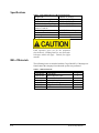
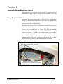
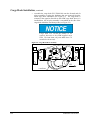
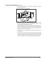
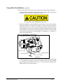
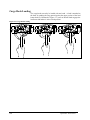
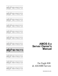
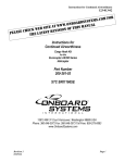
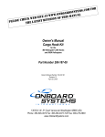
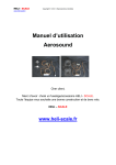
Owner's Manual Cargo Hook Kit for the Eurocopter EC135 Kit Part Number 200-375-00 Owner's Manual Number 120-143-00 Revision 1 December 16, 2011 13915 NW 3rd Court, Vancouver, WA 98685 USA Phone: 360-546-3072 Fax: 360-546-3073 Toll Free: 800-275-0883 www.OnboardSystems.com This page intentionally left blank. RECORD OF REVISIONS Revision Date Page(s) 0 06/17/11 All 1 12/16/11 Section 2 Reason for Revision Initial Release Updated installation instructions to reflect most efficient procedures. Register Your Products for Automatic Notifications Onboard Systems offers a free notification service via fax or email for product alerts and documentation updates. By registering your Onboard Systems products at our website, we will be able to contact you if a service bulletin is issued, or if the documentation is updated. You can choose to receive notices on an immediate, weekly, or monthly schedule via fax, email or both methods. There is no charge for this service. Please visit our website at www.onboardsystems.com/notify.php to get started. ii This page intentionally left blank. CONTENTS Section 1 General Information Introduction, 1-1 Safety Labels, 1-1 Specifications, 1-2 Bill of Materials, 1-2 Theory of Operation, 1-3 Section 2 Installation Instructions Cargo Hook Installation, 2-1 Installation Check-Out, 2-7 Component Weights and CG, 2-7 Paper Work, 2-7 Section 3 Operation Instructions Operating Procedures, 3-1 Cargo Hook Rigging, 3-2 Cargo Hook Loading, 3-4 Section 4 Maintenance Instructions for Returning a System to the Factory, 4-1 Section 5 Certification FAA STC, 5-1 Transport Canada Approval, 5-3 EASA STC, 5-4 iii This page intentionally left blank. Section 1 General Information Introduction Cargo Hook Kit P/N 200-375-00 is a single cargo hook kit for installation on the Eurocopter EC135. This cargo hook kit replaces the Eurocopter installed cargo hook in the single hook cargo hook configuration and uses the Eurocopter installed external cargo hook suspension beam and fixed provisions including the cargo hook electrical release system and the mechanical release system within the cockpit. The P/N 200-375-00 single cargo hook kit is compatible with the Eurocopter installed cargo hook P/N AS21-8, AS21-17, or AS22-38-20. Safety Labels The following definitions apply to safety labels used in this manual. Indicates a hazardous situation which, if not avoided, will result in death or serious injury. Indicates a hazardous situation which, if not avoided, could result in death or serious injury. Indicates a hazardous situation which, if not avoided, could result in minor or moderate injury. Draws the reader’s attention to important or unusual information not directly related to safety. Used to address practices not related to personal injury. General Information 1-1 Specifications Table 1.1 P/N 528-041-00 Cargo Hook Specifications Design load Design ultimate strength Electrical release capacity Mechanical release capacity Force required for mechanical release at 3,000 lb. Electrical requirements Minimum release load Unit weight Mating electrical connector 3,000 lbs. (1,360 kg.) 11,250 lbs. (5,103 kg.) 7,500 lbs. (3,402 kg.) 7,500 lbs. (3,402 kg.) 8 lb. max. (.600” travel) 22-32 VDC 6.9 – 10 amps 0 pounds 3.67 lbs (1.66 kg.) PC06A8-2S SR Load capacities given are for the equipment described only. Loading limits for your particular helicopter model still apply. Consult your flight manual. Bill of Materials The following items are included with the Cargo Hook Kit, if shortages are found contact the company from whom the system was purchased. Table 1.2 Bill of Materials Part Number Description 528-041-00 268-053-00 270-190-00 120-143-00 121-057-00 122-025-00 123-037-00 1-2 Cargo Hook Manual Release Cable Electrical Release Harness Owner’s Manual Flight Manual Supplement Cargo Hook Service Manual ICA Maintenance Manual Quantity 1 1 1 1 1 1 1 General Information Theory of Operation The primary elements of the Cargo Hook are the load beam, the internal mechanism, and a DC solenoid. The load beam supports the load and is latched through the internal mechanism. The DC solenoid and an external manual release cable provide the means for unlatching the load beam. A load is attached to the load beam by passing the cargo sling ring into the throat of the load beam and pushing the ring against the upper portion of the load beam throat, which will initiate the hook to close. In the closed position, a latch engages the load beam and retains it in this position. To release the load, the latch is disengaged from the load beam. With the latch disengaged, the weight of the load causes the load beam to swing to its open position, and the cargo sling slides off the load beam. The load beam then remains in the open position awaiting the next load. A load release can be initiated by three different methods. Normal release is achieved by pilot actuation of the push-button switch in the cockpit. When the push-button switch is pressed, it energizes the DC solenoid in the Cargo Hook, and the solenoid opens the latch in the internal mechanism. In an emergency, release can be achieved by operating a mechanical release cable. The release cable operates the internal mechanism of the Cargo Hook to unlatch the load beam. The load can also be released by the actuation of a lever located on the side of the Cargo Hook. General Information 1-3 This page intentionally left blank. Section 2 Installation Instructions These procedures are provided for the benefit of experienced aircraft maintenance facilities capable of carrying out the procedures. They must not be attempted by those lacking the necessary expertise. Cargo Hook Installation Disconnect the manual release cable from the existing OEM installed cargo hook. Remove the external section (up to the belly connection) of the manual release cable, noting its routing as the Onboard Systems manual release cable will duplicate this. Disconnect the existing electrical release harness from the cargo hook and remove the external section (up to the belly connection). Remove the existing OEM installed cargo hook from the beam by removing the bolts that secure the forward and aft bearing housings (Eurocopter P/N AS22-38-20-02 and AS22-38-20-04) to the beam support structure (see below). Separate the cargo hook from the pivot assemblies by removing the two bolts and associated washers and nuts at each end. Retain all fasteners and the pivot assemblies as these will be used with the Onboard Systems cargo hook. Temporarily label the aft and fwd pivot assemblies for re-assembly onto the Onboard Systems cargo hook. Figure 2.1 OEM Cargo Hook Removal 1. Remove these bolts and remove cargo hook and pivot assemblies from beam. 2. Separate cargo hook from pivot assemblies by removing these two bolts at each end of cargo hook. Installation Instructions 2-1 Cargo Hook Installation, continued o Assemble the cargo hook P/N 528-041-00 onto the forward and aft pivot assemblies re-using the hardware that was removed from the OEM cargo hook installation (see Figure 2.2). The cargo hook is oriented in the opposite direction as the OEM cargo hook when it is installed thus the aft pivot assembly is assembled on the side of the cargo hook which the load beam points (see Figure 2.2). Cargo hook P/N 528-041-00 installs in the opposite direction as the OEM installed cargo hook. The load beam will point AFT when it is installed on the aircraft. Figure 2.2 Cargo Hook/Pivot Assembly Aft Load Beam 2-2 Installation Instructions Cargo Hook Installation, continued o Remove the manual release cover from the cargo hook by removing three screws (see below). Figure 2.3 Manual Release Cover Removal Remove these three screws. Manual Release Cover Installation Instructions o Thread the manual release cover onto the end of the manual release cable until the threads protrude into the inside of the cover (i.e. – full thread engagement) and tighten the jam nut. o Hold the manual release cover near the cargo hook, position the inner cable of the manual release cable between the fork fitting (reference figure 2.6), and then secure the manual release cover to the cargo hook using the three screws removed earlier. o Install the electrical release harness (P/N 270-190-00) connector onto the cargo hook. o Feed the manual release cable and electrical release harness through the adjacent access holes in the beam and slide the cargo hook with the aft and forward pivot assemblies up into the brackets on the beam and secure with the two bolts, washers and nuts removed previously. 2-3 Cargo Hook Installation, continued o Route the manual release cable and electrical release harness through the beam and through the access hole and secure to the existing bracket with the same hardware that secured the OEM cable and harness. Figure 2.4 Cable and Harness Routing (OEM install shown) Secure to existing bracket, re-using OEM hardware. o Connect the other end of the manual release cable to the fixed section of the existing manual release cable by mating the cable end fittings together as shown below (slide back the Adapter Fitting to access fitting on removable cable). o Slide the Adapter Fitting forward and thread it onto the fixed cable fitting. o Engage a castellation on the Adapter Fitting with the lock spring to secure it in place. Figure 2.5 Manual Release Cable Connection Lock Spring Adapter Fitting Cable End Fittings o 2-4 Connect the electrical release harness connector to the mating connector on the belly of the helicopter. Installation Instructions Cargo Hook Installation, continued Check the cable ball end free play at the cargo hook per the following instructions. o At the cargo hook, ensure the manual release cable is between the two prongs of the release lever fork fitting as illustrated in Figure 2.6. Manual release cable rigging must be done with the cargo hook in the closed and locked position. o With the cargo hook closed and locked, rotate the release lever in the clockwise direction to remove free play (the free play is taken up when the hook lock indicator begins to move, this is also felt as the lever rotates relatively easily for several degrees as the free play is taken up) and check the gap between the cable ball end and the release lever fork with the manual release lever in the cockpit in the non-release position. This gap should be a minimum of .125 inches (3.2 mm) as shown in Figure 2.6. Figure 2.6 Manual Release Cable Rigging manual release lever jam nut fork fitting rigging window .125 in. (3.2 mm) minimum o Installation Instructions If necessary adjust the manual release cable system to obtain the minimum gap of .125 inches at the release lever fork as shown in Figure 2.6 (the maximum gap is limited by the manual release cover). The system can be adjusted at the manual release lever on the collective. 2-5 Cargo Hook Installation, continued Un-commanded cargo hook release will happen if the manual release cable is improperly restrained. The cable must not be the stops that prevent the Cargo Hook from pivoting freely. If the Cargo Hook loads cause the hook to strain against the manual release cable the swaged end of the cable may separate allowing the inner cable to activate the cargo hook manual release mechanism. The result is an un-commanded release. Ensure that no combination of collective or cargo hook position is restrained by the manual release cable. 2-6 Installation Instructions Installation Check-Out After installation of the cargo hook, perform the following functional checks. 1. Move the installed cargo hook throughout its range of motion to ensure that the manual release cable and the electrical release harness have enough slack. The cable and harness must not be the stops that prevent the cargo hook from pivoting freely throughout its range of motion. 2. With no load on the cargo hook load beam, pull the manual release lever on the collective and verify the cargo hook releases. Reset the cargo hook load beam. 3. With no load on the cargo hook load beam, depress the cargo hook electrical release button, the cargo hook must release. Reset the cargo hook load beam. Component Weights and CG The weight of the Cargo Hook Kit components are listed in Table 2.1. These components replace OEM installed components so remember to account for the subtraction of their weights. Table 2.1 Component Weights Item Cargo Hook (P/N 528-041-00) Manual Release Cable (P/N 268-053-00) Electrical Release Harness (P/N 270-190-00) Total Kit Weight Weight lbs (kg) 3.67 (1.66) 0.45 (0.21) 0.30 (0.13) 4.42 (2.00) The Onboard Systems cargo hook kit components install in the same location as the OEM components they replace. Refer to the Eurocopter provided Flight Manual Supplement for weight and balance data. Paper Work In the US, fill in FAA form 337 for the initial installation. This procedure may vary in different countries. Make the appropriate aircraft log book entry. Insert the Rotorcraft Flight Manual Supplement P/N 121-057-00 in the Rotorcraft Flight Manual. Installation Instructions 2-7 This page intentionally left blank. Section 3 Operation Instructions Operating Procedures Prior to a flight involving external load operations, perform the following. Refer to the Eurocopter manuals for additional instructions. 1. Activate the electrical system and press the Cargo Hook release button to ensure the cargo hook electrical release is operating correctly. The mechanism should operate smoothly and the Cargo Hook must release. Reset the hook by hand after the release. If the hook does not release or re-latch, do not use the unit until the difficulty is resolved. The cargo hook release solenoid is intended to be energized only intermittently. Depressing the electrical release button continuously in excess of 20 seconds will cause the release solenoid to overheat, possibly causing permanent damage. 2. Activate the manual release lever to test the cargo hook manual release mechanism. The mechanism should operate smoothly and the Cargo Hook must release. Reset the load beam by hand after release. Verify that the hook lock indicator on the side of the hook returns to the fully locked position, use an inspection mirror to see the lock indicator. If the hook does not release or re-latch, do not use the unit until the problem is resolved. In the fully locked position the hook lock indicator must align with the lines on the manual release cover (see Figure 3.1). Figure 3.1 Hook Lock Indicator Operation Instructions 3-1 Cargo Hook Rigging Extreme care must be exercised when rigging a load to the Cargo Hook. Steel load rings are recommended to provide consistent release performance and resistance to fouling. Figure 3.2 shows the recommended rigging, but is not intended to represent all rigging possibilities. For the EC135 installation ensure that the primary ring has clearance with the beam support structure, particularly when the cargo hook travels side to side. Some combinations of small primary rings and large secondary rings could cause fouling during release. It is the responsibility of the operator to assure the cargo hook will function properly with each rigging. Nylon Type Straps and Rope Nylon type straps (or similar material) or rope must not be used directly on the cargo hook load beam. If nylon straps or rope must be used they should be first attached to a steel primary ring. Verify that the ring will freely slide off the load beam when it is opened. Only the primary ring should be in contact with the cargo hook load beam 3-2 Operation Instructions Cargo Hook Rigging, continued Figure 3.2 Example of Recommended Cargo Hook Rigging Operation Instructions 3-3 Cargo Hook Loading The cargo hook can easily be loaded with one hand. A load is attached to the hook by pushing the ring upward against the upper portion of the load beam throat, as illustrated in Figure 3.3, until an internal latch engages the load beam and latches it in the closed position. Figure 3.3 Cargo Hook Loading 3-4 Operation Instructions Section 4 Maintenance Refer to the Instructions for Continued Airworthiness (ICA) manual 123037-00 for maintenance of the cargo hook kit. For maintenance specific to the cargo hook refer to Cargo Hook Service Manual 122-025-00. Instructions for Returning Equipment to the Factory If an Onboard Systems product must be returned to the factory for any reason (including returns, service, repairs, overhaul, etc) obtain an RMA number before shipping your return. An RMA number is required for all equipment returns. To obtain an RMA, please use one of the listed methods. Contact Technical Support by phone or e-mail ([email protected]). Generate an RMA number at our website: http://www.onboardsystems.com/rma.php After you have obtained the RMA number, please be sure to: Package the component carefully to ensure safe transit. Write the RMA number on the outside of the box or on the mailing label. Include the RMA number and reason for the return on your purchase or work order. Include your name, address, phone and fax number and email (as applicable). Return the components freight, cartage, insurance and customs prepaid to: Onboard Systems 13915 NW 3rd Court Vancouver, Washington 98685 USA Phone: 360-546-3072 Maintenance 4-1 Maintenance 4-1 This page intentionally left blank. Section 5 Certification STC Certification 5-1 STC continued 5-2 Certification Transport Canada Approval Certification 5-3 EASA STC 5-4 Certification EASA STC continued Certification 5-5