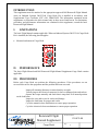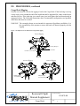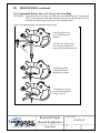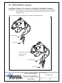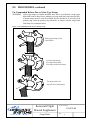
1
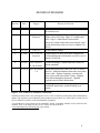
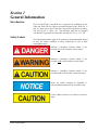
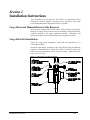
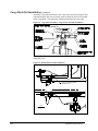
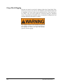
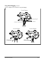
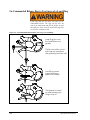
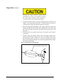
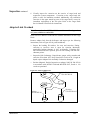
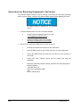
Big Mouth Cargo Hook Kit for the Bell 206 A & B Series Kit Part Number 200-232-00 Owner's Manual Owner's Manual Number 120-074-00 Revision 8 September 14, 2010 13915 NW 3rd Court Vancouver Washington 98685 USA Phone: 360-546-3072 Fax: 360-546-3073 Toll Free: 800-275-0883 www.OnboardSystems.com This page intentionally left blank. RECORD OF REVISIONS Revision Date Page(s) 2 3-9-00 4-8,4-9 3 6-26-00 4 9/17/02 Title, 4-3 5 01/18/07 2-2, 2-3 & 2-4 04/12/07 Added additional location option of connector plug on solenoid cover. 2-1, 2-2, 2-5, & Figure 2-1 changed washer part number and added Section 4 Torque value to AN Nut. Figure 2-2 added torque value. Page 2-2 added Hook location table. Removed overhaul instructions from Section 4 and moved information to the new Service Manual 122002-00. Section 4 6 Reason for Revision TOC, Section 1, 2-4 & Section 3 7 06/16/10 TOC & Sections 1-4 8 09/14/10 4-3 Factory address change. Updated figures to show new knob configuration. Updated maintenance information to refer to service manual 122-002-00. Updated Warnings, Cautions and Notes format to current standards. Added Manual Release Cable (P/N 268-015-00) to parts list. Added installation instructions for manual release cable. Replaced warnings, cautions and notes section with safety labels section. Updated safety labels throughout document. Updated inspection and overhaul information. Added Figure 4.4, added Link Assembly bushing installation instructions, updated bushing wear criteria. Register Your Products for Automatic Notifications Onboard Systems offers a free notification service via fax or email for product alerts and documentation updates. By registering your Onboard Systems products at our website, we will be able to contact you if a service bulletin is issued, or if the documentation is updated. You can choose to receive notices on an immediate, weekly, or monthly schedule via fax, email or both methods. There is no charge for this service. Please visit our website at www.onboardsystems.com/notify.php to get started. ii This page intentionally left blank. CONTENTS Section 1 General Information Introduction, 1-1 Safety Labels, 1-1 Bill of Materials, 1-2 Inspection, 1-2 Specifications, 1-2 Theory of Operation , 1-3 Section 2 Installation Instructions Cargo Hook and Manual Release Cable Removal, 2-1 Cargo Hook Kit Installation, 2-1 Installation Check-Out, 2-6 Component Weights, 2-6 Cargo Hook Location, 2-6 Paper Work, 2-6 Section 3 Operation Instructions Operating Procedures, 3-1 Cargo Hook Rigging, 3-2 Cargo Hook Rigging Illustrations, 3-3 Section 4 Maintenance Storage Instructions, 4-1 Preventive Maintenance, 4-1 Inspection, 4-1 Adapter Link Overhaul, 4-3 Instructions for Returning a System to the Factory, 4-4 iii CONTENTS, continued Section 5 Certification STC, 5-1 STA, 5-3 Rotorcraft Flight Manual Supplement Figures 2-1 2-2 2-3 2-4 2-5 2-6 2-7 3-1 3-2 3-3 3-4 3-5 4-1 Manual Release Cable Installation, 2-1 Link Adapter Assembly Installation, 2-2 Cargo Hook Assembly to Cargo Frame Assembly, 2-2 Manual Release Cable Rig, 2-3 Adel Clamp and Shock Cord Installation, 2-3 Cargo Frame Assembly Overview, 2-4 Un-commanded Release, 2-5 Examples of Correct and Incorrect Cargo Hook Rigging, 3-3 Un-commanded Release Due to Large Load Ring, 3-4 Load Hang-Up, Too Small or Multiple Load Rings, 3-5 Un-Commanded Release Due to Nylon Straps, 3-6 Un-Commanded Release Due to Cable or Rope Straps, 3-7 Link Assembly Parts, 4-2 1-1 2-1 2-2 2-3 Cargo Hook Specifications, 1-1 Cargo Hook Connector, 2-3 Component Weights, 2-5 Cargo Hook Location, 2-5 Tables iv Section 1 General Information Introduction The P/N 200-232-00 Cargo Hook kit is approved for installation on the 206A and 206B. The kit replaces the Breeze-Eastern hooks, SP4232-4, -5 and -5L when used as part of the Bell Cargo Hook Suspension Assembly, P/N 206-706-335-1, -101or -103. The helicopter must also be equipped with the Bell Cargo Hook Provisions Kit, P/N 206-706-335-3, -5 or –105. Safety Labels The following definitions apply to the symbols used throughout this manual to draw the reader’s attention to safety instructions as well as other important messages. Indicates a hazardous situation which, if not avoided, will result in death or serious injury. Indicates a hazardous situation which, if not avoided, could result in death or serious injury. Indicates a hazardous situation which, if not avoided, could result in minor or moderate injury. Draws the reader’s attention to important or unusual information not directly related to safety. Used to address practices not related to personal injury. General Information 1-1 Bill of Materials The following items are included with the Cargo Hook Kit, if shortages are found contact the company from whom the system was purchased. Part Number 120-074-00 122-002-00 210-164-00 268-015-00* 290-426-00 510-252-00 512-010-00 528-017-00 Description Cargo Hook Kit Owner's Manual Big Mouth Hook Service Manual Adapter Link Assembly Manual Release Cable Release Fitting Jam Nut Adel Clamp Cargo Hook Quantity 1 1 1 1 1 1 2 1 * Kits sold after June 16, 2010 include the Manual Release Cable, prior to this the kit utilized the existing OEM release cable. Inspection Inspect the kit items for evidence of damage, corrosion and security of lock wire and fasteners. If damage is evident, do not use the items until they are repaired. Specifications Table 1-1 Cargo Hook Specifications Design load Design ultimate strength Electrical release capacity Mechanical release capacity Force required for mechanical release at 3,500 lb. Electrical requirements Minimum release load Unit weight Mating electrical connector 1-2 3,500 lb. (1,587 kg.) 15,750 lb. (7,144 kg.) 8,750 lb. (3,969 kg.) 8,750 lb. (3,969 kg.) 10 lb. Max. (.600” travel) 22-28 VDC, 9.8–12.5 amps 10 pounds 5.75 pounds (2.6 kg.) PC06A8-2S SR General Information Theory of Operation The primary elements of the Cargo Hook are the load beam, the internal mechanism, and a DC solenoid. The load beam supports the load and is latched through the internal mechanism. The DC solenoid and an external manual release cable provide the means for unlatching the load beam. The load beam is normally returned to its closed position after release of the load by a spring in the internal mechanism. In the closed position, a latch engages the load beam and latches it in this position. The load is attached to the load beam by passing the cargo sling ring into the throat of the load beam past a spring-loaded keeper, which secures the load. To release the load, the latch is disengaged from the load beam. With the latch disengaged, the weight of the load causes the load beam to swing to its open position, and the cargo sling slides off the load beam. A spring in the internal mechanism then drives the load beam back to its closed and latched position. A load release can be initiated by three different methods. Normal release is achieved by pilot actuation of the push-button switch in the cockpit. When the push-button switch is pressed, it energizes the DC solenoid in the Cargo Hook, and the solenoid opens the latch in the internal mechanism. In an emergency, release can be achieved by operating a mechanical release cable. The manual release cable operates the internal mechanism of the Cargo Hook to unlatch the load beam. The load can also be released by the actuation of a knob located on the side of the Cargo Hook. General Information 1-3 This page intentionally left blank. Section 2 Installation Instructions These procedures are provided for the benefit of experienced aircraft maintenance facilities capable of carrying out the procedures. They must not be attempted by those lacking the necessary expertise. Cargo Hook and Manual Release Cable Removal Disconnect the manual and electrical release cables from the Cargo Hook. Remove the Cargo Hook from the universal assembly leaving the universal assembly attached to the cargo suspension assembly. Disconnect and remove the manual release cable from the cargo suspension assembly Cargo Hook Kit Installation Inspect the cargo frame assembly to insure that all components are in serviceable condition. Attach the link adapter assembly to the Cargo Hook using the hardware supplied, as illustrated below. Torque AN nut 510-170-00 to 50 in-lbs, then rotate nut to next castellation, not to exceed 110 in-lbs. Install and secure cotter pin 510-178-00. Figure 2-1 Link Adapter Assembly Installation Installation Instructions 2-1 Cargo Hook Kit Installation, continued Attach the Cargo Hook assembly to the cargo frame assembly using the Bell supplied hardware that was previously used to attach the universal assembly to the Cargo Hook. The cargo hook load beam should point to the right. Figure 2-2 Cargo Hook Assembly to Cargo Frame Assembly Installation Attach the manual release cable to the cargo suspension assembly, as illustrated below. Figure 2-3 Manual Release Cable Installation MANUAL RELEASE CABLE P/N 268-015-00 LOAD LIMIT 1500 LB FWD 2-2 Installation Instructions Cargo Hook Installation, continued Thread the release fitting (P/N 290-426-00) into the cargo hook. Remove the cargo hook manual release cover and connect the manual release cable. Place the cable ball end fitting into the hook manual release fork fitting as illustrated in Figure 2-4. Check that there is a minimum of .125” of free play at the fork fitting as shown in Figure 2-4. Figure 2-4 Manual Release Cable Rig MANUAL RELEASE KNOB SAFETY WIRE MANUAL RELEASE CABLE ADAPTER JAM NUT FORK FITTING BALL END FITTING .125 FREE PLAY Attach the supplied adel clamps through the end loops of the cargo hook restraining shock cord. Route the shock cord through the eyelet and over the threaded rod as illustrated in Figures 2-4 and 2-5. Secure the adel clamps to the screws on the cargo hook manual release cover as illustrated and safety wire. Figure 2-5 Adel Clamp and Shock Cord Installation ADEL CLAMP SHOCK CORD MANUAL RELEASE KNOB SIDE OF HOOK Installation Instructions 2-3 Cargo Hook Installation, continued Figure 2-6 Cargo Frame Assembly Overview Cargo Frame Assembly Eyelet Universal Assembly Threaded Rod Link Adapter Assembly Hook Retracted Shock Cord Cargo Hook in Extended Postion Connect the cargo hook electrical release cable connector to the Cargo Hook. Listed below is the pin out for the cargo hook connector. Table 2-1 Cargo Hook Connector 2-4 Pin Function A Ground B Power Installation Instructions Cargo Hook Installation, continued Un-commanded cargo hook release will happen if the manual and electrical release cables are improperly restrained. The cables must not be the stops that prevent the Cargo Hook from swinging freely in all directions. If the Cargo Hook loads cause the hook to strain against the manual release cable the swaged end of the cable may separate allowing the inner cable to activate the cargo hook manual release mechanism. The result is an un-commanded release. Ensure that no combination of cyclic stick or Cargo Hook position is restrained by the manual or electrical release cables. Figure 2-7 Un-commanded Release From Incorrectly Secured Cable HOOK ROTATES AND STRAINS AGAINST THE MANUAL RELEASE CONDUIT THE STRAIN ON THE CONDUIT EXCEEDS THE PULL-OFF FORCE BETWEEN THE SWAGED FITTING AND THE CONDUIT THE SWAGED JOINT FAILS AND ALLOWS THE INNER CABLE TO ACTIVATE THE HOOK'S MECHANICAL RELEASE MECHANISM AND THE HOOK OPENS THE LOAD RING FALLS FREE IN AN UN-COMMANDED RELEASE Installation Instructions 2-5 Installation Check-Out After installation of the Cargo Hook, perform the following functional checks. 1. Swing the installed Cargo Hook to ensure that the manual release cable assembly and the electrical release cable have enough slack to allow full swing of the suspension assembly without straining or damaging the cables. The cables must not be the stops that prevent the Cargo Hook from swinging freely in all directions. 2. Apply 10-20 pounds to the cargo hook load beam and pull the handle operated cargo hook mechanical release, the Cargo Hook should release. 3. Close the cargo hook release circuit breaker and position the battery switch to the ON position. Apply 10-20 pounds to the cargo hook load beam and depress the cargo hook electrical release button, the Cargo Hook should release. 4. See the Bell Helicopter service instructions for your specific helicopter model for additional installation instructions. Component Weights The weight of the cargo hook components are listed in Table 2-2. Table 2-2 Component Weights Item Cargo Hook Weight lbs (kgs) 5.75 (2.61) Link Adapter assembly 1.0 (.45) Manual Release Cable .25 (.11) Cargo Hook Location Table 2-3 Cargo Hook Location Fuselage Station 108.5 Paper Work Remove the Flight Manual Supplement from the back of this manual and place it into the Rotorcraft Flight Manual. In the US, fill in FAA form 337 for the initial installation. This procedure may vary in different countries. Make the appropriate aircraft log book entry. 2-6 Installation Instructions Section 3 Operation Instructions Operating Procedures Prior to each job perform the following: 1. Ensure that the Cargo Hook has been properly installed and that the manual and electrical release cables do not limit the movement of the hook. 2. Be completely familiar with this manual, particularly the Cargo Hook rigging section. 3. Be completely familiar with all Bell Helicopter Cargo Hook operating instructions. 4. Activate the electrical system and press the release button to ensure the cargo hook electrical release is operating correctly. The Cargo Hook must relatch after release. If the hook does not relatch do not use the unit until the difficulty is resolved. The cargo hook release solenoid is intended to be energized only intermittently. Depressing the electrical release button continuously in excess of 20 seconds will cause the solenoid to overheat, possibly causing permanent damage. 5. Activate the manual release knob to test the cargo hook manual release mechanism. The mechanism should operate smoothly and the Cargo Hook must relatch after release. If the hook does not relatch do not use the unit until the difficulty is resolved. See the trouble shooting table in Section 4 and the Bell service instructions that cover the original Cargo Hook installation for additional instructions. Operation Instructions 3-1 Cargo Hook Rigging Extreme care must be exercised in rigging a load to the Cargo Hook. If the load ring is too big it may work its way around the end of the load beam and be supported for a time on the keeper and then fall free. If the load ring is too small it may jam itself against the load beam during an attempted release. The following illustrations show recommended configurations and potential difficulties that must be avoided. The examples shown are not intended to represent all problem possibilities. It is the responsibility of the operator to assure the hook will function properly with the rigging. 3-2 Operation Instructions Cargo Hook Rigging, continued Figure 3-1 Examples of Correct and Incorrect Cargo Hook Rigging Correct Rigging Keeper Load Beam 1.50" Primary Ring I.D. 2.25" Primary Ring Secondary Ring or Shackle 1/2" Max. Cross Section Load Incorrect Rigging Incorrect Rigging Keeper Multiple Rings on Load Beam. Operation Instructions Load Beam Keeper Load Beam Multiple Rings on Primary Ring 3-3 Un-Commanded Release Due to Too Large of a Load Ring Load rings that are too large will cause an uncommanded release. The ring will flip over the end of the load beam and flip the keeper up and then fall free. Only correctly sized load rings must be used. See examples below. Figure 3-2 Un-Commanded Release Due to Too Large of a Load Ring Keeper Load Beam Load Ring flips over the Load Beam and gyrates. The flip over often occurs with long line operations during landing and take offs Load Ring moves inward and bears against the keeper The Keeper is forced to rotate allowing the Ring to slip off 3-4 Operation Instructions Load Hang-Up Due to Too Small of a Load Ring or Multiple Load Rings Load rings that are too small or multiple load rings will hang on the load beam when the load is released. Only correctly sized load rings must be used. See examples below. Figure 3-3 Load Hang-Up Due to Too Small a Load Ring or Multiple Load Rings Jammed Ring Sling Load Load hang-up due to multiple rings on load beam Jammed Rings Sling Load Operation Instructions 3-5 Un-Commanded Release Due to Nylon Type Straps Nylon type straps (or similar material) must not be used directly on the cargo hook load beam as they have a tendency to creep under the keeper and fall free. If nylon straps must be used they should be first attached to a correctly sized primary ring. Only the primary ring should be in contact with the cargo hook load beam. See examples below. Figure 3-4 Un-Commanded Release Due to Nylon Type Straps Nylon type strap on the Load Beam As the load swings the strap fibers work their way under the keeper The strap works its way off of the load beam 3-6 Operation Instructions Un-Commanded Release Due to Cable or Rope Type Straps Cable or rope type straps must not be used directly on the cargo hook load beam. Their braided eyes will work around the end of the load beam and fall free. If cable or rope is used they should be first attached to a correctly sized primary ring. Only the primary ring should be in contact with the cargo hook load beam. See examples below. Figure 3-5 Un-Commanded Release Due to Cable or Rope Type Straps Cable or rope type line flips over the Load Beam The flip over oftens occurs with long line operations during landings and take offs Load Ring moves inward and bears against the keeper The keeper rotates allowing the Ring to slip off Cargo Hook Suspension System Operation Instructions 3-7 This page intentionally left blank. Section 4 Maintenance Storage Instructions Clean the Cargo Hook thoroughly before packaging. Pack the unit in a heatsealable package. If the unit is to be stored for long periods in a tropical climate it should be packed in a reliable manner to suit local conditions. Refer to relevant MIL specifications. After the Cargo Hook has been repaired or stored for an extended period of time it must be subjected to the Acceptance Test Procedure per service manual 122-002-00. Package the unit in a suitable fiberboard box and cushion the unit to prevent shifting. Seal the fiberboard box with tape and mark the box with the contents and date of packaging. Preventive Maintenance Remove caked-on dirt from the Cargo Hook with a brush and clean exposed surfaces with a mild solvent. Thoroughly dry all surfaces. Inspection The scheduled inspection intervals noted below are maximums and are not to be exceeded. If the cargo hook is subjected to unusual circumstances, extreme environmental conditions, etc., it is the responsibility of the operator to perform the inspections more frequently to ensure proper operation. Annually or 100 hours of external load operations, whichever comes first, inspect the cargo hook kit per the following. Hours of external load operations is defined as the time in which a helicopter is engaged in external load operations. This includes time between loads on the hook. 1. Activate the helicopter electrical system and press the cargo release button to ensure the cargo hook electrical release is operating correctly. The cargo hook must release. If the hook does not release or re-latch, do not use the unit until the problem is corrected. Maintenance 4-1 Inspection continued Pressing the cargo electrical release button continuously in excess of 20 seconds will cause the cargo hook electrical release solenoid to overheat, possibly causing permanent damage. 2. Activate the manual release system by pulling the release handle in the cockpit. The cargo hook must release. If the hook does not release or re-latch, do not use the unit until the problem is corrected. 3. Move the cargo hook throughout its full range of motion to ensure the manual and electrical release cables have enough slack. The cables must not be the stops that prevent the cargo hook from moving freely in all directions. 4. Visually check for presence and security of fasteners and electrical connections. 5. Visually inspect the manual release cable for damage, paying close attention to the flexible conduit at the area of transition to the cargo hook end fitting (refer to Figure 4-1). Inspect for splitting of the outer black conduit and heat shrink in this area and separation of the conduit from the steel end fitting. Figure 4-1 Manual Release Cable Inspection Pay close attention to this area of the manual release cable. . 4-2 Maintenance Inspection continued 6. Visually inspect for corrosion on the exterior of cargo hook and suspension system components. Corrosion on the cargo hook side plates is cause for immediate overhaul. Additionally, any exfoliation corrosion in the upper attach lug area of the cargo hook is cause for immediate replacement of the side plate. Refer to the Cargo Hook Service Manual 122-002-00 for instructions Adapter Link Overhaul Time Between Overhaul (TBO): 1000 hours of external load operations or 5 years, whichever comes first. Refer to Service Manual 122-002-00 for overhaul information for the Cargo Hook. Remove adapter link from the helicopter and inspect per the following instructions (refer to Figure 4-2 for parts breakdown). o Inspect the bushing ID surfaces for wear and corrosion. Pitting, corrosion or excessive wear is cause for rejection. Maximum permissible bushing clearance is .010” on diameter. If bushing P/N 290-364-00 needs to be replaced, press in new bushing with wet zinc chromate primer. o Inspect the link for damage. Repair dents, gouges, nicks, scratches and corrosion if less than .030” deep, blend out at a ratio of 20:1, length to depth, replace Adapter Link Assembly if otherwise damaged. o Perform Magnetic Particle Inspection on adapter link P/N 290-363-00 in accordance with ASTM E-1444 and MIL-STD-1907, Grade A. No cracks are permitted. Figure 4-2 Link Assembly Parts Link Adapter P/N 290-363-00 Bushing P/N 290-365-00 Maintenance Bushing P/N 290-364-00 4-3 Instructions for Returning Equipment to the Factory If an Onboard Systems product must be returned to the factory for any reason (including returns, service, repairs, overhaul, etc) obtain an RMA number before shipping your return. An RMA number is required for all equipment returns. To obtain an RMA, please use one of the listed methods. Contact Technical Support by phone or e-mail ([email protected]). Generate an RMA number at our website: http://www.onboardsystems.com/rma.php After you have obtained the RMA number, please be sure to: Package the component carefully to ensure safe transit. Write the RMA number on the outside of the box or on the mailing label. Include the RMA number and reason for the return on your purchase or work order. Include your name, address, phone and fax number and email (as applicable). Return the components freight, cartage, insurance and customs prepaid to: Onboard Systems 13915 NW 3rd Court Vancouver, Washington 98685 USA Phone: 360-546-3072 4-4 Maintenance Section 5 Certification STC Certification 5-1 5-2 Certification STA Certification 5-3 This page intentionally left blank. FAA APPROVED ROTORCRAFT FLIGHT MANUAL SUPPLEMENT Bell Helicopter Models 206A & 206B R/N ____________________ S/N ____________________ Rotorcraft Flight Manual Supplement Cargo Hook Document Number 120-074-00 Page 1 INTRODUCTION This supplement must be attached to the appropriate approved Bell Rotorcraft Flight Manual when an Onboard Systems 200-232-00 Cargo Hook Kit is installed in accordance with Supplemental Type Certificate (STC) NO. SR00538SE. The information contained herein supplements or supersedes the basic manual only in those areas listed herein. For limitations, procedures and performance information not contained in this supplement, consult the basic Rotorcraft Flight Manual. I. LIMITATIONS The basic Flight Manual remains applicable. When an Onboard Systems 200-232-00 Cargo Hook Kit is installed, the following placard applies: II. Mounted on bottom of Cargo Hook. PERFORMANCE The basic Flight Manual and Bell Rotorcraft Flight Manual Supplement-Cargo Hook remains applicable. III. PROCEDURES Before each Cargo Hook use perform the following procedures. If the procedures are not successful do not use the equipment until the problem has been corrected. Inspect all mounting fasteners to ensure that they are tight. Visually inspect the electrical connector for loose or damaged pins and sockets. Operate the keeper manually and check that it snaps back to its normal position on the load beam. Inspect the case and covers for cracks and damage. Inspect the load beam for gouges and cracks. Cycle the manual release mechanisms to ensure proper operation. Cycle the electrical release mechanisms to ensure proper operation. Rotorcraft Flight Manual Supplement Cargo Hook Document Number 120-074-00 Page 2 III. PROCEDURES, continued Cargo Hook Rigging Extreme care must be exercised in rigging a load to the Cargo Hook. If the load ring is too big it may work its way around the end of the load beam and be supported for a time on the keeper and then fall free. If the load ring is too small it may jam itself against the load beam during an attempted release. The following illustrations show recommended configurations and potential difficulties that must be avoided. WARNING: The examples shown are not intended to represent all problem possibilities. It is the responsibility of the operator to assure the hook will function properly with the rigging. Figure 1 Examples of correct and incorrect cargo hook rigging Correct Rigging Keeper Load Beam 1.50" Primary Ring I.D. 2.25" Primary Ring Secondary Ring or Shackle 1/2" Max. Cross Section Load Incorrect Rigging Incorrect Rigging Keeper Multiple Rings on Load Beam. Load Beam Keeper Load Beam Multiple Rings on Primary Ring Rotorcraft Flight Manual Supplement Cargo Hook Document Number 120-074-00 Page 3 III. PROCEDURES, continued Un-Commanded Release Due to Too Large of a Load Ring WARNING: Load rings that are too large will cause an un-commanded release. The ring will flip over the end of the load beam and flip the keeper up and then fall free. Only correctly sized load rings must be used. See examples below. Figure 2 Un-commanded release due to load rings that are too large Keeper Load Beam Load Ring flips over the Load Beam and gyrates. The flip over often occurs with long line operations during landing and take offs Load Ring moves inward and bears against the keeper The Keeper is forced to rotate allowing the Ring to slip off Rotorcraft Flight Manual Supplement Cargo Hook Document Number 120-074-00 Page 4 III. PROCEDURES, continued Load Hang-Up Due to Too Small of a Load Ring or Multiple Load Rings WARNING: Load rings that are too small or multiple load rings will hang on the load beam when the load is released. Only correctly sized load rings must be used. See examples below. Figure 3 Load hang-up due to load rings that are too small or using multiple load rings Jammed Ring Sling Load Load hang-up due to multiple rings on load beam Jammed Rings Sling Load Rotorcraft Flight Manual Supplement Cargo Hook Document Number 120-074-00 Page 5 III. PROCEDURES, continued Un-Commanded Release Due to Nylon Type Straps WARNING: Nylon type straps (or similar material) must not be used directly on the cargo hook load beam as they have a tendency to creep under the keeper and fall free. If nylon straps must be used they should first be attached to a correctly sized primary ring. Only the primary ring should be in contact with the cargo hook load beam. See examples below. Figure 4 Un-commanded release due to nylon type straps Nylon type strap on the Load Beam As the load swings the strap fibers work their way under the keeper The strap works its way off of the load beam Rotorcraft Flight Manual Supplement Cargo Hook Document Number 120-074-00 Page 6 III. PROCEDURES, continued Un-Commanded Release Due to Cable or Rope Type Straps WARNING: Cable or rope type straps must not be used directly on the cargo hook load beam. Their braided eyes will work around the end of the load beam and fall free. If cable or rope is used they should first be attached to a correctly sized primary ring. Only the primary ring should be in contact with the cargo hook load beam. See examples below. Figure 5 Un-commanded release due to cable or rope type straps Cable or rope type line flips over the Load Beam The flip over oftens occurs with long line operations during landings and take offs Load Ring moves inward and bears against the keeper The keeper rotates allowing the Ring to slip off Rotorcraft Flight Manual Supplement Cargo Hook Document Number 120-074-00 Page 7