1
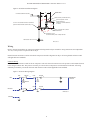
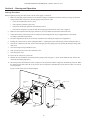
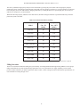
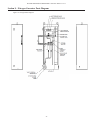
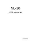
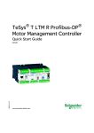
Potter Nitrogen Generator
Installation, Operation, & Service Manual
CORROSION
SOLUTIONS
Potter Electric Signal Company, LLC
St. Louis, MO
Customer Service: (866) 240-1870 • Technical Support: (866) 956-1211 • Fax: (314) 595-6999
www.pottersignal.com
Manual #5403585–Rev. D
08/11
Potter nitrogen generator • 5403585 • REV D • 8/11
2
Potter nitrogen generator • 5403585 • REV D • 8/11
Table of Contents
Safety................................................................................................................................................................................. 4
Safety Guidelines........................................................................................................................................................... 4
Important Notice to Users.............................................................................................................................................. 4
Unpacking...................................................................................................................................................................... 4
System Description........................................................................................................................................................... 6
Installation Instructions.................................................................................................................................................. 8
Initial Inspection (Arrival)............................................................................................................................................. 8
Receiving....................................................................................................................................................................... 8
Rigging & Moving......................................................................................................................................................... 8
Location & Installation.................................................................................................................................................. 8
Air Compressor Package (Except NGP-220).............................................................................................................. 8
Nitrogen Generator..................................................................................................................................................... 9
Nitrogen Storage Tank................................................................................................................................................. 9
Refrigerated Air Dryer (Separate, for NGP-3100 ONLY).......................................................................................... 9
NGP-SPV Self-Purging Valve Kit................................................................................................................................ 9
NGP-220...................................................................................................................................................................... 9
Installation .................................................................................................................................................................. 10
Wiring...........................................................................................................................................................................11
NGP-220 Wiring.........................................................................................................................................................11
Start-up and Operation................................................................................................................................................. 12
Start-up Procedure....................................................................................................................................................... 12
Filling Procedure.......................................................................................................................................................... 13
Filling Procedure 1: Air Filling Method................................................................................................................... 14
Normal Operation........................................................................................................................................................ 15
Maintenance................................................................................................................................................................... 16
Filter Replacement....................................................................................................................................................... 17
NGP-220 Filter Replacement.................................................................................................................................... 17
Automatic Drain Cleaning........................................................................................................................................... 17
Desiccant Dryer Maintenance...................................................................................................................................... 18
Nitrogen Analyzer Instructions..................................................................................................................................... 19
Automatic Calibration.................................................................................................................................................. 19
Calibrating the N2 Analyzer......................................................................................................................................... 19
Calibration Errors and Error Codes............................................................................................................................. 19
Changing the Batteries................................................................................................................................................. 20
Changing the Oxygen Sensor....................................................................................................................................... 20
Troubleshooting.............................................................................................................................................................. 22
Nitrogen Generator Parts Diagram.............................................................................................................................. 23
Technical Specifications and Drawings........................................................................................................................ 24
Technical Diagrams and Illustrations.......................................................................................................................... 25
Factory Settings.............................................................................................................................................................. 33
Maintenance and Purge Log......................................................................................................................................... 34
Warranty Policy............................................................................................................................................................. 35
3
Potter nitrogen generator • 5403585 • REV D • 8/11
Section 1 – Safety
Safety Guidelines
This manual contains safety information that is important to know and understand. This information is provided for for the safety
of installers, operators, and users of the Potter Nitrogen Generator as well as equipment. To help recognize this information,
observe the following symbols.
D
Danger indicates an imminently hazardous situation which, if not avoided, WILL result in death or serious injury.
Warning indicates a potentially hazardous situation which, if not avoided COULD result in death or serious injury.
Caution indicates a potentially hazardous situation which, if not avoided, MAY result in minor or moderate injury.
Notice indicates important information, that if not followed may cause damage to equipment or property.
Important Notice to Users
The Installation and Owner’s Manual supplied with each unit must be read thoroughly and completely understood before
installation and operation of the Potter Nitrogen Generator. All appropriate safety standards for handling of gases as determined
by local or national laws and regulations should be followed at all times.
Unpacking
After unpacking unit, carefully inspect all parts and equipment for any damage that may have occurred during transit. Make sure
to tighten fittings, bolts, etc., before putting unit into service.
Do not operate unit if damaged occured during shipping, handling,
or use. Contact Potter immediately.
General Safety Information
Important: Read all of the safety information in this manual before operating this equipment. Use of the equipment in a manner
not specified within this manual may impair the protection provided by the generator and could result in an unplanned release of
pressure, which may cause serious injury or damage. Only competent personnel, who have been trained, qualified, and approved
by Potter Electric Signal Company should perform commissioning, servicing, and repair procedures.
When handling, installing, or operating this equipment, personnel must employ safe engineering practices and observe all related
local regulations, health, and safety procedures, and legal requirements for safety.
Ensure that the equipment is depressurized and electrically isolated, before carrying out any of the scheduled maintenance
instructions specified in this manual.
The warnings in this manual cover the most known potential hazards, but by definition cannot be all-inclusive. If the user employs
an operating procedure, item of equipment, or a method of working that is not specifically recommended by Potter Electric Signal
Company, the user must ensure that the equipment will not be damaged or become hazardous to persons or property.
4
Potter nitrogen generator • 5403585 • REV D • 8/11
Nitrogen is not a poisonous gas. However, in a concentrated form, there is a risk of asphyxiation. The generator produces a flow
of nitrogen and oxygen enriched air which quickly disperses in the atmosphere. However, do not directly inhale the output gas
from the outlet pipe.
The generator is classified as non-hazardous for transportation purposes and as non-flammable for fire regulations. This equipment
is for indoor use only. Do not operate outdoors.
Operation of the nitrogen membrane separator above the rated
design pressure may be hazardous. Do not connect it to
compressed air sources that can exceed its maximum rated
pressure without installing appropriate pressure controls and
safety relief devices in the compressed air supply line.
Specific procedures must be developed for maintenance of the equipment on which the membrane separator is located.
Appropriate labels must be continuously displayed in all areas where personnel might be exposed to a nitrogen atmosphere
under normal or upset conditions.
Do not attempt to disassemble the nitrogen membrane separator.
Equipment damage may occur and cause the system to function
incorrectly.
5
Potter nitrogen generator • 5403585 • REV D • 8/11
Section 2 – System Description
The Potter Nitrogen Generator operates using membrane technology. The smaller oxygen and water vapor molecules can pass
through (permeate) the membrane quickly. The larger nitrogen molecules are less likely to diffuse through the separator tubes;
therefore, they continue downstream to the separator outlet. The permeate molecules are discharged to atmosphere through a vent
in the separator casing.
The Potter Nitrogen Generator is specifically designed to provide clean, dry, pure nitrogen for use in fire protection sprinkler
systems. The generator is a fully assembled package ready to be connected to a new or existing fire sprinkler system using either
a factory pre-engineered air compressor or an existing air source capable of providing the required air flow and air quality for the
installation. These turn-key systems include all air filtration required to keep the generator operating at peak efficiency, and most
models come standard with pressure gauges and a nitrogen purity analyzer (except NGP-220).
Figure 1. Typical Complete System Diagram
Figure 2. Typical N2 Generator Unit Diagram
Nitrogen generation is affected by four (4) variables – Temperature, Flow Rate, Membrane Pressure, and Vent Pressure.
6
Potter nitrogen generator • 5403585 • REV D • 8/11
Figure 3. NGP-220 Unit Diagram
PRESSURE
GAUGE
PG
CHECK
VALVE
FLOW
CONTROL
VALVE
BLOCKING
VALVE
METERING
VALVE
ANALYZER
CONNECTION
PRESSURE
RELIEVING VALVE
ANALYZER
OIL LESS COMPRESSOR
BLOCKING
VALVE
AFTER COOLER
PS-2
PRESSURE
SWITCH
#6
COALESCING
#6
FILTER
COALESCING
FILTER
MANUAL
DESICCANT
DRYER
BYPASS
VALVE
PRESSURE
SWITCH
ORIFICE CHECK
VALVE
PS-1
SAFETY RELIEF
VALVE
TO SYSTEM
AMD-1
DWG. # 585-1
NITROGEN RECEIVER
7
Potter nitrogen generator • 5403585 • REV D • 8/11
Section 3 – Installation Instructions
Initial Inspection (Arrival)
Check all packages andcrates in shipment for damage. If damage is found, contact the carrier immediately and file a shipping
damage claim with the carrier.
Make sure that all ordered parts were received. If there are any missing parts, call the shipping carrier immediately.
If there are any questions concerning the shipment, contact Potter Electric Signal at 800-325-3936.
Receiving
The compressor is inspected at the factory and packaged to protect against shipping damage. When the Potter Nitrogen Generator
is unpacked, inspect for damage or missing parts. Contact the shipping carrier to settle all claims.
Do not operate the Potter Nitrogen Generator if damaged
during shipment, handling, or use. Damage may result in
bursting and cause injury or property damage.
Rigging & Moving
Only move the supplied equipment with the correct material handling equipment. Always follow safety guidelines when moving the
equipment. Make sure they are secured correctly before moving.
Location & Installation
There are up to 4 items to be installed with each Potter Nitrogen Generator system (depending on model). Determine the best
location for each item and install each as shown on the system layout diagram.
Figure 4. Typical System Layout
AIR MAINTENANCE
DEVICE
REFRIGERATED
DRYER
TO R
IS
ER
NITROGEN
STORAGE TANK
ELECTRICAL
PANEL
COMPRESSOR
NITROGEN GENERATOR
CABINET
DWG. #0400-2
Air Compressor Package (Except NGP-220)
Install the air compressor package on a level surface close to the nitrogen generator and nitrogen storage tank. The air compressor
package includes a dryer. The exact location to the nitrogen generator and nitrogen storage tank isn’t critical; however, electrical
power is required for the air compressor package and could be a factor in determining the ideal location. A dedicated 115 volt,
15 amp electrical circuit is required for the air dryer. The air compressor package should be permanently installed following the
General Air Products air compressor manual (provided).
8
Potter nitrogen generator • 5403585 • REV D • 8/11
Do not install the AIR COMPRESSOR PACKAGE in an area where ammonia, sulfur dioxide, hydrogen sulfide, mercaptans,
chlorides, chlorine, oxides of nitrogen, acid fumes, solvent vapors, and ozone vapors or similar contaminants exist. The
equipment can be damaged by ammonia and other vapors, shortening membrane life. Locate the air compressor package to
make sure no vapors are drawn into the intake. Avoid locations such as a loading dock, where large amounts of exhaust fumes
and smoke may enter the air intake.
Nitrogen Generator
Install the Potter Nitrogen Generator in a clean, dry location, with ambient temperatures above 50° F at all times. The generator
unit should be leveled and anchored to the floor or wall with appropriate fasteners. If the location is below freezing at any time the
generator unit must be enclosed in a separate, heated enclosure to keep the temperature above 50° F. The nitrogen generator must
be accessible at the front for servicing all major components inside the cabinet.
Unless factory authorized, no more than five (5) riser systems are to be connected to a single Potter Nitrogen Generator .
Exceeding the fill capacities can result in compressor run times that can shorten the compressor life.
Nitrogen Storage Tank
Bolt tank firmly to a level surface in a convenient location close to the fire sprinkler system connections. Support the piping to and
from the tank independently.
Refrigerated Air Dryer (Separate, for NGP-3100 ONLY)
Install the refrigerated air dryer assembly on a level surface close to the air compressor assembly and nitrogen generator. The
intake port of the air dryer should be below the exhaust port of the air compressor after-cooler. Do not over elevate the dryer. The
distance between the air dryer and the air compressor isn’t critical; however, a dedicated 115 volt, 15 amp electrical circuit is
required for the air dryer. The air dryer should be permanently installed to the floor using appropriate fasteners.
NGP-SPV Self-Purging Valve Kit
Install a purge valve assembly kit on each system in a tee prior to the inspector test valve to aid in removal of oxygen during the
purge process. The purge valve maintains system pressure during the purge process and prevents a system trip due to pressure
loss. The air vent in the NGP-SPV automatically closes if water reaches the vent in the event of a alarm condition.
A plug is supplied to keep purge orifice free of debris when not in use. A ball valve allows isolation of assembly when not surging,
to allow maintenance of strainer screen, replacement of air vent, or maintenance of purge orifice in the event it becomes clogged.
NGP-220
The NGP-220 includes a nitrogen storage tank, oil-less air compressor. Nitrogen generator all mounted as one unit.
Install the NGP-220 by bolting the tank firmly to a level surface in a convenient location close to the fire sprinkler system
connections. Support the pipe to and from the tank independently.
9
Potter nitrogen generator • 5403585 • REV D • 8/11
Installation
Use back-up wrenches when making connections or piping damage may occur.
All piping connections must be independently supported and not impart stress on the components.
1. For models NGP-415, 750, 1150, 2500, and 2500H: install piping from the air compressor package air outlet to the
nitrogen generator air inlet.
For model NGP-3100: install piping from the air dryer outlet to the nitrogen generator air inlet. Use ½” NPT pipe or
larger. If the compressor package was not ordered with the Potter Nitrogen Generator, connect the nitrogen generator
inlet air connection to a source of compressed air. The air should be a minimum of 40° F pressure dew point, and should
be free of liquid oil and water (see specification chart).
For Model NGP-220: follow steps 5, 6, and 8 ONLY.
2. Install piping (½” minimum pipe) from the nitrogen generator outlet to the nitrogen storage tank
3. Install piping from refrigerated air dryer and nitrogen generator condensate outlet connections to an appropriate drain
location. Follow local regulations when disposing of condensate. (Some local regulations may require an oil/water
separator.)
Pipe the discharged air and water to a position where the it
will not be a hazard to personnel.
4. Install ¼” copper tubing (or equivalent) from the PS-2 pressure switch compression fitting located on the air compressor
assembly to the nitrogen storage tank ¼” compression fitting. (Does not apply to NGP-220 & NGP-750 SOLO model.)
5. Install ½” NPT pipe (or larger) from the nitrogen storage tank outlet connection to the sprinkler system air maintenance
device using standard accepted installation practices. Use ½” NPT pipe or larger.
6. Install ½” NPT pipe (or larger) from the air maintenance device to the sprinkler system using standard accepted
installation practices. Additional system components may be required.
7. Install piping to membrane permeate outlet if required by local jurisdiction, due to inadequate ventilation.
Adequate or outdoor ventilation, may be required by local jurisdiction.
Figure 5. Typical System Layout
REFRIGERATED
DRYER
TO RISER *
AIR MAINTENANCE
DEVICE
DWG. #0400-3
NITROGEN GENERATOR
CABINET
NITROGEN STORAGE
TANK
ELECTRICAL
PANEL
8. Install a NGP-SPV on each riser in a tee prior to the inspector test valve. The purge valve assembly requires a male ½
NPT connection at installed tee. After installation, close ball valve prior to initiating test or purging process. The ball
valve should only be opened when purging the system. A ½” plug is installed in the orifice which requires removal
during purge process. Plug should be installed in orifice when purging process is not being performed to keep orifice free
of debris and buildup.
10
Potter nitrogen generator • 5403585 • REV D • 8/11
Figure 6. NGP-SPV Installation Diagram
NGP-SPV
11"
PIPE FROM SPRINKLER SYSTEM
7"
PURGE ORIFICE (N2 SAMPLING PORT)
1/2" NPT F TEE CONNECTION AND CLOSE NIPPLE
(SUPPLIED BY SPRINKLER CONTRACTOR)
7.3"
PIPE PLUG (INSTALL AFTER
PURGE COMPLETE)
REMOVE PLUG WHEN SAMPLING
N2 LEVELS
UNION - POSITION VENT / ORIFCE
APPROPRIATELY
PURGE BALL VALVE
SHOWN IN NORMAL (NON - PURGE) POSITION
INSPECTOR'S TEST VALVE
DWG. #0400-13
Wiring
Refer to General Air Products air compressor manual and refrigerated air dryer manual for wiring instructions. An independent
115 volt, 15 amp circuit is required for the air dryer.
Install electrical disconnect switches for both the compressor and the refrigerated air dryer. All wiring should conform to NEC
and applicable local standards.
NGP-220 Wiring
Install electrical disconnect switch for the air compressor. The sole electrical connection is to the pressure switch mounted closest
to the nitrogen cabinet door. This pressure switch is pre-wired to the second pressure switch mounted on the tank. All wiring
should be performed by a licensed electrician and conform to NEC and all applicable local standards.
Figure 7. NGP-220 Wiring Diagram
LINE
MOTOR
LINE
5
LINE
7
LINE
PS-2
MOTOR
6
M
COMPRESSOR
MOTOR
PS-1
TANK
PS-2
COMPRESSOR
PIPING
NEUTRAL
MOTOR
LINE
MOTOR
8
PS-1
DWG. #585-2
GROUND
11
Potter nitrogen generator • 5403585 • REV D • 8/11
Section 4 – Start-up and Operation
Start-up Procedure
Before beginning start-up procedure, make sure the water supply is turned off.
1. Make sure all piping connections have been made according to installation instructions. Before powering up the Potter
Nitrogen Generation compressor, check all piping connections for leaks:
• Close all air maintenance device valves.
• Fully open the generator bypass valve.
• Fully close the nitrogen generator inlet and outlet valves.
• Power the air compressor system ON and check all piping connections for leaks, refer to Figure 6.
2. Make sure the compressor has the proper amount of oil (except NGP-220. DO NOT oil the NGP-220).
3. Check that electrical connections to the air compressor and refrigerated air dryer (if applicable) have been made
according to installation instructions.
4. Turn the refrigerated air dryer ON for at least 2 minutes before starting the compressor (if applicable).
5. If filling the system with air, follow Filling Procedure 1. If filling the system with nitrogen, follow Filling Procedure 2.
6. Turn the air compressor OFF and vent the entire nitrogen generator piping system by opening the nitrogen storage tank
drain valve.
7. Close the nitrogen storage tank drain valve.
8. Fully open the generator inlet valve and outlet valve.
9. Close the bypass valve.
10. Power the air compressor system ON.
11. Monitor the inlet, membrane, and outlet pressure gauges. Refer to Figure 6. (Note: for the NGP-220 unit, monitor the
membrane and outlet gauge only.)
12. The outlet pressure builds until it reaches compressor cut-off pressure and the compressor automatically turns off. When
the outlet pressure falls below the cut-in pressure, the air compressors automatically turn on. Refer to Table 1 for Cut-in/
Cut-out pressures.
Figure 8. Leak Check Valve Location Diagram
CHECK
FOR LEAKS
AIR MAINTENANCE
DEVICE
REFRIGERATED
DRYER
CLOSE ALL VALVES
OPEN GENERATOR
BYPASS VALVE
CHECK
FOR LEAKS
CLOSE NITROGEN
INLET/OUTLET VALVES
NITROGEN
STORAGE TANK
CHECK
FOR LEAKS
ELECTRICAL
PANEL
COMPRESSOR
NITROGEN GENERATOR
CABINET
DWG. #0400-2
12
TO R
IS
ER
Potter nitrogen generator • 5403585 • REV D • 8/11
The factory installed nitrogen purity analyzer can be monitored by pressing the power button. The nitrogen purity analyzer
monitors the purity of the nitrogen in the nitrogen storage tank. The air compressor will have to cycle ON and OFF several times
before the purity level in the tank stabilizes. Purging of the tank by cracking the drain valve open slightly may be necessary to
make the air compressor cycle ON and OFF.
When the tank nitrogen purity stabilizes to the desired level, the Potter Nitrogen Generator is operational and ready for the fire
protection system to be filled.
Table 1: Pressure Switch Factory Settings
Model
Compressor
Cut – IN
(PSIG)
Compressor
Cut – OUT
(PSIG)
NGP-220
80
100
NGP-200
90
110
NGP-415
90
110
NGP-750
90
110
NGP-750 SOLO
30
40
NGP-1150
90
110
NGP-2500
90
110
NGP-2500H
90
110
NGP-3100
90
110
Note: Actual settings may vary due to performance required
Filling Procedure
There are two different methods for filling the system initially: Air Filling Method and Nitrogen Filling Method. Use the proper
filling method based on system commissioning requirements. If a test is performed on air supply capability, restore normal
pressure within 30 minutes, per NFPA requirements. Refer to Table 7: Potter Nitrogen Generator Performance Specifications, for
more information of using nitrogen or air.
13
Potter nitrogen generator • 5403585 • REV D • 8/11
Filling Procedure 1: Air Filling Method
The “Air Fill” filling procedure for the Potter Nitrogen System (no pressure in sprinkler piping or nitrogen storage tank) can be
used to test air supply capability to restore normal air pressure to the system within 30 minutes per NFPA requirements.
1. Start refrigerated air dryer (dryer should run 2 minutes before starting compressor).
2. Open the generator bypass valve.
3. Close the generator inlet and outlet valves.
4. Open all appropriate air maintenance device valves necessary to fill the sprinkler system.
5. Start air compressor.
6. Allow the sprinkler system to reach the desired pressure.
7. As soon as sprinkler system pressure is reached, put the sprinkler system back into service by placing the air maintenance
device in maintenance position (refer to the air maintenance device manual for proper operation).
Returning the Generator Back into Service or Supervisory Pressure Only Installations
Note: It is recommended to use the nitrogen filling method to efficiently replace oxygen enriched air in the system with nitrogen.
Refer to the nitrogen filling method procedure in this manual.
To return the nitrogen generator to service:
1. Close the generator bypass valve.
2. Slowly open the generator inlet valve.
3. Slowly open generator outlet valve.
4. Open the Purge Ball Valve to place it in the purge position.
5. While the air compressor is running, monitor the nitrogen generator Inlet and Membrane pressures. Pressure readings
should be similar.
6. The air compressor should automatically cycle OFF when the nitrogen storage tank pressure reaches the compressor cutout pressure.
7. After at least 10 air compressor cycles (ON / OFF), check the nitrogen purity at the nitrogen purity analyzer by pressing
the ON button. To efficiently increase cycle times, relieve pressure in storage tank by opening and closing the storage
tank vent. The purity level in the storage tank should be stabilized; however, it may be necessary to run the generator for
more cycles to reach the factory set purity level. Turn off analyzer after use.
8. Periodically check the nitrogen purity level of the sprinkler system at the NGP-SPV purge valve assembly using a
nitrogen analyzer or a portable oxygen analyzer. (Refer to Section 6 for nitrogen purity analyzer instructions.)
9. Continue purging using the installed purge valve assembly until acceptable nitrogen levels are reached to achieve
maximum corrosion protection. Close the purge valve after desired nitrogen purity level is achieved.
• The Potter Nitrogen Generator creates a 30% to 40% oxygen stream which may pose a flammability problem in
an oxygen-sensitive environment. Pipe per installation requirements and ensure the area surrounding the Nitrogen
Generator is adequately ventilated.
• The Potter Nitrogen Generator should always be installed in an adequately ventilated room. Nitrogen is nontoxic
and largely inert. Rapid release of nitrogen gas into an enclosed space displaces the oxygen and can cause an
asphyxiation hazard. Inhalation of nitrogen in excessive concentrations can result in unconsciousness without any
warning symptoms.
14
Potter nitrogen generator • 5403585 • REV D • 8/11
Filling Procedure 2: Nitrogen Filling Method
The “Nitrogen Fill” Filling Procedure for the Potter Nitrogen System (no pressure in sprinkler piping or nitrogen storage tank).
Make sure that water supply to the sprinkler system is off before starting this procedure.
Note: This filling method is NOT recommended for the NGP-220.
1. Make sure water supply to the riser is off.
2. Make sure the NGP-SPV purge valve assembly is in the closed, non-purging position.
3. Open the Inspectors Test Valve On all risers in the system that are being commissioned.
4. Make sure that AMD valves on all riserse to the system are closed in order to isolate nitrogen generator tank.
5. Start the refrigerated air dryer. Run the refrigerated air dryer for 2 minutes before starting compressor.
6. Start the generator/compressor (if it is not already running). Make sure the nitrogen generator is not bypassed.
7. Wait for nitrogen storage tank to reach full pressure and compressor to shut off.
8. Slowly open bypass valves on the AMD for the riser(s) being commissioned, releasing nitrogen into the system.
9. Allow the nitrogen generator to run for 30 minutes with the Inspectors Test Valve open, pumping nitrogen into system
and forcing air out.
• The Potter Nitrogen Generator creates a 30% to 40% oxygen stream which may pose a flammability problem in
an oxygen-sensitive environment. Pipe per installation requirements and ensure the area surrounding the Nitrogen
Generator is adequately ventilated.
• The Potter Nitrogen Generator should always be installed in an adequately ventilated room. Nitrogen is nontoxic
and largely inert. Rapid release of nitrogen gas into an enclosed space displaces the oxygen and can cause an
asphyxiation hazard. Inhalation of nitrogen in excessive concentrations can result in unconsciousness without any
warning symptoms.
10. After 30 minutes of nitrogen flush, close the Inspectors Test Valve for the riser being commissioned.
11. Place AMD into maintenance position and allow riser to fully pressurize.
12. After riser has fully pressurized, restore water supply to riser.
13. Record time, date, and nitrogen concentration at Potter Nitrogen Generator.
14. Record riser location, time, date, and nitrogen concentration at the purge valve assembly.
15. Flush and pressurize, each additional riser, repeating steps 7-15.
16. Open the NGP-SPV purge valves(s).
17. In 2 weeks:
•
Measure and record time, date, and nitrogen concentration at Potter Nitrogen Generator.
•
Measure and record time, date, and nitrogen concentration at the purge valve assembly.
18. If nitrogen level is 95% or greater at purge valve, close purge valve to normal, non-purging, position.
Normal Operation
Nitrogen is generated by the Potter Nitrogen Generator from compressed air. The generator is controlled by pressure controls that
monitor the nitrogen pressure and automatically starts and stops the air compressor based on the control settings. Occasional start
and stop operation of the Potter Nitrogen Generator is normal. Frequent start and stop operation (more than 4 times per hour) is
not normal operation indicating service is required.
When the air compressor is not running, the Inlet and Membrane pressure gauges will read “0” when the air compressor is not
running. Only the Outlet pressure gauge indicates pressure while the compressor is not running. When the air compressor is
running, all three pressure gauges read pressure and typically show different pressure readings – this is normal.
Note: For the NGP-220 model, only membrane and outlet pressure gauges are provided.
15
Potter nitrogen generator • 5403585 • REV D • 8/11
Section 5 – Maintenance
All pressure must be relieved from the entire nitrogen generator system BEFORE servicing.
To avoid system damage and/or personal injury, the nitrogen generator should be isolated from the compressed air
supply and the generator system fully depressurized before any maintenance or service is performed. All maintenance
and troubleshooting activities for the Potter Nitrogen Generator should be performed by qualified personnel using
reasonable care.
Before servicing, isolate all risers by closing all AMD valves and relieving all system pressure from the Potter
Nitrogen Generator. Failure to do so could result in serious injury or death.
The Potter Nitrogen Generator features durable components and construction for long-lasting value, reliable performance, and
require little maintenance. The air filter and oil in the compressor require quarterly inspection/replacement. The filters in the
generator enclosure, and batteries for Nitrogen Purity Analyzer require yearly replacement.
Check the performance and operating conditions of the Potter Nitrogen Generator. This includes:
• Verifying stable pressure readings on all pressure guages.
• Confirming the filter differential pressure gauges read in the ‘green’ zone when the air compressor is running.
• Confirming that operating pressure settings are correct. (Refer to Table 7.)
The following table shows the scheduled maintenance required on the Potter Nitrogen Generator:
Table 2: Scheduled Maitenance Table
Part
Frequency
Filters
Replace annually or as differential pressure indicates
Compressor Oil
(not applicable to the NGP-220)
Replace quarterly
Automatic Drains
Clean annually or as required
Nitrogen Purity Sensor
Replace Battery and Sensor Element annually
Desiccant & filters
Replace annually
Table 3: List of Service Parts
Part Number
1119784
1119785
5130098
5330157
5330014
1119797
Description
NGP-SPV: Nitrogen Self Purge Valve
NGP-MK: Nitrogen Maintenance Kit (includes P/N's 5130098 & 5330157)
Battery for NGP-Nitrogen Sensor (2 batteries)
NGP-FLT: Nitrogen Filter Cartridges (1 each of #4 & #10 cartridges)
Sensor Element for NGP
NGP-DMK: Nitrogen Maintenance Kit with Desiccant (for the NGP-220 ONLY)
The nitrogen membrane has an estimated 10 year service-free life, provided the quality of input air listed under the Technical
Specifications section of this manual are always met. The hollow fiber membrane doesn’t require any maintenance. When the
desired nitrogen purity cannot be obtained, the membrane should be replaced.
16
Potter nitrogen generator • 5403585 • REV D • 8/11
Filter Replacement
To replace the filters in the generator cabinet:
1. Loosen and remove the copper tubing running from the bottom of the bowls to the automatic float drains.
2. Unscrew the bowl from the filter body.
3. Remove the element by unscrewing the retainer at the bottom of the filter.
4. Be sure that the 10C10-050 filter in on the inlet (left side) and the 4C10-050 is to the right.
5. Clean filter body and bowl with a clean rag.
6. Reinstall filters and bowls - be careful not to switch bowls or filters, and check for leaks.
NGP-220 Filter Replacement
1. Unscrew the bowl from the filter body.
2. Remove the element by unscrewing the retainer at the bottom of the filter.
3. Replace filter elements with like sized elements from maintenance kit.
4. Clean filter body and bowl with a clean rag.
5. Reinstall filters and bowls - be careful not to switch bowls or filters, and check for leaks.
Automatic Drain Cleaning
1. Remove the drain piping and clamp securing the automatic drains.
2. Remove and disassemble the drain.
3. Carefully clean the inside of the drain with a clean rag.
4. Reinstall drains.
5. Reinstall piping and pressure test the filters and piping for leaks.
Figure 9. Drain Assembly Details
17
Potter nitrogen generator • 5403585 • REV D • 8/11
Desiccant Dryer Maintenance
The only service required for silica gel units is when the desiccant color moisture indicator has changed from bright orange
(meaning dry) to white (meaning wet). Should this color change occur:
1. Turn off and depressurize the line containing the dryer unit
2. Loosen the clamp ring and remove the bowl from the top housing.
3. Proceed to step 2 or 3 as desired
Desiccant Replacement:
1. Pour out used desiccant.
2. Open new container and refill bowl.
3. Shake or tap bowl to settle desiccant. Fill bowl to 1/8” below inner step.
4. Dispose of desiccant according to local codes
Desiccant Regeneration:
1. Pour out used white desiccant onto flat pan. Place desiccant in 350°F oven for approximately three hours or until the
desiccant color has changed back to bright orange.
2. Remove desiccant from oven and allow it to cool to ambient temperature.
3. Pour desiccant back into unit bowl, periodically shaking and tapping to settle the desiccant.
Replace bowl, bowl guard and clamp onto unit. Be sure clamp ring is securely locked in place before re-pressurizing the unit.
Important Note: Please replace color change label (blue to pink) currently on your dryer assembly with the new color change label
(orange to white) included with kit.
18
Potter nitrogen generator • 5403585 • REV D • 8/11
Section 6 – Nitrogen Analyzer Instructions
Table 4: Nitrogen Analyzer Features
Component
Description
3 ½ Digit Display
The 3 ½ digit liquid crystal display (LCD) provides direct readout of nitrogen
concentrations in the range of 0 - 105.0% (100.1% - 105.0% used for calibration
determination purposes). The digits also display error codes and calibration codes as
necessary.
Low Battery Indicator
The low battery indicator is located at the top of the display and is only activated when the
voltage on the batteries is below a normal operating level.
% Symbol
The “%” sign is located to the right of the concentration number and is present during
normal operation.
Calibration Symbol
The calibration symbol is located at the bottom of the display and is timed to activate when
a calibration is necessary.
ON/OFF Key
This key is used to turn the device on or off.
Calibration Key
This key is used to calibrate the device. Holding the key for more than three seconds will
force the device to enter a calibration mode
The device will assume a percent oxygen concentration
when calibrating. Be sure to apply 100% oxygen, or ambient
air concentration to the device during calibration or the
device will not calibrate correctly.
Automatic Calibration
After the unit is turned on, it will automatically calibrate to room air. The display should be stable and reading 79.1%.
To check the nitrogen concentration of a sample gas: (after the unit has been calibrated)
1. Connect the Tygon tubing to the bottom of the analyzer by threading the barbed adapter onto the oxygen sensor.
2. Attach the other end of the sample hose to the sample gas source and initiate flow of the sample to the unit at a rate of
1-10 liters per minute. 2 liters per minute is recommended.
3. Using the ON/OFF key, make sure the unit is in the power “ON” mode.
4. Allow the nitrogen reading to stabilize. This will take about 30 seconds or more.
Calibrating the N2 Analyzer
Calibrate the N2 analyzer upon initial power-up. Thereafter, Maxtec® recommends calibration on a weekly basis. To serve as a
reminder, a one week timer is started with each new calibration. At the end of one week a reminder icon appears on the bottom
of the LCD. Calibration is recommended if the user is unsure when the last calibration procedure was performed, or if the
measurement value is in question.
With compressed air (79.1% N2), new calibration is required when:
• The measured N2 percentage in 79.1% N2 is above 80.1% N2
• The measured N2 percentage in 79.1% N2 is below 78.1% N2
• The CAL reminder icon is blinking at the bottom of the LCD
A simple calibration may be made with the sensor open to static ambient air.
Calibration Errors and Error Codes
The nitrogen purity analyzer has a self test feature built into the software to detect faulty calibrations, oxygen sensor failures, and
low operating voltage. Refer to the following table for an explanation of error codes and possible actions to take.
19
Potter nitrogen generator • 5403585 • REV D • 8/11
Table 5: Error Codes
Code
Meaning
E02
No sensor attached
E02
No valid calibration data available
E02
Battery below minimum operating voltage
CAL Err St: O2
Sensor reading not stable
CAL Err lo
Sensor voltage too low
CAL Err hi
Sensor voltage too high
CAL Err Bat
Battery voltage too low to recalibrate
Corrective Action
Open the hand held nitrogen purity analyzer and
disconnect and reconnect sensor. Unit should perform an
auto calibration and should read 79.1%. If not, contact
Customer Service for possible sensor replacement.
Make sure unit has reached thermal equilibrium. Press and
hold the Calibration Button for three seconds to manually
force a new calibration.
Replace batteries.
Wait for displayed nitrogen reading to stabilize, when
calibrating the device at 100% oxygen. Wait for unit to
reach thermal equilibrium (Please note that this can take
up to one half hour, if the device is stored in temperatures
outside the specified operating temperature range).
Press and hold the Calibration Button for three seconds
to manually force a new calibration. If unit repeats this
error more than three times, contact Customer Service for
possible sensor replacement.
Press and hold the Calibration Button for three seconds
to manually force a new calibration. If unit repeats this
error more than three times, contact Customer Service for
possible sensor replacement.
Replace batteries.
Changing the Batteries
When the batteries need to be changed, the device will indicate this in one of two ways:
» The battery icon on the bottom of the display will begin to flash. This icon will continue to flash until the batteries are changed.
The unit will continue to function normally for approx. 200 hours.
» If the device detects a very low battery level, an error code of “E04” will be present on the display, and the unit will not function
until the batteries are changed.
To change the batteries, begin by removing the three screws from the back of the device. A #1 phillips screwdriver is required to
remove these screws.
Once the screws are removed, gently separate the two halves of the device.
The batteries can now be replaced from the back half of the case. Be sure to orient the new batteries as indicated in the embossed
polarity on the back case.
NOTE: If the batteries are installed incorrectly the batteries will not make contact and the device will not operate.
Carefully, bring the two halves of the case together while positioning the wires so they are not pinched between the two case
halves. The gasket separating the halves will be captured on the back case half.
Reinsert the three screws and tighten until the screws are snug. (Figure 4)
The device will automatically perform a calibration and begin displaying % of oxygen.
HELPFUL HINT: If unit does not function, verify that the screws are tight to allow proper electrical connection.
Changing the Oxygen Sensor
Should the oxygen sensor require changing, the device will indicate this by presenting “Cal Err lo” on the display after initiating a
calibration.
To change the oxygen sensor, begin by removing the three screws from the back of the device. A #1 Phillips screwdriver is
required to remove these screws.
Once the screws are removed, gently separate the two halves of the device.
Disconnect the oxygen sensor from the printed circuit board by pressing the unlock lever first and then pulliing the connector out
of the receptacle. The oxygen sensor can now be replaced from the back half of the case.
HELPFUL HINT: Be sure to orient the new sensor by aligning the red arrow on the sensor with the arrow in the back case. A
small tab is located on the back case that is designed to engage the sensor and prevent it from rotating within the case. (Figure 5)
NOTE: If the oxygen sensor is installed incorrectly, the case will not come back together and the unit may be damaged when the
20
Potter nitrogen generator • 5403585 • REV D • 8/11
screws are reinstalled.
Reconnect the oxygen sensor to the connector on the printed circuit board.
Carefully bring the two halves of the case together while positioning the wires to ensure they are not pinched between the two
case halves. Make sure the sensor is fully inserted and in the proper orientation.
Reinsert the three screws and tighten until the screws are snug. Verify the unit operates properly.
The device will automatically perform a calibration and begin displaying % of oxygen.
21
Potter nitrogen generator • 5403585 • REV D • 8/11
Section 7 – Troubleshooting
Table 6: Troubleshooting
Symptom
Possible Cause(s)
Corrective Action
Analyzer Flow control shut
Open analyzer flow control valve 1/16 turn from
closed.
Nitrogen Flow control open too far
Close Nitrogen flow control in 1/16 turn
increments to achieve desired purity level.
Insufficient Membrane pressure
Observe Membrane pressure while operating.
Consult factory for setting procedure.
Defective or wet Nitrogen Membrane
Replace or dry Membrane by purging nitrogen
tank, purge manual drains on automatic drainsclean drain if excessive water is released from
manual drain.
Low flow
This may be normal nearing the end of a filling
cycle.
Nitrogen Flow control closed too far.
Open flow control until purity level is reached.
Defective check valve
Replace check valve.
Filters clogged
Replace filters.
Bypass valve open
Close bypass valve, open nitrogen outlet and air
inlet valves.
Compressor not starting
Press reset button, check for power and function
of pressure switches.
Clogged filters
Replace filters.
Air leakage
Repair leaks.
No Reading on Analyzer
Batteries weak
Replace batteries.
Analyzer Error: Cal Err lo
Oxygen Sensor needs to be changed
Replace Oxygen Sensor.
Analyzer Error: E04
Batteries weak
Replace batteries.
Analyzer Error: E02
No sensor attached
Open the nitrogen analyzer and disconnect and
reconnect sensor.
Nitrogen percentage too low
Nitrogen Percentage too high
No Pressure or Low pressure
22
Potter nitrogen generator • 5403585 • REV D • 8/11
Section 8 – Nitrogen Generator Parts Diagram
Figure 10. Nitrogen Parts Diagram
23
Potter nitrogen generator • 5403585 • REV D • 8/11
Section 9 – Technical Specifications and Drawings
Table 7: Potter Nitrogen Generator Performance Specifications
Model
NGP220
NGP200
NGP415
N2 Purity
NGP-750
-SOLO
NGP750
NGP1150
NGP2500
NGP2500H
NGP3100
Adjustable - 95-99% (Factory set at 95% nitrogen purity)
N2 Flow* (SCFM)
0.5
0.3
1.4
1.4
2.0
3.5
6.8
10.1
13.6
Factory Set Output
Pressure (PSIG)
100
125
125
125
110
110
125
100
125
N2 Fill Capacity 95%
at 40 PSI (Gallons)
41
27
125
125
190
325
600
850
1,200
Air Fill Capacity 0-40
PSI (Gallons)
220
200
415
750
750
1,150
2,500
2,500
3,100
Air Consumption*
(SCFM)
1.7
0.7
2.97
2.97
4.95
7.63
14.5
22.4
29.1
Dew Point of N2
Delivered
-58°F (-50°C)
Ambient Temperature
50°F to 110°F (10°C to 43°C)
*Nitrogen flow and air consumption are based on factory pressure settings. Refer to Section 11: Factory Settings, for system
specific settings.
Table 8: Requirement for Compressed Air Supplied to Generator
Variable
Description
Air Purity
ISO Class1.4.1 or better: Free of water (38°F, 3°C Dew Point), compressor oil (0.008
PPM or .01 mg/m3), hydrocarbons and particles (<0.01 μm microns)
Temperature Range
50°F (10°C) to 110°F (60°C)
Recommended Inlet Temperature
95-100°F (35-38°C)
Pressure
Maximum air pressure entering generator should not exceed 170 PSIG
24
Potter nitrogen generator • 5403585 • REV D • 8/11
Section 10 – Technical Diagrams and Illustrations
Figure 11. Nitrogen Generator Cabinet
LIFTING EYE
( 2 PLCS)
MODEL NGP 2500
AND LARGER ONLY
INLET PRESSURE GAUGE
MEMBRANE PRESSURE GAUGE
AIR VENT
NITROGEN OUTLET
(PIPE TO N2 STORAGE TANK)
OUTLET PRESSURE GAUGE
8.5"
2.0"
ISOLATION VALVE
BYPASS VALVE
AIR INLET
(FROM COMPRESSOR
PACKAGE)
FILTER
DIFFERENTIAL
PRESSURE
GAUGES
"F"
ISOLATION VALVE
"A"
"B"
"E"
CONDENSATE
DRAIN
(PIPE TO OIL
WATER SEPARATOR)
1/2" FNPT OXYGEN
ENRICHED PERMEATE
OUTLET (PIPE TO A
SAFE LOCATION)
"G"
2.0"
DWG #0400-5
"H"
"C"
AIR VENT
"D"
ALL DIMENSIONS ARE ±0.5"
Model No.
NGP-200
NGP-415
NGP-750 SOLO
NGP-1150
NGP-2500
NGP-2500H
NGP-3100
Weight
228 lbs.
230 lbs.
230 lbs.
230 lbs.
383 lbs.
410 lbs.
410 lbs.
A
75.5"
75.5"
75.5"
B
48.0"
48.0"
48.0"
48.0"
72.0"
72.0"
72.0"
C
24.0"
24.0"
24.0"
24.0"
24.0"
24.0"
24.0"
25
D
13.0"
13.0"
13.0"
13.0"
19.3"
19.3"
19.3"
E
24.0"
24.0"
24.0"
24.0"
40.0"
40.0"
40.0"
F
8.8"
8.8"
8.8"
8.8"
13.0"
13.0"
13.0"
G
2.0"
2.0"
2.0"
2.0"
4.0"
4.0"
4.0"
H
4.3"
4.3"
4.3"
4.3"
7.6"
7.6"
7.6"
Potter nitrogen generator • 5403585 • REV D • 8/11
Figure 12. Compressor, Refrigerated Dryer, and Tank for NGP-200
(weight: 294 lbs.)
35.6 "
REFRIGERATED DRYER
33.0 "
38.0
"
44.1 "
CONDENSATE
ELECTRICAL
PANEL
OUTLET
ELECTICAL
ASME
SAFETY RELIEF
CONNECTION
VALVE
NITROGEN
STORAGE TANK
1/2” FNPT AIR OUTLET
(PIPE TO N2 GENERATOR
AIR INLET)
COMPRESSOR (PUMP)
1/2” FPT INLET
(FROM N2 GENERATOR OUTLET)
COMPRESSOR
MOTOR
33.0 "
1.0 " TYP
1.0 " TYP
36.0 "
32.2 "
1/2" DIA. MOUNTING
HOLES
1/2" MOUNTING
HOLES
26
DWG. #0400-6
Potter nitrogen generator • 5403585 • REV D • 8/11
Figure 13. NGP-750 SOLO Packaged System
(weight: 327 lbs.)
AIR COMPRESSOR PUMP
COMPRESSOR
MOTOR
ASME SAFETY
RELIEF VALVE
10.4”
30.8”
33.8”
AMD-2 AIR MAINTENANCE DEVICE
3/4" MNPT NITROGEN
OUTLET CONNECTION
NITROGEN GENERATOR
CABINET
ELECTRICAL PANEL
TO RISER*
51.0”
5.0”
1/2 FNPT PERMEATE
OUTLET CONNECTION
39.5”
SEPARATOR CONDENSATE DRAIN
DWG. #0400-7
* Connection to riser shown for
illustration purposes only. Other
system components may be required.
27
Potter nitrogen generator • 5403585 • REV D • 8/11
Figure 14. NGP-220 Packaged System
(tank weight: 175 lbs.)
NITROGEN CABINET
OIL-LESS COMPRESSOR
NITROGEN
STORAGE TANK
DESSICANT AIR FILTER
O 1/2” (4 PLCS.)
NITROGEN ANALYZER
QUICK CONNECT
47 9/16”
BYPASS VALVE
1 1/2”
1/2” NPT
OUTLET (TYP)
7 3/4”
9 3/16”
16”
16 1/2”
DWG. #585-3
18”
35 11/16”
28
Potter nitrogen generator • 5403585 • REV D • 8/11
Figure 15. Compressor and Refrigerated Dryer
(all models except NGP-200, NGP-220, NGP-750 SOLO, & NGP-3100)
"A"
REFRIGERATED DRYER
ELECTRICAL PANEL
"B"
CONDENSATE
OUTLET
ELECTRICAL
CONNECTION
1/2" FNPT AIR OUTLET
(PIPE TO NITROGEN
GENERATOR AIR INLET)
"D"
COMPRESSOR ( PUMP)
1/4" O.D. COMPRESSION
FITTING,(CONNECT TO
N2 STORAGE TANK)
"HP"
COMPRESSURE
MOTOR
"C"
ASME SAFETY RELIEF VALVE
"E"
1/2" DIA. MOUNTING HOLES
1.0" TYP
1.0" TYP
"F"
1/2" DIA. MOUNTING HOLES
DWG # 0400-8
ALL DIMENSIONS ARE ±0.5"
Model No.
NGP-415
NGP-750
NGP-1150
NGP-2500
NGP-2500H
Compressor
Model
NCP-415
NCP-750
NCP-1150
NCP-2500
NCP-2500
Weight
HP
A
B
C
D
E
F
260 lbs.
285 lbs.
305 lbs.
440 lbs.
440 lbs.
1.5
2
3
5
5
38.0"
38.0"
38.0"
40.0"
40.0"
33.8"
33.8"
33.8"
36.5"
36.5"
32.0"
32.1"
32.1"
42.9"
42.9"
41.5"
43.3"
43.3"
42.9"
42.9"
36.0"
36.0"
36.0"
38.0"
38.0"
32.2"
32.2"
32.2"
34.0"
34.0"
29
Potter nitrogen generator • 5403585 • REV D • 8/11
Figure 16. Compressor for NGP-3100 only
Weights
Model No.
NGP-3100
Compressor
555 lbs
Dryer
91 lbs
1/4" O.D. COMPRESSION
FITTING (CONNECT TO
N2 STORAGE TANK)
COMPRESSOR
ELECTRICAL PANEL
14.0"
1/2" DIA.
MOUNTING HOLES
26.5"
ASME SAFETY RELIEF
VALVE
33.0"
10 HP MOTOR
FLEX HOSE
1/2" MNPT
(CONNECT TO
DRYER INLET)
38.0"
1/2" DIA MOUNTING HOLES
44.0"
Figure 17. Dryer for NGP-3100 only
20.9”
ELECTRICAL INLET
0.6”
3.5”
20.0”
14.2”
11.8”
13.1”
24.4”
8.9”
AIR
OUTLET
1/2" FNPT
1.2”
2.2”
16.2”
AIR INLET
1/2" FNPT
CONDENSATE
OUTLET
2.3”
15.8”
NOTE: ALL DIMENSIONS ARE ±0.5
30
0.3”
0.4” DIA.
HOLE
4 PLCS
DWG # 0400-9
Potter nitrogen generator • 5403585 • REV D • 8/11
Figure 18. 30 Gallon N2 Tank: Models NGP-415 and NGP-750
(tank weight: 85 lbs.)
ASME SAFETY
RELIEF VALVE
7.9"
PRESSURE
GAUGE
1/4" COMPRESSION FITTING
(CONNECTION FROM
COMPRESSOR)
16.0" O.D.
ALTERNATE 1 1/2" FPT
CONNECTION
1/4" FPT
VENT
45°
TYP
ALTERNATE
1 1/2" FPT
CONNECTION
43.4"
40.8"
3/4" FPT CONNECTION
TO AIR MAINTENANCE
DEVICE
1/2" FPT
INLET (FROM N2
GENERATOR OUTLET)
31.1"
25.1"
1/4" FPT
DRAIN
CONNECTION
9/16" X 7/8" SLOTS
LOCATED 90° APART
ON A 15" DIAMETER
CIRCLE
12.6"
0.6"
2.8" REF
NOTE: ALL DIMENSIONS ARE ±0.5
DWG. #0400-10
Figure 19. 80 Gallon N2 Tank: Models NGP-1150 and NGP-2500
(tank weight: 198 lbs.)
ASME SAFETY RELIEF VALVE
9.9"
1/4"COMPRESSION FITTING
(CONNECTION
FROM COMPRESSOR)
2" FPT CONNECTION
PRESSURE GAUGE
1/4" FPT VENT
63.0"
20.0" O.D.
1/2" FPT INLET
(FROM N2
GENERATOR
OUTLET)
3/4" FPT CONNECTION
TO AIR MAINTENANCE
DEVICE
68.8"
55.2"
49.2"
45° TYP
2" FPT ALTERNATE
CONNECTION
6.0"
1/4" FPT DRAIN
CONNECTION
13.2"
0.6"
2.8" REF
NOTE: ALL DIMENSIONS ARE ±0.5
31
DWG. #0400-11
9/16" X 7/8" SLOTS
LOCATED 90 ° APART
ON A 17" DIAMETER
CIRCLE
Potter nitrogen generator • 5403585 • REV D • 8/11
Figure 20. 120 Gallon N2 Tank: Model NGP-2500H
(tank weight: 325 lbs.)
1/2" FPT
INLET (FROM N2 GENERATOR OUTLET)
ASME SAFETY RELIEF VALVE
PRESSURE GAUGE
1/4" FPT VENT
1/4"
COMPRESSION FITTING
(CONNECTION FROM
COMPRESSOR)
2" FPT
CONNECTION
3/4" FPT
CONNECTION TO AIR
MAINTENANCE DEVICE
1/4" FPT AUXILIARY
CONNECTION
1/2" FPT AUXILIARY
CONNECTION
77.0"
75.0"
2" FPT
ALTERNATE
CONNECTION
61.0"
48.0"
1/4" FPT
DRAIN
CONNECTION
34.0"
1"
ALTERNATE
CONNECTION
21.0"
5.8"
NOTE: ALL DIMENSIONS ARE ±0.5
9/16" X 7/8" SLOTS LOCATED
90 ° APART ON A 21" DIAMETER
CIRCLE
24.0"
45°
TYP.
32
DWG. #0400-12
Potter nitrogen generator • 5403585 • REV D • 8/11
Section 11 – Factory Settings
33
Potter nitrogen generator • 5403585 • REV D • 8/11
Section 12 – Maintenance and Purge Log
Table 9: Maintenance Log
Riser
Location
Date
Initial Fill
N2
Time
Level at
Generator
N2 Level
at Purge
Valve
Data
Post Purge
N2
Time
Level at
Generator
N2 Level
at Purge
Valve
1
2
3
4
5
Table 10: Purge Log
Work Completed
Notes
34
Date
Name
Potter nitrogen generator • 5403585 • REV D • 8/11
Section 13 – Warranty Policy
GENERAL PROVISIONS & LIMITATIONS
Potter Electric Signal Company, LLC (the “Company”) warrants to each
original purchaser (“Purchaser”) of its new products from the Company
or its Authorized Distributor that such products are, at the time of
delivery to the Purchaser, made with good materials and workmanship.
No warranty is made with respect to:
1.
2.
3.
4.
5.
Any product, which has been repaired or altered in such a
way, in the Companies judgment, as to affect the product
adversely.
Any product, which has, in the Companies judgment been
subjected to negligence, accident, improper storage, improper
installation or application.
Any product, which has not been operated or maintained in
accordance with the recommendations of the Company.
Components or acc essories manufactured, warranted and
serviced by others.
Any reconditioned or prior owned product.
Claims for items described in 4. above should be submitted directly to
the manufacturer.
WARRANTY PERIOD
The Company’s obligation under this Warranty is limited to repair or,
at its option, replacing during normal business hours at the designated
facility of the Company, any part that in its judgment proved not to be
as warranted within the applicable Warranty Period as follows.
COMPONENTS
All non-consumable components are warranted for 12 months from the
date of purchase. Consumables are not covered under warranty. The
unit must have been installed by either a factory authorized distributor
or agent in accordance with the factory recommendations taking
into account all other local site conditions not originally noted to the
factory. The unit must be operated and maintained in accordance with
the Factory recommendations and original design conditions. Failure to
provide such proof of the above may void warranty.
LABOR TRANSPORTATION & INSPECTION
The Company will repair or replace any product or part thereof which
in the Companies judgment is proved to be not as warranted. Labor
costs are not covered under warranty.
All costs of transportation of product, labor or parts claimed not to be
as warranted and, of repaired or replaced parts to or from factory shall
be borne by purchaser. The Company may require the return of any part
claimed not to be as warranted to one of its facilities as designated by
the Company, transportation prepaid by Purchaser, to establish a claim
under this warranty.
Replacement parts provided under the terms of the warranty are
warranted for the remainder of the Warranty Period of the product
upon which installed to the same extent as if such parts were original
components.
Rev: 6/2011
DISCLAIMER
THE FOREGOING WARRANTY IS EXCLUSIVE AND IT IS
EXPRESSLY AGREED THAT, EXCEPT AS TO TITLE, THE
COMPANY MAKES NO OTHER WARRANTIES, EXPRESSED
OR IMPLIED OR STATUORY, INCLUDING ANY IMPLIED
WARRANTY OR MERCHANTABILITY.
THE REMEDY PROVIDED UNDER THIS WARRANTY SHALL
BE THE SOLE, EXCLUSIVE AND ONLY REMEDY AVAILABLE
TO THE PURCHASER AND IN NO CASE SHALL THE COMPANY
BE SUBJECT TO ANY OTHER OBLIGATIONS OR LIABILITIES.
UNDER NO CIRCUMSTANCES SHALL THE COMPANY
BE LIABLE FOR SPECIAL, INDIRECT, INCIDENTAL OR
CONSEQUENTIAL DAMAGES, EXPENSES, LOSSES OR DELAYS
HOWSOEVER CAUSED.
No statement, representation, agreement, or understanding, oral or
written, made by any agent, distributor, representative or employee of
the Company which is not contained in this Warranty will be binding
upon the company unless made in writing and executed by an officer
of the Company.
This warranty shall not be effective as to any claim which is not presented
within 30 days after the date upon which the product is claimed not to
have been as warranted. Any action for breach of this warranty must
be commenced within one year after the date upon which the cause of
action occurred.
Any adjustment made pursuant to this warranty shall not be construed as
an admission by the Company that any product was not as warranted.
PROMPT DISPOSITION
The Company will make a good faith effort for prompt correction
or other adjustment with respect to any product, which proves to be
defective within the warranty period. Before returning any product,
write or call the distributor, agent or authorized company from which the
product was purchased, describing defect and giving date and number
of original invoice, a well as proof of Factory supplied consumables
and proof of scheduled maintenance. Title and risk of loss pass to buyer
upon delivery to the common carrier.
PRODUCT SUITABILITY
Many States, Localities and Countries have codes and regulations
governing sales, construction, installation, and/or use of products for
certain purposes, which may vary from those in neighboring areas.
While General Air Products, Inc. attempts to assure that its products
comply with such codes, it cannot guarantee compliance, and cannot be
responsible for how the product is installed or used? Before purchase
and use of a product, please review the product application, and
national and local codes and regulations, and be sure that the product,
installation, and use will comply with them.
35