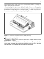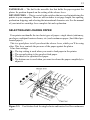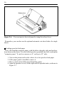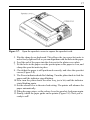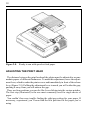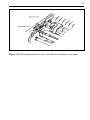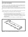
1
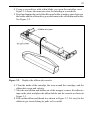
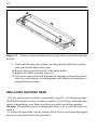
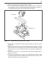
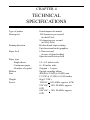
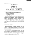
NL-10
USERS MANUAL
PN 80820108
Federal Communications Commission
Radio Frequency Interference
Statement
This equipment generates and uses radio frequency energy and if not installed and used
properly, that is, in strict accordance with the manufacturer’s instructions, may cause
interference to radio and television reception. It has been type tested and found to comply with the limits for a Class B computing device in accordance with the specifications
in Subpart J of Part 15 of FCC Rules, which are designed to provide reasonable protection against such interfernce in a residential installation. However, ther is no guarantee
that interfernce will not occur in a particular installation. If this equipment does cause
interference to radeo or television reception, which can be determined by turning the
equipment off and on, the user is encouraged to try to correct the interference by one or
more of the following measures:
• Reorient the receiving antenna
• Relocate the conputer with rewpect to the receiver
• Move the computer away from the receiver
• Plug the computer into a different outlet so that computer and receiver are on
different branch circuits.
If necessary, the user should consult the dealer or an experienced radio/television technician for additional suggestions. The user may find the following booklet, prepared by
the Federal Communications Commission helpful: “How to Identify and Resolve Radio-TV Interference Problems.” This booklet is available from the U.S. Govertnment
Printing Office, Washington, D.C., 20402, Stock No. 004-000-00345-4.
For compliance with Federal Noise Interference Standard, this equipment requires a
shielded cable.
This statement will be applied only for the printers marketed in U.S.A.
Self Declaration
Radio interferences regarding this equipment has been eliminated according to Vfg
1046/1984 announced by the DBP.
DBP has been informed about the introduction of this special equipment and has been
conceded the right to examine the whole series.
It is upon the responsibility of the user to assume that his own assembled system is in
accordance with the technical regulations under Vfg 1046/1984.
To observe FTZ-regulations it is necessary, to establish all connections to the printer
with shielded cable.
The equipment may only be opened by qualified service representatives.
This statement will be applied only for the printers marketed in West Germany.
Trademark Acknowledgement
NL-10: Star Micronics Co., Ltd.
NOTICE
• All rights reserved. Reproduction of any part of this manual in any form whatso
ever, without STAR’S express permission is forbidden.
• The contents of this manual are subject to change without notice.
• All efforts have been made to ensure the accuracy of the contents of this manual at
the time of going to press. However, should any errors be detected, STAR would be
greatly appreciate being informed of them.
• The above notwithstanding, STAR can assume no responsibility for errors in this
manual.
Copyright 1985 Star Micronics Co., Ltd.
A Special Message
to the New Owner
Congratulations! You are now the proud owner of one of the best dot-matrix
printers around. With a touch of your finger, you can choose fast, quality
draft printing or superb near-letter-quality printing. Despite its advanced
features, your printer is amazingly easy to use. And it’s compatible with nearly
every computer on the market by using a separated Interface Cartridge.
We hope you’ll find this manual easy and pleasant to use. It was master-minded
by experts in microcomputers and written by professionals skilled in presenting
technical details accurately - and in Plain English!
Take a look at the Table of Contents and you’ll see what we mean. Every important topic has a section of its own, and descriptions are clear but to the point.
You’ll find everything you need to know about the printer. We suggest that everybody take the time to scan Chapters 1 and 2 - the “Setting Up Your Printer” and
“Getting to Know Your Printer” - no matter how knowledgeable you are.
For those of you who want to learn everything you can about your printer, you’ll
have a ball! With an almost infinite variety of dot graphics to explore, you’ll find
the interface cartridge manual fascinating - special effects, control codes, and
dot graphics.
We’ve supplied plenty of short, interesting programs that show off the features
of your new printer - all written in BASIC that will run on most computers.
So, gentle reader, with this manual we hand you the key to the wonderful world
of dot-matrix printing. May you enjoy years of handsome, fast, and carefree printing!
Table of Contents
Chapter 1
Setting Up Your Printer
Where shall we put it?
What have we here?
Removing the printer cover
Removing the packing tube
Installing the ribbon cartridge
Installing the interface cartridge
1
Chapter 2
Getting to Know Your Printer
Controls and parts of the printer
Parts of the printer
Controls and indicators
Extra functions
Other controls
Selecting and loading paper
Loading single sheets
Loading sprocket-feed paper
Adjusting the print head
9
Chapter 3
Caring for Your Printer
Cleaning the printer
Replacing the ribbon
Replacing the print head
21
Chapter 4
Technical Specifications
27
Index
29
1
CHAPTER 1
SETTING UP YOUR
PRINTER
Subjects we’ll cover in Chapter 1 include• Choosing a suitable place for your printer;
• Unpacking your new printer;
• Setting it up.
WHERE SHALL WE PUT IT?
Before you do anything else, give some thought to where you’ll be using your
printer. Obviously, it will be somewhere near your computer. And both printer
andcomputer will lead longer, healthier lives if they like their surroundings. For
instance, we recommend...
• Using the printer on a flat surface.
• Keeping it out of direct sunlight and away from heat-producing appliances.
• Using it only in temperatures where you are comfortable.
• Avoiding areas with a lot of dust, grease, or humidity.
• Giving it “clean” electricity. Don’t connect it to the same circuit used by
large, noise-producing appliances (such as refrigerators).
• The line voltage should be within 10% of the voltage specified on the
identification plate.
2
WHAT HAVE WE HERE?
Now let’s take a look at what’s in the carton. Open it up and check each item in the
box against Figure 1-1. There should be four items.
Figure 1-1. Check to make sure you have all four items: 1) printer, 2) paper
guide, 3) ribbon cartridge, and 4) user’s manual.
In addition to your printer, you also need an Interface cartridge that connects
your computer to this printer.
These are sold separately because each brand of computer uses a different interface cartridge.
Removing the printer cover
The printer’s cover is important for two reasons-it keeps dust and dirt away
from the printer’s delicate mechanism, and absorbs nearly all of the printer’s
3
operating noise. Don’t take off the cover except when you have to change the
ribbon, or to make an adjustment.
Removing the printer cover is easy. Lift up the back of the cover to disengage the
two tabs at the front and then lift it off the rest of teh way. To replace it, just slide
the tabs in at the front and lower it into place. Figure 1-2 shows the proper position and movement for both removing and replacing the cover.
Figure 1-2. Remove the printer cover by lifting carefully.
Removing the packing tube
The printer is shipped with a protective spiral tube to keep the print head from
being damaged in transit.
We have to remove this tube. First, remove the printer cover. The protective tube
is split along its bottom side to allow easy removal. Grasp one end of the spiral
tube and firmly pull it upward and away from the carriage rail.
4
Figure 1-3. Remove the protective tube from the carriage rail.
Up to this point, we’ve been clearing the decks for action, so to speak. Only two
more things left to do before we can start printing - install the ribbon cartridge,
and the interface cartridge.
Installing the ribbon cartridge
This printer uses a neat, easy-to-change ribbon cartridge so you don’t have to
spend a lot of time threading a standard ribbon through the printer and getting
your hands all dirty to boot.
Telling you how to put in a ribbon is like telling you how to tie your shoelaces it takes a lot longer to describe it than it does to do it. So, you can just follow the
illustrations if you wish; they’ll tell you all you really need to know.
Or, if you feel better following written instructions, read on.
5
1. Turn off the power and remove the printer cover.
2. Now slide the print head gently to the center of the printer.
Warning: The print head gets hot during operation, so let it cool off before
you touch it.
3. Using the guide holders as a fulcrum with the ribbon facing away from
you, as shown in Figure 1-4, lightly press the cartridge down until the two
holder springs snap shut to hold the cartridge firmly in place.
4. Check that the cartridge fits so that the drive pins engage the cartridge teeth.
Figure 1-4. Press the cartridge into place until the holding springs snap into its
sides.
5. Gently slide the print head carriage manually all the way to your right or
left until the ribbon automatically slips down into its proper place between
the print head and the silver ribbon guide.
6
Figure 1-5. All you have to do is to slide the print head carriage manually to
your right or left, then the ribbon slips down by itself into its proper position.
6. Put the printer cover back on and you’re finished. (A special switch on the
printer prevents the printer from working when the cover is off.)
Installing the interface cartridge
A special interface cartridge contains all the electronics your printer needs to
talk to a computer. To use your printer with a different computer, just install a
different cartridge. There is an interface (I/F) cartridge for each popular computer
on the market.
If you have the correct I/F cartridge for your computer, we can start by turning
the printer around. Facing the back of it, you’ll notice an opening at the left end.
This is where the cartridge goes.
Turn off the power switch, and fit the I/F cartridge into the space as shown, with
the triangles on the cartridge toward the printer and slide it in all the way (don’t
force it). If the connector is seated snugly in its socket, you should be able to
7
Figure 1-6. Slide the I/F cartrige into the slot.
tighten the screw easily. When this is done, connect the cable from your computer
and you’re ready to go.
8
MEMO
9
CHAPTER 2
GETTING TO KNOW
YOUR PRINTER
Subjects we’ll cover in Chapter 2 include • Parts of the printer - what they’re for and how to use them;
• Paper selection and loading;
• Adjustment.
CONTROLS AND PARTS OF THE PRINTER
Parts of the printer
First, we’ll go over the parts of the printer. You saw most of these when you
unpacked your printer. Now we’ll give you a brief explanation of what they do.
(For details on the initial set-up of this printer, with all components in place, see
Chapter 1.)
PRINTER COVER - This protects the ribbon and the print head from dust and
dirt, and cuts down the sound of the printer.
PAPER GUIDE - As you’ve guessed, this flat plastic molding guides the paper
during printing (it is raised for single sheets and lies flat for sprocket-feed paper).
POWER CORD - This cord connects the printer to its power souce, usually a
wall outlet. It’s located at the left rear of the printer.
PRINT HEAD - This is the unit that does the actual printing. Like the strike
lever in a typewriter, tiny, stiff wires in the print head hit the paper through a
ribbon.
TRACTOR FEED UNIT - The drive gear and sprockets of the tractor feed unit
move sprocket-feed paper through the printer.
PLATEN - This is the rubber cylinder that carries paper to the print head.
10
Figure 2-1. Front and rear views of the printer
INTERFACE COMPARTMENT - On the back of the printer, this space holds
the interface cartridge for your computer.
11
Controls and indicators (More detail of panel of panel operation keys and Control codes can be found in Interface Cartridge manual.)
Now let’s go over the controls and indicators of the printer, starting with the
control panel on the right. There are seven indicators and five keys on the control
panel.
Figure 2-2. The control panel.
POWER INDICATOR - Glows red when the power in on or blinks when the
printer is out of paper or some other error occurs.
BOLD KEY and INDICATOR - Pressing this key selects boldface printing.
DRAFT INDICATORS (80, 96, 136) - Glows green to indicate the number of
characters per line when the priner is in the draft mode (set by the Mode key or the
software control).
NLQ INDICATOR - Glows green when the printer is printing in the Near
Letter Quality (NLQ) mode (set by the Mode key or the software control).
MODE KEY - Changes the print mode every time it is pressed.
TOF KEY - Ejects the current sheet, feeds a new sheet, and moves the print
head to the left margin.
PAPER FEED KEY - Advances the paper one line at a time when the On Line
indicator is off. If you hold the key down, you’ll get consecutive line feeds, one
after the other.
ON LINE KEY and INDICATOR - Glows green when the printer is ready to
receive data from your computer (on line). When the printer is off line, it sends a
signal to the computer indicating that it cannot accept data. Pressing the On Line
key switches the printer on line and off line.
Extra functions
There are seven more functions that are not directly specified on the control
panel. You can use three of them by pressing a key when you turn on the power;
four others are activated by pressing two control keys at once. Here’s a summary:
12
WHILE TURNING ON THE POWER
Test print 1 (long form) - Holding down the Paper Feed key causes the printer
to output the full test print.
Test print 2 (short form) - Holding down the On Line key causes the printer to
output theabridged test print.
Hex dump - Holding down both the Paper Feed key and Mode key puts the
printer into the hex dump mode (more on this in the programming manual).
DURING NORMAL OPERATION
Micro-feed - Pressing the Paper Feed key while holding down the On Line key
feeds paper in the normal direction in 1/72” increments.
Reverse micro-feed - Pressing the TOF key while holding down the On Line key
feeds paper in the reverse direction in 1/72” increments.
Right margin - When holding down the Mode and pressing Paper Feed keys the
print head goes to the right end immediately and returns to the left slowly. Releasing the Paper Feed key sets the right margin to where the print head is.
Left margin - When holding down the Mode and pressing TOF keys the print
head moves to the right slowly. Releasing the TOF key sets the left margin to
where the print head is.
Other controls
There are other controls, not connected to the control panel board. Some of the
more important ones are:
POWER SWITCH - The switch that turns the printer on and off is at the back,
on the left side.
PLATEN KNOB - This knob is at the middle of the right side and lets you turn
the platen by hand, just like a typewriter.
Caution: Turn this knob only with the Power switch off. Turning it with the power
on could damage the platen drive gears.
RELEASE LEVER - The release lever is on top of the pritner, near the left rear
corner. You’ll be using it often - it controls how strongly the paper is held against
the platen. The release lever has four positions: the top setting is used for inserting
paper, the next is for single sheets, the third is for sprocket-feed paper, and the
bottom one is used when adjusting the paper.
13
PAPER BAIL - The bail is the movable bar that holds the paper against the
platen. Its position depends on the setting of the release lever.
DIP SWITCHES - This is a set of eight switches that are used in interfacing the
printer to your computer. There are also switches to set page length, line spacing,
perforation skipping, and selecting the international character sets. See the manual
of your interface cartridge for a complete list and explanation.
SELECTING AND LOADING PAPER
Your printer can handle the two basic types of paper-single sheets (stationery,
envelopes, multipart business forms, etc.) and continuous paper (fan-folded perforated paper).
This is a good place to tell you about the release lever, which you’ll be using
often. This lever controls the pressure of the paper against the platen.
It has four settings:
- The top setting is used when you want to load paper in the printer.
- The second setting is for sprocket-feed paper.
- The third is for sprocket-feed paper.
- The bottom one is used when you want to release the paper completely to
adjust it.
Figure 2-3. Use friction feed for single sheets and tractor feed for continuous
paper.
14
The paper bail holds the paper against the platen according to the setting of the
release lever. The bail is opened when the release lever is in the top position,
closed when the lever is in the second or third positions, and opened by the printer
when the lever is in the bottom position.
Loading single sheets
Now, instead of feeding the paper in manually by turning the platen knob, we’re
going to use the release lever (the printer must be turned on). Remember what we
told you about this lever? It allows you to advance the paper according to its
position.
OK? Let’s start.
1. Flip the clamp levers backward and remove the sprockets on the tractor
feed unit all the way to the ends.
2. Slide the sheet guide all the way to the right.
3. With the ribs of the paper guide toward you and the sliding adjuster at the
bottom left, insert the guide into the slot at the back of the printer cover.
4. Insert the guide stand in the notches provided for it and use it to prop up
the paper guide.
5. Position the adjuster at the triangle marked on the guide for standard
margins, or set it according to your requirements.
6. Set the release lever for single sheets - the second position from the top.
7. Align a sheet of paper on the guide along the adjuster.
8. Turn on the power switch. (The Power indicator will blink because there
is no paper.)
9. Now set the release lever to the auto-feed setting - the top position. The
printer will advance the paper automatically.
10.When the paper stops, set the release lever for single sheets again.
To align paper that is not in straight • Set the release lever to the adjustment setting.
• Straighten the paper and adjust it for the margins you want.
• Move the releae lever back to its original setting.
15
Figure 2-4. Raise the paper guide for loading single sheets.
Figure 2-5. Prop up the paper guide by inserting the guide stand in the notches
provided for it.
16
Figure 2-6. You can insert a sheet of paper by using the release lever.
Remember, you can also use the optional automatic cut-sheet feeder for single
sheets.
Loading sprocket-feed paper
This is the familiar computer paper, with the holes along the sides and perforations between the sheets. It is also called sprocket, punched, fan-fold, or just plain
“computer paper.” It can be as narrow as 4”, and up to 10” wide.
1. Turn on the printer and set the release lever for sprocket-feed paper.
2. If the paper guide is installed, remove it.
3. Place a stack of fan-fold paper behind the printer.
4. Open the sprocket covers, on the right and left sprocket units, as shown in
Figure 2-7.
17
Figure 2-7. Open the sprocket covers to expose the sprocket teeth.
5. Flip the clamp levers backward. This allows the two sprocket units to
move freely right and left so you can align them with the holes in the paper.
6. Feed the end of the paper into the slot next to the platen cover plate.
7. Fit the holes in the paper over the sproket pins so the paper is even, and
clamp the sprocket units in place.
8. Check that the paper is still positioned correctly, and close the sprocket
covers (Figure 2-8)
9. The Power indicator should be blinking. Turn the platen knob to feed the
paper until the indicator stops blinking.
10.Now turn the platen knob the other way just a bit, until the indicator
starts blinking again.
11.Set the release lever to the auto-feed setting. The printer will advance the
paper automatically.
12.When the paper stops, set the release lever for sprocket-feed paper again.
13.Finally, install the paper guide on the printer (Figure 2-8). Now you’re
ready to roll!
18
Figure 2-8. Ready to run with sprocket-feed paper.
ADJUSTING THE PRINT HEAD
The distance between the print head and the platen must be adjusted to accommodate papers of different thicknesses. To make this adjustment, move the adjustment lever, which is under the printer cover and immediately in front of the release
lever (Figure 2-9). Pulliing the adjustment lever towards you will widen the gap;
pushing it away from you will narrow the gap.
There are four positions; you can feel the lever clicking into the various notches.
The first step (illustrated) is the one most commonly used for single sheets of
paper.
You souldn’t have any trouble finding the right gap setting for your paper. If
necessary, experiment; you’ll soon find the best position for the paper you’re
using.
19
Figure 2-9. The adjustment lever allows for different thicknesses of paper.
20
MEMO
21
CHAPTER 3
CARING
FOR YOUR PRINTER
As any good mechanic will tell you, dust and heat are the biggest enemies of
every mechanism. And your printer is no exception. The best maintenance is preventive maintenance, so the first step in keeping your printer healthy and happy is
to make sure it’s in a clean, dust-free location. The range of temperature should be
comfortable for both you and your computer/printer system. (Please refer to Chapter
1 for more tips on locating your printer.)
Subjects we’ll cover in Chapter 3 include• Cleaning the printer;
• Changing the ribbon;
• Replacing the print head.
CLEANING THE PRINTER
Another important rule for keeping your printer young and healthy is to clean it
regularly- inside and out. Just use a damp towel every week or so (you can
moisten the towel with alcohol for stubborn dirt, but be careful not to get any
alcohol on the printer mechanism).
Use a soft brush to remove dust and lint from inside the printer, but be very
careful not to bend or injure any electronic parts or wiring. It doesn’t take much to
do expenseve damage, so don’t fuss where you’re not supposed to-besides periodic cleaning, the only other maintenance you’ll have to do will be changing the
ribbon cartridge, or the print head.
22
REPLACING THE RIBBON
This printer uses an “endless” ribbon cartridge, which means that the inked ribbon inside is recycled automatically. Eventually, though, printing will become too
faint to read easily and you’ll want to change the ribbon.
However, it is less expensive and more economical to replace only the ribbon
portion inside the cartridge. If this money saving method does interest you, read
on.
Follow this procedure to remove the old ribbon and insert the new one in the
original cartridge (not recommended for people with ten thumbs!).
1. First, obtain from your dealer the correct type of ribbon “sub-cassette”
(not the spool-type ribbons used with some other printers).
2. Grasp both ends of the ribbon cartridge and pull the cartridge up and out
of the printer. (Refer to Chapter 1 for illustrations of installing the refilled
ribbon cartridge.)
3. Unhook the six tabs of the cartridge cover carefully (Figure 3-1).
Figure 3-1. Use a screwdriver to pry open the cartridge.
23
4. Using a screwdriver with a thin blade, pry open the cartridge cover.
Figure 3-1 shows the numerous slots for inserting a screwdriver.
5. Press hard against the end of the idler gear holder to make a space between
the holder and the ribbon drive gear, and remove the old ribbon and holder.
See Figure 3-2.
Figure 3-2. Replace the ribbon sub-cassette.
6. Clean the inside of the cartridge, the area around the cartridge, and the
ribbon drive gear and vicinity.
7. Take the new ribbon and holder out of the wrapper, remove the adhesive
tape on the joint, and place the ribbon holder into the cassette as shown in
Figure 3-3.
8. Pull out the ribbon and thread it as shown in Figure 3-3. It’s easy for the
ribbon to get twisted along its path, so be careful.
24
Figure 3-3. Make sure that the ribbon is not twisted when you thread it through
its path.
9. Firmly pull the idler gear towrds you and guide the ribbon between the
idler gear and the ribbon drive gear.
10.Remove the top and the bottom of the ribbon holder.
11.Replace the ribbon cartridge top cover.
12.Now you’re almost finished! Remount the cartridge to the printer. Notice
that five replacements is the maximum, after which you should buy a
completelt new cartridge.
REPLACING THE PRINT HEAD
The dot matrix print head has a remarkably long life. It will print perhaps
100,000,000 characers before you have to replace it. You’ll know when that time
comes when printing is too faint even after you replace the ribbon cartridge.
Warning: The print head gets hot during operation, so let it cool off before you
touch it.
To replace the print head, start by turning off the Power switch and unplugging
the power cord. Then follow this procedure:
25
1. Remove the printer cover and the ribbon cartridge.
2. Remove the print head left along the carriage, until you can see the connector
cover. Remove the cover from the printer frame; for datails, see Figure 34. Unplug the print head cable from the head cable board.
Figure 3-4. Replacement of the print head is simple.
3. Hold back the tab that locks the print head into place, and remove the
print head.
4. Making sure that the new print head is facing the correct direction, carefully
plug the cable into the connector on the head cable board. Make sure that
this connection is secure, and that the cable is inserted far enough into the
conector.
5. Replace the connector cover, and feed the cable under the support tab on
the top of the cover.
6. Fit the new print head into its support, while holding the tab back. Make
sure that the print head is inserted into its guides as far as it can go, and
that the tab locks the print head into place.
26
MEMO
27
CHAPTER 4
TECHNICAL
SPECIFICATIONS
Type of printer
Print speed
Printing direction
Paper feed
Paper type
Single sheets
Continuous paper
(Number of copies)
Ribbon
Size
Weight
Power
Serial impact dot matrix
120 characters per second
(in draft Pica)
30 characters per second
(in NLQ Pica)
Bi-directional, logic seeking
Uni-directional in dot graphics
14 lines/second
(in case of form feeding)
Sprocket and Friction feed
5.5-8.5 inches wide
4-10 inches wide
Original + 2 copies
Special cartridge ribbon
400(W) x 336(D) x 104(H) mm
15.7(W) x 13.2(D) x 4.1(H) inches
6kg (13.2lb.)
120VAC + 10% 60Hz, approx. 65W
220 VAC + 10% 50/60Hz, approx.
65W
240 VAC + 10% 50/60Hz, approx.
65W
28
MEMO
29
INDEX
adjustment, 18
alcohol, cleaning with, 21
automatic cut-sheet feeder, 16
release lever, 12
reverse micro-feed, 12
ribbon, replacing the, 22
right margin, 12
Bold key and indicator, 11
cleaning the printer, 21
control panel, 11
DIP switches, 13
Draft indicators, 11
fuse, 25
fuse, replacing a, 24
guide stand, 14
hex dump
interface cartridge, 6
interface compartment, 10
left margin, 12
loading paper, 13
single sheets, 14
sprocket-feed paper, 16
micto-feed, 12
Mode key, 11
NLQ indicator, 11
On Line key and indicator, 11
packing tube, 3
paper bail, 13
Paper Feed key, 11
paper guide, 9
platen, 9
platen knob, 12
Power indicator, 11
Power switch, 12
printer cover, 9
print head, 9
print head, adjusting the, 18
print head, replacing the, 26
spacifications, 27
suitable place, 1
test print, 12
TOF key, 11
tractor feed unit, 9