1
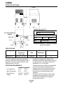
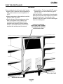
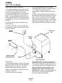
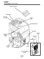
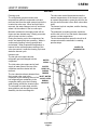
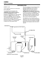
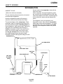
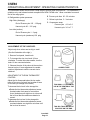
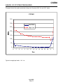
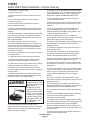
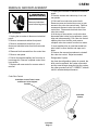
CSE60
INTRODUCTION
This service manual covers the installation,
operation, maintenance and service of this ice
machine.
Table of Contents
SPECIFICATIONS· · · · · · · · · · · · · · · · · · · · · · · · · · · · · · · · · · · · · · · · · Page 2
FOR THE INSTALLER · · · · · · · · · · · · · · · · · · · · · · · · · · · · · · · · · · · · · · Page 3
FOR THE PLUMBER · · · · · · · · · · · · · · · · · · · · · · · · · · · · · · · · · · · · · · · Page 4
INSTALLATION · · · · · · · · · · · · · · · · · · · · · · · · · · · · · · · · · · · · · · · · · · Page 5
INITIAL START UP · · · · · · · · · · · · · · · · · · · · · · · · · · · · · · · · · · · · · · · · Page 6
HOW IT WORKS: · · · · · · · · · · · · · · · · · · · · · · · · · · · · · · · · · · · · · · · · · Page 7
COMPONENT LOCATION · · · · · · · · · · · · · · · · · · · · · · · · · · · · · · · · · · · · Page 8
HOW IT WORKS: · · · · · · · · · · · · · · · · · · · · · · · · · · · · · · · · · · · · · · · · · Page 9
HOW IT WORKS: · · · · · · · · · · · · · · · · · · · · · · · · · · · · · · · · · · · · · · · · · Page 10
HOW IT WORKS: · · · · · · · · · · · · · · · · · · · · · · · · · · · · · · · · · · · · · · · · · Page 11
OPERATION & ADJUSTMENT: OPERATING CHARACTERISTICS · · · · · · · · · · · · · · · Page 12
GRAPH OF SYSTEM PRESSURES · · · · · · · · · · · · · · · · · · · · · · · · · · · · · · · Page 13
SANITIZING AND CLEANING · · · · · · · · · · · · · · · · · · · · · · · · · · · · · · · · · · Page 14
SERVICE DIAGNOSIS · · · · · · · · · · · · · · · · · · · · · · · · · · · · · · · · · · · · · · Page 15
SERVICE DIAGNOSIS · · · · · · · · · · · · · · · · · · · · · · · · · · · · · · · · · · · · · · Page 16
REMOVAL AND REPLACEMENT· · · · · · · · · · · · · · · · · · · · · · · · · · · · · · · · · Page 17
REMOVAL AND REPLACEMENT· · · · · · · · · · · · · · · · · · · · · · · · · · · · · · · · · Page 18
Service Parts lists and Wiring diagrams are located in the center of this manual, printed on
yellow paper.
This manual was printed on recycled paper.
Keep this manual for future reference.
Note the Warning symbol, it marks a possible hazard.
June 2001
Page 1
CSE60
SPECIFICATIONS
17 9/16"
28 9/16"
5" to
5.5"
18"
20.5"
NAMEPLATE LOCATION
SCOTSMAN
MODEL
3/4" HOSE COUPLING
THREAD
SERIAL
25/32" OD
POWER
CORD
2 .2"
2 .2"
1 .76"
SPECIFICATIONS
Model Number
VOLT
PHASE
Oz
REFRIGERANT
Refrigerant Charge is 9 ½ oz of R-134a. Always
go by the nameplate.
3.83"
5 .4"
Dimensions
H" X W" X D"
Cube
Size
Basic
Electrical
Max. Fuse Size
28.56 X 18 X 20.5
Medium
115/60/1
15
W/out legs
CSE60A-1A
AMP
Hz
The finish is stainless steel with a galvanized
back panel. Minimum circuit ampacity is used to
determine wire size per national electric code.
Refrigerant type is R-134a.
Scotsman Ice Systems are designed and
manufactured with the highest regard for safety
and performance. They meet or exceed the
standards of UL, CUL and NSF.
OPERATING REQUIREMENTS:
Scotsman assumes no liability or responsibility
of any kind for products manufactured by
Scotsman that have been altered in any way,
including the use of any parts and/or other
components not specifically approved by
Scotsman.
MINIMUM MAXIMUM
Air Temperature
500 F.
1000 F.
Water Temperature
400 F.
1000 F.
Water Pressure
20 PSIG
100 PSIG
Voltage
103.5V
126.5V
Scotsman reserves the right to make design
changes and/or improvements at any time.
Specifications and designs are subject to
change without notice.
June 2001
Page 2
CSE60
FOR THE INSTALLER
Location:
Prior consideration for the location shall include:
· Indoors, with a minimum room temperature of
500F. and a maximum room temperature of
1000F.
· Water temperature to the machine should be
between 400F. and 1000F.
· Service Access. Allow enough space at the
back of the cabinet for the utilities to be
connected. Allow enough space for the
machine to be pulled out from its installed
location. Do not build a floor in front of the
machine that would prevent its removal.
· Air circulation:
The front panel MUST remain
unobstructed. Do not block with any type of
door or curtain.
If the unit is built in, it will pull air in from the right
side of the front panel, and exhaust it out the left
side of the front panel. If the left side of the
machine is left open, warm air will be discharged
from the left side panel.
IF BUILT IN, THIS SIDE
SHOULD BE TIGHT AGAINST
THE CABINET TO PREVENT
AIR RECIRCULATION
COOL AIR INTAKE
WARM AIR DISCHARGE
June 2001
Page 3
CSE60
FOR THE PLUMBER
Water supply and drain connections.
1. The recommended water supply line is a 1/4"
o.d. copper tube, the water pressure must have
a minimum incoming pressure of 20 psig.
2. Connect the tubing to the 3/4" hose coupling
thread water inlet fitting at the back of the ice
maker. An optional adapter to go from the 3/4"
hose coupling thread to 1/4" compression fitting
is available from your dealer under part number
02165477.
Or a similar adapter can be purchased from a
hardware store.
4. Connect a gravity drain line to the drain
connection at the ice maker. A minimum slope
of 1/4" fall per foot of horizontal run is
recommended. Install the drains per the local
codes.
A vent is recommended on the highest point of
the drain tube, and the drain tubing must be rigid
pipe. Do NOT use flexible tubing for the entire
drain system. A short section of ¾ “ ID flexible
tubing and suitable hose clamps may be used to
interconnect a rigid drain system to the .78” OD
(20 mm) plastic drain fitting on the ice machine.
3. Install a shut off valve in the incoming water
line near the ice maker so that the water can be
shut off for service.
POWER
SUPPLY
LEVEL THE
UNIT
POWER
CORD
WATER
SUPPLY
SHUT
OFF
WATER FILTER
(FIELD SUPPLIED)
DRAIN
ADAPTER
(FIELD SUPPLIED)
ELECTRICAL
1. Locate the nameplate on the lower rear panel
and check that the location source voltage and
capacity are correct for this unit. The unit is
equipped with a grounded plug connection.
Under no circumstances must the ground post
be altered or removed.
Extension cords are not permitted.
Be certain that the ice maker is connected to its
own electrical circuit and is individually fused.
The maximum allowable voltage variation should
not exceed ten percent of the nameplate rating.
All external wiring should conform to the
National, State, and local electrical code
requirements. Usually an electrical permit and
the services of a licensed electrician will be
required to install the receptacle.
June 2001
Page 4
CSE60
INSTALLATION
FINAL CHECK
1. Is the Cabinet level?
2. Have all the electrical and piping connections
been made?
3. Has the voltage been tested and checked
against the nameplate rating?
6. Have the bin interior, and the cabinet exterior
been wiped clean?
7. Are all internal parts in place, including the
spray platform and curtain?
8. Have the internal refrigerant lines been
checked for rubbing and chaffing?
4. Is the unit plugged into a separate electrical
circuit?
5. Is the water supply line shut off valve installed
and is the water turned on?
9. Has the machine been installed where it is
indoors, in a controlled environment, with
adequate air circulation around the machine,
and where it can be serviced?
POWER?
LEVEL?
DRAINS?
WATER?
June 2001
Page 5
CSE60
INITIAL START UP
1. Open water supply valve.
If the cubes are overfilled, adjust the machine to
make smaller ice cubes by turning the cube size
control counter-clockwise.
2. Move electrical breaker or switch to the on
position.
In both cases, the next cycle of cubes harvested
must be observed, and further corrections may
be needed.
3. Remove front panel.
4. Check the cube size control shaft, it should be
in a preset cube size position. If not, turn it
clockwise until the unit comes on. Note: cube
size adjustments may be required. Start with the
shaft in the “mid” position.
5. The machine will go thru a “dry” cycle, this will
take about 10 minutes. Then the water fill and
harvest cycle will begin.
6. Observe the water fill cycle:
· The water inlet valve opens.
· Incoming water flows from the valve through
the tubing to the top of the ice maker.
· Water flows around the inverted ice cube
cups and drains through holes into the
reservoir.
· The reservoir begins to fill up with water.
· Water continues to enter the machine and
overflows a standpipe in the reservoir and
down the drain.
This will take about 3 minutes. After that the
freeze cycle will begin.
7. Check the operation of the freezing cycle:
If the ice cubes are cloudy, an extreme water
condition may exist. Confirm that they are
cloudy by placing them in a glass of cold water.
If, in the water, they remain cloudy, you may
want to have the water tested by a water
treatment specialist.
If the ice cubes are cloudy only on the bottom or
in the center, the machine may be running out of
water before the end of the freezing cycle.
10. Test the bin full shut off. To test this, hold
some ice on the bin thermostat bracket (the
stainless steel tube on the left side of the ice
storage bin). The ice maker should stop within a
few minutes of having ice on that tube.
11. Fill out the Warranty Registration and
Customer Evaluation form, and mail it to
Scotsman.
12. Make sure the user understands the
operation and maintenance requirements for the
ice maker. Leave the service manual and the
name of the local Scotsman service agency with
the user.
· Compressor is running.
· Water pump is spraying water through the
spray nozzles.
· Ice making
begins, the water gets very cold,
and ice begins to form in the cube molds.
8. Check that the plastic curtain assembly hangs
down evenly in the opening and that no large
streams of water are passing through.
Note: Some water will drip from the reservoir as
the machine runs. This is normal.
9. After about 20 minutes the machine will begin
to release the ice, this is called the harvest
cycle.
Observe the first cube harvest:
· Check the size of the ice cubes.
Note: The normal size of the ice cube has a 1/4"
depression in the wide end.
If the cubes are not filled out, adjust the machine
to make larger ice cubes by turning the cube
size control shaft clockwise.
June 2001
Page 6
CSE60
HOW IT WORKS:
COMPONENT DESCRIPTION
Bin Thermostat Control
Cube Size Control
The cube size control is located in front of the
control box, behind the front panel. The sensing
capillary tube of the cube size control is routed
out of the control box into its bulb holder on the
evaporator coil. It is a reverse acting
temperature control with double throw contacts.
Turning its knob all the way counterclockwise
also shuts off the ice maker.
The control determines the length of the freezing
cycle and correspondingly the size of the cube.
A lower setting will produce a smaller cube, and
a higher setting will make a larger cube. The
cube size control changes its contacts when the
evaporator reaches its preset temperature,
starting the harvest cycle. When the sensing
tube of the cube size control reaches the high
preset temperature, the contacts change again,
restarting the freeze cycle.
Compressor Toggle Switch.
The compressor toggle switch is located on the
side of the control box. When moved to the ON
position, it makes a circuit to the compressor.
When moved to the OFF position, the other
components will still operate.
High Temperature Cut Out
This control senses the temperature of the
discharge line and will open to stop the
operation of the ice machine should the
discharge temperature exceed the preset
maximum (175oF). After it cools to 140oF. it must
then be manually reset to restart the machine by
pushing the button at the front of the control box.
Water Pump
The bin thermostat control body is located in
front of the control box just beside the cube
size control. The thermostat sensing tube is
located in the ice storage bin on the left side wall
where is automatically shuts the ice maker off
when the bin is full and restarts when ice is
removed. Factory settings are 1 degree C (36
degrees F) cut out and 4 degrees C (39 degrees
F) cut in. It can be adjusted by turning the
adjustment screw visible through the control box
cover.
Hot Gas Valve Assembly
The hot gas valve assembly is comprised of two
parts, the valve body and the coil. These parts
are located on the discharge line of the
compressor and are activated by the cube size
control (harvest cycle). When the coil of the hot
gas valve is energized, it magnetically lifts the
plunger in the hot gas valve body. This allows
hot refrigerant gas to by-pass the condenser and
go directly to the evaporator.
Spray Platform and Chute
The spray system used on this unit is of the
stationary type. The water is forced by the
water pump into the platform chamber and
sprayed into the inverted cup molds through a
set of six spray nozzles.
Fan Motor
The fan motor is electrically connected through
the cube size control and runs only during the
freezing cycle.
Hermetic Motor Compressor
The compressor is a vapor pump, forcing
refrigerant gas throughout the refrigeration
system.
The water pump operates during the freezing
cycle only, pumping water through the spray
nozzles into the inverted spray cups.
Inlet Water Solenoid Valve
The water solenoid valve, located in the back
panel of the unit, is energized only during the
harvest or cleaning cycles. When energized it
allows a metered amount of water to flow into
the machine (.21 g.p.m.) This water flows to the
top of the evaporator and then down into the
reservoir.
June 2001
Page 7
CSE60
COMPONENT LOCATION
SPRAY PLATFORM
EVAPORATOR
RESERVOIR
FILL TUBE
WATER
PUMP
WATER RESERVOIR
BIN DRAIN
CONTROL
BOX
BIN LEVEL
CONTROL
TUBE
High Temp
Cut Out
BIN
THERMOSTAT
HOT GAS
VALVE
CUBE
SIZE
&
ON/OFF
WATER
INLET
VALVE
COMPRESSOR
CLEAN / OPERATE
SWITCH
June 2001
Page 8
CSE60
HOW IT WORKS:
WATER
Freezing cycle
The refrigeration process creates cold
temperatures within the evaporator coils and
removes heat from the water sprayed up into the
inverted ice cube cups. When enough heat is
removed, the water changes into ice, and forms
where it is the coldest: in the ice cube cups.
The cube size control thermostat senses the
warmer temperatures of the harvest cycle, and
at a preset temperature, opens the circuit to the
hot gas and inlet water valves. Both valves then
close.
The harvest cycle is complete, and the freezing
cycle restarts.
Minerals contained in the supply water will not
freeze and are drained away. Mostly pure water
will be frozen into the ice cubes.
The automatic ice making process continues
until the bin is full of ice, and the bin thermostat
senses a colder temperature.
During the freezing cycle, the compressor, fan
motor, and water pump are operating. Water is
continuously freezing or being sprayed and
recirculated. When evaporator temperature is
lowered to the cold temperature setting of the
cube size control, it ends the freezing cycle and
starts the harvest cycle.
The bin thermostat then opens the circuit to all
components and the automatic ice making
process stops.
WATER TO
EVAPORATOR
Harvest cycle
The hot gas valve opens and hot
refrigerant gas is discharged into the
evaporator.
The inlet water valve opens and a fresh
supply of water flows to the top of the
evaporator and then drains into the
reservoir.
WATER
SPRAY
WATER
PUMP, ON
DURING
FREEZE
The ice cubes have been released from
the inverted cube cups in the
INLET WATER
evaporator by the warming effect of the VALVE, OPEN
hot refrigerant gas condensing in the
DURING
evaporator tubing, plus the incoming
HARVEST
water flowing around the inverted cups.
The released ice cubes drop onto the
spray platform and through the curtain
assembly into the ice storage bin.
DRAINS
June 2001
Page 9
CSE60
HOW IT WORKS:
REFRIGERATION
FREEZE CYCLE
The ice cubes are formed in an inverted mold
that is refrigerated.
The refrigeration process begins at the
compressor. There, refrigerant vapor is
compressed and flows from the compressor
through the discharge line as a high
temperature, high pressure gas. In the discharge
line there is a strainer with two outlets, one
leads to the condenser, and one to a solenoid
valve. Because the solenoid valve is closed, the
gas flows to the condenser, where heat is
transferred from the refrigerant to the air passing
through the condenser. The refrigerant then
condenses into a high pressure liquid.
From the condenser, the liquid refrigerant flows
through the liquid line, and the liquid line
filter-drier. After the filter drier, the liquid
refrigerant enters the metering device, a
capillary tube. After passing the restriction of
the capillary tube, the refrigerant enters an area
of relative low pressure, the evaporator. In the
tubing of the evaporator, the liquid refrigerant
expands and evaporates, absorbing heat from
the evaporator tubing and anything in contact
with it such as water sprayed against it.
The refrigerant, now a low pressure, low
temperature vapor, flows into the accumulator,
which traps excess liquid refrigerant. The vapor,
now primarily a gas, goes through the suction
line tube to the compressor where the cycle is
repeated.
EVAPORATOR
ACCUMULATOR
CAPILLARY TUBE
DISCHARG
E LINE
SUCTION
LINE
CONDENSER
LIQUID
LINE
COMPRESSOR
STRAINER
Refrigeration System Schematic
June 2001
Page 10
FILTER-DRIER
CSE60
HOW IT WORKS:
REFRIGERATION
hot gas valve to the evaporator, where the ice
cubes are frozen.
HARVEST CYCLE
(When the cubes are released)
At the evaporator, the high temperature gases
are cooled by the cold temperatures of the cube
mold, and condense into liquid, transferring heat
to the mold which warms up and releases the
cubes.
The ice cubes have been formed in an inverted
mold that was refrigerated.
Now the refrigeration system will change to
warm the cube mold and release the cubes.
The process begins at the compressor. There,
refrigerant vapor is compressed and flows from
the compressor through the discharge line as a
high temperature, high pressure gas. Before the
gas gets to the condenser,it goes through a
strainer, the strainer outlet is connected to two
tubes, one of which leads to an electric valve,
the hot gas solenoid. When this valve opens,
the refrigerant gas follows the path of least
resistance and flows through the tubing from the
The refrigerant, now a low pressure, low
temperature vapor, flows into the accumulator,
which traps excess liquid refrigerant. The vapor,
now primarily a gas, goes through the suction
line tube to the compressor where the cycle is
repeated.
EVAPORATOR
ACCUMULATOR
CAPILLARY TUBE
HOT GAS
SOLENOID
(OPEN)
DISCHARGE LINE
SUCTION
LINE
CONDENSER
LIQUID
LINE
COMPRESSOR
STRAINER
June 2001
Page 11
FILTER-DRIER
CSE60
OPERATION & ADJUSTMENT: OPERATING CHARACTERISTICS
The information shown below covers a wide range of air and water temperatures. It is intended as a
guideline only, and is based on data compiled from NEW CLEAN units. Allow a variation from each
end of the range given.
B. Freeze cycle time 20 - 25 minutes
A. Refrigeration system pressures:
C. Defrost cycle time 2 - 3 minutes
High Side (discharge)
D. Compressor amps
End of Freeze cycle 125 - 130 psig
Freeze cycle 4.3 to 3.6
Harvest cycle 83 - 125 psig
Harvest cycle 3.6 to 7.7
Low side (suction)
End of Freeze cycle 1 - 3 psig
Harvest cycle (maximum) 120 psig
ADJUSTMENT OF THE CUBE SIZE:
Adjust only when cubes are too big or small.
(See the illustration at the right.)
1. Remove front panel, locate knob.
2. To increase the size, turn knob 1/8 turn
clockwise. To make the cubes smaller, turn the
knob 1/8 turn counterclockwise.
3. Observe the size of the cubes in the next two
harvest cycles, if more adjustment is needed,
continue adjustments until the correct size is
obtained.
CORRECT SIZE
ADJUSTMENT OF THE BIN THERMOSTAT
CONTROL
Adjust the bin thermostat when the ice maker
turns off too soon (ice level low) or when it turns
off too late (ice storage bin overfills.)
To increase the ice level in the storage bin:
· Rotate the bin thermostat adjustment screw
TOO SMALL, LITTLE OR NO
ICE IN THE CENTER OF THE
CUBE.
(located under front panel on control box
cover) clockwise one eight turn at a time until
the ice level that the machine maintains is
correct.
To decrease the ice level in the storage bin:
· Rotate the bin thermostat adjustment screw
counterclockwise one eight turn at a time until
the ice level is correct.
June 2001
Page 12
TOO BIG, THICK BULGE OF
SOLID ICE ON THE END.
CSE60
GRAPH OF SYSTEM PRESSURES
This graph shows the system pressures during one full cycle at 90oF. Air and 70oF. water.
CSE60
350
300
Low Side
High Side
250
200
150
100
50
0
0
2
4
6
8
10 12 14 16 18 20 22 24
Time
Typical ice weight per batch: 1 lb. 1 oz.
June 2001
Page 13
0
2
CSE60
SANITIZING AND CLEANING: In Place Cleaning
1. Remove the ice from the bin.
2. Remove front panel.
3. Rotate control knob counter clockwise to the Off
position.
4. Turn off the water supply to the ice machine.
5. Remove top panel.
To sanitize, mix a locally approved sanitizer solution
and perform steps 17-31. A possible sanitizer solution
may be obtained by mixing 1 ounce of household
bleach with 2 gallons of warm (95-115oF) water.
17. Remove plastic panel (evaporator cover) that
covers evaporator section.
18. Remove curtain by pulling forward on the left end,
and then pulling the curtain to the left and out of the
machine.
6. Remove plastic panel (evaporator cover) that
covers evaporator section.
7. Remove curtain by pulling forward on the left end,
and then pulling the curtain to the left and out of the
machine.
8. Lift up spray platform, locate stand pipe to the right
of the opening, and pull it out to drain the reservoir.
Return the standpipe, spray platform, and curtain to
their original positions.
9. Mix approximately 3 ounces (1/10 liter) of
Scotsman Ice Machine Cleaner with 1.5 quarts (1.5
liter) of warm (95-115oF.) potable water, and pour this
solution over the evaporator section (bright metal
tubing and inverted cups in white plastic tray at the
top of the ice machine).
10. Return the evaporator cover removed in step 6 to
its normal position.
11. Rotate the control knob to the Normal position.
12. Operate the machine with the cleaning toggle
switch in the Operation position for 5 minutes.
13. Switch the cleaning toggle switch to the Cleaning
position and operate the machine for 1 minute.
14. Repeat steps 12 and 13 three times. After the
third time rotate the control knob counter clockwise to
the Off position.
15. Remove evaporator cover. Pour hot water over
the entire surface of the evaporator section. Return
evaporator cover to its original position.
Scotsman Ice Machine
Cleaner contains acids.
These compounds may
cause burns. If
swallowed, DO NOT
induce vomiting. Give
large amounts of water
or milk. Call Physician
immediately. In case of
external contact, flush
with water. KEEP OUT
OF THE REACH OF
CHILDREN.
16. Pour hot water into the bin to melt any ice
produced during cleaning, and to clean out the drain.
Wipe the interior of the bin with mild soap and hot
water, rinse with cold water.
19. Lift up spray platform, locate stand pipe to the
right of the opening, and pull it out to drain the
reservoir. Return the standpipe, spray platform, and
curtain to their original positions.
20. Pour sanitizer solution over the evaporator
section (bright metal tubing and inverted cups in white
plastic tray at the top of the ice machine).
21. Spray or wash the bottom of the evaporator cover
and the edges of the evaporator section with the
sanitizing solution.
22 Return the evaporator cover removed in step 17
to its normal position.
23. Rotate the control knob to the Normal position.
24. Operate the machine with the cleaning toggle
switch in the Operation position for 4 minutes.
25. Switch the cleaning toggle switch to the Cleaning
position and operate the machine for 1 minute.
26. Repeat steps 23 and 24 five times. After the fifth
time rotate the control knob counter clockwise to the
Off position.
27. Remove evaporator cover. Pour sanitizer solution
over the entire surface of the evaporator section and
wash or spray the evaporator cover bottom with
sanitizer. Return evaporator cover to its original
position.
28. Remove curtain, lift up spray platform, locate
stand pipe to the right of the opening, and pull it out to
drain the reservoir.
29. Thoroughly spray or wipe the interior of the ice
storage bin, bottom of the evaporator cover and all of
the spray platform with the sanitizing solution.
30. Completely immerse the curtain in the sanitizing
solution.
31. Return the standpipe, spray platform, evaporator
cover and curtain to their original positions.
32. Reconnect water supply.
33. Rotate control knob to its original position. Switch
the cleaning toggle switch to the Cleaning position for
two minutes and then switch it to the Operation
position. Operate the machine until one batch of ice
has been released into the bin. Pour warm water over
the ice to melt it.
34. Return the front panel to its original position and
secure with the original screws.
November 2004
Page 14
CSE60
SERVICE DIAGNOSIS
SYMPTOM
POSSIBLE CAUSE
SUGGESTED CORRECTION
Unit will not run
Blown fuse or breaker
Replace fuse & check for
cause of blown fuse, reset
breaker.
Compressor cycles
intermittently
Low voltage
Check voltage at the supply to
the building.
Check circuit for overloading.
Dirty condenser
Clean the condenser
Air circulation blocked around Allow sufficient air around unit
unit
Non condensable gas in
system
Evacuate and recharge with
nameplate charge
Cube size control set too
warm
Check and adjust for proper
operation
Partially restricted cap tube
Blow charge, evacuate with
new drier, weigh in nameplate
charge
Moisture in system
Same as above
Overcharged
Same as above
Undercharged
Same as above, look for a
leak.
Spray nozzles plugged
Clean
Needs cleaning
Clean with Scotsman Ice
Machine Cleaner
Some jets plugged
Clean jets
Shortage of water
Check water supply
Cubes too large
Cube size control set
improperly
Check and adjust for proper
operation
Decreased ice capacity
Inefficient compressor
Replace
Cubes too small
Cloudy cubes
Irregular size cubes, some
cloudy
June 2001
Page 15
CSE60
SERVICE DIAGNOSIS
SYMPTOM
POSSIBLE CAUSE
SUGGESTED CORRECTION
Poor harvest
Too short defrost
Replace cube size control
Not enough water
Check water supply
Hot gas valve does not work
Replace
Inlet water valve plugged
Clean or replace
Air and water temp too low
Try to change location
Cube size control does not
work
Replace
Hot gas valve does not work
Replace
Water inlet valve does not
work
Replace
No harvest
Excessive water in ice storage Drain plugged
bin
June 2001
Page 16
Clean drain
CSE60
REMOVAL AND REPLACEMENT
1. Unplug the ice maker to disconnect electrical
power.
Electrical Shock Hazard.
Disconnect electrical
power before beginning.
Bin Thermostat
1. Unplug the ice maker to disconnect electrical
power.
2. Remove screws and cabinet front panel.
3. Remove screws and control box cover,
disconnect electrical wires from bin thermostat
control.
4. Dismount bin thermostat from the control box
5. Remove rear panel.
6. Pull bin thermostat capillary line from tube in
ice storage bin. Remove complete control from
ice machine.
7. Replace with new control in reverse order of
removal.
2. Remove screws and cabinet top, front, and
rear panels.
3. Pull knob from cube size control shaft.
Remove screws and control box cover to gain
access to the cube size control body. Remove
screws and dismount cube size control from
control box. Disconnect electrical wires from
cube size control.
4. At the top of the machine, unclip cube size
thermostat tube holder from evaporator, (retain
clips and tube assembly.) Pull cube size control
capillary tube from the tube, and remove
complete cube size control from the ice maker.
5. Insert capillary tube on new thermostat into
tube holder, be sure that the end caps are in
place.
6. Reverse the removal procedures to reinstall
the cube size control. Adjust as needed.
Refrigeration System
Any time the refrigeration system is opened, the
drier must be replaced, the system evacuated
and the exact charge measured into the system.
Any other procedure is NOT CORRECT, and will
result in substandard performance.
Cube Size Control
Cube Size Control Tube. Locate
and Secure in its Original
Position
Cube Size
Control
June 2001
Page 17
CSE60
REMOVAL AND REPLACEMENT
Water Inlet Valve
Electrical Shock Hazard.
Disconnect electrical
power before beginning.
1. Unplug the ice maker to disconnect electrical
power.
2. Shut off water supply to ice maker.
3. Remove the lower back panel, pull out to
expose inlet water valve.
4. Disconnect electrical wires from inlet water
valve.
1. Open ice bin door.
5. Disconnect water lines to and from water
valve.
2. Pull out on the left side and remove curtain
assembly.
7. Reverse removal procedure to replace.
Spray Platform
6. Remove valve from ice maker.
3. Lift the spray platform up and pull out to get to
the water hose at the base of the platform.
4. Pull hose off of connection to spray platform,
and pull platform from ice maker.
5. To replace, reverse the removal procedures.
INLET WATER
VALVE
CURTAIN
Water Pump
1. Disconnect ice maker from electrical power.
2. Remove top panel.
3. Open ice bin door pull up through top and
remove.
4. Remove curtain by pulling forward and out on
the left end.
5. Remove 2 screws holding pump bracket to
right side panel.
6. Disconnect 2 electrical leads and 1 ground
wire from pump.
7. Pull out spray platform, lift pump and
disconnect hose.
8. Pull water pump up and out of ice maker.
9. Dismount water pump from cover assembly
(retaining the brackets), and remount the
replacement pump in its place.
10. Reverse the balance of the steps to
reassemble.
June 2001
Page 18