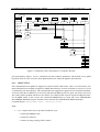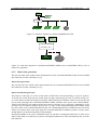
1
EUROPEAN SOUTHERN OBSERVATORY
VERY LARGE TELESCOPE
FLAMES-UVES Data Reduction Users’ Manual
VLT-MAN-ESO-19500-3016
Issue 4
Date 2007-10-12
No of Pages: 83
Prepared:
. A.
. . . . Modigliani,
. . . . . . . . . . . . . . . . .G.Mulas,
. . . . . . . . . . . .I.
. . . . Porceddu,
. . . . . . . . . . . . . .F.
. . . .Damiani
. . . . . . . . . . . . .2006-10-08
..........................
Name
Approved:
Signature
. P.
. . . . Ballester,
. . . . . . . . . . . . . . . L.
. . . . .Pasquini
......................................................................
Name
Released:
Date
Date
Signature
. M.
. . . . Peron
..........................................................................................
Name
Date
Signature
This page was intentionally left blank
This page was intentionally left blank
Issue/Rev.
0.1.0
0.3.0
0.5.0
0.5.1
0.6.1
0.8.0
1.0
2.0
3.0
4.0
Date
2002-03-15
2̃002-06-20
2̃002-08-21
2002-10-14
2002-11-12
2003-04-01
2003-07-21
2004-04-21
2004-09-30
2007-10-12
Change record
Section/Parag. affected Reason/Initiation/Documents/Remarks
all
First internal release
update
Support of June commissioning
update
Support of August commissioning
update
Support of October commissioning
update
Support of November paranalizzation
all
Support of Operations
all
Public release
update
Support of new FITS format, update
update
update
update
update
FLAMES-UVES Data Reduction Users’ Manual
VLT-MAN-ESO-19500-3016
This page was intentionally left blank
5
6
FLAMES-UVES Data Reduction Users’ Manual
VLT-MAN-ESO-19500-3016
Contents
1 Introduction
1.1 How to read this manual . . . . . . . . . . . . . . . . . . . . . . . . . . . . . . . . . . . . .
1.2 Reference documents . . . . . . . . . . . . . . . . . . . . . . . . . . . . . . . . . . . . . . .
1.3 Improvements in release 2.9.7 . . . . . . . . . . . . . . . . . . . . . . . . . . . . . . . . . .
1
1
2
2
2 Installation notes
2.1 Hardware requirements
2.2 Installation . . . . . .
2.3 Performance . . . . . .
2.4 Disclaimer . . . . . . .
3
3
3
3
4
.
.
.
.
.
.
.
.
.
.
.
.
.
.
.
.
.
.
.
.
.
.
.
.
.
.
.
.
.
.
.
.
.
.
.
.
.
.
.
.
.
.
.
.
.
.
.
.
.
.
.
.
.
.
.
.
.
.
.
.
.
.
.
.
.
.
.
.
.
.
.
.
.
.
.
.
.
.
.
.
.
.
.
.
.
.
.
.
.
.
.
.
.
.
.
.
.
.
.
.
.
.
.
.
.
.
.
.
.
.
.
.
.
.
.
.
.
.
.
.
.
.
.
.
.
.
.
.
.
.
.
.
.
.
.
.
.
.
.
.
.
.
.
.
.
.
.
.
.
.
.
.
3 Required input frames
5
4 Data reduction logical step sequence
4.1 Data reduction peculiarities . . . . . . . . . . . . . . . . . . . . . . . . . . . . . . . . . . . .
7
8
5 DRS implementation and options
9
6 Available commands
6.1 Shell script . . . . . . . . . . . . . . . .
6.1.1 flames_demo.sh . . . . . . . . . .
6.1.2 flames_popul.sh . . . . . . . . .
6.1.3 flames_steps.sh . . . . . . . . . .
6.2 Level 0 commands . . . . . . . . . . . .
6.2.1 TUTORI/FLAMES . . . . . . . .
6.2.2 DEMO/FLAMES . . . . . . . . .
6.2.3 CDROM/FLAMES . . . . . . . .
6.3 Level 1 commands . . . . . . . . . . . .
6.3.1 SPLIT/UVES . . . . . . . . . . .
6.3.2 FMTSTAB/FLAMES . . . . . . .
6.3.3 PREDICT/FLAMES . . . . . . .
6.3.4 Single fibre order table generation:
6.3.5 Master bias generation . . . . . .
6.3.6 ORFSFF/FLAMES . . . . . . . .
6.3.7 WAVECAL/FLAMES . . . . . .
6.3.8 REDUCE/FLAMES . . . . . . .
6.4 Level 2 commands . . . . . . . . . . . .
6.4.1 PREPPA/FLAMES . . . . . . . .
6.4.2 BPIMA/FLAMES . . . . . . . .
6.4.3 OFPOS/FLAMES . . . . . . . .
6.4.4 PREBKG/FLAMES . . . . . . .
6.4.5 MSFFSZ/FLAMES . . . . . . . .
. . . . . . . . . . . .
. . . . . . . . . . . .
. . . . . . . . . . . .
. . . . . . . . . . . .
. . . . . . . . . . . .
. . . . . . . . . . . .
. . . . . . . . . . . .
. . . . . . . . . . . .
. . . . . . . . . . . .
. . . . . . . . . . . .
. . . . . . . . . . . .
. . . . . . . . . . . .
ORDERPOS/UVES
. . . . . . . . . . . .
. . . . . . . . . . . .
. . . . . . . . . . . .
. . . . . . . . . . . .
. . . . . . . . . . . .
. . . . . . . . . . . .
. . . . . . . . . . . .
. . . . . . . . . . . .
. . . . . . . . . . . .
. . . . . . . . . . . .
7
.
.
.
.
.
.
.
.
.
.
.
.
.
.
.
.
.
.
.
.
.
.
.
.
.
.
.
.
.
.
.
.
.
.
.
.
.
.
.
.
.
.
.
.
.
.
.
.
.
.
.
.
.
.
.
.
.
.
.
.
.
.
.
.
.
.
.
.
.
.
.
.
.
.
.
.
.
.
.
.
.
.
.
.
.
.
.
.
.
.
.
.
.
.
.
.
.
.
.
.
.
.
.
.
.
.
.
.
.
.
.
.
.
.
.
.
.
.
.
.
.
.
.
.
.
.
.
.
.
.
.
.
.
.
.
.
.
.
.
.
.
.
.
.
.
.
.
.
.
.
.
.
.
.
.
.
.
.
.
.
.
.
.
.
.
.
.
.
.
.
.
.
.
.
.
.
.
.
.
.
.
.
.
.
.
.
.
.
.
.
.
.
.
.
.
.
.
.
.
.
.
.
.
.
.
.
.
.
.
.
.
.
.
.
.
.
.
.
.
.
.
.
.
.
.
.
.
.
.
.
.
.
.
.
.
.
.
.
.
.
.
.
.
.
.
.
.
.
.
.
.
.
.
.
.
.
.
.
.
.
.
.
.
.
.
.
.
.
.
.
.
.
.
.
.
.
.
.
.
.
.
.
.
.
.
.
.
.
.
.
.
.
.
.
.
.
.
.
.
.
.
.
.
.
.
.
.
.
.
.
.
.
.
.
.
.
.
.
.
.
.
.
.
.
.
.
.
.
.
.
.
.
.
.
.
.
.
.
.
.
.
.
.
.
.
.
.
.
.
.
.
.
.
.
.
.
.
.
.
.
.
.
.
.
.
.
.
.
13
13
13
14
15
16
16
16
18
18
19
20
21
22
23
24
26
27
31
32
33
33
35
36
8
FLAMES-UVES Data Reduction Users’ Manual
6.5
6.6
6.4.6 PREPSLIT/FLAMES . . .
6.4.7 PREPFIBRE/FLAMES . .
6.4.8 PRENORM/FLAMES . .
6.4.9 EXTRACT/FLAMES . .
6.4.10 MERGE/FLAMES . . . .
Level 3 commands . . . . . . . .
6.5.1 BKFIT/FLAMES . . . . .
6.5.2 FNDYSHIFT/FLAMES .
6.5.3 FNDRYSHIFT/FLAMES
6.5.4 XTABMERGE/FLAMES
6.5.5 XTABDUMP/FLAMES .
6.5.6 PLOT/UVES . . . . . . .
Level 4 commands . . . . . . . .
6.6.1 MODOFF/FLAMES . . .
6.6.2 FIBMSK/FILL . . . . . .
.
.
.
.
.
.
.
.
.
.
.
.
.
.
.
.
.
.
.
.
.
.
.
.
.
.
.
.
.
.
.
.
.
.
.
.
.
.
.
.
.
.
.
.
.
.
.
.
.
.
.
.
.
.
.
.
.
.
.
.
.
.
.
.
.
.
.
.
.
.
.
.
.
.
.
.
.
.
.
.
.
.
.
.
.
.
.
.
.
.
7 Session examples
7.1 Using demo-level (Level 0) commands . . . .
7.2 Using high-level (Level 1) commands . . . .
7.3 Using low-level (Level 2) commands . . . . .
7.4 Using scripts . . . . . . . . . . . . . . . . .
7.5 Data reduction chain using level-1 commands
7.6 Data reduction chain using level-2 commands
VLT-MAN-ESO-19500-3016
.
.
.
.
.
.
.
.
.
.
.
.
.
.
.
.
.
.
.
.
.
.
.
.
.
.
.
.
.
.
.
.
.
.
.
.
.
.
.
.
.
.
.
.
.
.
.
.
.
.
.
.
.
.
.
.
.
.
.
.
.
.
.
.
.
.
.
.
.
.
.
.
.
.
.
.
.
.
.
.
.
.
.
.
.
.
.
.
.
.
.
.
.
.
.
.
.
.
.
.
.
.
.
.
.
.
.
.
.
.
.
.
.
.
.
.
.
.
.
.
.
.
.
.
.
.
.
.
.
.
.
.
.
.
.
.
.
.
.
.
.
.
.
.
.
.
.
.
.
.
.
.
.
.
.
.
.
.
.
.
.
.
.
.
.
.
.
.
.
.
.
.
.
.
.
.
.
.
.
.
.
.
.
.
.
.
.
.
.
.
.
.
.
.
.
.
.
.
.
.
.
.
.
.
.
.
.
.
.
.
.
.
.
.
.
.
.
.
.
.
.
.
.
.
.
.
.
.
.
.
.
.
.
.
.
.
.
.
.
.
.
.
.
.
.
.
.
.
.
.
.
.
.
.
.
.
.
.
.
.
.
.
.
.
.
.
.
.
.
.
.
.
.
.
.
.
.
.
.
.
.
.
.
.
.
.
.
.
.
.
.
.
.
.
.
.
.
.
.
.
.
.
.
.
.
.
.
.
.
.
.
.
.
.
.
.
.
.
.
.
.
.
.
.
.
.
.
.
.
.
.
.
.
.
.
.
.
.
.
.
.
.
.
.
.
.
.
.
.
.
.
.
.
.
.
.
.
.
.
.
.
.
.
.
.
.
.
.
.
.
.
.
.
.
.
.
.
.
.
.
.
.
.
.
.
.
.
.
.
.
36
37
38
40
42
43
43
44
45
46
47
47
48
48
48
.
.
.
.
.
.
.
.
.
.
.
.
.
.
.
.
.
.
.
.
.
.
.
.
.
.
.
.
.
.
.
.
.
.
.
.
.
.
.
.
.
.
.
.
.
.
.
.
.
.
.
.
.
.
.
.
.
.
.
.
.
.
.
.
.
.
.
.
.
.
.
.
.
.
.
.
.
.
.
.
.
.
.
.
.
.
.
.
.
.
.
.
.
.
.
.
.
.
.
.
.
.
.
.
.
.
.
.
.
.
.
.
.
.
.
.
.
.
.
.
.
.
.
.
.
.
.
.
.
.
.
.
49
49
49
49
50
50
52
8 Troubleshooting
8.1 Problems in context initialization . . . . . . . . . . . .
8.2 Problem in using display with 32 bits depth computers
8.3 Problem using the scripts . . . . . . . . . . . . . . . .
8.4 PREDICT/FLAMES . . . . . . . . . . . . . . . . . .
8.5 PREPSLIT/FLAMES . . . . . . . . . . . . . . . . . .
8.6 PREPFIBRE/FLAMES . . . . . . . . . . . . . . . . .
8.7 EXTRACT/FLAMES . . . . . . . . . . . . . . . . . .
8.8 EXTRACT/FLAMES . . . . . . . . . . . . . . . . . .
8.9 Object information given on plots of merged spectra . .
.
.
.
.
.
.
.
.
.
.
.
.
.
.
.
.
.
.
.
.
.
.
.
.
.
.
.
.
.
.
.
.
.
.
.
.
.
.
.
.
.
.
.
.
.
.
.
.
.
.
.
.
.
.
.
.
.
.
.
.
.
.
.
.
.
.
.
.
.
.
.
.
.
.
.
.
.
.
.
.
.
.
.
.
.
.
.
.
.
.
.
.
.
.
.
.
.
.
.
.
.
.
.
.
.
.
.
.
.
.
.
.
.
.
.
.
.
.
.
.
.
.
.
.
.
.
.
.
.
.
.
.
.
.
.
.
.
.
.
.
.
.
.
.
.
.
.
.
.
.
.
.
.
.
.
.
.
.
.
.
.
.
.
.
.
.
.
.
.
.
.
.
.
.
.
.
.
.
.
.
.
.
.
.
.
.
.
.
.
59
59
59
60
61
62
62
63
63
65
.
.
.
.
.
.
.
.
.
.
.
.
.
.
.
.
.
.
.
.
.
.
.
.
A DRS customization
67
A.1 FLAMES-UVES pipeline data reduction parameters . . . . . . . . . . . . . . . . . . . . . . . 67
Chapter 1
Introduction
This document describes the functionality of the pipeline and Data Reduction Software (henceforth DRS) for
data obtained using the FLAMES/UVES facility at the ESO VLT Kueyen telescope. Updated informations
and releases of the present documentation can be obtained at the following URL: http://www.eso.org/pipelines
. Additional information is provided by the correspondent Quality Control pages that can be found at the following URL: http://www.eso.org/observing/dfo/quality/ . Users can submit problem reports either by issuing
a software problem report (using the tool accessible internally to Paranal and Garching Operations) or by
sending an e-mail to [email protected] or to [email protected]. The pipeline to reduce FLAMES-UVES data
has been developed as an extention of the UVES pipeline. This last is described in [1]. Users not familiar with
the UVES pipeline should read [1].
A VLT pipeline is a subsystem of the Data Flow System (DFS) with the task to do automatic data reduction
of calibration and science frames. It is used by Paranal Science Operations (PSO) to automatically (on-line)
reduce frames and thus have a quick-look at the data to assess the health of the instrument and the quality
of calibrations and observations and decide on real time if an observation needs to be repeated. Moreover
Garching Data Flow Operations (DFO) uses it off-line to perform more detailed quality control and instrument
trending, preparing master calibrations and reducing science observations for service mode observations.
A set of optical fibres (up to 8 at a time) brings the light collected on the focal plane to the UVES (UltravioletVisual Echelle Spectrometer) spectrograph. The fibres can be positioned on the focal plane as the observer
chooses, using the FLAMES fibre positioner (for more information on the FLAMES VLT facility, please see
[4]).
Every observation performed with this powerful instrument contain a very rich amount of information, that
needs a specialized software such as this DRS to be extracted properly, even when not all fibres are actually being used. The DRS has been designed to work well within known hardware constraints, such as the
instrument mechanical stability limits, or availability of calibration data. The reliability and accuracy of the
data reduction procedure do indeed depend sensitively on the “goodness" of the calibration data used in the
reduction. Although the DRS has been designed to be flexible with respect to small mismatches between
calibration and science data, the best results will be obtained using calibrations that are taken as “close”
as possible to the science observations. Here “close” does not mean necessarily “close in time” but more
“under the same ambient conditions”. In fact, it is now known that the apparent placement of fibres on
the UVES detector changes according to local temperature and pressure, and of course after instrument setup
changes.
1.1 How to read this manual
This manual is addressed to users who likes to reduce FLAMES-UVES data at their home institutes. If
the user prefers not to follow the order proposed we suggest to read chapter 2 to know how to install the
software and be advised about what are the present hardware and software requirements. Chapter 3 lists all
the data necessary to reduce a FLAMES-UVES science. Next we suggest the user, after having read chapter
4 to have an overview of the data reduction sequence, to try practical examples as described in chapter 7.
1
2
FLAMES-UVES Data Reduction Users’ Manual
VLT-MAN-ESO-19500-3016
These examples run FLAMES-UVES and UVES context commands which are summarized in chapter 5 and
described in detail in chapter 6 and on the on-line help. The last three mentioned chapter and the on line help
should be the most useful to consult also for users who have got some practice of the commands. In case
of problems we have included also a troubleshooting section (see chapter 8). Finally for users very expert in
this software usage, appendix A gives a description of any MIDAS keyword used as parameter default for the
provided data reduction commands. Our advice to the user is not to change such defaults, but instead properly
choose command parameter values.
1.2 Reference documents
[1]
[2]
[3]
[4]
[5]
UVES Pipeline User’s Manual
VLT-MAN-ESO-19500-2964
http://www.eso.org/pipelines
FLAMES-UVES Data Reduction Software Design and Architecture Report
VLT-TRE-ITA-13750-0002
http://www.eso.org/org/dmd/DFS-related-papers.html
Automatic data reduction in support of the FLAMES-UVES VLT facility
Proceedings of the SPIE, Volume 4844, pp. 310-320 (2002).
http://www.eso.org/org/dmd/DFS-related-papers.html
FLAMES User Manual
VLT-MAN-ESO-13700-2994
www.eso.org/instruments/flames/manuals.html
The FLAMES-UVES Pipeline
The ESO Messenger, 118, 8.
1.3 Improvements in release 2.9.7
• We include a more accurate ThAr reference line catalog.
• Some compilation warning have been fixed to improve portability.
Chapter 2
Installation notes
2.1 Hardware requirements
We suggest to have at least 512 MB RAM and 40 GB HD. The DRS will still run on systems with less RAM,
but much more slowly. In this case, we recommend to have the (main) swap partition on a physically different
disk with respect to the one containing the input and/or output data, to minimise disk thrashing. In particular
in case of I/O bound systems we suggest to have input raw data on a physically different disk with respect to
the one on which one runs the process.
A complete data reduction using the scripts produces about 2 GBytes of data.
2.2 Installation
We assume that the user has defined the environment variables MIDASHOME and MIDVERS, and that the
MIDAS release is 07SEPpl1.1. The user will get a file called fluves_cdrom_2.9.7.tar.gz. This can be installed
as follows. If rel_dir is the installation directory:
• mv fluves_cdrom_2.9.7.tar.gz rel_dir
• cd rel_dir
• gunzip fluves_cdrom_2.9.7.tar.gz
• tar xvf fluves_cdrom_2.9.7.tar
• cd fluves
• ./setup.sh
• follow the instructions displayed at the end of the installation
2.3 Performance
According to our test beds, on Linux OS based systems our data reduction software performs better than on
other proprietary OS. A factor 2.2 difference has been measured between running the script flames_popul.sh
on a PC (2 AMD 1.800 CPUs, 2 GB RAM, GNU/Linux OS, ReiserFs filesystem) and an HP J5600 with 1GB
RAM HP-UX OS, and a standard DFS installation (MAR2003/dfs-4_7). The Sun-Solaris 5.8 platform is a
factor 2.6 slower than the PC-Linux.
3
4
FLAMES-UVES Data Reduction Users’ Manual
VLT-MAN-ESO-19500-3016
2.4 Disclaimer
This release has been tested on Intel-Linux Scientific Linux 40, Intel centrino Linux Fedora 6, Sun-Solaris
5.8 systems. We cannot guarantee on other systems. In particular we are aware that some FLAMES-UVES
commands are failing on an Digital Alpha (64 bit architecture) Linux (Suse 7.1) platform, and on AMD (64
bit architecture) Linux (Suse 10.2).
Chapter 3
Required input frames
The following calibration data are needed by the DRS to correctly reduce your science exposures:
• Format-check frames
• Bias frames (optional)
• Single Fibre Order definition frames
• Slit flat-field frames
• Fibre flat-field frames: odd, even, all fibres
• Fibre wavelength-calibration frames
The DRS will not work if any of these data is missing. The only possible exception to this statement is the
Format-check frame(s), which is strictly needed for automatic, unattended data reduction. For interactive data
reduction, Order definition frames (see below) can substitute them, with some user intervention (wavelength
calibration without formatcheck frames is interactive).
Dark frames are usually not provided. DFO usually measures the Dark count level and provide this as a
number to be subtracted during data reduction. Moreover we assume one has available an appropriate arc
lamp line reference table. This table is provided as part of the CDROM distribution under the directory
fluves/calib with filename thargood_3.tfits. This table has been improved with respect to the previous one,
thargood_2.tfits which we still provide in the CDROM release.
Calibration frames consist of bias, flat-field frames, and wavelength-calibration frames. Peculiar of this data
reduction is instead the need by the DRS of different types of flat-fields, some of which are taken through the
fibres (using the OzPoz calibration unit), and some using the UVES slit (using the UVES calibration unit).
Moreover, as in the UVES pipeline, the proper support of data in FIBRE mode foresees the use of special
Format-check frames, this time taken illuminating the simultaneous calibration fibre only.
The Format-check frame has a key role for automatic, non-interactive data reduction; its comparison with a
physical model of the instrument provides a first-order approximation for the order/fibre trace positions and a
first-order approximation of the wavelength calibration relation.
While the first-order approximation of the order-fibre positions could be derived from an order definition
frame, wavelength calibration without a Format-check frame would necessarily involve the interactive identification of a few lines of the Th-Ar lamp, making fully automatic data reduction impossible.
The slit flat-fields are used to eliminate pixel-to-pixel effects. The fibre flat-fields serve instead to locate the
fibre positions, both relative to one another and absolute, within some tolerance; to know the cross-sectional
profile of each fibre at each wavelength; and to determine the relative throughput of different fibres. These
fibre flat-fields are only usable if the fibre traces fall in regions illuminated in at least one of the slit flat-fields;
fibres whose light falls, even in part, in dark regions of the slit flat-fields are discarded. The DRS considers as
really flat only a subregion of each slit flat field discarding a few pixels at the flat field border.
To properly evaluate the background level and avoid overlapping of orders, each slit flat field has to be taken
with a limited slit aperture. To cover all the fibres (allowing also for some variability in their placement)
5
6
FLAMES-UVES Data Reduction Users’ Manual
VLT-MAN-ESO-19500-3016
several slit flat fields are thus necessary, taken with different offsets with respect to a central position and
overlapping between each other.
The wavelength calibration frames must be taken through the same set of fibres as the science frame.
The fibres’ images on the detector are so closely packed that the cross-sectional profiles of adjacent fibres
overlap to some non-negligible extent. Therefore, a single flat-field frame, would not yield enough information
on individual fibres to perform a correct data reduction. Instead, the DRS requires fibre flat-fields on which
the fibres can be clearly separated, such as one containing only odd-numbered fibres and another containing
only even-numbered fibres.
The order definition frame, if taken with the simultaneous fibre, could also be used as an additional flatfield frame covering the simultaneous calibration fibre. Such inclusion is necessary to be able to extract the
simultaneous calibration fibre. In such a case one would add it in the pool of odd-even fibre flat fields (see
below), and this set of frames would thus contain completely separable images of all fibres.
In addition to the above, an all-fibre flat-field is needed to correct for relative throughput differences between
odd and even fibres. This can be replaced by a Nasmyth screen all-fibre flat-field for higher accuracy.
If it is planned to observe using the simultaneous calibration fibre, it is also necessary to have in the calibration
data a ThAr frame with the ThAr lamp feeding all the same fibres used during the night (7OzPoz+1SimCal)
as well as an all fibre flat-field with the flat-field lamp feeding all the same fibres used during the night
(7OzPoz+1SimCal). This is the minimum fibre flat-field set usable by the DRS.
We would like to emphasize the importance of having “proper” calibration data to be able to reduce the science
observations with best quality. For example, if because of thermal shifts the available slit flat-fields do not
cover the position where a (science-frame) fibre is located, this fibre will be discarded and its data is unusable.
The same is true if fibre positions in the science-frame are shifted too much with respect to the corresponding
positions of the fibre flat-field frames used to do the data reduction. This may occur in case of automatic on
line pipeline data reduction on Paranal where usually the calibration data base is updated with a one month
time scale. Moreover, the cross-sectional profiles of the fibres may change e. g. due to slightly different
focusing. Since this, in turn, changes the contamination between adjacent fibres, a significantly different
profile between calibrations and science data will lead to an incorrect deconvolution of the fibres. This release
searches for possible instrument shifts along Y (i. e. perpendicular to dispersion) in the interval [-6,6] pixel.
It satisfactorily reduced commissioning data which, due a still not completely stable instrument setup, were
characterized by shifts between the science observation and the calibration in the range [-3.5,3.5]. It must be
said that the source of such Y shift was discovered and fixed during an instrument software upgrade occurred
before the beginning of FLAMES operations and so we do not expect the user will receive data affected by
shifts between science and calibrations of more than one pixel. This release allows to interactively recover
extraction also in cases of wider shifts (see command REDUCE/FLAMES at page 27).
The FLAMES positioner uses two plates and two distinct sets of fibres, with two distinct entrance positions
in UVES.
A simultaneous calibration fibre for precise radial velocity measurements is also available. Using this fibre the
spectral format changes, including (at most) 7 OzPoz fibres and 1 SimCal fibre. Therefore, all calibration data
need to be taken with the same FLAMES plate and (≤ 8 OzPoz fibres)/(≤ 7 OzPoz fibres+1 SimCal fibre)
configuration as the actual science frames to be reduced.
Although we introduced means to detect and appropriately treat saturated pixels in the data reduction, it might
happen that a saturated frame affects the data reduction. More specifically, while isolated saturated pixels can
be easily detected by the DRS and excluded from the subsequent data reduction, strongly saturated emission
lines can produce a very irregular distribution of scattered light on the frame, causing a poor background
subtraction and, as a consequence, wrong results in the determination of shifts to be applied to each fibre
(correlation step). In particularly pathological cases, this may lead to a failure of the automatic data reduction
procedure, and require manual intervention to properly extract the data.
Chapter 4
Data reduction logical step sequence
Here we outline the logical sequence of steps which are needed to perform a complete spectral extraction
of FLAMES/UVES data. All these operations can be carried out using commands in the FLAMES context.
Initially all FITS frames need to be splitted using the command SPLIT/UVES to convert them into MIDAS
format, properly orient and classify them. Examples of data reduction are in chapter 7.
1. For most frames (fibre and slit flat-fields, science frames) a variance frame and a bad-pixel mask must
be created.
2. First, a so-called format-check frame is examined. This frame must have been taken with a single fibre
illuminated by a (Th-Ar) wavelength-calibration lamp, and all other fibres dark. This frame is compared
with a physical model of the CCD illumination, with the help of an appropriate table of lines emitted
by the calibration lamp, to derive a first guess of the order positions and of the wavelength-calibration
solution.
3. The whole set of fibres is considered (or at least those used in the science exposure), by processing
both an odd-numbered- and an even-numbered fibre flat-field frames. In this way a complete (raw)
fibre-order position table is obtained.
4. From the latter, the inter-order (background) table is computed, for later computation and subtraction
of scattered-light contamination.
5. Slit flat-field frames are processed. At least two half-slit flat-fields are needed to cover the fibreilluminated region without overlapping, and these are combined and normalized. They will be used
to remove pixel-to-pixel effects later. Associated variance frames and bad-pixel masks are also created.
6. odd/even fibre flat-fields are processed. These frames contain the required information on the fibre
cross-dispersion profile, and need to be input as separate odd/even fibre frames since adjacent fibres
have partially overlapping profiles. Fibres for which there is no corresponding slit-flat-field information
are ignored. The frames are corrected for background light, and associated variance frames and badpixel masks are created.
7. The algorithm requires also an all-fibre flat-field frame, to compute the relative throughput among the
odd and even fibres. It is treated as if it were a science frame, with the same extraction procedure, to
obtain for each fibre and order a wavelength-dependent normalization (instead of a spectrum). Since
the FLAMES context includes two extraction methods (standard and optimal), the same choice is possible to extract the fibre normalizations here. Moreover, the all-fibre flat-field frame is also used as a
reference for the positions of all fibres, since they are simultaneously lit here. For this purpose, the
cross-dispersion shifts between the fibre positions in the odd and even fibre flat-field frames are computed with this common reference, and this additional information is stored in the order-fibre table.
8. Wavelength calibration is done, using a fibre frame with each fibre illuminated by a ThAr lamp, the
guess line and fibre-order tables determined from previous data reduction steps. This step extracts each
fibre spectrum, looks for ThAr lines and identifies them with help of a guess solution.
7
8
FLAMES-UVES Data Reduction Users’ Manual
VLT-MAN-ESO-19500-3016
9. Eventually, the science spectra are extracted, either using standard or optimal extraction. Because of
UVES stability limitations, there may be shifts between the fibre images in the flat-fields and in the
science frames. These shifts are expected to occur in the cross-dispersion direction and to be at most
±1 pixel. Since especially optimal extraction is extremely sensitive to such shifts (spectra with large
S/N cannot be extracted satisfactorily for shifts larger than 0.1 pix), the extraction routine computes
the value of the shift (using a correlation-function method), and applies the opposite shift to the fibre
flat-fields (that’s why pixel-to-pixel effects need to be computed separately using slit flat-fields). After
doing that, the optimal extraction is performed using the fibre flat-fields as a model to fit the science
frame at every wavelength (the fit amplitudes are the extracted spectra at each wavelength), using at
the same time the fibre profile information to deconvolve the partial fibre overlap. Standard extraction
is somewhat simpler, doing only a sum of the science frame fibre spectra over a pre-defined window
across dispersion, without fitting, but including also a deconvolution of fibre cross-contamination.
10. Next, extracted spectra are wavelength-calibrated.
11. Last, wavelength-calibrated, merged spectra are created.
4.1 Data reduction peculiarities
The data reduction software design to reduce FLAMES-UVES fibre-echelle mode data (described in [2], [3]
and [5]) has some data reduction peculiarities for example with respect to the standard echelle data reduction,
or with respect to the extraction of fibre spectra designed for FEROS.
With respect to a standard echelle package:
• The fibre flat field spectra are used as "true" physical model of the light distribution on the detector in
the optimal extraction, instead of some analytic approximation (e.g. as in UVES-echelle mode where a
Gaussian+constant function distribution is used).
• A very good solution of the adjacent fibre contamination (which is a peculiar problem of fibre-fed multiobject spectrographs with close packed fibres and thus does not occur in echelle mode) is achieved.
• Error propagation is throughly performed from beginning to the end of the data reduction obtaining
analytical pixel-to-pixel variances.
• Spectra corresponding to different fibres, having a different fibre throughput, are corrected giving reliable relative fibre throughputs.
• Thanks to the use of three different kind of flat-field spectra (single fibre, odd-even-all fibres, slit flat
fields) usually the final merged spectra have a very high quality, in which any residual oscillation artifacts (still present in some high S/N UVES echelle extracted spectra) are well below the noise level.
With respect to FEROS we have the same difference as before with an additional one:
• In FEROS the flat fielding is done on the extracted spectra, extracting before the science and the flat
field and dividing the first by the latter. Although this procedure has empirically been shown to lead
to negligible differences with respect to the "correct" one, we still use the "correct" one (first correct
science by flat field, next extract the spectra).
The adopted data reduction together with to the mentioned pros implies a number of contra. Essentially we
have two. We need many calibrations, for example comparing, many more than, for example, UVES operated
in echelle mode.
The achieved very good extraction quality is paid with a quite intensive computational cost. On Paranal the
hardware dedicated to data reduction in support of FLAMES-UVES changed from the probably more reliable
(and expensive) HP-UX architecture to the faster PC-Linux architecture. To improve even more computational
performance we had to define additional simplified (and with lower quality products) data reduction modes
(“fast” and “quick”) just in support of operations even if at the moment they are not used.
Chapter 5
DRS implementation and options
The DRS is implemented as a set of MIDAS commands, included in a new MIDAS context called FLAMES
(Table 5.3). The FLAMES context needs, and thus automatically loads, the UVES one. The FLAMES context
commands can be run individually (Level 2 commands), or called in sequence by other commands (Level 1
commands). Even higher-level commands (Level 0) are included, such as a tutorial. The pipeline uses level 1
commands.
The UVES pipeline command SPLIT/UVES has been updated to support also FLAMES-UVES data reduction. This command splits and re-orient the images contained in the input FITS file and additionally classify
them creating and assigning a proper value to the MIDAS file descriptor DO_CLASSIFICATION. Level 1
commands expect that all input data, listed in an input catalogue, are identified by the value of their descriptor
DO_CLASSIFICATION. Input catalogs of Level 2 commands instead recognize data by the value of their
MIDAS descriptor IDENT.
In Table 5.1 we list the category Data Products (DPR) keywords for the currently supported data.
Frame Type
Science in OzPoz mode
Science in SimCal mode
Bias
Dark
Nasmyth Screen FF
Wavelength calibration
Wavelength calibration
Odd FF
Even FF
All FF
Odd FF
Even FF
All FF
Formatcheck
Order Trace
Slit Flat Fields
TYPE
CATG
TECH
Science frames
OBJECT,OzPoz
SCIENCE
MOS
OBJECT,SimCal
SCIENCE
MOS
Calibration fibre fed frames
BIAS
CALIB
IMAGE
DARK
CALIB
IMAGE
LAMP,FLAT,NASMYTH
CALIB
MOS
LAMP,WAVE,OzPoz
CALIB
MOS
LAMP,WAVE,SimCal
CALIB
MOS
LAMP,FLAT,ODD,OzPoz
CALIB
MOS
LAMP,FLAT,EVEN,OzPoz
CALIB
MOS
LAMP,FLAT,ALL,OzPoz
CALIB
MOS
LAMP,FLAT,ODD,SimCal
CALIB
MOS
LAMP,FLAT,EVEN,SimCal CALIB
MOS
LAMP,FLAT,ALL,SimCal
CALIB
MOS
LAMP,FMTCHK,SimCal
CALIB
MOS
LAMP,ORDERDEF,SimCal CALIB
MOS
Special frames in echelle mode
LAMP,SFLAT
CALIB
ECHELLE
Note
8 OzPoz fibres
7 OzPoz, 1 SimCal
Same as UVES
Same as UVES
Nasmyth Screen
8 OzPoz fed by ThAr
7 OzPoz, 1 SimCal fed by ThAr
Odd Fiber FF, 4 OzPoz
Even Fiber FF, 4 OzPoz
All Fiber FF, 8 OzPoz
Odd fibre FF, 4 OzPoz
Even Fiber FF, 4 OzPoz
All Fiber FF, 7 OzPoz
1 SimCal fed by ThAr
1 SimCal fed by Flat
3 sets of 3 slit FF each
each set taken at diff Y pos
Table 5.1: Required DPR keywords
The plate No. is identified through the keyword ESO.INS.OBSPLATE. Plate No. 1 corresponds to a keyword
value equal to 1. Plate No. 2 corresponds to a keyword value equal to 2.
The keyword ESO.OCS.SIMCAL will be used to associate the proper master calibration frame to the input
raw frame separating the cases in which the simultaneous calibration fibre is involved (value equal to 1) or not
(value equal to 0).
When an accuracy better than 2% is required for the absolute fluxes, one should take flat fields using the
Nasmyth screen and “attached templates”.
In Table 5.2 we list the DO_CLASSIFICATION values for the currently supported data.
9
10
FLAMES-UVES Data Reduction Users’ Manual
VLT-MAN-ESO-19500-3016
Frame Type
DO_CLASSIFICATION
Raw Frames
ThAr line reference table
LINE_REFER_TABLE
Formatcheck frame
FMTCHK_x
Reference Formatcheck frame
ARC_LAMP_FORM_x
Single Order trace frame
FIB_ORDEF_x
Bias
BIAS_x
Master Bias
MASTER_x
Dark
DARK_x
Slit Flat Field
SFLAT_x
Nasmyth Screen Flat Field
FIB_FF_NASMYTH_x
Wavelength Calibration frame
FIB_ARC_LAMP_x
Odd Flat Field
FIB_FF_ODD_x
Even Flat Field
FIB_FF_EVEN_x
All Flat Field
FIB_FF_ALL_x
Science OzPoz
FIB_SCI_x
Science SimCal
FIB_SCI_SIM_x
Science COMBINED
FIB_SCI_COM_x
Data Products
MASTER Slit Flat Field
MASTER_SFLAT_x
DRS Setup Table
FIB_DRS_x
Guess Order Table
FIB_ORD_GUE_x
Guess Line Table
FIB_LIN_GUE_x
Background Table
FIB_BKG_x
Order-Fibre Table
FIB_ORDEF_TABLE_x
Line-Fibre Table
FIB_LINE_TABLE_x
Fibre data* frames
FIB_FF_D0n_x
Fibre common frames
FIB_FF_COM_x
Fibre norm frames
FIB_FF_NOR_x
Fibre nsigma frames
FIB_FF_NSIGMA_x
Fibre sigma frames
FIB_FF_S0n_x
Fibre badpixel frames
FIB_FF_BPn_x
Slit FF data frames
SLIT_FF_D0n_x
Slit FF common frames
SLIT_FF_COM_x
Slit FF norm frames
SLIT_FF_NOR_x
Slit FF sigma frames
SLIT_FF_S0n_x
Slit FF badpixel frames
SLIT_FF_BPn_x
Slit FF bound frames
SLIT_FF_BNDn_x
Table 5.2: List of frame types and corresponding values of the MIDAS descriptor DO_CLASSIFICATION
assigned by the command SPLIT/UVES. ∗ Note: x= REDL or REDU; n=1,2,..nflats where in case of slit flat
fields NFLATS is a DRS keyword indicating the (automatically determined) minimum number of equalized
flat fields which are necessary to cover the total Y span, while in case of the fibre flat fields it indicates the
number of basic (uncontaminated) fibre flat fields, typically (but not necessarily) 2 (odd/even).
Level 2 commands provide more finely grained control over all phases of the data reduction, and hence may
be used to fine tune all the parameters, tailoring them on specific data. Exploiting this requires, of course, a
detailed understanding of the algorithms internally used by the DRS and the exact sequence of data reduction.
To ease data reduction, the user may also benefit from the shell script, flames_demo.sh.
Similarly we include in section 7.1 an example procedure demonstrating how to create a catalogue with all the
data needed for a complete data reduction using the command DEMO/FLAMES. The script flames_demo.sh
and the command DEMO/FLAMES do data reduction assuming default setting for the data reduction parameters. This defaults usually provides robust and good quality data reduction but in some cases may not be the
best solutions for the user’s case.
If the user would like to do interactive data reduction, e.g. trying the effect of changing some data reduction
parameters, s/he could use Level 1 or Level 2 commands. Level 1 commands are the one called in automatic
data reduction by the pipeline. Those are the ones which contain most of the few changes in parameter setting
done to make the pipeline more robusts to support operations. Level 2 commands have been left as much
as possible unchanged to allow the experience user to get cutomize (at its own risk) his data reduction. An
example showing how to use Level 1 commands in a data reduction chain is also given in section 7.5. An
example showing how to use Level 2 commands in a data reduction chain is also given in section 7.6.
The data reduction can be performed in two ways. One may choose between “optimal” or “standard” ex-
FLAMES-UVES Data Reduction Users’ Manual
VLT-MAN-ESO-19500-3016
11
traction methods, which differ essentially in the weights assigned to the pixel data across a fibre at each
wavelength. Moreover, the Optimal extraction iteratively applies a kappa-sigma clipping of bad pixels, while
the Standard extraction works in one straight iteration. Due to these reasons, the Optimal extraction yields
to the best signal-to-noise ratio, especially for under exposed spectra, as it attempts to make full use of all
the information contained in the science frame; on the other hand, it can be more sensitive to uncorrected
mismatches between science and calibration data, and it is computationally much more intensive. Standard
extraction does not use weights, but a user-defined window size, which can be restricted to the fibre core if
mismatches between science and calibration data are found; it is therefore more robust, at the price of a reduced sensitivity. Both methods include a deconvolution of adjacent fibre cross-contamination. To improve
performance, in support of PSO, we have added to the normal (and accurate) data reduction mode also a so
called quick & dirty data reduction (which doesn’t need slit flat fields and does not correct for possible fibre
shifts between observations and calibrations), and and intermediate mode, the so called “fast” one, (which
still needs the slit flat fields but does not correct for possible instrument shifts between observations and
calibrations). Each mode support “optimal” and “standard” extraction.
In addition the command SPLIT/UVES from the UVES context has been upgraded to support FLAMES data
reduction and is supposed to be run as first command to properly split and orientate input raw frames and
classify them.
12
FLAMES-UVES Data Reduction Users’ Manual
VLT-MAN-ESO-19500-3016
Level 0 commands: commands needed to test the reduction pipeline
TUTORI/FLAMES
(none)
DEMO/FLAMES
in_cat [method] [filter_switch] [saturation_threshold]
CDROM/FLAMES
in_cat [method] [filter_switch] [saturation_threshold]
STEPS/FLAMES
in_cat [method] [filter_switch] [saturation_threshold]
Level 1 commands: main commands for pipeline data reduction
SPLIT/UVES
input [catalog] [trim]
PREDICT/FLAMES
format_check_frame [out_cat] line_table [xy_mbox] [xy_trans] [angle]
FMTSTAB/FLAMES
format_check_frame [out_cat] ref_cat [xy_mbox] [xy_trans] [angle]
MASFLAT/FLAMES
in_cat out_cat ref_cat [bias_meth] [dark_meth] [bkg_meth]
MASTER/FLAMES
in_cat out_cat ref_cat [bias_meth] [dark_meth] [bkg_meth]
ORFSFF/FLAMES
in_cat out_cat ref_cat [method] [bias_val] [filter_sw]
[saturation_threshold] [sff_fibff,drs_cubify]
WAVECAL/FLAMES
in_cat out_cat ref_cat [mode] [resol] [fits] [precision]
REDUCE/FLAMES
in_science_cat out_science_cat ref_cat [extract] [bias_val]
[filter_sw] [saturation_threshold] [drs_sci_cubify,drs_cubify]
Level 2 commands: step-by-step reduction commands
PREPPA/FLAMES
frame_cat [bad_pix_mask] [filter_switch] [x_width,y_width] [n_iterations]
[kappa_sigma_thres] [apply_cuts_switch] [low_cut,high_cut]
BPIMA/FLAMES
template_ima [out_bad_pix_ima] [cut_levels]
OFPOS/FLAMES
[guess_order_table],[order_fibre_table],[in_fibre_cat],[max_extend]
[nb_traces] [widthi] [hough_trans_switches] [thresi]
[x_degree,ord_degree] [hot_thres,step]
[cluster,slope_min,slope_max,step_slope,step_orig]
PREBKG/FLAMES
order_table back_table [n_windows] [x_width_max,y_width_max]
MSFFSZ/FLAMES
in_slit_ff_frame [order_fibre_table]
PREPSLIT/FLAMES
in_slit_cat order_fibre_table out_slit_cat out_slit_name
PREPFIBRE/FLAMES
in_fibre_cat,(slit_ff_cat) back_table order_fibre_table
[threshold] out_fibre_cat out_fibre_name [method]
PRENORM/FLAMES
all_fibre_ff_frame fibre_ff_cat,(slit_ff_cat) back_table,in_order_fibre_table
out_order_fibre_table [threshold] [method] [max_shift]/[window_size]
EXTRACT/FLAMES
science_frame fibre_ff_cat,(slit_ff_cat) back_table,order_fibre_table
[out_spectra] [threshold] [method] [max_shift]/[window_size] [correl_pars]
MERGE/FLAMES
in_spectrum rebin_base_name merge_base_name
Level 3 commands: useful commands (plotting/quality check commands)
BKFIT/FLAMES
in_ima order_fibre_table back_table [kappa_sigma_thres] out_back_ima
FNDYSHIFT/FLAMES
input_frame fibre_cat slit_cat order_table [max_shift]
FNDRYSHIFT/FLAMES input_frame fibre_cat slit_cat order_table [max_shift]
PLOT/UVES
fname [xrange] [yrange] [title] [hcopy] [fibre_drs_id]
Level 4 commands: administration/extra commands
MODOFF/FLAMES
formatcheck_frame
FIBMSK/FILL
input_frame
Table 5.3: Commands in the FLAMES context
Chapter 6
Available commands
This section describes all commands in the FLAMES context, and the sequence in which they need to be
invoked in order to perform a complete spectral extraction. The FLAMES context inherits some features
already present in the UVES context, but includes many others that are new, designed ad hoc for the fibre-fed
spectrograph case. One may also run the following scripts instead of the full sequence of MIDAS commands.
The context can be customized modifying the global keywords set in the procedure
$PIPE_HOME/uves/flames/pipe/proc/flames_def_drs_par.prg. Many of the commands use as default parameter setting the values specified by the MIDAS keywords defined in that procedure. Another possibility is to
give appropriate values in an interactive data reduction section (See Appendix A.1). We suggest the latter to
the user. The parameter defaults has been chosen to insure robust and good quality data reduction. We suggest
the user to use level 1 commands.
6.1 Shell script
In the $PIPE_HOME/uves/flames/scripts directory, in addition to the scripts described in detail in the following paragraph, a number of executable files are also given , most of them called flames_”reduction_step”,
where “reduction_step” is the name of the data reduction step to be performed. These can be used as templates
to do your actual data reduction. It is important to notice that:
• the provided path+shell_script or path+input_frame must exist
• if one runs the shell_scripts using an executable file or creates one putting a command or a file per line,
using a \ as line terminator, this \ must be the last character of the line in that file, as in the provided
templates. The last line of the file should not terminate with a \.
6.1.1 flames_demo.sh
This script can be used to do a complete data reduction using defaults for data reduction parameters.
Syntax:
$PIPE_HOME/uves/flames/scripts/flames_demo.sh frame_list
Input:
• frame_list: ASCII list of a complete data reduction set, i.e. a set of FITS files comprising:
– a Th-Ar line reference table
– a raw Format-check frame
– a raw Order-definition frame
– Raw Bias frames (usually 5 frames)
– raw Slit flat-field frames (usually 3 sets of 3 frames each)
13
14
FLAMES-UVES Data Reduction Users’ Manual
Formatcheck
Frame
Single Fibre Order Definition
Frame
Line Refer.
Table
VLT-MAN-ESO-19500-3016
Odd−Even−All
Frame
ThAr all fibre
Frame
flames_popul.sh
Slit Flat Field(s)
Line Table
(Guess)
Order Table
(Guess)
Background
Table
DRS setup
Table
Order Fibre
Table
FibreFF*
Biases
Science
Line Fibre
Table
SlitFF*
Reference
Formatcheck
Extracted
Science
Wavecal
Science
Merged
Science
Figure 6.1: Data flow diagram for script flames_demo.sh.
– raw Fibre flat-field frames: odd, even, all fibres (3 frames)
– a raw Wavelength-calibration frame
– a raw Science frame
Output:
• Guess line and order tables, DRS setup table (Format-check step, if order-definition frame is provided
the order table is refined).
• all frames (except order-definition and format-check) receive an associated fake bad-pixel mask and a
variance (sigma) frame.
• raw order-fibre table, order-fibre table, slit flat-field (slitff*), and fibre flat-field (fibreff*) frames.
• line tables.
• for each fibre: extracted, bias- and background-subtracted, flat-fielded science spectrum, rebinned science spectrum, merged science spectrum.
We think that this script, should be the easiest one to use for a complete data reduction with default parameters. Its output will be placed in the directory $HOME/midwork/tmpwrk/. This script uses the command
DEMO/FLAMES. As described below this command also has some parameters with default values. If the
user wants to do a slightly different data reduction, s/he may refer to the provided example and eventually
customize it to his/her needs.
6.1.2 flames_popul.sh
This script prepares a complete set of calibration frames to be used to reduce a science frame.
Syntax:
$PIPE_HOME/uves/flames/scripts/flames_popul.sh frame_list
Input:
• frame_list: ASCII list of a complete data reduction set, i.e. a set of FITS files as listed for the script
flames_demo.sh (except for the science raw frame which is not necessary in this case).
FLAMES-UVES Data Reduction Users’ Manual
Formatcheck
Frame
VLT-MAN-ESO-19500-3016
Single Fibre Order Definition
Frame
Line Refer.
Table
15
Odd−Even−All
Frame
ThAr all fibre
Frame
flames_popul.sh
Slit Flat Field(s)
Line Table
(Guess)
Order Table
(Guess)
Background
Table
Biases
DRS setup
Table
Order Fibre
Table
FibreFF*
Line Fibre
Table
SlitFF*
Reference
Formatcheck
Figure 6.2: Data flow diagram for script flames_popul.sh.
Output:
• Guess line and order tables, DRS setup table (Format-check step, if order-definition frame is provided
the order table is refined).
• all frames (except order-definition and format-check) receive an associated fake bad-pixel mask and a
variance (sigma) frame.
• raw order-fibre table, order-fibre table, slit flat-field (slitff*), and fibre flat-field (fibreff*) frames.
• line tables.
• for each fibre: extracted, bias- and background-corrected, flat-fielded science spectrum, rebinned science spectrum, merged science spectrum.
We think that this command should be the easiest one to use to generate a complete data base. Its output will be placed in the directory $HOME/midwork/tmpwrk/, and the generated data base in the directory
$HOME/midwork/tmpwrk/data/ .
6.1.3 flames_steps.sh
This script can be used to do or repeat some particular step of data reduction.
Sintax:
$PIPE_HOME/uves/flames/scripts/flames_steps.sh frame_list <num>
Input:
• frame_list: ASCII list of the FITS files required for the data reduction one is interested in. The
input depends by < num >
– 0: Input is: a full list of raw data as for for flames_demo.sh
– 1: Input is: a formatcheck raw frame and a reference ThAr table. Additionally, if available, a not
necessary input are also 2 splitted reference slit formatcheck frames for that setting. The CDROM
contains them for each UVES wavelength setting in directory fluves/calib and have prefix mfc.
– 2: Input are a list of bias frames (usually 5).
– 3: Input are: 3 sets of 3 slit flat field each set. Two master biases, one for each chip, two drs setup
tables, one for each chip.
– 4: Input are: Raw data (Odd, even, all flat fields, a single fibre flat field, slit flat fields) and
calibration data (guess order and DRS setup tables, master biases).
16
FLAMES-UVES Data Reduction Users’ Manual
VLT-MAN-ESO-19500-3016
– 5: Input are: ThAr raw frame. DRS setup tables, guess line tables, order-fibre tables. Be careful
to use input order-fibre table file names up 8 char max without extention (e.g. longname.tfits).
– 6: Input are: science frame. slitff* and fibreff* frames, master biases, order-fibre tables, line-fibre
tables.
• < num >: an optional number (0-6) indicating which data reduction step one would like to perform
according to the following schema:
– none: it this case it is assumed as it would be given 0.
– 0: a complete data reduction comprising step 1-6.
– 1: formatcheck step. Generation of guess order table used in 4, and guess line table used in 5.
– 2: Master bias generation used in 3, 4, 6.
– 3: Master slit flat field generation.
– 4: Master slit flat field preparation and fiber-order table generation (used in 5, 6) and slitff*.fits,
fibreff*.fits frames preparation (used in 6).
– 5: wavelength calibration (used in 6).
– 6: science reduction.
This script works similarly to the other (flames_demo.sh) except for the fact that while flames_demo.sh uses
directly level 2 commands, flames_steps.sh uses level 1 commands. Moreover this script also allows to select
and perform only a single step of the data reduction.
6.2 Level 0 commands
In this section we describe two commands which can do a complete data reduction.
6.2.1 TUTORI/FLAMES
The CDROM release also provides data to support the command TUTORI/FLAMES. This command uses
these data to run the command CDROM/FLAMES which in turn does the entire data reduction. Please refer
to the description of to the command CDROM/FLAMES.
6.2.2 DEMO/FLAMES
Command Syntax: DEMO/FLAMES in_cat [method] [filter_switch]
[saturation_threshold]
Input:
• in_cat: Input catalogue with all necessary data. No default.
• method: Extraction method, either “opt" or “std". The default is set by the MIDAS keyword DRS_EXT_MTD
(“opt”).
• filter_switch: Filter applied during PREPPA/FLAMES. Possible values are “none" or “median".
The default is set by the MIDAS keyword DRS_FILT_SW (“none”).
• saturation_threshold: Threshold used by PREPPA/FLAMES to detect saturated pixels. The
default is set by the MIDAS keyword DRS_PTHRE_MAX (55000).
• bias_method: Bias subtraction method. Possible values are:
– M: A given master bias is subtracted.
FLAMES-UVES Data Reduction Users’ Manual
VLT-MAN-ESO-19500-3016
17
– <value>. The given value is subtracted.
– N: No bias subtraction.
The default is set by the keyword MIDAS DRS_BIAS_MTD.
Output:
• All possible outputs from the data reduction (see shell script, and other commands later on).
Command description: This command executes a complete data reduction.
A complete data reduction set, which must be listed in the input catalogue, is a sequence of FITS files as
specified for the script flames_demo.sh at page 49.
The user should look at the command sequence listed below as an example of what to do to run the DEMO/FLAMES
procedure.
We assume that all needed data are in the MIDAS path.
create/icat ref.cat null DO_CLASSIFICATION
add/icat
add/icat
add/icat
add/icat
add/icat
ref.cat
ref.cat
ref.cat
ref.cat
ref.cat
flames_fmtchk.fits
flames_sof_ff.fits
flames_all_ff.fits
flames_even_ff.fits
flames_odd_ff.fits
!
!
!
!
!
format-check frame
single-fibre order-definition frame
odd fibre flat-field frame
even fibre flat-field frame
all fibre flat-field frame
add/icat ref.cat flames_thar.fits
add/icat ref.cat flames_sci.fits
! wavelength-calibration frame
! science frame
add/icat
add/icat
add/icat
add/icat
add/icat
add/icat
add/icat
add/icat
add/icat
ref.cat
ref.cat
ref.cat
ref.cat
ref.cat
ref.cat
ref.cat
ref.cat
ref.cat
flames_sff1.fits
flames_sff2.fits
flames_sff3.fits
flames_sff4.fits
flames_sff5.fits
flames_sff6.fits
flames_sff7.fits
flames_sff8.fits
flames_sff9.fits
!
!
!
!
!
!
!
!
!
slit
slit
slit
slit
slit
slit
slit
slit
slit
flat-field
flat-field
flat-field
flat-field
flat-field
flat-field
flat-field
flat-field
flat-field
add/icat
add/icat
add/icat
add/icat
add/icat
ref.cat
ref.cat
ref.cat
ref.cat
ref.cat
flames_bias1.fits
flames_bias2.fits
flames_bias3.fits
flames_bias4.fits
flames_bias5.fits
!
!
!
!
!
bias
bias
bias
bias
bias
frame
frame
frame
frame
frame
SPLIT/UVES ref.cat sref.cat
INDISK/FITS thargood_3.tfits thargood_3.tbl
ADD/ICAT sref.cat thargood_3.tbl
CONFIG/DISPLAY 800 600 0.8
DEMO/FLAMES sref.cat
#1
#2
#3
#4
#5
frame
frame
frame
frame
frame
frame
frame
frame
frame
#1
#2
#3
#4
#5
#6
#7
#8
#9
18
FLAMES-UVES Data Reduction Users’ Manual
VLT-MAN-ESO-19500-3016
6.2.3 CDROM/FLAMES
Command Syntax: CDROM/FLAMES in_cat [method] [filter_switch]
[saturation_threshold]
This procedure is a small modification of DEMO/FLAMES using master biases instead that raw biases. The
reader may refer to that for a description.
Here we show the list of commands necessary to run it. We assume that all needed data are in the MIDAS
path.
create/icat ref.cat null DO_CLASSIFICATION
add/icat
add/icat
add/icat
add/icat
add/icat
ref.cat
ref.cat
ref.cat
ref.cat
ref.cat
flames_fmtchk.fits
flames_ordef.fits
flames_all_ff.fits
flames_even_ff.fits
flames_odd_ff.fits
!
!
!
!
!
format-check frame
order-definition frame
odd fibre flat-field frame
even fibre flat-field frame
all fibre flat-field frame
add/icat ref.cat flames_thar.fits
add/icat ref.cat flames_sci.fits
! wavelength-calibration frame
! science frame
add/icat
add/icat
add/icat
add/icat
!
!
!
!
ref.cat
ref.cat
ref.cat
ref.cat
flames_sff1.fits
flames_sff2.fits
flames_sff3.fits
flames_sff4.fits
slit
slit
slit
slit
flat-field
flat-field
flat-field
flat-field
frame
frame
frame
frame
#1
#2
#3
#4
SPLIT/UVES ref.cat sref.cat
!In this tutorial we use a master bias
indisk/fits flames_mbia_redl.fits
flames_mbia_redl.bdf
indisk/fits flames_mbia_redu.fits
flames_mbia_redu.bdf
write/des flames_mbia_redl.bdf {UVES_IDSTRNG}/c/1/40 MASTER_BIAS_REDL
write/des flames_mbia_redu.bdf {UVES_IDSTRNG}/c/1/40 MASTER_BIAS_REDU
add/icat sref.cat flames_mbia_redl.bdf
>Null
add/icat sref.cat flames_mbia_redu.bdf
>Null
INDISK/FITS thargood_3.tfits thargood_3.tbl
ADD/ICAT sref.cat thargood_3.tbl
CONFIG/DISPLAY 800 600 0.8
CDROM/FLAMES sref.cat
6.3 Level 1 commands
FLAMES context command of level 1 are MIDAS wrappers of FLAMES context command level 2, 3 and 4
and other MIDAS commands on which the FLAMES-UVES pipeline is based.
To each pipeline recipe usually corresponds one FLAMES context level 1 command. These commands automatically recognize input frames on the basis of the value of the MIDAS file descriptor DO_CLASSIFICATION
added by the command SPLIT/UVES. These commands automatically add to each frame the descriptors required by the DRS. Next follows a textual description of each command in some cases along with a graphical
description of the corresponding dataflow. In the graphical descriptions image frames are rapresented by
rectangles; tables by parallelograms; recipes or their equivalent command by rounded rectangles; QC1 out-
FLAMES-UVES Data Reduction Users’ Manual
VLT-MAN-ESO-19500-3016
19
Line Reference
Table
Single Fibre
Flat Field
Formatcheck
01
10
10
FMTSTA/FLAMES
ORDERP/FLAMES
0011
DRS Setup
Biases
MASTER/FLAMES
01
10
Master Bias
Darks
0011
1100
11001100
1100
1100
MASTER/FLAMES
Master Dark
Order Tab
(guess)
Line Tab
(guess)
Reduction Step
Image Frame
Bkg Table
0011
1100
DRS Setup
Table
0011
01
10
10
10
00111010
00111010
1111010
000
1010
10
10
00111010
10
10
Slit Flat Field(s)
MASFLAT/FLAMES
MASTER/FLAMES
MASTER
Slit Flat Fields
Point were a product is used
Odd−Even−All
Fibre flat fields
0011
1100
1100
10
10
10
100
110
00111010
100
110
10
10
10
1110110
000
10
ORFSFF/FLAMES
Fibre−Order
Table
ThAr Fibre
WAVECAL/FLAMES
0011
Science
REDUCE/FLAMES
0011
0011
1100
111
000
0011
Slit−flat−fields
0011
fibre−flat−fields
0011
DRS Setup
Line−Fibre
00111100
0011
Extracted
Rebinned
Merged
Variances
Figure 6.3: Illustration of the command level 1 complete data flow.
put represented by ellipses. Level 1 commands uses data reduction parameters with defaults set by global
keywords which in a few cases have been updated make more robust the pipeline data reduction.
6.3.1 SPLIT/UVES
This command has been updated to support new and old UVES FITS format. This is a UVES context command which has been extended to support FLAMES data reduction. It can be used either as a Level 1 or Level
2 command to start data reduction. This command has been upgraded to support the new and old FITS format.
It converts FITS files to BDF files (if necessary) and splits the BDF file into two parts, one file for each CCD.
The catalog will be updated with the two new frames. For a RED UVES exposure it splits and flips the frame.
For FLAMES frames it also executes the commands FIBMSK/FILL to create and set the FIBREMASK,
MAXFIBRES MIDAS descriptors and then creates and sets the CHIPCHOICE MIDAS descriptor.
Command Syntax: SPLIT/UVES input [catalog] [trim]
Input:
• input: input frames may be specified in different ways:
– as name.bdf MIDAS frame
– as name.fits FITS file
– as name.cat image catalog (FITS or BDF)
20
FLAMES-UVES Data Reduction Users’ Manual
VLT-MAN-ESO-19500-3016
• catalog: output catalog with all produced output frames. The name of the catalog is by default:
split.cat.
• trim: trim flag. Set to 1 to switch trimming ON, i.e. all pre- and postscan regions will be cut off.
Switch OFF by setting trim to 0. Default: 1.
• Note:
– The separation of the 2 chips of the RED arm of UVES is assumed to be at the center of the frame.
– The command uses the following naming scheme for its output files:
base_u.bdf: extraction of the UPPER chip (MIT)
base_l.bdf: extraction of the LOWER chip (EEV)
where base is the name of the input file without extension (.bdf, .fits)
– The identification of the splitted frames may be done using the FITS keyword ESO.PRO.CATG,
which has a suffix of _REDL, _REDU, respectively. Additionally, the MIDAS descriptor
DO_CLASSIFICATION defined by the global keyword UVES_IDSTRNG will be updated. This
descriptor is usually used for file type identification.
6.3.2 FMTSTAB/FLAMES
This command is an adaptation of the UVES context FMTSTAB/UVES to the FLAMES context (see [1]). We
suggest the user to have a look also at [1], chapter 3, which provide useful plots to evaluate the quality of the
guess solution obtained with the current frame.
During FLAMES commissioning proper offsets were determined for all the supported settings. We have
also upgraded the command: if a shift of the spectral format in X or Y direction is greater than 2 pixels the
command tries to autorecover point aggregation (with a limit of around 10-15 pix maximum allowed shift
above which only an instrument realignment could recover the original precision).
In case master formatchecks are available and are added to the reference catalogue this command does also a
stability check measuring the shift of the current formatcheck frame with respect to the master formatcheck.
Formatcheck
Frame
Line Refer.
Table
flames_cal_predict
or
FMTSTAB/FLAMES
or
PREDICT/FLAMES
Line Table
(guess)
Order Table
(guess)
Background
Table
Reference
Formatcheck
DRS setup
Table
QC1
Figure 6.4: Illustration of the line table generation of the first guess solution based on the physical model of
UVES. It is valid either for FMTSTA/FLAMES and PREDICT/FLAMES. The command FMTSTA/FLAMES
performs a stability check if it has as input reference formatcheck frames. A so called Formatcheck frame is
obtained with a arc lamp (ThAr) exposure and either a narrow slit or a single fibre.
FLAMES-UVES Data Reduction Users’ Manual
VLT-MAN-ESO-19500-3016
21
Command Syntax: FMTSTAB/FLAMES format_check_frame [out_cat] ref_cat [xy_mbox]
[xy_trans] [angle]
Input:
• format_check_frame: Frame taken with one single fibre illuminated with an arc lamp, and all
other fibres dark. Must be either upper or lower chip, therefore SPLIT/UVES must be used first.
• out_cat: Optional output products catalogue. Set it to ‘+’ to skip this option. Default is +.
• ref_cat: Optional output reference frame catalogue. Set it to ‘+’ to skip this option. Default is +.
• line_table: Reference arc lamp line table, used for line identification.
• xy_mbox: A two-value, comma-separated parameter indicating the X and Y sizes of the search box
within which a physical-model line-position prediction is matched with the actual position on the formatcheck frame. Default: 40,40.
• xy_trans: A two-value, comma-separated parameter indicating respectively the X and Y translation
values respect to a standard configuration to be applied to the physical model solution to obtain a good
match with the actual formatcheck frame. Proper parameter for each instrument setting can be found
using the command MODOFF/FLAMES.
• angle: A three-value, comma-separated, parameter with angle offsets of the echelle, the cross disperser and the CCD in degrees. Default: 0,0,0.
Output:
• Same as FMTSTAB/UVES, PREDICT/FLAMES, PREDICT/UVES
In particular, in the end the procedure shows the average and median X and Y shifts of the actual format-check
frame with respect to the reference format-check frame.
Command description:
Built around the command FMTSTA/UVES, to derive guess order table, line table, and background table from
format-check frame. See also description for PREDICT/FLAMES.
Creates a table of measured line positions for the actual format-check frame and the given reference formatcheck, and through a correlation of the two determines the average and median X and Y shift of the actual
format-check frame with respect to the reference format-check frame. This step is successful when the the final
“physical model plots” show a good aggregation, in particular the plot of XDIF (differences between model
predictions and data points along dispersion direction) vs X (dispersion direction) and YDIF (differences
between model predictions and data points along cross dispersion direction) vs Y. (cross dispersion direction).
Please consult [1] for clarifications.
6.3.3 PREDICT/FLAMES
This command is an adaptation of the UVES context command PREDICT/UVES to the FLAMES context
(see [1]). We suggest the user to have a look also at [1], chapter 3, which provide useful plots to evaluate the
quality of the guess solution obtained with the current frame. It is supposed to be used in combination with
the command MODOFF/FLAMES, which gets the appropriate physical model shifts.
Command Syntax: PREDICT/FLAMES format_check_frame [out_cat] line_table [xy_mbox]
[xy_trans] [angle]
Input:
22
FLAMES-UVES Data Reduction Users’ Manual
VLT-MAN-ESO-19500-3016
• format_check_frame: Frame taken with one single fibre illuminated with an arc lamp, and all
other fibres dark. Must be either upper or lower chip, therefore SPLIT/UVES must be used first.
• out_cat: Optional output product catalogue. Set the catalog to ‘+’ in order to skip this option.
Default is +.
• line_table: Reference arc lamp line table, used for line identification.
• xy_mbox: A two-value, comma-separated parameter indicating the X and Y sizes of the search box
within which a physical-model line-position prediction is matched with the actual position on the formatcheck frame. Default: 40,40.
• xy_trans: A two-value, comma-separated parameter indicating respectively the X and Y translation
values with respect to a standard configuration to be applied to the physical model solution to obtain
a good match with the actual formatcheck frame. Proper parameter for each instrument setting can be
found using the command MODOFF/FLAMES. See note above on how to easily get proper values of
this parameter.
• angle: A three-value, comma-separated, parameter with angle offsets of the echelle, the cross disperser and the CCD in degrees. Default: 0,0,0.
Output: (same as PREDICT/UVES)
• main products:
– olllREDc.tbl: Table with detected order positions; lll is the central wavelength in nm (520/580/860);
c is either ’U’ (upper chip) or ’L’ (lower chip)
– llllREDc.tbl: Table with detected line positions and identification; lll is the central wavelength
in nm (520/580/860); c is either ’U’ (upper chip) or ’L’ (lower chip)
– blllREDc.tbl: Table with inter-order positions for background extraction; lll is the central wavelength in nm (520/580/860); c is either ’U’ (upper chip) or ’L’ (lower chip)
– drs_setup_REDc.tbl: DRS setup table; c is either ’U’ (upper chip) or ’L’ (lower chip)
Command description:
Based on the command PREDICT/UVES in the UVES context, it determines a guess order table and a line
table from an arc lamp exposure obtained with a single fibre illuminated (format check exposure). This type
of exposure enables a simultaneous order tracing as well as a calculation of the line positions (Th-Ar). These
computations are based on a physical model of UVES. These physical model predictions are compared with
the arc lamp exposure in order to optimize the order and line table solution. The line table should be used
as a first guess solution in the wavelength calibration process. The order table gives an estimate of the order
positions for the next commands. This step is successful when the the final “physical model plots” show a
good aggregation, in particular the plot of XDIF (differences between model predictions and data points along
dispersion direction) vs X (dispersion direction) and YDIF (differences between model predictions and data
points along cross dispersion direction) vs Y. (cross dispersion direction). Please consult [1] for clarifications.
6.3.4 Single fibre order table generation: ORDERPOS/UVES
To get an order table from a simultaneous calibration (single) fibre flat field one can use the command ORDERP/UVES having as input the DRS table and guess order table the ones generated by PREDICT/FLAMES
(or FMSTAB/FLAMES). This UVES context command has been upgraded to support FLAMES-UVES data
reduction (see [1]).
FLAMES-UVES Data Reduction Users’ Manual
VLT-MAN-ESO-19500-3016
23
Orderdef.
Flat
DRS setup
Table
uves_cal_orderpos
Background
Table
OrderTable
DRS setup
Table
QC1
Figure 6.5: Data flow diagram for command ORDERPOS/UVES.
Bias 1
...
Bias n
uves_cal_mkmaster
MASTER/UVES
Master
Bias
QC1
Figure 6.6: Data flow diagram for command MASTER/FLAMES (same as MASTER/UVES) in case of
master bias generation.
6.3.5 Master bias generation
We refer the reader to the UVES context documentation for the command MASTER/UVES. In fact FLAMES
data reduction uses that command (see [1]).
Master dark generation
We refer the user to the UVES context documentation for the command MASTER/UVES. In fact FLAMES
data reduction uses that command (see [1]).
Master slit flat field generation
The purpose of this step is to create several master slit flat fields each corresponding to a given Y position.
To do this one could divide the raw slit flat fields in groups each having the same Y position (having values of the FITS keyword ESO.INS.SLIT3.X1ENC and ESO.INS.SLIT3.X2ENC within 5 encoder steps) and
next on each group apply the command MASTER/FLAMES, which has same syntax as the command MASTER/UVES. Otherwise one could put all the input data in a catalogue were each frame is identified by its file
descriptor DO_CLASSIFICATION, and next use it as input of the command MASFLAT/FLAMES, which
has same syntax as the command MASTER/UVES. The command MASFLAT/FLAMES sorts the raw slit flat
fields by Y position and to each group apply the command MASTER/FLAMES to produce as many master
slit flat fields as are the different groups of slit flat fields.
MASTER/FLAMES is the same as MASTER/UVES except that no background subtraction is done (as the
input slit flat fields are at different Y position). Background subtraction is done automatically later on in the
data reduction.
24
FLAMES-UVES Data Reduction Users’ Manual
Dark 1
...
VLT-MAN-ESO-19500-3016
Dark n
Master
Bias
uves_cal_mkmaster
MASTER/UVES
Master
Dark
Figure 6.7: Data flow diagram for command MASTER/FLAMES (or MASTER/UVES) in case of master
dark generation.
Flat−1
y3
y2
y1
Flat−n
y3
y2
y1
Master
Bias
flames_cal_mkmaster
MASFLAT/FLAMES
Master
Dark
MASTER/FLAMES
DRS setup
Table
Master
Sflat Y1
Bkg(Flat)
Master
Sflat Y2
Bkg(Flat)
Master
Sflat Y3
Bkg(Flat)
Figure 6.8: Data flow diagram for command MASFLAT/FLAMES in case of master slit flat field generation.
6.3.6 ORFSFF/FLAMES
Command Syntax: ORFSFF/FLAMES in_cat out_cat ref_cat [method] [bias_val] [filter_sw]
[saturation_threshold] [sff_fibff,drs_cubify]
Input:
• in_cat: Input catalogue with splitted odd-even-all fibre flat fields.
• out_cat: Name of catalog with output product frames. It will contain frames with prefix “slitff” and
“fibreff” (see below) and the fibre-order table. Set it to ‘+’ to skip it. Default is +.
• ref_cat: Name of reference catalogue containing splitted slit flat field raw frames, a guess order
tables, master biases.
• method: Extraction method: “std" (standard) or “opt" (optimal), or fst (fast-standard) or fop (fastoptimal); or qst (quick-standard) or qop (quick-optimal). The default is set by MIDAS keyword DRS_EXT_MTD
(“opt”).
• bias_val: Value used in bias subtraction. Possible values are:
– M: uses a given master bias;
– < num > : uses a given number;
– N: No bias subtraction.
The default is set by MIDAS keyword DRS_BIAS_MTD (“M”).
FLAMES-UVES Data Reduction Users’ Manual
odd fibre flat
all fibre flat
VLT-MAN-ESO-19500-3016
25
even fibre flat
Master Bias
flames_cal_prep_sff_ofpos
Slit Flat Fields
Fiber Order Table
Guess Order Table
ORFSFF/FLAMES
NN=0...NFLATS
QC1
slitff_data_NN
fibreff_data_NN
slitff_sigma_NN
fibreff_sigma_NN
slitff_badpixel_NN
fibreff_badpixel_NN
slitff_norm
fibreff_norm
slitff_common
fibreff_common
slitff_bound_NN
fibreff_nsigma
Figure 6.9: Illustration of the slit and fibre flat fields frame generation.
• filter_sw: Optional filter applied using PREPPA/FLAMES. Possible values are “none” (no filter is applied) and “median” (a median filter is applied). The default is set by MIDAS keyword
DRS_FILT_SW (“none”). See also PREPPA/FLAMES.
• saturation_threshold: Optional saturation threshold used to detect saturated pixels before applying the command PREPPA/FLAMES. The value is corrected in case of bias subtraction with the
given number or in case of master bias subtraction with the median of the master bias. The default is
set by MIDAS keyword DRS_PTHRE_MAX (55000).
• sff_fibff,drs_cubify: sff_fibff: slitff* and fibreff* frames generation ? The default is set by
MIDAS keyword DRS_SFF_FIBFF (“Y”). If N the computation time drops significantly. It can be a
valid option for PSO in case of performance limitations. drs_cubify: generation of slitff* and fibreff*
as cubes. The default is set by MIDAS keyword DRS_CUBIFY (“N”). This last option has been asked
from DFO to reduce the number of calibration files produced and hence streamline their automatic
handling. We suggest the user to keep the defaults as set.
Output: See also output of commands PREPSLIT/FLAMES, PREPPA/FLAMES, OFPOS/FLAMES, PREBKG/FLAMES, PREPFIBRE/FLAMES, PRENORM/FLAMES.
• out_slit_cat: Output slit flat-field frames catalog.
• slitff_data0x.bdf: Normalized, combined slit flat-field frame(s); x = 1 or 2 (2 half slits cover
all fibre positions).
• slitff_sigma0x.bdf: Variance on combined slit flat-field frame(s).
• slitff_badpixel0x.bdf: Bad-pixel mask for combined slit flat-field frame(s).
• slitff_bound0x.bdf: Bounds for combined slit flat-field frame(s).
• slitff_norm.bdf: Normalization data for combined slit flat-field frame(s).
26
FLAMES-UVES Data Reduction Users’ Manual
VLT-MAN-ESO-19500-3016
• slitff_common.bdf: Common data for combined slit flat-field frame(s).
• fibreff_data0x.bdf: Normalized, cleaned fibre flat-field frames; x = 1 for odd-fibre flat-field,
x = 2 for even-fibre flat-field.
• fibreff_sigma0x.bdf: Variance on fibre flat-field frames.
• fibreff_badpixel0x.bdf: Bad-pixel mask for fibre flat-field frames.
• fibreff_norm.bdf: Normalization data for fibre flat-field frames.
• fibreff_nsigma.bdf: Normalization sigmas for fibre flat-field frames.
• fibreff_common.bdf: Common data for fibre flat-field frames.
Command description:
Prepares slit flat-field and fibre flat-field frames for inclusion in the calibration database. The command
reduces first the lower-chip data and next the upper-chip data. The slit FF frames are normalised to be equal
where they overlap, then a minimal set of frames covering the largest y interval is produced and the latter are
added to the newly created catalog out_cat with the proper classification.
This command runs in sequence BPIMA/FLAMES (to create suitable bad-pixel masks), PREPPA/FLAMES
(to associate variance and bad-pixel frames to existing frames), OFPOS/FLAMES (to locate all fibre and
order positions), PREBKG/FLAMES (to locate suitable position for background-light extraction), PREPSLIT/FLAMES (to prepare input slit flat-fields), PREPFIBRE/FLAMES (to prepare input fibre flat-fields),
PRENORM/FLAMES (to compute fibre-to-fibre normalizations). Last, classifies all output products. To
improve robustness (of this command and WAVECAL/FLAMES, REDUCE/FLAMES commands) this step
checks that for each detected order all the fibres are traced and if not a fibre tracing is forced. Moreover
the command OFPOS/FLAMES, to prevent problems in the wavelength calibrations, excludes from the order tracing the bottom right and upper left hand side corners. This is done setting appropriate values of
keywords DRS_SCAN_MIN and DRS_SCAN_MAX, and using an appropriate value for the first component of parameter P8 in OFPOS/FLAMES (used internally in the command hough/echelle) through parameter
DRS_P8_OFPOS_S1. Such values are wavelength dependent.
6.3.7 WAVECAL/FLAMES
Arclamp
Order Guess
Table
Line Guess
Table
DRS setup
Table
Line Refer.
Table
flames_cal_wavecal
WAVECAL/FLAMES
Fibre Line Table
(object)
DRS Setup
Table
QC1
Figure 6.10: Illustration of the wavelength calibration solution generation.
Command Syntax: WAVECAL/FLAMES in_cat out_cat ref_cat [mode] [resol] [fits]
[precision]
FLAMES-UVES Data Reduction Users’ Manual
VLT-MAN-ESO-19500-3016
27
Input:
• in_cat: Input catalogue with splitted frame(s).
• out_cat: Optional output products catalogue. Default ‘+’.
• ref_cat: Optional reference catalogue containing a DRS setup table and a guess line table (output of
PREDICT/FLAMES or FMTSTAB/FLAMES), and the fibre-order table (output of ORFSLT/FLAMES).
Default ‘+’.
• mode: Mode how to perform the calibration. Optional. Default is ‘Auto’.
– Auto: the calibration will be done in guess mode, i.e. WLCMTD=GUESS will be used in the
command IDENTI/ECHELLE of the ECHELLE context.
– Interactive: the calibration will be done interactively. WLCMTD is set to PAIR for the call to
IDENTI/ECHELLE.
• resol: Optional switch to produce spectral resolution plots. Set it to ‘Y’ to create spectral resolution
plots. Default: ‘Y’.
• fits: FITS output files ? Set it to ‘Y’ to create FITS output files, having appropriate FITS headers, which may be ingested into the calibration database. This make sense only outside the pipeline
environment (which anyway as such has final product in FITS format) Optional. Default: ‘N’.
• precision: Parameter to set precision of solution. Defaults are set by the MIDAS keywords
DRS_WCAL_DC and DRS_WCAL_TOL (4,0.6). DRS_WCAL_DC sets the order of the wavelength
solution. A value of 4 demonstrates as more robust than 5, which lead to a more precise solution.
DRS_WCAL_TOL set a threshold in pixel units. Line identifications which are distant from the found
solution more than TOL are considered as outliers. TOL should be less than 1. Small values of TOL
may lead to higher precision, but also to less identifications. Is suggested to adopt a value such that at
least 7-10 lines per order (and a given fibre) are found.
Output: see output of WAVECAL/UVES. It produces 2 tables lin{wc}x.tbl, where wc is the central
wavelength (in nm, 3 significant figures) setting, and x = L (lower chip) or U (upper chip).
Command description:
Built as a modification of the command WAVECAL/UVES, extracts the echelle orders by means of the
order table created using ORFSFF/FLAMES and determines the dispersion relation for each order using
IDENTI/ECHELLE. The line identification will be done using as a first guess solution a previously created
line table either from a physical model (PREDICT/FLAMES) or through an interactive run (P4=I) where you
have to identify 2 pairs of lines. Successful calibration solutions can be verified looking at the residual plots
(see [1] the description of the command WAVECAL/UVES, for clarifications. In particular chapter 3 of [1]
provides also a high level description with an examples of “residuals” and “resolution” plots). Good resolution
plots have typically residuals of the order of 0.01 or better Angstrom.
6.3.8 REDUCE/FLAMES
Command Syntax: REDUCE/FLAMES in_science_cat out_science_cat ref_cat [extract]
[bias_val] [filter_sw] [saturation_threshold] [drs_sci_cubify,drs_cubify]
Input:
• in_science_cat: Catalog of input science frames (after SPLIT/UVES).
28
FLAMES-UVES Data Reduction Users’ Manual
VLT-MAN-ESO-19500-3016
Science
Master Bias
Fibre Order Table
flames_obs_scired
Fibre Line Table
NN=0...NFLATS
QC1
Extracted Science
slitff_data_NN
fibreff_data_NN
Wavelength calibrated
Science
slitff_sigma_NN
fibreff_sigma_NN
Merged Science
slitff_badpixel_NN
fibreff_badpixel_NN
slitff_norm
fibreff_norm
slitff_common
fibreff_common
slitff_bound_NN
fibreff_nsigma
Figure 6.11: Illustration of the science reduction data flow.
• out_science_cat: Catalog of output science frames.
• ref_cat: Catalog of reference frames (slit flat-fields, fibre flat-fields, fibre/order table, background
table) created by ORFSFF/FLAMES.
• extract: This is a composed parameter: method,drs_cor_fnd_max,drs_def_cor_rng,drs_def_cor_pnt,drs_def_cor_off
.
– extract: Extraction method, either ‘std’ (for standard extraction), or ‘opt’ (for optimal extraction)
or fst (for “fast” standard extraction) or “fop” (for “fast” optimal extraction). The default is set by
MIDAS keyword DRS_EXT_MTD (‘opt’).
– drs_cor_max_fnd: definition of cross correlation shape. The default is set by keyword
DRS_COR_MAX_FND (“Y”)
– drs_cor_def_rng: set range of definition of correlation shape: [-drs_cor_def_rng,+drs_cor_def_rng].
The default is set by keyword DRS_EXT_DEF_RNG (6).
– drs_cor_def_pnt: set number of definition point for correlation shape: (Number of points:
2*drs_cor_def_pnt+1). The default is set by MIDAS keyword DRS_COR_DEF_PNT (25).
– drs_cor_def_off: set measured offset for the correlation shape: The default is set by MIDAS
keyword DRS_COR_DEF_OFF (0).
• bias_val: Value used in bias subtraction. Possible values are:
– M: uses a given master bias;
– < num > : uses a given number;
– N: No bias subtraction.
Deflauts is DRS_BIAS_MTD (“M”).
FLAMES-UVES Data Reduction Users’ Manual
VLT-MAN-ESO-19500-3016
29
• filter_sw: Optional filter applied using PREPPA/FLAMES. Possible values are ‘none’ (no filter is applied) and ‘median’ (a median filter is applied). See also PREPPA/FLAMES. Default is
DRS_FILT_SW (‘none’).
• saturation_threshold: Optional saturation threshold used to detect saturated pixels before applying the command PREPPA/FLAMES. The value is corrected in case of bias subtraction with the
given number or in case of master bias subtraction with the median of the master bias. Default is
DRS_PTHRE_MAX (55000).
• drs_sci_cubify,drs_cubify:
drs_sci_cubify: To have science products packed in planes or cubes. The default is set by the MIDAS
keyword DRS_SCI_CUBIFY (N). DFO set this to Y to limitate the number of pipeline products for the
science step.
drs_cubify: To be able to use input slitff* and fibreff* as cubes? Default is set by MIDAS keyword
DRS_CUBIFY (“N”). Also this may be set (by DFO) to Y to simplify operations. To the normal user
we suggest to keep the defaults (N,N).
Output:
• extracted, flat-fielded, bias- and background-corrected frames fxb*.
Classified as XB_SCI_x, x=REDL or REDU.
• rebinned, extracted, flat-fielded, bias- and background-corrected frames wfxb*. Classified as WXB_SCI_x.
• merged, rebinned, extracted, flat-fielded, bias- and background-corrected frames mwfxb*. Classified
as MWXB_SCI_x.
Command description:
This command performs the actual spectrum extraction, either optimal or standard. The normalized odd/even
fibre flat-field frames output of previous commands are compared to the science frame, any y-axis shift between them is computed and compensated by shifting the odd/even fibre flat-fields; an optimal/standard extraction is performed on the science frame, and the resulting spectra are created, one set of files for each
illuminated fibre. See also EXTRACT/FLAMES. Next, using the line table created by WAVECAL/FLAMES,
the extracted spectra are rebinned and merged. Finally, the products are classified. This commands supports
different extraction modes. The normal extraction mode (the one just described, using optimal or standard
extraction, setting the parameter extract equal to “opt” or “sta”) is the one we suggest to the user. Fast extraction mode (extract equal to “fop” of “fst”) is faster as skip the correlation step (but as such it may have
also lower quality). Quick extraction mode, which does not use at all the slit flat fields in the data reduction
chain, and does not do any correlation step, was implemented in answer to a Paranal Operation request, and
if used, requires that the complete data reduction (commands ORFSFF/FLAMES or PREPFIBRE/FLAMES
and PRENORM/FLAMES) is performed in a coherent way (using quick data reduction mode).
In case the correlation step fails (usually due to a large Y shift between the observation and the calibrations) we suggest the user to do the following. The shape of the correelation function is contained in tables
cor_shape_x.tbl (x=l or x=u respectively for EEV or MIT chips). Give commands:
PLOT/TABL cor_shape_l.tbl
GET/GCUR
(to plot the correlation function profile)
(to get its maximum position)
Next repeat the extraction appropriately setting the correlation function parameters (through parameter extract).
In this case usually drs_cor_def_rng can be decreased to 2 or even 1.
For example to do optimal extraction with correlation (OPT) function search (Y) in the range [-2,2], using
2*25+1 pixels and having measured a -4.5 pixel shift, one may give the command:
30
FLAMES-UVES Data Reduction Users’ Manual
VLT-MAN-ESO-19500-3016
REDUCE/FLAMES in.cat out.cat ref.cat OPT,Y,2,25,-4.5
If the user is running the extraction executing reduction blocks (e.g. EXEC/RB sci.rb), after having got the
correlation function values, add in the end of the RB, in our case, (we use in the example dummy names and
indicate only a few dummy calibrations):
recipe:
flames_obs_scired
instrument: uves
/path_to_product_dir/SV/r.my_sci
{
/path_to_raw_science/my_sci.fits FIB_SCI_COM_RED
}
{
/path_to_calibrations/my_calib1.fits
/path_to_calibrations/my_calibN.fits
/path_to_calibrations/my_calib1.tfits
/path_to_calibrations/my_calibN.tfits
}
OPT,Y,2,25,-4.5
MERGE/ECHELLE
oNNNREDX.tbl
Wavelength Calibrated
Odd/Even/All FF
PREPPA/FLAMES
oddff_x.bdf
evenff_x.bdf
REBIN/ECHELLE
OFPOS/FLAMES
Fibre Line
oddff_sigma_x.bdf
raworder.tbl
oddff_mask_x.bdf
ThAr_x.bdf
WAVECAL/FLAMES
evenff_sigma_x.bdf
xxx_sigma.bdf
evenff_sigma_x.bdf
PREBKG/FLAMES
xxx_mask.bdf
Extracted Science
back.tbl
Master Slit FF
Y1−Y2−Y3
PREPPA/FLAMES
EXTRACT/FLAMES
PREPPA/FLAMES
ThAr Fibre Frame
sci_x.bdf
sci_sigma_x.bdf
slitff_xxx.bdf
sci_mask_x.bdf
slitff_sigma.bdf
PRESLIT/FLAMES
fibreff_xxx.bdf
order.tbl
slitff_mask.bdf
Science Frame
PRENORM/FLAMES
PREPPA/FLAMES
All Fibre Flat field
all_x.bdf
all_sigma_x.bdf
all_mask_x.bdf
PREPFIBRE/FLAMES
fibreff_xxx.bdf
raworder.tbl
VLT-MAN-ESO-19500-3016
PREPPA/FLAMES
fibreff_xxx.bdf
FLAMES-UVES Data Reduction Users’ Manual
Merged
lNNNREDX.tbl
6.4 Level 2 commands
PREDICT/FLAMES
Reference ThAr
Line Table
31
Level 2 commands are usually simple wrappers of a DRS C library command. They require that the input data
contains certain descriptors. This is insured partially by the command SPLIT/UVES and following a correct
data reduction sequence as described in figure below.
Figure 6.12: Illustration of the command level 2 complete data flow.
FormatCheck
32
FLAMES-UVES Data Reduction Users’ Manual
VLT-MAN-ESO-19500-3016
6.4.1 PREPPA/FLAMES
Command Syntax: PREPPA/FLAMES frame_cat [bad_pix_mask] [filter_switch]
[x_width,y_width] [n_iterations] [kappa_sigma_thres]
[apply_cuts_switch] [low_cut,high_cut]
Input:
• frame_cat: Either a single frame or a catalog of frames (in all cases after SPLIT/UVES).
• bad_pix_mask: Optional initial bad-pixel mask, relative to the input frames. Set it to ‘+’ to disable
it. Default is +.
• filter_switch: ‘MEDIAN’ or ‘NONE’, toggles use of a median filter to derive a bad-pixel mask
(the default is set by MIDAS keyword DRS_FILT_MASK to ‘NONE’). Optional.
• x_width,y_width: If filter_switch was set to ‘MEDIAN’, width in x and y of the median
window to be used (the default is set by MIDAS keyword DRS_FILT_HW_XY to : 2,1).
• n_iterations: Maximum number of median filtering iterations (the default is set by MIDAS keyword DRS_FILT_IMAX to 300).
• kappa_sigma_thres: Difference (sigmas) between the input frame and its median filtered frame
above which a pixel is marked as bad in the mask (the default is set by MIDAS keyword DRS_FILT_KS
to 10).
• apply_cuts_switch: Should use cuts to mark saturated and cold pixels as bad in the mask (YES/NO).
The default is set by MIDAS keyword DRS_FILT_SAT_SW to YES.
• low_cut,high_cut: Cuts to be used in the cuts filter
(default is set by keywords DRS_PTHRE_MIN,DRS_PTHRE_MAX: -20,55000).
Output:
• for each frame in frame_cat: Two more frames: an error frame (*_sigma.bdf), and a bad-pixel frame
(*_mask.bdf).
Command description:
This command prepares frames read from disk for usage by the DRS commands. Its input may be a single
frame or a catalog of frames. For each indicated frame, two new frames are created, a variance frame and a
bad-pixel mask frame, with suffixes _sigma.bdf and _mask.bdf. Their names are written into the descriptors
SIGMAFRAME and BADPXFRAME of the input frame. It must be used before any other command that uses
raw (or calibration database) frames, except for the format-check frame, the wavelength calibration frame and
the order-definition frame (unless this last is used altogether with the odd and even fibre flat fields as input of
PREPFIBRE/FLAMES).
If the BADPXFRAME keyword is defined, it is assumed to contain the name of a generic bad-pixel frame
to be used as a first guess (i. e. known detector blemishes). If an input frame contains a BADPXFRAME
descriptor, this is assumed to contain the name of a first guess bad-pixel frame to be used for that specific
frame. If both the MIDAS keyword BADPXFRAME and the descriptor BADPXFRAME are defined, the
corresponding bad-pixel frames are merged.
Moreover, two additional methods to detect and flag bad pixels are provided: recursive median filtering and
clipping of values out of a given validity interval.
If recursive median filtering is enabled setting the parameter filter_switch to median, for each pixel the median
of the good pixels in a neighbourhood defined by the x_width and y_width parameters is computed and if the
FLAMES-UVES Data Reduction Users’ Manual
VLT-MAN-ESO-19500-3016
33
pixel value differs by more than kappa_sigma_thres times the computed sigma, the pixel is flagged as bad.
This procedure is iterated until no new bad pixels are detected. While this procedure is very effective at
pinpointing bad pixels, it is also computationally intensive, and thus very time consuming. For this reason it
is disabled by default.
If the apply_cuts_switch is set to YES, each pixel is compared with the validity interval provided by the
low_cut and high_cut parameters and any pixels outside this interval are flagged as bad. This is meant to
quickly catch saturated pixels and/or bad values due to electronics. The cuts must be chosen keeping in mind
whether the input frame was already bias-subtracted or not, and leave enough allowance for normal noise, in
order not to cause a spurious mass rejection of pixels.
The final bad pixel mask will thus be the merged set of all bad pixels detected by any means, or previously
marked as such in a user-defined bad pixel frame whose name(s) was (were) set in the BADPXFRAME
keyword and/or descriptor.
6.4.2 BPIMA/FLAMES
Command Syntax: BPIMA/FLAMES template_ima [out_bad_pix_ima] [saturation_threshold]
Input:
• template_ima: Template image
• out_bad_pix_ima: Output bad-pixel image name (default ‘bp.bdf’).
• saturation_threshold: Threshold used to detect saturated pixels. The default is set by keyword
DRS_PTHRE_MAX (55000).
Output:
• main products:
– bad_pix_ima: Output bad-pixel image with the specified name, filled with 1/0 (good/bad pixels, respectively).
Command description:
The location of the traps and dead columns on the CCD chip are mapped according to the instrument setting
(wave, bin, CCD chip), as determined by examining the template image given. In addition, all pixels above
the given saturation threshold are marked as bad. With this information a bad-pixel image is created, that will
be used in the following data reduction to mask appropriately the bad pixels.
Note: To actually make use of the bad-pixel image created by this command, one should set either the BADPXFRAME keyword (to use it as a global default) or the BADPXFRAME descriptor (on a frame by frame
basis) to its name, or supply its name as a command line argument to the PREPPA/FLAMES command. See
also the documentation of the PREPPA/FLAMES command.
6.4.3 OFPOS/FLAMES
Command Syntax: OFPOS/FLAMES
[guess_order_table],[output_order_pos_table],[in_fibre_cat],[max_extend]
[nb_traces] [widthi] [hough_trans_switches] [thresi] [x_degree,ord_degree]
[hot_thres,step] [cluster,slope_min,slope_max,step_slope,step_orig]
Input:
34
FLAMES-UVES Data Reduction Users’ Manual
VLT-MAN-ESO-19500-3016
• guess_order_table: Table with first-guess order positions, e.g. olllREDc.tbl output from PREDICT/FLAMES; lll is the central wavelength in nm (520/580/860); c is either ’U’ (upper chip) or ’L’
(lower chip). If this is not provided, it defaults to “order.tbl”.
• output_order_pos_table: Table with central column position coordinates (default outtab.tbl).
• in_fibre_cat: Input catalog, listing odd- and even-fibre flat-field frames, for either upper or lower
chip (use SPLIT/UVES in advance). It defaults to “flat.cat”.
• max_extend: number of additional orders to look for, beyond those in the guess_order_table (default:
3)
• nb_traces: number of traces to look for in each frame, see P2 in DEFINE/HOUGH (default:
NBTRACES keyword)
• widthi: see P3 of DEFINE/HOUGH (default: WIDTHI keyword)
• hough_trans_switches: see P4 of DEFINE/HOUGH (default: DENSE)
• thresi: see P5 of DEFINE/HOUGH (default: THRESI keyword)
• x_degree,ord_degree: degrees of the bivariate polynomial to be fitted to the order centres, see
P6 of DEFINE/HOUGH (default: DEFPOL keyword)
• hot_thres,step: see P7 of DEFINE/HOUGH (default: 100000,10)
• cluster,slope_min,slope_max,step_slope,step_orig: see P8 of HOUGH/ECHELLE
This parameter always use default: DRS_P8_OFPOS_S1,-.1,.1,.005,1). It may be partially modified
changing the cluster subparameter (DRS_P8_OFPOS_S1) which has default values 0.05,0.10,0.10 respectively for 520,580,860 settings.
Output:
• main products:
– frames in in_fibre_cat: Same frames as input, shifted.
– output_order_pos_table: Table with detected fibre/order position coefficients
• other products:
– tracing_orders.tbl: Auxiliary table with selected order positions
– function.tbl: Auxiliary table
– graph_wndxxx.plt: Graphical file (MIDAS); xxx is a number
– middummh.bdf: Temporary frame (Hough Transform image)
– middummt.bdf: Temporary frame (Hough Transform image)
– middummi.bdf: Temporary frame
– middummr.tbl: Temporary order Table
Command description:
This command finds all “traces” in a set of fibre flat-field frames, in which lit fibres do not overlap, typically
an even and an odd fibres frame. The nb_traces parameter, if set, forces the software to detect exactly this
number of traces.
FLAMES-UVES Data Reduction Users’ Manual
VLT-MAN-ESO-19500-3016
35
The traces are found using the Hough transform technique, internally running the low level HOUGH/ECHELLE
command with appropriate parameters. To improve robustness of the wavelength calibration and the extraction in different settings we have set values of SCAN keyword (see help of hough/echelle) with the MIDAS
keywords DRS_SCAN_MIN (set to 55,73,73) and DRS_SCAN_MAX (set to 1993,1975,1975) to prevent the
case in which it could be detected very small portion of fibres in the two corners in the bottom right hand side
or in the top right hand side of the detector.
While sensible defaults are provided for them, some of the above parameters can be given on the command
line and are passed along unchanged, but it is strongly advised to avoid changing them if their meaning is not
clear to the user (i. e. read the documentation for the HOUGH/ECHELLE MIDAS command before doing
any change of defaults for parameter P8).
These traces are then correlated with the order positions from the first guess order table, and labelled according
to order and fibre number as deduced from the FIBREMASK keyword in the fibre flat field frames.
The orders are then fitted with a polynomial of degrees as defined in the DEFPOL keyword, assuming constant
relative positions of the fibres. The polynomial coefficients are stored in the COEFFD descriptor of the output
order-fibre table, while the relative position of the fibres are stored in the FIBREPOS descriptor of the same
table.
6.4.4 PREBKG/FLAMES
Command Syntax: PREBKG/FLAMES order_table back_table [n_windows]
[x_width_max,y_width_max]
Input:
• order_table: Table with best-guess order positions, created e. g. by OFPOS/FLAMES.
• back_table: Name of the background position table to be created.
• n_windows: Optional number of windows in each inter-order space. The default is set by keyword
BKG_MAX_IO_WIND (500).
• x_width_max,y_width_max: Optional maximum x,y widths of each window. Defaults are set by
keyword BKG_XY_WIN_SZ (6 pixels in x, and 2 pixels in y).
Output:
• back_table: Background position table, for computation of scattered-light background.
Command description:
This command takes as input the order table (e.g. the table raworder.tbl created by PREDICT/FLAMES) to
create a table of positions where the scattered-light background may be computed, in regions not illuminated
by any fibre.
The user is advised to recreate the background table using the order-fibre table from the PRENORM/FLAMES
command before starting optimal (standard) extraction. In general, when a background table and an orderfibre table are required for a DRS command, it is considered good practice to freshly create the background
table using the same order-fibre table to be subsequently used.
Subtracting a poor background may easily make a disaster in subsequent data reduction steps, affecting the
quality of the extracted spectra and the DRS robustness. Therefore, in highly pathological cases, such as
strongly saturated, bright emission lines bleeding in large parts of a frame, it is recommended to run the
SELECT/BACK command on the background table and to make sure that only bona fide background regions
are left selected, before actually using it.
See also the BKFIT/FLAMES command for a standalone background fit on a frame.
36
FLAMES-UVES Data Reduction Users’ Manual
VLT-MAN-ESO-19500-3016
6.4.5 MSFFSZ/FLAMES
Command Syntax: MSFFSZ/FLAMES slit_ff_frame order_table
Input:
• slit_ff_frame: Input slit flat-field frame.
• order_table: Order(-fibre) table, from PREDICT/FLAMES or from ORFSFF/FLAMES.
Output:
• main products:
– Input slit_ff_frame with added keywords YSHIFT and HALFWIDTH
Command description:
Finds the FWHM across y of the illuminated part of a slit flat-field frame near frame center, finds the offset (y
shift) of the order centres in this frame with respect to order positions as traced by the order table, and writes
these data as keywords YSHIFT and HALFWIDTH of the input slit flat-field frame. This command has to be
used before using PREPSLIT/FLAMES.
Note: the automatically determined HALFWIDTH is rather conservative for reasons of robustness, it may be
slightly underestimated This command has been made more robust in release 2.1.0.
6.4.6 PREPSLIT/FLAMES
Command Syntax: PREPSLIT/FLAMES in_slit_cat order_table out_slit_cat out_slit_name
Input:
• in_slit_cat: Input slit flat-field frames catalog. The frames must have been processed with SPLIT/UVES
and PREPPA/FLAMES.
• order_table: Table with order/fibre positions, as created by e. g. OFPOS/FLAMES.
• out_slit_cat: Name of output slit flat-field frames catalog.
• out_slit_name: Base name for output slit flat-field frames.
Output:
• main products:
– out_slit_cat: Output slit flat-field frames catalog.
– out_slit_name_data0x.bdf: Normalized, combined slit flat-field frame(s); x is a number,
usually not larger than 2 (2 half slits should cover all fibre positions).
– out_slit_name_sigma0x.bdf: Variance on combined slit flat-field frame(s).
– out_slit_name_badpixel0x.bdf: Bad-pixel mask for combined slit flat-field frame(s).
– out_slit_name_bound0x.bdf: Bounds for combined slit flat-field frame(s).
FLAMES-UVES Data Reduction Users’ Manual
VLT-MAN-ESO-19500-3016
37
– out_slit_name_norm.bdf: Normalization data for combined slit flat-field frame(s).
– out_slit_name_common.bdf: Common data for combined slit flat-field frame(s).
• other products:
Command description:
This command takes a catalog of calibration slit flat-field frames (at least 2 frames), ordered by Y shift and
rescaled in intensity so that each frame intensity is the same as the one of the previous adjacent one where the
two overlap, and creates a new, minimal set of slit flat-field frames plus other auxiliary frames (normalization,
boundary data) used by subsequent DRS commands. On each input slit flat field frame, the HALFWIDTH
and YSHIFT descriptors should be set, defining respectively the half width of the flat part of the orders and
the offset between the order centres in this frame and the order centres as traced by the order-fibre table. See
the MSFFSZ/FLAMES command to automatically set them, or set them by hand, if preferred.
Of course, for relative equalisation to be possible, each frame must have some overlap with the neighbouring
ones in the set.
6.4.7 PREPFIBRE/FLAMES
Command Syntax: PREPFIBRE/FLAMES in_fibre_cat,(in_slit_cat) back_table
raw_order_table [threshold] out_fibre_cat out_fibre_name method
Input:
• in_fibre_cat: Input fibre flat-field frames catalog. The frames are those created by OFPOS/FLAMES.
• slit_cat: Input slit flat-field frames catalog. The frames are those created by PREPSLIT/FLAMES.
This is necessary only if method is one of opt, sta, fop, fst (as usually suggested to correct for eventual
fibre shifts).
• back_table: Background position table, created by PREBKG/FLAMES.
• order_table: Table with detected order positions, created by OFPOS/FLAMES.
• threshold: k-sigma threshold for bad pixel rejection. Default is set by keyword DRS_S_THRE (10)
sigmas.
• out_fibre_cat: Name of output fibre flat-field frames catalog.
• out_fibre_name: Base name for output fibre flat-field frames.
• method: extraction method. If extraction method is qop or qst, “quick” extraction is performed and
slit flat fields are not used. The default is set by MIDAS keyword DRS_EXT_MTD to opt.
Output:
• main products:
– out_fibre_cat: Output fibre flat-field frames catalog.
– out_fibre_name_data0x.bdf: Normalized, cleaned fibre flat-field frames; x = 1 for oddfibre flat-field, x = 2 for even-fibre flat-field.
– out_fibre_name_sigma0x.bdf: Variance on fibre flat-field frames.
– out_fibre_name_badpixel0x.bdf: Bad-pixel mask for fibre flat-field frames.
38
FLAMES-UVES Data Reduction Users’ Manual
VLT-MAN-ESO-19500-3016
– out_fibre_name_norm.bdf: Normalization data for fibre flat-field frames.
– out_fibre_name_nsigma.bdf: Variances of the normalization data for fibre flat-field frames.
– out_fibre_name_common.bdf: Common data for fibre flat-field frames.
• other products:
– order.tbl: Modified table with detected order positions.
– middumma.tbl: Temporary table with correlation function results.
Command description:
Takes as input the same odd/even fibre flat-field frames which were used for order-fibre detection in OFPOS/FLAMES, normalizes them (each fibre is normalised to 1 integrated flux at each x position), and selects
only fibres falling within the region illuminated in the slit flat-field frames, to create a new set of odd/even
fibre flat-field frames plus other auxiliary frames (normalization, fibre boundaries) used by subsequent DRS
commands. Any bad pixels in the input fibre flat-fields are filled with interpolated values, if possible. Each
fibre is then correlated with a Gaussian centred at the position traced by the order-fibre table, with a variable
offset.
The variable y offset is allowed to span the interval between -MAXYSHIFT and +MAXYSHIFT.
The half width at half maximum of the Gaussian pseudo-fibres is read from the GAUSSFIBRESIGMA keyword, and their total half width is read from the GAUSSHALFWIDTH keyword.
The offset corresponding to the maximum correlation is saved in descriptors, to be used as a “zero-point”
correction for fibre asymmetry when measuring actual fibre offsets on other frames. For this correction to be
effective, subsequent correlations are forced to use the same Gaussian parameters (i. e. GAUSSFIBRESIGMA
and GAUSSHALFWIDTH) which were used here.
6.4.8 PRENORM/FLAMES
Command Syntax: PRENORM/FLAMES all_fibre_ff_frame fibre_ff_cat,(slit_ff_cat)
back_table,in_order_table out_order_table [threshold]
[method] [max_shift]/[window_size]
Input:
• all_fibre_ff_frame: Input all-fibre flat-field frame, processed by SPLIT/UVES and PREPPA/FLAMES.
• fibre_ff_cat: Odd/even normalised fibre flat-field frame catalog. The frames which have been
created by PREPFIBRE/FLAMES.
• slit_ff_cat: Equalised slit flat-field frame catalog. The frames which have been created by PREPSLIT/FLAMES. This input is necessary only if extraction method is opt, sta, fop or fst.
• back_table: Background position table, created by PREBKG/FLAMES.
• in_order_table: Table with detected order positions, as created by OFPOS/FLAMES and updated
by PREPFIBRE/FLAMES.
• out_order_table: Name of output fibre/order table.
• threshold: k-sigma threshold for bad-pixel rejection. Default is set by MIDAS keyword DRS_KSIGMA_THRE
to 10 (sigmas).
• method: extraction method. Optimal (opt), Standard (sta), fast-optimal (fop), fast-standard (fst),
quick-optimal (qop) or quick-standard (qst). Default is set by MIDAS keyword DRS_EXT_MTD to
opt.
FLAMES-UVES Data Reduction Users’ Manual
VLT-MAN-ESO-19500-3016
39
• max_shift/window_size: In case of optimal extraction, one can specify the maximum y shift
(world coordinates) to be searched between science and flat-field frames. Default value is set by MIDAS
keyword MAXYSHIFT. In case of standard extraction one can specify the extraction window size. This
parameter has default set by MIDAS keyword DRS_EXT_W_SIZ.
Output:
• main products:
– out_order_table: Output fibre/order table.
– out_fibre_name_norm.bdf: Modified normalization data for fibre flat-field frames.
– out_fibre_name_nsigma.bdf: Modified normalization sigmas for fibre flat-field frames.
– out_fibre_name_common.bdf: Modified common data for fibre flat-field frames.
– middumma.tbl: Temporary table with correlation function results.
– middumma.bdf: Estimated background frame.
– middummb.bdf: Fitted frame with optimal extraction.
– middummc.bdf: Sigma frame recalculated with optimal extraction.
– middummd.bdf: Mask frame with pixels used in the extraction.
Command description:
This command performs an optimal or standard (according to the value chosen for the parameter P6=method)
spectrum extraction on the all-fibre flat-field frame.
• First, if the BKGFITINLINE keyword is set to “yes” (as it is by default), a polynomial background is
fitted to the positions in the back_table, and subtracted from the all_fibre_ff_frame. For more details
about how this is done and which keywords control it, see the documentation about the standalone
level 3 command BKFIT/FLAMES. Setting BKGFITINLINE to “no” disables inline background fitting
and subtraction.
• Then the y-axis shift of the orders/fibres in the all_fibre_ff_frame is found by correlating the frame
with a synthetic one composed of Gaussian-shaped pseudo-fibres centred on the positions traced by the
order-fibre table, with a variable offset in the direction perpendicular to dispersion. The maximum of
said correlation is found, and the corresponding offset is corrected for the “zero-point” shift measured
at the PREPFIBRE/FLAMES stage. For more details about how this is done and which keywords
control it, see the documentation about the standalone level 3 command FNDRYSHIFT/FLAMES. This
y offsets are saved as a descriptor called YSHIFT in the science frame. The correlation step can be
disabled by setting the max_shift parameter to zero or, equivalently, setting to zero the MAXYSHIFT
keyword and leaving the max_shift parameter blank. In this case, the values already contained in the
YSHIFT descriptor are used.
• The normalised fibre flat-field frames are then shifted to bring them to coincidence with the above offset
and are multiplied by the slit flat-field frames to approximate fibre flat-field frames exactly matching
the all-fibre flat-field frame. These frames are used to perform an optimal or standard extraction on the
science frame, including a deconvolution of adjacent fibres (the deconvolution coefficients are computed
directly from the odd/even fibre flat-fields).
• The extracted “spectra” are saved to be later used as relative normalisation factors between fibres in the
subsequent extraction of science frames.
40
FLAMES-UVES Data Reduction Users’ Manual
VLT-MAN-ESO-19500-3016
6.4.9 EXTRACT/FLAMES
Command Syntax: EXTRACT/FLAMES science_frame fibre_ff_cat,(slit_ff_cat)
back_table,order_table [out_spectra] [threshold]
[method] [max_shift]/[window_size] [correl_pars]
Input:
• science_frame: Input science frame to extract (after SPLIT/UVES and PREPPA/FLAMES).
• fibre_ff_cat: Normalised odd/even fibre flat-fields catalog (frames and catalog created by PREPFIBRE/FLAMES).
• slit_ff_cat: Equalised slit flat-fields catalog (frames and catalog created by PREPSLIT/FLAMES).
This need only if extraction is opt, sta, fop, fst.
• back_table: Background position table, created by PREBKG/FLAMES.
• order_table: Table with fibre/order position coefficients, created by PRENORM/FLAMES (preferred) or OFPOS/FLAMES.
• out_spectra: Base-name for output extracted spectra. Default is “science".
• threshold: k-sigma threshold for bad pixel rejection. The default is set by keyword DRS_K_S_THRE
(10) sigmas.
• method: extraction method. Extraction can be optimal (opt), standard (sta), fast-optimal (fop), faststandard (fst), quick-optimal (qop), quick-standard (qst). The default is set by keyword DRS_EXT_MTD
(opt).
• max_shift: Maximum y shift (world coordinates) to be searched between science and flat-field
frames. Default value is keyword MAXYSHIFT.
• window_size: In case of standard extraction this parameter sets the extraction window in the crossdispersion (y) direction (world coordinates). The default is set by keyword DRS_EXT_W_SZ (10). It
may be reduced in some cases (see command description).
• correl_pars: In case of optimal or standard extraction one may set parameters controlling the definition of correlation function shape. correl_pars is a multiple components parameter. correl_pars=drs_cor_max_fnd,drs_c
– drs_cor_max_fnd: definition of cross correlation shape. The default is set by keyword
DRS_COR_MAX_FND (“Y”)
– drs_cor_def_rng: set range of definition of correlation shape: [-drs_cor_def_rng,+drs_cor_def_rng].
The default is set by keyword DRS_EXT_DEF_RNG (6).
– drs_cor_def_pnt: set number of definition point for correlation shape: (Number of points:
2*drs_cor_def_pnt+1). The default is set by MIDAS keyword DRS_COR_DEF_PNT (25).
– drs_cor_def_off: set measured offset for the correlation shape: The default is set by MIDAS
keyword DRS_COR_DEF_OFF (0).
Output:
• main products:
– out_spectra_000f .bdf: Extracted spectrum for fiber nr.f , in pixel-order space, corrected
for fibre throughput.
FLAMES-UVES Data Reduction Users’ Manual
VLT-MAN-ESO-19500-3016
41
– out_spectra_sig000f .bdf: Variance on extracted spectrum.
– out_spectra_raw000f .bdf: Extracted spectrum, uncorrected for fibre throughput.
– out_spectra_rawsig000f .bdf: Variance on uncorrected extracted spectrum.
– out_spectra_extco000f .bdf: Mask for extracted spectrum.
– out_spectra_rawextco000f .bdf: Mask for uncorrected extracted spectrum.
Command description:
This command performs an optimal or standard normal spectrum extraction. Are supported three modes:
“normal” (extract=opt/sta), the one suggested to the user; “fast” (extract=fop/fst), which uses input slit flat
fields to clean the fibre PSFs but skips the steps of Y-shift determination and compensation (see below), a bit
faster than “normal”; “quick” (extract=qop/qst) which does not uses the slit flat fields and does not correct for
fibre shifts, the fast and less accurate mode.
• Background determination. First, if the BKGFITINLINE keyword is set to “yes” (as it is by default), a polynomial background is fitted to the positions in the back_table, and subtracted from the
science_frame. For more details about how this is done and which keywords control it, see the documentation about the standalone level 3 command BKFIT/FLAMES. Setting BKGFITINLINE to “no”
disables inline background fitting and subtraction.
• Y-shift determination. Then the y-axis shift of the orders/fibres in the science_frame is measured correlating the frame with a synthetic one composed of Gaussian-shaped pseudo-fibres centred on the
positions traced by the order-fibre table, with a variable offset in the direction perpendicular to dispersion. The maximum of this correlation function is found and the corresponding offset is corrected
for the “zero-point” shift measured at the PREPFIBRE/FLAMES stage. For robustness, this step
comprises a preliminar correlation function shape determination and rough search for its maximum.
This feature can be deactivated by the keyword(s) DRS_COR_MAX_FND, DRS_COR_DEF_RNG,
DRS_COR_DEF_PNT. For more details about how this is done and which keywords control it, see the
documentation about the standalone level 3 commands FNDYSHIFT/FLAMES and
FNDRYSHIFT/FLAMES. In particular, if the order table provided here was updated by the
PRENORM/FLAMES command, inline correlation will work as in FNDYSHIFT/FLAMES, whereas
otherwise it will work as in FNDRYSHIFT/FLAMES. This y offset is saved as a descriptor called
YSHIFT in the science frame. The correlation step can be disabled by setting the max_shift parameter
to zero or, equivalently, setting to zero the MAXYSHIFT keyword and leaving the max_shift parameter
blank. In this case, the values already contained in the YSHIFT descriptor are used.
• Y-shift correction. The normalised fibre flat-field frames are then shifted to bring them to coincidence
with the above offset and multiplied by the slit flat-field frames, to approximate fibre flat-field frames
exactly matching the science frame.
• Extraction. The frames determined as explained above are then used to perform an optimal extraction
on the science frame, including a deconvolution of adjacent fibres (the deconvolution coefficients are
computed directly from the odd/even fibre flat-fields).
Notes: Should the correlation step fail to detect a reasonable y shift, or if speed is of utmost importance, it
is advisable to use standard extraction, disabling the correlation and reducing the integration window to the
core of the fibres only, rather than optimal extraction, to minimise fibre to fibre contamination, at the price of
losing a considerable fraction of the signal.
In cases of well-behaved set of frames, however, optimal extraction gives the best signal/noise ratio, especially
for faint objects. The calculated spectra are finally written on the disk on files in MIDAS format, one set of
files for each illuminated fibre.
42
FLAMES-UVES Data Reduction Users’ Manual
VLT-MAN-ESO-19500-3016
The standard extraction includes the deconvolution of adjacent fibres, be them neighbouring fibres of the same
order or the first and last fibre of adjacent orders. The deconvolution coefficients are computed directly from
the shifted fibre flat-field frames.
Since in the case of fast optimal extraction no attempt at all is made to compensate for any y offset of the
science frame with respect to the normalised fibre flat-field frames, this method should be selected with some
caution.
In cases in which the y offset determination is a problem, the fast extraction should be used instead, limiting
the integration window to the cores of the fibres to minimize ill effects at the cost of losing a considerable
fraction of the signal.
6.4.10 MERGE/FLAMES
Command Syntax: MERGE/FLAMES in_spectrum rebin_base_name merge_base_name
Input:
• in_spectrum: A single spectrum in pixel-order space, as extracted by the EXTRACT/FLAMES
command. The name of the corresponding variance and bad-pixel frames are read from the descriptors
SIGMAFRAME and MASKFRAME of the spectrum.
• rebin_base_name: The name of the rebinned spectrum. The names of the corresponding rebinned
variance and bad pixel frames are derived appending respectively “_sigma” and “_mask” to this name.
• merge_base_name: The name of the optimally merged spectrum. The names of the corresponding
rebinned variance and bad pixel frames are derived appending respectively “_sigma” and “_mask” to
this name. The latter names are also written as descriptors SIGMAFRAME and MASKFRAME in the
merged spectrum frame.
Output:
• main products:
– merge_base_name.bdf: The optimally merged spectrum.
– merge_base_name_sigma.bdf: The variance of the optimally merged spectrum.
– merge_base_name_mask.bdf: The bad-pixel mask of the optimally merged spectrum.
– rebin_base_name.bdf: The rebinned spectrum in wavelength-order space.
– rebin_base_name_sigma.bdf: The variance of the rebinned spectrum in wavelength-order
space.
– rebin_base_name_mask.bdf: The bad-pixel mask of the rebinned spectrum in wavelengthorder space.
Command description:
This command first makes use of the REBIN/ECHELLE command to rebin an extracted spectrum, its variance
and its bad-pixel mask. Then it performs optimal merging of the orders, computing every pixel in the merged
spectrum as a weighted average of all good pixels available covering its wavelength bin, with weights equal
to the inverse of the respective variances.
For REBIN/ECHELLE to work, wavelength calibration must have been done already, using normal MIDAS
echelle context facilities, i. e. LINTAB and SAMPLE keywords must be properly set and LINTAB must point
to a valid wavelength calibration table.
FLAMES-UVES Data Reduction Users’ Manual
VLT-MAN-ESO-19500-3016
43
Sometimes this command appear less robust than the combination REBIN/ECHELLE, MERGE/ECHELLE
from the standard ECHELLE context. For this reason default merging adopted by the level 1 command
REDUCE/FLAMES uses the echelle context commands.
Important information is contained in the binary table extensions. The most important information about the
observed object (object id, its magnitude, right ascension and declination, fiber id) is displaied together with
the reduced spectra using the command plot/uves (see section 8.9 at page 65).
6.5 Level 3 commands
6.5.1 BKFIT/FLAMES
Command Syntax: BKFIT/FLAMES in_frame order_table background_table
kappa_sigma_threshold background_frame
Input:
• in_frame: A single frame (after SPLIT/UVES and PREPPA/FLAMES).
• order_table: An order-fibre table, as produced by e. g. OFPOS/FLAMES, possibly updated by
PRENORM/FLAMES.
• background_table: A background table, as produced by PREBKG/FLAMES, possibly with only
a subset of it selected, e. g. using SELECT/BACK.
• kappa_sigma_threshold: The kappa factor to be used in kappa_sigma clipping while fitting the
background (The default is set by MIDAS keyword DRS_K_S_THRE to 10).
• out_back_ima: the fitted background image name
Output:
• main products:
– out_back_ima.bdf: The fitted background image.
Command description:
This command estimates the scattered light background in a UVES frame, fitting a bivariate polynomial on
the regions of the input frame listed in the background table. The degrees of the polynomial are read from the
BKGPOL keyword.
• First, the order centres in the input frame are computed as the middle point between the first and last
lit fibres (as read from the FIBREMASK descriptor). If this is offset with respect to the order positions
mapped by the order table, the positions of the windows in the background table are corrected accordingly. Then, all the windows in the background table are trimmed to exclude any positions in the input
frame where light from the fibres is supposed to be present; windows which happen to be trimmed to
zero size are obviously discarded at this stage.
• As a second step, if the BKGBADSCAN keyword is set to “fraction” or “absolute”, a neighbourhood of
size determined by the BKGBADWIN keyword of each pixel in each window left from the remaining
stage is checked for bad pixels. Bad pixels in each neighbourhood are counted, and if they exceed the
fraction set in BKGBADMAXFRAC (if BKGBADSCAN=“fraction”) or the total number set in BKGBADMAXTOT (if BKGBADSCAN=“absolute”), that pixel is removed from the window. Windows
which turn out to be empty after this additional trimming are discarded. This second trimming step is
skipped if BKGBADSCAN is set to “none”.
44
FLAMES-UVES Data Reduction Users’ Manual
VLT-MAN-ESO-19500-3016
• As a third step, a list of points to be fit is built from the input frame and the remaining windows from the
steps above, in one out of four possible ways, selected by the value of the BKGFITMETHOD keyword.
If BKGFITMETHOD=”all”, the list consists simply of all the pixels contained in the windows. If
BKGFITMETHOD=”median”, for each window the pixel with the median value is found and added
to the list. If BKGFITMETHOD=”minimum”, for each window the pixel with the minimum value is
found and added to the list. Finally, if BKGFITMETHOD=”average”, for each window the median
value is found first, all pixels in the window differing from it more than kappa_sigma_threshold times
their standard deviation are discarded, and the weighted average of the remaining pixels in the window
is added to the list.
• As a fourth step, a bivariate polynomial is actually fit to the list of pixels.
• Then, the values in the list are compared to the fitted values: if any pixel in the list deviates from the fitted
values more than kappa_sigma_threshold times its standard deviation, at most MAXDISCARDFRACT
times the number of pixels in the list are discarded in one pass, in order of worst fit, and the fit repeated
on the remaining ones. This loop is repeated until no more pixels are rejected from the list, or until it
has been repeated MAXBACKITERS times, whichever comes first.
• The resulting bivariate polynomial is then evaluated over the full input frame, and saved with the name
specified at the command line.
Note: since this same background fitting algorithm is integrated, where needed, in data reduction steps (for
speed reasons), the use of this command is mostly reserved for diagnostic purposes, or in cases where background fitting and subtraction is particularly difficult and needs quite a bit of fine tuning of the parameters,
as it may happen if extremely bright, strongly saturated emission lines are present in the frame. In such
a case, it is indeed recommended to perform the background fitting as a separate step, subtract it from the
frame(s) to be reduced and disable inline background fitting and subtraction in the level 2 DRS commands
(e. g. OPTEXTRACT/FLAMES) to be used on it.
6.5.2 FNDYSHIFT/FLAMES
Command Syntax: FNDYSHIFT/FLAMES in_frame fibre_ff_cat slit_ff_cat order_table
[max_shift]
Input:
• in_frame: A single frame (after SPLIT/UVES and PREPPA/FLAMES).
• fibre_ff_cat: A catalog of normalised fibre flat-field frames, as produced by PREPFIBRE/FLAMES
and updated by PRENORM/FLAMES.
• slit_ff_cat: A catalog of equalised slit flat-field frames, as produced by PREPSLIT/FLAMES.
• order_table: An order-fibre table, as produced by e. g. OFPOS/FLAMES and updated by
PRENORM/FLAMES.
• max_shift: Maximum y shift (world coordinates) to be searched between in_frame and flat-field
frames. Default value is keyword MAXYSHIFT.
Output:
• main products:
– YSHIFT: A MIDAS descriptor written into the input frame in_frame, containing the y shift of the
fibres in in_frame with respect to the fibres in each normalised flat-field frame.
FLAMES-UVES Data Reduction Users’ Manual
VLT-MAN-ESO-19500-3016
45
– NFLATS: A MIDAS descriptor written into the input frame in_frame, containing the size of the
YSHIFT descriptor.
Command description:
The y-axis shift of the orders/fibres in in_frame is found by correlating the frame with a synthetic one composed of Gaussian-shaped pseudo-fibres centred on the positions traced by the order-fibre table, with a variable
offset in the direction perpendicular to dispersion.
The size of the Gaussian shapes is forced to be the same as the one which was used to measure the “zero-point”
shift measured at the PREPFIBRE/FLAMES stage.
The correlation is computed using one pixel every CORRELXSTEP; thus CORRELXSTEP=1 means that
all pixels are used, CORRELXSTEP=2 means that every other pixels is used and so on. The safest bet
(and the default) is CORRELXSTEP=1. Increasing CORRELXSTEP cuts the correlation times significantly,
but CORRELXSTEP values larger than than the size of the resolution element are risky: on a line emission
spectrum it may happen that only the dark parts of the frame are used for the correlation, resulting in numerical
instability and useless results.
The variable y offset is allowed to span the interval between -max_shift and +max_shift, and is referred to
the fibre positions as measured on an all fibres flat-field frame by the PRENORM/FLAMES command, and
stored in the order table.
The maximum of the correlation is determined using a numerical algorithm, with accuracy better than CORRELTOL and the corresponding y offset corrected for the “zero-point” shift measured at the PREPFIBRE/FLAMES
stage.
This final y offset is saved as a descriptor called YSHIFT in the input frame. Since it is referred to a unique
reference position, it is duplicated as many times as the number of normalised fibre flat-field frames.
Note: since this same correlation algorithm is integrated, where needed, in data reduction steps (for speed reasons), the use of this command is mostly reserved for diagnostic purposes, or in cases where the determination
of the y shift is particularly difficult and needs quite a bit of fine tuning of the parameters, as may happen if extremely bright, strongly saturated emission lines are present in the frame. In such a case, it is indeed possible
to perform this step separately, and disable it in the level 2 DRS commands (e. g. EXTRACT/FLAMES) to be
used afterwards on the same frame. However, in such cases, it is more reasonable to switch off the correlation
step completely and to use a standard extraction limited to the cores of the fibres, sacrificing a fraction of the
flux to get reliably extracted spectra (or normalisation factors).
6.5.3 FNDRYSHIFT/FLAMES
Command Syntax: FNDRYSHIFT/FLAMES in_frame fibre_ff_cat slit_ff_cat order_table
[max_shift]
Input:
• in_frame: A single frame (after SPLIT/UVES and PREPPA/FLAMES).
• fibre_ff_cat: A catalog of normalised fibre flat-field frames, as produced by PREPFIBRE/FLAMES.
• slit_ff_cat: A catalog of equalised slit flat-field frames, as produced by PREPSLIT/FLAMES.
• order_table: An order-fibre table, as produced by e. g. OFPOS/FLAMES.
• max_shift: Maximum y shift (world coordinates) to be searched between in_frame and flat-field
frames. Default value is keyword MAXYSHIFT.
Output:
46
FLAMES-UVES Data Reduction Users’ Manual
VLT-MAN-ESO-19500-3016
• main products:
– YSHIFT: A MIDAS descriptor written to the input frame in_frame (in MIDAS format), containing
the y shift of the fibres in the input MIDAS frame in_frame with respect to the fibres in each
normalised flat-field frame.
– NFLATS: A MIDAS descriptor written to the input frame in_frame (in MIDAS format), containing
the size of the YSHIFT descriptor.
Command description:
The y-axis shift of the orders/fibres in in_frame is found by correlating the frame with a synthetic one composed of Gaussian-shaped pseudo-fibres centred on the positions traced by the order-fibre table, with a variable
offset in the direction perpendicular to dispersion.
The size of the Gaussian shapes is forced to be the same as the one which was used to measure the “zero-point”
shift measured at the PREPFIBRE/FLAMES stage.
The correlation is computed using one pixel every CORRELXSTEP; thus CORRELXSTEP=1 means that
all pixels are used, CORRELXSTEP=2 means that every other pixels is used and so on. The safest bet
(and the default) is CORRELXSTEP=1. Increasing CORRELXSTEP cuts the correlation times significantly,
but CORRELXSTEP values larger than than the size of the resolution element are risky: on a line emission
spectrum it may happen that only the dark parts of the frame are used for the correlation, resulting in numerical
instability and useless results.
The variable y offset is allowed to span the interval between -max_shift and +max_shift, and is referred
to the fibre positions as found from the fibre flat-field frames. Hence, independent y offsets are measured
with respect to each fibre flat-field frame in the fibre_ff_cat catalog supplied. This is obtained repeating
the correlation step with the set of pseudo-fibres defined by the FIBREMASK descriptor in each fibre flatfield frame. The fibre_ff_cat catalog and order_table table are assumed to have been produced by the same
invocation of the PREPFIBRE/FLAMES command.
The maximum of the correlation is determined using a numerical algorithm, with accuracy better than CORRELTOL and the corresponding y offsets corrected for the “zero-point” shifts measured at the PREPFIBRE/FLAMES stage.
This final y offsets are saved as a descriptor called YSHIFT in the input frame. The only difference between
this command and FINDYSHIFT/FLAMES is that in this case they may have different values, and this command, differently from the latter, does not require PRENORM/FLAMES or to have been successfully run
previously.
Note: since this same correlation algorithm is integrated, where needed, in data reduction steps (for speed reasons), the use of this command is mostly reserved for diagnostic purposes, or in cases where the determination
of the y shift is particularly difficult and needs quite a bit of fine tuning of the parameters, as may happen if extremely bright, strongly saturated emission lines are present in the frame. In such a case, it is indeed possible
to perform this step separately, and disable it in the level 2 DRS commands (e. g. PRENORM/FLAMES) to be
used afterwards on the same frame. However, in such cases, it is more reasonable to switch off the correlation
step completely and to use a standard extraction limited to the cores of the fibres, sacrifying a fraction of the
flux to get reliably extracted spectra (or normalisation factors).
6.5.4 XTABMERGE/FLAMES
Command Syntax: XTABMERGE/FLAMES in_ima in_tab out_tab
Input:
• in_ima: Input image frame. Default ?
• in_tab: Input fibre order table. Default ?
FLAMES-UVES Data Reduction Users’ Manual
VLT-MAN-ESO-19500-3016
47
• out_tab: output table. Collapsed binary extentions information corresponding to in_ima are put into
out_tab.
Output: Collapsed binary extentions put in out_tab.
Command Description:
This auxiliary command is used to extract important information relative to UVES contained in the binary
table extensions in the output table out_tab.
6.5.5 XTABDUMP/FLAMES
Command Syntax: XTABDUMP/FLAMES in_frame ord_tab bin_tab fib_id [mode]
Input:
• in_frame: Input frame. Default ?
• ord_tab: Input fibre order table. Default ?
• bin_tab: Input frame. Input collapsed binary extentions information table as prepared by command
XTABMERGE/FLAMES.
• fib_id: Fibre id (according to DRS numeration) corresponding to frame in_frame. Default ?
• method: Dumping method. If set it just display the binary table information on the screen. Otherwise
(+) it writes it in the frame. Default +.
Output: Either the frame in_frame with some extra MIDAS descriptor or this information displayed on the
screen.
Command Description:
This auxiliary command is used to log important information contained in the binary table extensions either
on the screen or in the frame.
6.5.6 PLOT/UVES
Command Syntax: PLOT/UVES in_frame [x_range] [y_range] [title] [hcopy] [fib_id]
Input:
• in_frame: Input frame. Default ?
• x_range: 1-dim data: wavelength range in Angstrom 2-dim data: sub-spectra range. Default +. If +
the range is automatically set.
• y_range: y-axis range for each sub-spectrum. Default +. If + the range is automatically set.
• title: Title of the plot. Default +. If + the title is automatically set.
• hcopy: hardcopy filename. Default +.
• fib_id: Fibre id of in_frame as set by DRS (corresponding to file name extention after extraction). To
plot FLAMES-UVES data this parameter is necessary (to add bin table information). For UVES-echelle
data plotting this is not used. Default is +.
48
FLAMES-UVES Data Reduction Users’ Manual
VLT-MAN-ESO-19500-3016
Output: Spectra plotted on graph.
Command Description:
This auxiliary command is used to plot results. In case of FLAMES-UVES data it is necessary to provide the
fib_id parameter.
6.6 Level 4 commands
6.6.1 MODOFF/FLAMES
Command Syntax: MODOFF/FLAMES formatcheck_frame
Input:
• formatcheck_frame: Input format-check frame (or any frame in MOS mode).
Output:
• main products:
– q1: xy_trans, a string of two comma-separated numbers respectively for the X and Y components of the xy_trans parameter (used by PREDICT/FLAMES).
– q2: angle, a string of three comma-separated numbers respectively for the echelle, CD, CCDrotation components of the angle parameter (used by PREDICT/FLAMES). Usually better to
leave it at defaults 0,0,0.
Command description:
On the basis of the plate number., wavelength setting, CCD chip, appropriate numbers are set to describe
the physical model offsets. See notes for PREDICT/FLAMES. This command must be used before PREDICT/FLAMES or FMTSTA/FLAMES to now what corrections apply to the physical model parameters.
6.6.2 FIBMSK/FILL
Command Syntax: FIBMSK/FILL input_frame
Input:
• input_frame: Input frame.
Output:
• main products:
– input_frame with MAXFIBRES, FIBREMASK descriptors set.
Command description:
Fills the MAXFIBRES, FIBREMASK descriptors in the input frame, describing how many fibres are illuminated, and their fibre numbers. This command is called by SPLIT/UVES. It assigns the values of the
descriptors according to the frame classification obtained from DPR keywords. For a proper automatic setting
of the descriptors, which is vital for data reduction, it is mandatory that the DPR keyword set is as specified
in Table 5.1. Otherwise it is very probable that data reduction (in particular the correlation step) fails. In such
a case, it is recommended to check the MAXFIBRES and FIBREMASK descriptors and, if needed, set them
to appropriate values by hand.
Chapter 7
Session examples
7.1 Using demo-level (Level 0) commands
These are commands for demo or tutorial purposes, requiring minimal or no user-selectable inputs. Example:
DEMO/FLAMES sref.cat
where sref.cat is a catalogue prepared with splitted (with SPLIT/UVES) raw frames and a MIDAS Th-Ar
line reference table (read with INDISK/FITS).
For example, look at the example command sequence at page 17.
7.2 Using high-level (Level 1) commands
These commands are usually supersets of Level 2 commands which take care of setting relevant keywords,
define file classification, input/ouput catalogs, etc.. The command sequence needed for a complete reduction
is the following:
• SPLIT/UVES (to convert MIDAS to FITS, properly orient the frames, classify them)
• FMTSTAB/FLAMES (logical step 2 (first step) - setting xy_trans parameter)
• PREDICT/FLAMES (logical step 2 - (second step) zero order)
• ORFSFF/FLAMES (logical steps 1,3,4,5,6,7)
• WAVECAL/FLAMES (logical step 8)
• REDUCE/FLAMES (logical steps 9,10,11)
Where the logical step numbering is defined in the following section. Please see later on section 7.5 for a
practical example on how to use such commands.
7.3 Using low-level (Level 2) commands
Command sequence:
• SPLIT/UVES (to convert MIDAS to FITS, properly orient the frames, classify them)
• PREPPA/FLAMES (logical step 1)
• PREDICT/FLAMES (logical step 2)
49
50
FLAMES-UVES Data Reduction Users’ Manual
VLT-MAN-ESO-19500-3016
• OFPOS/FLAMES (logical step 3)
• PREBKG/FLAMES (logical step 4)
• PREPSLIT/FLAMES and MSFFSZ/FLAMES (logical step 5)
• PREPFIBRE/FLAMES (logical step 6)
• PRENORM/FLAMES for optimal or standard extraction (logical step 7)
• To perform the wavelength calibration it may be recommended to extract ThAr frames using the same
facilities as for the science frames to be calibrated. In this case one would execute the following commands:
– EXTRACT/FLAMES on ThAr frames for optimal (standard) extraction of wavelength calibration
spectra (logical step 8a). this step can possibly be performed also with standard echelle context
commands, integrating over a narrow window centred on each fibre (i. e. EXTRACT/ECHELLE).
– SEARCH/ECHELLE on extracted ThAr spectra (logical step 8b)
– IDENT/ECHELLE using the wavelength calibration produced by PREDICT/FLAMES as a firstorder guess (logical step 8c)
Or equivalently use, as does the pipeline, the simpler level 1 command WAVECAL/FLAMES, which
executes the same commands with the only difference of extraction each fibre with average echelle
extraction (EXTRACT/ECHELLE) and a predefined extraction slit.
• EXTRACT/FLAMES on science frames for optimal (or standard) extraction of science spectra (logical
step 9)
• MERGE/FLAMES rebin spectra and merge orders (logical step 10 and 11), or
– REBIN/ECHELLE applied on extracted spectra (logical step 10).
– MERGE/ECHELLE applied on rebinned spectra (logical step 11).
Some tuning may be needed to properly set keywords and descriptors in between the above commands, but it
has been omitted to put emphasis on the actually relevant steps.
7.4 Using scripts
The script flames_demo.sh allows the user to perform a complete data reduction on a user-selectable set
of science and calibration frames. Its usage has been described on page 49.
7.5 Data reduction chain using level-1 commands
We report here a data reduction chain, in which the output of the each command can be used as input of the
next one until a complete data reduction is achieved.
CONFIG/DISP 800 600 .8
!1) Physical Model Step. We use also master formatcheck frames and the command
!FMTSTA/FLAMES to show also how to use such command to determine xy_trans
!values.
crea/icat ref.cat null DO_CLASSIFICATION >Null
FLAMES-UVES Data Reduction Users’ Manual
VLT-MAN-ESO-19500-3016
51
crea/icat out.cat null DO CLASSIFICATION >Null
write/keyword trans/c/1/80 " " all
write/keyword rot/c/1/80 " " all
SPLIT/UVES flames_fmtchk.fits
INDISK/FITS thargood_3.tfits thargood_2.tbl
ADD/ICAT ref.cat thargood_3.tbl
>Null
>Null !ThAr LINE REFER table
write/keyword it/i/1/1 0
do it = 1 2
MODOFF/FLAMES flames_fmtchk_{chip({it})}.bdf
trans = q1
rot
= q2
FMTSTA/FLAMES flames_fmtchk_{chip({it})}.bdf out.cat ref.cat 40,40 {trans} {rot}
enddo
!2) Order-Fiber Table generation, SlitFF and fibreFF frame preparation
crea/icat raw.cat null DO_CLASSIFICATION >Null
crea/icat ref.cat null DO_CLASSIFICATION >Null
ADD/ICAT
ADD/ICAT
ADD/ICAT
ADD/ICAT
raw.cat
raw.cat
raw.cat
raw.cat
flames_even_ff.fits
flames_odd_ff.fits
flames_all_ff.fits
flames_sof_ff.fits
>Null
>Null
>Null
>Null
!add
!add
!add
!add
even fibre FF
odd fibre FF
all fibre FF
single fibre FF
!split frames to get proper format, orientation and frame classification with
!added the descriptor necessary to the DRS
SPLIT/UVES raw.cat sraw.cat
ADD/ICAT ref.cat flames_sff1.fits
ADD/ICAT ref.cat flames_sff2.fits
ADD/ICAT ref.cat flames_sff3.fits
>Null !add slit FF
>Null !add slit FF
>Null !add slit FF
ADD/ICAT ref.cat flames_sff4.fits
ADD/ICAT ref.cat flames_sff5.fits
ADD/ICAT ref.cat flames_sff6.fits
>Null !add slit FF
>Null !add slit FF
>Null !add slit FF
ADD/ICAT ref.cat flames_sff7.fits
ADD/ICAT ref.cat flames_sff8.fits
ADD/ICAT ref.cat flames_sff9.fits
>Null !add slit FF
>Null !add slit FF
>Null !add slit FF
SPLIT/UVES ref.cat sref.cat
INDISK/FITS flames_mbia_redl.fits flames_mbia_redl.bdf >Null
INDISK/FITS flames_mbia_redu.fits flames_mbia_redu.bdf >Null
ADD/ICAT sref.cat flames_mbia_redl.bdf >Null
ADD/ICAT sref.cat flames_mbia_redu.bdf >Null
write/keyword wc/i/1/1 0
52
FLAMES-UVES Data Reduction Users’ Manual
VLT-MAN-ESO-19500-3016
set/format i3
wc = wcenter/10.
add/icat sref.cat o{wc}REDL.tbl >Null
add/icat sref.cat l{wc}REDL.tbl >Null
add/icat sref.cat o{wc}REDU.tbl >Null
add/icat sref.cat l{wc}REDU.tbl >Null
-rename drs_setup_REDL.tbl d{wc}REDL.tbl
-rename drs_setup_REDU.tbl d{wc}REDU.tbl
add/icat sref.cat d{wc}REDL.tbl >Null
add/icat sref.cat d{wc}REDU.tbl >Null
!Do Data Reduction
ORFSFF/FLAMES sraw.cat sref.cat sref.cat
!3) Line table(s) preparation
crea/icat raw.cat null DO_CLASSIFICATION
ADD/ICAT raw.cat flames_thar.fits
SPLIT/UVES raw.cat sraw.cat
ADD/ICAT sref.cat thargood_3.tbl
>Null
>Null !ThAr frm
>Null
WAVECAL/FLAMES sraw.cat sref.cat sref.cat AUTO Y NO
!4) Science reduction
CREA/ICAT
CREA/ICAT
raw.cat null DO_CLASSIFICATION
out.cat null DO_CLASSIFICATION
ADD/ICAT raw.cat
flames_sci.fits
>Null
>Null
>Null !science frame
SPLIT/UVES raw.cat sraw.cat
REDUCE/FLAMES
sraw.cat out.cat sref.cat
7.6 Data reduction chain using level-2 commands
We report here a data reduction chain, in which the output of the each command can be used as input of the
next one until a complete data reduction is achieved.
!====================================================================
!This is a template procedure to run FLAMES-UVES data reduction
!command levels 2 on provided examples in the CDROM distribution
!using for each command were possible default parameter setting
!Input data names are hardcoded and refer to CDROM distribution
!====================================================================
!Procedure ID
define/local pid/c/1/80 flames_test_cmd2
!We extend path to our data repository
!the environment variable UVES_HOME has to be defined
!${UVES_HOME}/tutorial/demo directory has to contain our data
define/local flames_data/c/1/80 " " all
FLAMES-UVES Data Reduction Users’ Manual
VLT-MAN-ESO-19500-3016
flames_data = m$symbol("UVES_HOME")
if "{flames_data}" .eq. "UVES_HOME" then
mess/out 1 {pid} "Environment variable UVES_HOME not set. Exit."
return -1
else
flames_data = "{flames_data}/tutorial/demo"
set/midas dpath={flames_data}
endif
!We create a standard display-graph setting
CONFIG/DISP 800 600 .8
!We convert all input FITS to MIDAS
crea/icat raw_data.cat null DO_CLASSIFICATION
add/icat raw_data.cat flames_fmtchk.fits >null
add/icat raw_data.cat flames_ordef.fits
>null
add/icat raw_data.cat flames_all_ff.fits >null
add/icat raw_data.cat flames_even_ff.fits >null
add/icat raw_data.cat flames_odd_ff.fits >null
add/icat raw_data.cat flames_sff1.fits
>null
add/icat raw_data.cat flames_sff2.fits
>null
add/icat raw_data.cat flames_sff3.fits
>null
add/icat raw_data.cat flames_sff4.fits
>null
add/icat raw_data.cat flames_thar.fits
>null
add/icat raw_data.cat flames_sci.fits
>null
SPLIT/UVES raw_data.cat split_data.cat
!
!
!
!
In this example we suppose for easy to have a MASTER BIAS from UVES
This could also be prepared from a list of UVES biases
(same instrument configuration than FLAMES data)
using the command MASTER/UVES
indisk/fits flames_mbia_redl.fits
flames_mbia_redl.bdf
indisk/fits flames_mbia_redu.fits
flames_mbia_redu.bdf
write/des flames_mbia_redl.bdf {UVES_IDSTRNG}/c/1/40 MASTER_BIAS_REDL
write/des flames_mbia_redu.bdf {UVES_IDSTRNG}/c/1/40 MASTER_BIAS_REDU
!We define a subroutine to compact the code
!Only one to keep it clear what commands the user has to run
@p {pid},REDUCE 1
!lower chip data reduction
@p {pid},REDUCE 2
!upper chip data reduction
!=======================================================================
ENTRY REDUCE
define/parameter p1 ? n "Ender chip id: 1/2"
if {p1} .eq. 1 then
define/local chip/c/1/1 l
else
define/local chip/c/1/1 u
endif
!--------------------------------------------------!Single Fibre Formatcheck step
!--------------------------------------------------!To be sure to not have bkg tables we delete them
DELETE/TABLE back NO
INDISK/FITS uves_thargood_3.tfits thargood_3.tbl
! we find physical model parameter corrections
define/local trans/c/1/80 " " all
define/local rot/c/1/80 " " all
MODOFF/FLAMES flames_fmtchk_{chip}.bdf
trans = q1
rot
= q2
PREDICT/FLAMES flames_fmtchk_{chip}.bdf wcal_{chip}.cat thargood_3.tbl 40,40 {trans} {rot}
!--------------------------------------------------!Single Fibre Order Definition step
!--------------------------------------------------add/icat wcal_{chip}.cat thargood_3.tbl >Null
define/houg flames_ordef_{chip}.bdf 0
!-------------------------------------------------!Master Bias Subtraction from: all, odd, even, sci frames
!--------------------------------------------------
53
54
FLAMES-UVES Data Reduction Users’ Manual
VLT-MAN-ESO-19500-3016
compute/image b_flames_all_ff_{chip} = flames_all_ff_{chip} - flames_mbia_red{chip}
compute/image b_flames_even_ff_{chip} = flames_even_ff_{chip} - flames_mbia_red{chip}
compute/image b_flames_odd_ff_{chip} = flames_odd_ff_{chip} - flames_mbia_red{chip}
compute/image
compute/image
compute/image
compute/image
b_flames_sff1_{chip}
b_flames_sff2_{chip}
b_flames_sff3_{chip}
b_flames_sff4_{chip}
=
=
=
=
flames_sff1_{chip}
flames_sff2_{chip}
flames_sff3_{chip}
flames_sff4_{chip}
-
flames_mbia_red{chip}
flames_mbia_red{chip}
flames_mbia_red{chip}
flames_mbia_red{chip}
compute/image b_flames_sci_{chip} = flames_sci_{chip} - flames_mbia_red{chip}
!------------------------------------------------------------!FIBRE ORDER TABLE DETERMINATION
!-------------------------------------------------------------create/icat in_fibres_{chip}.cat null >null
add/icat in_fibres_{chip}.cat b_flames_odd_ff_{chip} >Null
add/icat in_fibres_{chip}.cat b_flames_even_ff_{chip} >Null
!We associate a bad pixel mask and a variance to the frames
PREPPA/FLAMES in_fibres_{chip}.cat
!We find a 1st raw order table
OFPOS/FLAMES {ORDTAB},raw_order_{chip}.tbl,in_fibres_{chip}.cat
!We create a bkg table
PREBKG/FLAMES raw_order_{chip}.tbl back_{chip}.tbl
!----------------------------------------------------------!SLIT FLAT FIELD DATA REDUCTION
!----------------------------------------------------------!We measure size of each FF flat region and
!their shift with respect to our (raw) order table
MSFFSZ/FLAMES b_flames_sff1_{chip} raw_order_{chip}.tbl
MSFFSZ/FLAMES b_flames_sff2_{chip} raw_order_{chip}.tbl
MSFFSZ/FLAMES b_flames_sff3_{chip} raw_order_{chip}.tbl
MSFFSZ/FLAMES b_flames_sff4_{chip} raw_order_{chip}.tbl
!We associate to each slit flat field a mask and a variance
create/icat in_slits_{chip}.cat null >null
add/icat in_slits_{chip}.cat b_flames_sff1_{chip}.bdf >Null
add/icat in_slits_{chip}.cat b_flames_sff2_{chip}.bdf >Null
add/icat in_slits_{chip}.cat b_flames_sff3_{chip}.bdf >Null
add/icat in_slits_{chip}.cat b_flames_sff4_{chip}.bdf >Null
PREPPA/FLAMES in_slits_{chip}.cat
!We extract the minimum set of slit flat fields which covers the max Y span
!Each slit FF is equalized in flux to the adjacent one
!output frames get prefix slitff_{chip}
PREPSLIT/FLAMES in_slits_{chip}.cat raw_order_{chip}.tbl out_slitff_{chip}.cat slitff_{chip}
!--------------------------------------------------------------!FIBRE FLAT FIELD DATA REDUCTION
!-------------------------------------------------------------!We divide odd/even by slitff, clean them for bad pixels
!output frames get prefix fibreff_{chip}
PREPFIBRE/FLAMES in_fibres_{chip}.cat,out_slitff_{chip} back_{chip} raw_order_{chip}.tbl {DRS_K_S_THRE} out_fibres_{chip}.cat fibreff_{chip}
!We search for bad pixels in the all flat fields
define/local badpxframe/c/1/80 bp_all_{chip}.bdf
BPIMA/FLAMES b_flames_all_{chip}.bdf {badpxframe}
!We associate a bad pixel mask and a variance to the all flat field
PREPPA/FLAMES b_flames_all_ff_{chip}
!We normalize all FF by slitFF, compensate eventual shifts to the odd/even
! base, extract the all FF to find out each fibre throughput correction
PRENORM/FLAMES b_flames_all_ff_{chip} out_fibres_{chip}.cat,out_slitff_{chip} back_{chip},raw_order_{chip}.tbl fib_order_{chip}.tbl
!-------------------------------------------------------------!Science Extraction
!-------------------------------------------------------------!We collapse bin tab info relative to science frame
!This is necessary when one uses PLOT/UVES to display
!The final merged results
FLAMES-UVES Data Reduction Users’ Manual
XTABMERGE/FLAMES flames_sci_{chip}.bdf
VLT-MAN-ESO-19500-3016
fib_order_{chip}.tbl xt_sci_{chip}.tbl
!We find a bad pixel mask on the science frame
badpxframe = "bp_sci_{chip}.bdf"
BPIMA/FLAMES b_flames_sci_{chip}.bdf {badpxframe}
!We associate a bad pixel mask and a variance frame to the science
PREPPA/FLAMES b_flames_sci_{chip}
!We update the previously determined background table on the basis
!of the new fibre order table
PREBKG/FLAMES fib_order_{chip}.tbl back_{chip}.tbl
!We extract the science frame products will receive prefix fxb_{chip}
EXTRACT/FLAMES b_flames_sci_{chip} out_fibres_{chip}.cat,out_slitff_{chip} back_{chip},fib_order_{chip}.tbl fxb_{chip}
!----------------------------------------------------------!Wavelength Calibration
!----------------------------------------------------------!REDL-->FIB_ODEF_ID(1) This is a MIDAS descriptor versus which
!REDU-->FIB_ODEF_ID(2) The WAVECAL/FLAMES procedure checks for
!We copy our fibre order table on a shorter name
!(max 12 chars, comprised MIDAS extention) to be able to use
!MIDAS ECHELLE commands as is doing WAVECAL/FLAMES
!The order table to be recognized as such need a proper value for
!its descriptor DO_CLASSIFICATION
-copy fib_order_{chip}.tbl fot_{chip}.tbl
write/des fot_{chip}.tbl DO_CLASSIFICATION/c/1/25 {FIB_ODEF_ID({p1})}
add/icat wcal_{chip}.cat fot_{chip}.tbl
>Null
!Follows wavelength calibration part
!This is the actuial name of the LINE-FIBRE table for 580 REDL setting
define/local parLinTab/c/1/80 lin580L1x1.tbl
WAVECAL/FLAMES flames_thar_{chip}.bdf wcal_{chip}.cat wcal_{chip}.cat AUTO Y NO
!---------------------------------------------------------!We rebin and merge science extracted spectra
!---------------------------------------------------------set/eche ORDTAB = fot_{chip}.tbl
select/tab {ORDTAB} all
statistic/table {ORDTAB} :FIBRE
define/local fib_min/i/1/1 0
define/local fib_max/i/1/1 0
fib_min = outputr(1)
fib_max = outputr(2)
select/tab {parLinTab} all
define/local it/i/1/1 0
define/local rsample/r/1/1 0
do it = fib_min fib_max
set/format i1
if {{parLinTab},FIBREMASK({it})} .eq. 1 then
if {b_flames_sci_{chip}.bdf,FIBREMASK({it})} .eq. 1 then
select/tab {parLinTab} :fibre.eq.{it}
-copy {parLinTab} tmp_{it}_{chip}.tbl
!the following are the ones indeed used from necrebi.for
!We 1st clear them out from temporary table just to be sure
delete/des tmp_{it}_{chip}.tbl ORDER
delete/des tmp_{it}_{chip}.tbl COEFS
delete/des tmp_{it}_{chip}.tbl COEFI
delete/des tmp_{it}_{chip}.tbl COEFD
copy/dd
copy/dd
copy/dd
copy/dd
{parLinTab}
{parLinTab}
{parLinTab}
{parLinTab}
ORDER{it}
COEFS{it}
COEFI{it}
COEFD{it}
tmp_{it}_{chip}.tbl
tmp_{it}_{chip}.tbl
tmp_{it}_{chip}.tbl
tmp_{it}_{chip}.tbl
-copy tmp_{it}_{chip}.tbl tmp_{chip}.tbl
rsample = 2.*({tmp_{chip}.tbl,PIXEL(1)})/3.
ORDER
COEFS
COEFI
COEFD
55
56
FLAMES-UVES Data Reduction Users’ Manual
VLT-MAN-ESO-19500-3016
set/echelle SAMPLE = {rsample}
set/echelle LINTAB = tmp_{chip}.tbl
rebin/echelle fxb_{chip}_000{it}.bdf wfxb_{chip}_000{it}.bdf {rsample} NONL tmp_{chip}.tbl
rebin/echelle fxb_{chip}_sig000{it}.bdf wfxb_{chip}_sig000{it}.bdf {rsample} NONL tmp_{chip}.tbl
!file_sig is a variance frame
compute/ima weight.bdf = 1./wfxb_{chip}_sig000{it}.bdf
merge/echelle wfxb_{chip}_000{it}.bdf mwfxb_{chip}_000{it}.bdf ? OPTIMAL weight.bdf varmfxb_{chip}_000{it}.bdf
merge/echelle wfxb_{chip}_sig000{it}.bdf mwfxb_{chip}_000{it}_sigma.bdf ? OPTIMAL weight.bdf varmfxb_{chip}_000{it}_sigma.bdf
compute/image mwfxb_{chip}_err000{it}.bdf = sqrt(mwfxb_{chip}_000{it}_sigma.bdf)
rebin/echelle fxb_{chip}_raw000{it}.bdf wfxb_{chip}_raw000{it}.bdf {rsample} NONL tmp_{chip}.tbl
rebin/echelle fxb_{chip}_rawsig000{it}.bdf wfxb_{chip}_rawsig000{it}.bdf {rsample} NONL tmp_{chip}.tbl
!file_sig is a variance frame
compute/ima weight_raw.bdf = 1./wfxb_{chip}_rawsig000{it}.bdf
merge/echelle wfxb_{chip}_raw000{it}.bdf mwfxb_{chip}_raw000{it}.bdf ? OPTIMAL weight_raw.bdf varmfxb_{chip}_raw000{it}.bdf
merge/echelle wfxb_{chip}_rawsig000{it}.bdf mwfxb_{chip}_raw000{it}_sigma.bdf ? OPTIMAL weight_raw.bdf varmfxb_{chip}_raw000{it}_sigma.bdf
compute/image mwfxb_{chip}_rawerr000{it}.bdf = sqrt(mwfxb_{chip}_raw000{it}_sigma.bdf )
select/tab {parLinTab} all
!To use PLOT/UVES frames we have to add a number of descriptors
@p flames_add_extra_des b_flames_sci_{chip}.bdf mwfxb_{chip}_000{it}.bdf
@p flames_add_extra_des b_flames_sci_{chip}.bdf mwfxb_{chip}_raw000{it}.bdf
@p flames_add_extra_des b_flames_sci_{chip}.bdf mwfxb_{chip}_err000{it}.bdf
@p flames_add_extra_des b_flames_sci_{chip}.bdf mwfxb_{chip}_rawerr000{it}.bdf
@p flames_add_extra_des b_flames_sci_{chip}.bdf mwfxb_{chip}_000{it}_sigma.bdf
@p flames_add_extra_des b_flames_sci_{chip}.bdf mwfxb_{chip}_raw000{it}_sigma.bdf
!To use PLOT/UVES frames we have to add a number of descriptors
XTABDUMP/FLAMES mwfxb_{chip}_000{it}.bdf fot_{chip}.tbl xt_sci_{chip}.tbl {it}
XTABDUMP/FLAMES mwfxb_{chip}_raw000{it}.bdf fot_{chip}.tbl xt_sci_{chip}.tbl {it}
XTABDUMP/FLAMES mwfxb_{chip}_err000{it}.bdf fot_{chip}.tbl xt_sci_{chip}.tbl {it}
XTABDUMP/FLAMES mwfxb_{chip}_rawerr000{it}.bdf fot_{chip}.tbl xt_sci_{chip}.tbl {it}
XTABDUMP/FLAMES mwfxb_{chip}_000{it}_sigma.bdf fot_{chip}.tbl xt_sci_{chip}.tbl {it}
XTABDUMP/FLAMES mwfxb_{chip}_raw000{it}_sigma.bdf fot_{chip}.tbl xt_sci_{chip}.tbl {it}
!Plot data
ASSIGN/GRA G,3
modify/grap w
if "{NICE_CREA}" .eq. "Y" then
PLOT/UVES mwfxb_{chip}_000{it}.bdf P4="FIBRE data ({b_flames_sci_{chip}.bdf,{h_instrume}}): " P6={it}
endif
endif
endif
enddo
return 0
FLAMES-UVES Data Reduction Users’ Manual
VLT-MAN-ESO-19500-3016
!===================================================================
57
58
FLAMES-UVES Data Reduction Users’ Manual
VLT-MAN-ESO-19500-3016
Chapter 8
Troubleshooting
8.1 Problems in context initialization
Symptom(s)
• You get the message
mode(3) = 0
^^^
Invalid or non existing key name ...
Keynames (max. 15 chars.) have to begin with a letter.
Local keynames should not match system keynames like e.g. USER, LOG, ERROR,
Possible cause(s)
• You have initialized your MIDAS session in a way incompatible with your MIDVERS (02FEBpl1.1 or
later).
Proposed solution(s)
• In your alias flmidas (see section 2) you have used mode(3) = 0 instead of mid$mode(3) = 0.
Use mid\$mode(3) = 0 if you have bash.
Justification Starting from MIDVERS=02FEBpl1.1, conventions have been changed, to avoid conflicts between global keywords used from MIDAS and from UVES pipeline.
8.2 Problem in using display with 32 bits depth computers
Symptom(s)
• Several problems during data reduction and execution of several commands of the UVES pipeline (involving the display).
Possible cause(s)
• You have a computer with a 32 bit (true color) depth screen.
Proposed solution(s)
• Give the command init/disp p5=rgbq before the command config/display.
59
60
FLAMES-UVES Data Reduction Users’ Manual
Justification
VLT-MAN-ESO-19500-3016
This is a known problem which has yet to be solved at low level (MIDAS).
8.3 Problem using the scripts
Symptom(s)
• Error messages are reported, no window is displayed.
Possible cause(s)
• In your path are not defined the commands: xdialog (HP-UX), or xmessage (SunOS, Linux, OSF1)
Proposed solution(s)
• Make sure that the specified commands can be found in your path
Justification
The given commands are used to display messages. If they are not available you get an error.
Symptom(s)
• When you run the script a window is popping up, but reports the error:
cannot execvp inmidas
Possible cause(s)
• You have defined inmidas as an alias. This is an error.
Proposed solution(s)
• Unalias inmidas and make sure that inmidas is in your path:
– unalias inmidas
– which inmidas
Justification
inmidas should be an executable shell script in your path and not be defined as an alias.
Symptom(s)
• when you run a script some file is not available.
Possible cause(s)
• You have given in input some file with a nonexistent path
Proposed solution(s)
• Check how you run the script and verify all the input files are accessible (readable executing the script).
Justification
The scripts need you to specify the full path for each input file.
FLAMES-UVES Data Reduction Users’ Manual
VLT-MAN-ESO-19500-3016
61
8.4 PREDICT/FLAMES
Symptom(s)
• In the output plots, the XDIF-X and YDIF-X plots do not appear as elongated “clusters" of points with
typical size ≈ 3 − 5 pix, possibly horizontal and centred at ordinate value zero, as they should, but show
loss of aggregation or, even worse, scattered points.
• Later on, during data reduction, the wavelength calibration step fails.
Possible cause(s)
• The format-check frame you are reducing is considerably shifted with respect to the standard case (possibly due to an occasional instrument spectral format shift induced for example by a macro earthquake).
Proposed solution(s)
• The experience accumulated with UVES, which has yet to be confirmed in the case of FLAMES-UVES
data (for which the stability constraints are more stringent), demonstrated that, for spectral format shifts
up to +/- 5 pixels, it is not necessary modify the input xy_trans parameters. Shifts above such a threshold
are typical of macro earthquakes events. As macro earthquake are not very frequent, it was decided,
for the time being, not to implement an auto recover step in the procedure. This would be possible for
example having available a proper reference formatcheck and introducing a negative feedback which
would correct the initial xy_trans settings using the information of the X and Y median shift obtained
from the stability check in a loop which could be terminated when the shift in X and Y with respect to
the reference formatcheck is less than one pixel.
Justification This step uses the UVES physical model to predict the spectral format. Such a model was
calibrated during UVES commissioning choosing appropriate parameter values to cover all main settings.
These are specified internally into the physical model code. At the same time reference formatcheck frames
have been taken to check for instrument stability. The command MODOFF/FLAMES, called by PREDICT/FLAMES, should evaluate for each instrument setting appropriate offsets of the simultaneous calibration fibre with respect to the UVES echelle mode slit position image center.
Should a significant earthquake event occur, this can be detected during Operations, and the instrument is then
realigned to the reference configuration.
Symptom(s)
• This step fails
• The formatcheck frame image shows a very dim or not detectable order trace.
Possible cause(s)
• The calibration exposure has been aborted. This results in a frame with not enough signal to detect the
order trace.
Proposed solution(s)
• In this case there is no solution. Usually in such a case at least another frame should have been taken,
so that a user should have at least one good frame to reduce his data.
62
FLAMES-UVES Data Reduction Users’ Manual
VLT-MAN-ESO-19500-3016
Justification(s)
• Operations may require to abort a calibration. In such a case the calibration is repeated so that the user
always has a complete set of good data.
8.5 PREPSLIT/FLAMES
Symptom(s)
• Error message: Error while reading slit Flat Fields...
...prepslitff.exe operation not permitted
Possible cause(s)
• The input catalogue (usually inslitff_x.cat, x=l,u) is empty
• During previous data reduction operations (for example using command ORFSFF/FLAMES) the message “frame not found” was displayed.
• This usually means that in the catalogue fed in input to the command some frame is either missing or
does not have the proper DO_CLASSIFICATION. Please check that all frames are present and that their
DO_CLASSIFICATION is appropriately set.
• An improper frame classification is a symptom of a wrong DPR keyword setting, which causes SPLIT/UVES
to assign a default DO_CLASSIFICATION to that frame.
Proposed solution(s)
• Make sure that the input catalogue is properly filled.
• Make sure that the DO_CLASSIFICATION of the raw splitted slit flat fields is properly set.
• Make sure that the DPR keywords in the slit flat fields are properly set.
Justification If the input frames have wrong DPR keywords SPLIT/UVES assigns to the splitted frames a
default classification (value of DO_CLASSIFICATION keyword). This will not be recognized by following
data reduction commands. One can get to a situation for which it could for instance happen that the input
catalog to the command PREPSLIT/FLAMES is empty.
8.6 PREPFIBRE/FLAMES
Symptom(s)
• Error message: Error while reading fibre Flat Fields...
...prepfibreff.exe operation not permitted
Possible cause(s)
• The input catalogue (usually infibreff_x.cat, x=l,u) is empty
• During previous data reduction operations (for example using command ORFSFF/FLAMES) the message “frame not found” was displayed.
FLAMES-UVES Data Reduction Users’ Manual
VLT-MAN-ESO-19500-3016
63
• This usually means that in the catalogue fed in input to the command some frame is either missing or
does not have the proper DO_CLASSIFICATION. Please check that all frames are present and that their
DO_CLASSIFICATION is properly set.
• An improper frame classification is a symptom of a wrong DPR keyword setting, which makes SPLIT/UVES
to assign a default DO_CLASSIFICATION to that frame.
Proposed solution(s)
• Make sure that the input catalogue is properly filled.
• Make sure that the DO_CLASSIFICATION of the raw splitted fibre flat fields is properly set.
• Make sure that the DPR keywords in the fibre flat fields are properly set.
Justification If the input frames have wrong DPR keywords SPLIT/UVES assigns to the splitted frames
a default DO_CLASSIFICATION which is not then recognized by following data reduction commands in
particular one can arrive to a situation for which the input catalogue to the command PREPFIBRE/FLAMES
is empty.
8.7 EXTRACT/FLAMES
Symptom(s)
• The DRS stops, reporting an error message saying that a condition of maximum over 3 points has not
been reached. The correlation values obtained at the 3 points are very high, of the order of 106 .
Possible cause(s)
• You have not enough definition points for the correlation function.
• You have set a too narrow range to search the correlation function shape.
• The cubic approximation does not properly describe the shape of the correlation function near the
maximum.
Proposed solution(s)
• Experiment with the correlation definition keywords (DRS_COR_MAX_FND, DRS_COR_DEF_RNG,
DRS_COR_DEF_PNT) until the step works, unless you are really in a case for which the cubic approximation for the correlation function is not appropriate.
Justification During commissioning the instrument stability was found to be at the level of a few pixels. To
cope with such shifts it was necessary to implement an additional search of the correlation function shape and
its maximum. This is done within certain limits defined by corresponding global keywords. The problem was
identified and fixed in the software which controls the instrument, so that the expected stability should now be
well within 1 pixel, and such a problem should not occur.
8.8 EXTRACT/FLAMES
Symptom(s)
• The DRS stops, reporting an error message saying that a condition of maximum over 3 points has not
been reached. The correlation values obtained at the 3 points are very high, of the order of 106 .
64
FLAMES-UVES Data Reduction Users’ Manual
VLT-MAN-ESO-19500-3016
Possible cause(s)
• You have an improper background table.
• You have not updated your background table using the order-fibre table produced by PRENORM/FLAMES
or EXTRACT/FLAMES.
• You have a saturated frame so that even if you did update the background table properly before doing
the extraction, saturation corrupts the background image.
• You have deactivated the correlation function shape predetermination.
Proposed solution(s)
• Make sure to have updated the background table before extraction.
• To mask as much as possible saturated pixels, measure the value of the intensity (LOAD/IMA GET/CUR)
on the saturated area and use the minimum value got as saturation threshold of the command BPIMA/FLAMES:
BPIMA/FLAMES new_bad_pixel.bdf saturation_value
write/key badpxframe/c/1/80 new_bad_pixel.bdf
PREPPA/FLAMES saturated_ima.bdf
and try to repeat the extraction
• If this is not sufficient, set the keyword BKGBADSCAN (defaulted to “none”) to values “fraction” or
“absolute”. Modifying the value of the keyword BKGBADWIN one can change the size of the area in
which bad pixels are searched around the centre of each bad-pixel window. A default value of 50,50
means that examined pixels along x-direction are pixels from x_start_win-50 to x_end_win+50, where
x_start_win and x_end_win indicate the starting and ending values of the background window. Same
meaning along the y direction.
Using BKGBADSCAN=“fraction” the maximum number of bad pixels accepted before eliminating one
window from the list is BKGBADMAXFRAC (defaulted to 0.02) times the total number of pixels in
the examined region.
Using BKGBADSCAN=“absolute” the maximum number of bad pixels accepted before eliminating
one window from the list is BKGBADMAXTOT (defaulted to 200).
• If this does not solve the problem, use the command SELECT/BACK to eliminate the saturated regions
from the background fit.
• If this does not help, try to lower the degree of the polynomial used in the background evaluation.
• If this does not help, use standard extraction, disabling the correlation step and shrinking the integration
window to only use the cores of the fibres, excluding the areas where fibres overlap. In this way,
provided the cross-dispersion shift between calibrations and the frame to be extracted is less than 1
pixel, you will extract sensible spectra, albeit losing a good fraction of the signal (all the fibre wings).
• If this does not help... bad luck you got saturated data!
Justification Having saturated images, one may get very poor background determinations, which may cause
the correlation step to fail.
FLAMES-UVES Data Reduction Users’ Manual
VLT-MAN-ESO-19500-3016
65
8.9 Object information given on plots of merged spectra
In case of FLAMES-UVES data important information contained in the binary table extensions is added.
On the basis of given fib_id parameter, PLOT/UVES will display in the plot information about the observed
object (object id, its magnitude, right ascension and declination, fiber id). This information is taken from
tables with names containing the prefix xt_ (xt_sci_l.tbl and xt_sci_u.tbl for science step). Those tables
contain the collapsed information carried on by the two binary extention table for the FLAMES-UVES fibres.
Of particular interest to the user may be columns: FIBREORD (which indicates the order of fibres red from
the DRS), OBJECT (object’s ID), MAGNITUDE (object’s magnitude), RA (object’s right ascension), DEC
(object’s declination). Using command level 1 extracted spectra will contain a numeric extension 000N (N=29 in case of OzPoz mode and N=1-8 in case of SimCal mode), where typically N corresponds to the fibre ID
(1 for the SimCal fibre, 2-9 for other fibres).
66
FLAMES-UVES Data Reduction Users’ Manual
VLT-MAN-ESO-19500-3016
Appendix A
DRS customization
A.1
FLAMES-UVES pipeline data reduction parameters
The FLAMES-UVES pipeline gives the user the possibility to customize the data reduction. This can be done
modifying the settings in the file
${PIPE_HOME}/flames/pipe/proc/flames_def_drs_par.prg
We suggest to do it with care, being sure of what one does and at his own risk. Here we describe the tuning
parameters, and suggest also whether each MIDAS keyword (data reduction parameter) should or should not
be changed.
• NICE_CREA: this keyword affect the display (Y) or not (N) of some frames. Default is N. Can be
modified. If set to Y the data reduction is slightly slowed.
• DECENTSNR: How large should the SNR on a fibre be in a calibration frame, at a given order and x,
for that slice to be considered “good”? Default: 10. Suggested to not change it. Since it is used while
preprocessing the flat field calibration data, for changes to take effect one ought to rerun some or all of
the relevant steps (e. g. PREPSLIT/FLAMES, PREPFIBRE/FLAMES, PRENOR/FLAMES. . . ).
• MATCHTHRESH: How close should a detected fibre be to the position predicted by the zero order
approximation, so that it is recognized and labeled by the matchorder step. Default 4. Suggested to not
change it. Setting it too low will cause orders/fibres to be skipped, setting it too large will cause traces
to be assigned to the wrong order/fibre. Only used in OFPOS/FLAMES.
• HALFIBREWIDTH: Half size of each fibre on the detector measured so that the entire size contains
100% of the flux. Default: 7.5. This parameter is only read in OFPOS/FLAMES, and its value hence
stored in a descriptor and used throughout data reduction, for consistency. If one wants to change it, he
should probably repeat the whole data reduction procedure for the new value to take effect (don’t do it).
• MAXFIBRES: Maximum number of fibres. Default: 9. Keep it. If decreased the DRS will probably
crash.
• SAV_BORD_SZ: Amount of pixels from the 50% intensity threshold of the SlitFF size which is discarded on both sides of the slitFF to be sure to be in its flat part. A large value (∼5) makes you sure that
only the flat part of the slitFF is used, and probably the final quality will be better; on the other hand,
this will shrink the effective usable size of the used slitFF so that you need to have enough overlapping
between them and enough slitFF to cover all the fibres you like to extract. A small value (2) may introduce some quality defect if the flat part of the slitFFs is not really flat. Default: 3. It may be changed
if really necessary with the given advices. Only used in MSFFSZ/FLAMES. If you really want to tune
the YSHIFT and HALFWIDTH descriptors of the slitFFs, measure them with GET/GCURSOR on a
cross-dispersion cut of the frames and set the desired values manually.
67
68
FLAMES-UVES Data Reduction Users’ Manual
VLT-MAN-ESO-19500-3016
• X_WIND_SIZE. Half X window size for median filter used in determining the half size of each slitFF
and its offset. Default: 3. Leave it as it is. Only used in MSFFSZ/FLAMES. See the comments for
SAV_BORD_SZ.
• Y_WIND_SIZE. Half Y window size for median filter used in determining the half size of each slitFF
and its offset. Default: 5. Leave it as it is. Only used in MSFFSZ/FLAMES. See the comments for
SAV_BORD_SZ.
• Y_SEARCH_WIND. Search window size to filter image used in determining the half size of each slitFF
and its offset. Default: 100. Leave it as it is. Only used in MSFFSZ/FLAMES. See the comments for
SAV_BORD_SZ.
• ORD_TRESH. Number of orders cut either on max and min detected orders. Used in determining the
half size of each slitFF and its offset. We cut some orders to be sure to get Y intercepts on the crossorder cut at the detector center within the detector. Default: 2. It may be slightly increased, but it is
preferable to leave it as it is. Only used in MSFFSZ/FLAMES. See the comments for SAV_BORD_SZ.
• N_CLIP_MED. K-S clipping iterations over median. Used in determining the half size of each slitFF
and its offset. Default: 4. Leave it as it is. Only used in MSFFSZ/FLAMES. See the comments for
SAV_BORD_SZ.
• N_CLIP_AVG. K-S clipping iterations over average. Used in determining the half size of each slitFF
and its offset. Default: 2. Leave it as it is. Only used in MSFFSZ/FLAMES. See the comments for
SAV_BORD_SZ.
• INT_TRESH. Signal fraction of the slitFF top value used to define the borders of the flat part of the
slitFF. A value as small as 0.5 is good to be sure to detect slitFF borders. Default: 0.5. Leave it as it is.
Only used in MSFFSZ/FLAMES. See the comments for SAV_BORD_SZ.
• MAXYSHIFT. This is the halfwidth of the interval of y shifts which are sampled when searching the
local maximum of the correlation. Default: 3. Making it smaller may make the search for the maximum
slightly faster, but it will cause it to fail if the actual y shift is outside this interval. Making it larger may
bracket more than one maximum and cause a spurious y shift determination. Don’t touch this if you
don’t need to.
• NBTRACES. 0. Number of traces (order times fibres). Default 0.
• MINFIBREFRAC. Minimum fibre fraction coverage for extraction. Default: 0.3. Leave it as it is.
• BKGFITNLINE. Inline background fitting. Default yes. Keep it.
• BKGFITMETHOD. Background fitting method. Possible values are ALL, MEDIAN, MINIMUM,
AVERAGE. Default: AVERAGE.
• BKGBADSCAN. Background table bad pixel frame scanning switch. Possible values are FRACTION,
ABSOLUTE and NONE. Default: NONE.
• BKGBADWIN. Background table bad pixel frame scanning window size. Default: 50,50
• BKGBADMAXFRAC. Background table bad pixel frame scanning threshold fraction. Default: 0.02
• BKGBADMAXTOT. Background table bad pixel scanning threshold number. Default: 200.
• BKG_MAX_IO_WIN. Number of background windows in each full inter order. Default: 500.
• DRS_BKG_FIT_POL. Polynomial degree used for BKG fit order. Default 2,2
• BKG_XY_WIN_SZ. x,y maximum size of each background window. Default 6,2.
FLAMES-UVES Data Reduction Users’ Manual
VLT-MAN-ESO-19500-3016
69
• DRS_FILT_HW_XY. Size of X half window and Y half window. Default 2,1.
• DRS_FILT_IMAX. Maximum filtering iterations in frame preparation. Default 300.
• DRS_FILT_KS. Threshold above which pixel are flagged as bad in filtering in frame preparation. Default 10.
• DRS_FILT_SAT_SW. Do you want mask saturated pixels in frame preparation ([yes]/No)?. Default is
YES.
• DRS_FILT_MASK. Do you want a filter/generated bad pixel mask: ([NONE]/MEDIAN)?. Default is
NONE.
• MAXYSHIFT. Half width of the interval to scan for correlation, when determining y shift. Deafult is 3.
• GAUSSFIBRESIGMA. Gaussian pseudofibre total halfwidth for correlation. Default: 1.5. Only read
in PREPFIBRE/FLAMES, then the value is stored in a table descriptor and used throughout, for consistency. Don’t make it much smaller or it will make the correlation numerically fragile due to increased
pixelisation effects. Don’t make it too large or signals outside the fibres will spuriously affect the
<
<
correlation. As a rule of the thumb, 3·GAUSSFIBRESIGMA ∼ GAUSSHALFWIDTH ∼ HALFIBREWIDTH.
• GAUSSHALFWIDTH Gaussian pseudofibre total halfwidth for correlation. Default: 6. Only read in
PREPFIBRE/FLAMES, then the value is stored in a table descriptor and used throughout, for consistency. See comments above for GAUSSFIBRESIGMA.
• MAXBACKITERS This is the maximum number of kappa-sigma clipping iterations which we are
willing to perform in background fitting. Default 20.
• MAXDISCARDFRACT This is the maximum fraction of windows/pixels which we are willing to discard by kappa-sigma clipping in each iteration of the background fitting loop. Default: 0.1. Making
it larger will cause the background fitting to converge in less iterations, but can make it more fragile.
Making it smaller will render the kappa-sigma clipping more cautious, hence it will require more iterations for all bad pixels to be discarded and convergence reached. The default chosen works well in most
situations, leave it as it is.
• MAXCORRITERS. This is the maximum number of iterations which we are willing to perform in
correlation. Default: 30.
• CORRELTOL. This is the absolute accuracy with which the maximum in the correlation function must
be determined. Default 0.005. Leave it as it is.
• CORRELXSTEP. This is the X step to use while computing the correlation: it must be a positive integer,
1 means “use all pixels” 2 means “use every other pixel:, 3 means “use one every three” etc.. Default:
1. A larger value can make the correlation much faster, but it will also make it more fragile in case of
spectra dominated by strong and narrow emission lines.
• GAUSSCORRELSCL. Obsolete (to be removed in future releases).
• GAUSSCORRELWND. Obsolete (to be removed in future releases).
• MAXCLEANITERS This is the maximum number of cleaning iterations to be tried on a given slice
in flames_prep_fibre, before giving up on its normalisability and falling back to the second cleaning
strategy. Default 10. Only used in PREPFIBRE/FLAMES.
• MAXSINGLEPXFRC This is the maximum acceptable fraction of the flux in a given slice in one single
pixel; a higher fraction than this means that there was some numerical instability and/or unmasked bad
pixel, and that it must be discarded. Default: .3. Only used in PREPFIBRE/FLAMES. Leave it as it is.
70
FLAMES-UVES Data Reduction Users’ Manual
VLT-MAN-ESO-19500-3016
• MAXOPTITERSINT This is the maximum number of iterations which we are willing to perform in
optimal extraction. Default: 25.
• MINOPTITERSINT This is the minimum number of iterations we are willing to perform in optimal
extraction. Default: 2.
• XKILLSIZE
• YKILLSIZE When performing sigma-clipping in the optimal extraction, how many other adjacent pixels in the x and/or y direction(s) should be discarded along with the one exceeding threshold? A cosmic
or cosmetic problem is likely to affect a spot larger than 1 pixel. Default: XKILLSIZE=1, YKILLSIZE=1. Larger values will cause a slightly faster convergence of optimal extractions, as clusters of
bad pixels are removed in one go. However, some good pixels may get thrown away along with the bad
ones. The default is the safe (and slow) choice.
• MAXORDER. In flames_tracing, a few arrays are statically defined, and need to be large enough to
contain all the orders which could be possibly found. We defined it to a hefty one thousend. Default
1000. You will hardly ever want to touch this.
• DYRANGE Width of the y half window to be used when performing order/fibre labeling. Default: 300.
It works well, leave it as it is.
• DYSTEP Step of the scan in y while performing order/fibre labelling. Default 0.1. It works well, leave
it as it is.
• MASKTHRES Defines the minimum value a rebinned mask must have in order to consider the corresponding pixel of the rebinned spectrum “good”. Since a pixel in the rebinned frame may be computed
using also bad pixels, we want to throw out pixels which contain even a very small fraction of “badness”. Default: 0.99. It must be a number close enough to 1 to ensure that only good pixels were used
to derive a rebinned value, but not too close, to avoid throwing away good pixels just due to numerical
rounding errors. The default works well, leave it as it is or, at most, tune it slightly. Used only in
MERGE/FLAMES
• FRACSLICESTHRES Defines the minimum fraction of slices that must be good, for a fibre to be
considered covered enough at the end of fillholes, in flames_prep_fibreff, to avoid numerical instabilities
in gaussselfcorrel if a fibre is only very barely covered by the slitFF frames. Default 0.3. Leave it as it
is.
• MAXROWS The maximum permitted sizes for the order tables created by the DRS: Default 300000.
You will hardly ever want to touch this.
• MAXCOLS The maximum permitted sizes for the order tables created by the DRS: Default 10. You
will hardly ever want to touch this.
• DRS_PTHRE_MAX Maximum threshold for pixel saturation detection: Default 6*104 . Good 5-6*104
• DRS_PTHRE_MIN Minimum threshold for pixel saturation detection: Default -20. Good -20
• DRS_EXT_MTD Extraction method. Default opt. Possible values opt: optimal; sta: standard; fop:
fast-optimal; fst: fast-standard; qop: quick-optimal; qst: quick-standard.
• DRS_K_S_THRE Kappa-sigma Threshold used in extraction. Default 10.
• DRS_KSIGMA_THRE Kappa sigma Threshold. Default 10.
• DRS_EXT_W_SIZ Integration window size. Default 10. 10 is a good value if fibre deconvolution
works fine.
FLAMES-UVES Data Reduction Users’ Manual
VLT-MAN-ESO-19500-3016
71
• DRS_MIDAS2FITS MIDAS to FITS conversion switch. At the end of a procedure it allow MIDAS to
FITS format conversion. Default N. Possible value Y/N.
• DRS_BIAS_MTD Bias subtraction Method: M: Master Bias subtraction; <num> constant value subtraction; N: no bias subtraction.
• DRS_FILT_SW Filter switch. Default none. Possible values: none/average
• DRS_SFF_FIBFF Slitff*-Fibreff frames preparation. Y: yes, slower, for DFO N: no, faster, for PSO
once CDB is ready. Default Y
• DRS_CREA_BP_TAB Switch to create (Y) or not (N) a bad pixels table. Default N
• DRS_PHYSMOD_REC Physical model auto recover switch: Y: yes the physical model autorecovers
N: No the physical model does not autorecover. Default Y.
• DRS_USE_ORDEF Use (Y) or not (N) of the ORDERDEF as part of the odd/even fibre FF Keep it at
Y to support SimCal mode. Default is N.
• DRS_MER_MTD What merging method are we using: FLAMES or ECHELLE. If ECHELLE metod
REDUCE/FLAMES uses REBIN/ECHELLE and MERGE/ECHELLE comands. If FLAMES method
REDUCE/FLAMES uses MERGE/FLAMES. ECHELLE method is more robust.
Default is ECHELLE.
• DRS_SCI_RAW Produce or not raw science data. Default is Y.
• DRS_VERBOSITY DRS MIDAS C Library verbosity level. Default LOW.
• DRS_MES_LEV MIDAS procedure main messaging level. Default is 4
• DRS_CUBIFY Switch to activate creation and usage of slitff* and fibreff* cubes. Default is N.
• DRS_COR_MAX_FND DRS strengthened correlation shape definition and pre search of maximum
switch: Y do pre search of correlation’s maximum. N don’t do it (do only search of max with modified
Brent method starting from points -3,0,+3). Default is Y.
• DRS_COR_DEF_RNG DRS Correlation function’s range: [-DRS_COR_DEF_RNG,+DRS_COR_DEF_RNG]
pix 6.
• DRS_COR_DEF_PNT DRS Correlation function’s number of definition points. Effective number of
points is 2*DRS_COR_DEF_PNT+1. Default is 25.
• DRS_COR_DEF_OFF DRS Correlation function’s center of definition. Default is 0.
• DRS_WCAL_MODE. Wavecal mode. Default is Auto.
• DRS_WCAL_RPLT. Default for wavecal resolution plots creations. Y.
• DRS_WCAL_FITS. Defaults for FITS table production in wavecal. Default N.
• DRS_BASE_NAME. Default base name for extracted science file prefix. Default is science.
• DRS_SCI_CUBE. For packing science products on planes and cubes. Default is N.
• DRS_WCAL_DC. Default for wavecal solution polynomial degree. Originally was 5, more precise,
next to haave better robustness we switched to 4.
72
FLAMES-UVES Data Reduction Users’ Manual
VLT-MAN-ESO-19500-3016
• DRS_WCAL_TOL. Default for wavelength calibration polynomial solution parameter TOL. This sets a
threshold. Points which discard by the found solution more than TOL pix are outlayers. Current defaults
is 0.6. A user willing to achieve a very accurate wavelength calibration solution, using the improved
ThAr table (thargood_3.tfits), may decide (at the risk of a decreased wavecal recipe robustness), to
decrease this value down to 0.07.
• DRS_WCAL_PAR. DRS_WCAL_PAR=DRS_WCAL_MODE, DRS_WCAL_RPLT, DRS_WCAL_FITS,
DRS_WCAL_DC, DRS_WCAL_TOL
• DRS_SCI_PAR1=DRS_EXT_MTD, DRS_COR_MAX_FND, DRS_COR_DEF_RNG, DRS_COR_DEF_PNT,
DRS_COR_DEF_OFF
• DRS_SCI_PAR2=DRS_BIAS_MTD,DRS_FILT_SW,DRS_PTHRE_MAX
• DRS_P8_OFPOS Parameter P8 of hogh/echelle. Default “.10,-.1,.1,.005,1.”. Reasonable balues are:
– 520 “.05,-.1,.1,.005,1.”
– 580 “.10,-.1,.1,.005,1.”
– 860 “.10,-.1,.1,.005,1.”
– DRS_P8_OFPOS_S1 First component of parameter P8 used in hogh/echelle. Default 0.05,.10,.10.
– DRS_SCAN_MIN
– DRS_SCAN_MAX This MIDAS keyword set the parameter SCAN(1) and SCAN(2) respectively
used by the command hough/echelle. The chosen values, allow to skip a CCD portion approximatively equal to the Y span covered by eight fibres, in the prliminary determination of fibre
traces done by the command OFPOS/FLAMES. This to prevent detection of very small portion of
orders in the lower right hand side and upper left hand side part of a splitted frame. This help to
make wavelength calibration and science extraction more robust for 860 setting. For other settings
possible values are also 1,2048 which allows to cover the entire detector. We suggest the user to
keep the chosen defaults: DRS_SCAL_MIN= 55,73,73 and DRS_SCAL_MAX= 1993,1975,1975
respectively for settings 520, 580, 860.
– DRS_MER_DELTA Cutting values using in merging frames. Default 5,5.
– DRS_DEL_SW Choice switch to set DRS_MER_DELTA values. Used in UVES echelle extraction. Possible values are D (Default: no setting), A (Automatic setting), and U (User defined
setting). Default A.
– DRS_SCI_SIM Switch to activate use of SimCal setting.
– DRS_SFF_HW_MIN Threshold to minimum value accepted in Slit Flat Width Half Width. Default is 10.
Index
Arc lamp reference table
Motivation, 5
Background determination, 43
QC, 43
Background table generation
Description, 35
Bad pixel table preparation, 33
Binary table information, 46, 47
BKFIT/FLAMES, 43
Description, 43
Syntax, 11
BPIMA/FLAMES, 33
Description, 33
Syntax, 11
CDROM/FLAMES, 18
Description, 18
Context initialization
Troubleshooting, 59
Data extraction
Science data, 40
Data reduction
Optimal, 10
Optimal extraction, 27
Parameter defaults, 13
Science data, 40
Standard, 10
Standard extraction, 27
Data Reduction Peculiarities, 8
Defaults for data reduction parameters, 13
DEMO/FLAMES, 16
Description, 16
Examples, 49
Syntax, 11
Description
BKFIT/FLAMES, 43
BPIMA/FLAMES, 33
CDROM/FLAMES, 18
DEMO/FLAMES, 16
EXTRACT/FLAMES, 40
FIBMSK/FILL, 48
flames_steps.sh, 15
FMTSTA/FLAMES, 20
FNDRYSHIFT/FLAMES, 45
FNDYSHIFT/FLAMES, 44
Frames preparation, 32
MERGE/FLAMES, 42
MODOFF/FLAMES, 48
MSFFSZ/FLAMES, 36
OFPOS/FLAMES, 33
Order merging, 42
ORDERPOS/UVES, 22
ORFSFF/FLAMES, 24
PLOT/UVES, 47
PREBKG/FLAMES, 35
PREDICT/FLAMES, 21
PRENORM/FLAMES, 38
PREPFIBRE/FLAMES, 37
PREPPA/FLAMES, 32
PREPSLIT/FLAMES, 36
REDUCE/FLAMES, 27
SPLIT/UVES, 19
TUTORI/FLAMES, 16
WAVECAL/FLAMES, 26
XTABDUMP/FLAMES, 47
XTABMERGE/FLAMES, 46
Descriptor
FIBREMASK
FIBMSK/FILL, 48
MAXFIBRES
FIBMSK/FILL, 48
Disk usage, 3
DO Classification keywords, 10
DPR Keywords, 9
Even fibre Flat Field
Motivation, 6
Examples, 49
DEMO/FLAMES, 49
Level 0 commands, 49
Level 1 commands, 49
Level 2 commands, 49
Scripts, 50
EXTEND/PATH
Syntax, 11
EXTPATH/CAT
73
74
FLAMES-UVES Data Reduction Users’ Manual
VLT-MAN-ESO-19500-3016
Syntax, 11
EXTRACT/FLAMES, 40
Description, 40
Syntax, 11
Troubleshooting
correlation fails, 63
Extraction
Optimal, 10, 27
Standard, 10, 27
installation, 3
FIBMSK/FILL, 48
Description, 48
Syntax, 11
Fibre flat field preparation, 37
Fibre Flat Fields
Motivation, 5
Fibreff* frames generation, 24
FIBREMASK descriptor
FIBMSK/FILL, 48
FITS Keywords
DPR, 9
Plate Id, 9
Simultaneous calibration fibre, 9
flames_demo.sh, 10
Description, 13
flames_popul.sh
Description, 14
flames_steps.sh
Description, 15
FMTSTA/FLAMES, 20
Calls MODOFF/FLAMES, 20
Description, 20
Syntax, 11
FNDRYSHIFT/FLAMES, 45
Description, 45
QC, 45
Syntax, 11
FNDYSHIFT/FLAMES, 44
Description, 44
QC, 44
Syntax, 11
Format-check
motivation, 5
Frames preparation
Description, 32
FRMGET/CAT
Syntax, 11
MASFIBRES descriptor
FIBMSK/FILL, 48
MASFLAT/FLAMES
Master slit flat field, 23
MASTER/FLAMES, 23
Master Bias, 23
Master Dark, 23
Master slit flat field, 23
MERGE/FLAMES, 42
Description, 42
Syntax, 11
MODOFF/FLAMES, 48
Description, 48
Syntax, 11
MSFFSZ/FLAMES, 36
Description, 36
Syntax, 11
hardware requirements, 3
Installation, 3
CDROM, 3
Level 0 commands, 16
Examples, 49
Level 1 commands
Examples, 49
Level 2 commands
Example, 49
Logical Step Sequence, 7
Nasmyth screen
Motivation, 6
Odd fibre Flat Field
Motivation, 6
OFPOS/FLAMES, 33
Description, 33
Syntax, 11
Optimal extraction, 10
Order definition frame
Motivation, 6
Order merging
Description, 42
Order-fibre table creation
Description, 33
Order-fibre table generation, 24
ORDERPOS/UVES, 22
Description, 22
ORFSFF/FLAMES, 24
Description, 24
Fibreff* frames generation, 24
Order-fibre table generation, 24
Slitff* frames generation, 24
Syntax, 11
FLAMES-UVES Data Reduction Users’ Manual
VLT-MAN-ESO-19500-3016
Performance, 3
Disk space, 3
RAM, 3
Physical Model, 21
Physical model, 20
Automatic parameter correction, 48
Plate Id FITS Keywords, 9
PLOT/UVES, 47
Description, 47
Syntax, 11
Plotting merged frames, 47
PREBKG/FLAMES, 35
Description, 35
Syntax, 11
PREDICT/FLAMES, 20, 21
Calls MODOFF/FLAMES, 21
Description, 21
Syntax, 11
Troubleshooting, 61
PRENORM/FLAMES, 38
Description, 38
Syntax, 11
PREPFIBRE/FLAMES, 37
Description, 37
Syntax, 11
Troubleshooting
wrong descriptor FIBREMASK, 62
PREPPA/FLAMES, 32
Description, 32
Syntax, 11
PREPSLIT/FLAMES, 36
Description, 36
Syntax, 11
Troubleshooting
empty input catalogue, 62
Problem scripts
Troubleshooting, 60
Problem using display
Troubleshooting, 59
PURGEPATH/CAT
Syntax, 11
Saturation
Problems, 6
Science data extraction, 40
Science data reduction, 27
Scripts
Description, 13
Example, 50
flames_demo.sh, 13
flames_popul.sh, 14
flames_steps.sh, 15
Simultaneous calibration fibre
Motivation, 6
Slit Flat Field
Measure
Offset, 36
Size, 36
Slit flat field preparation, 36
Slit Flat Fields
Motivation, 5
Slitff* frames generation, 24
SPLIT/UVES, 19
Description, 19
Syntax, 11
Standard extraction, 10
STEPS/FLAMES
Syntax, 11
QC
WAVECAL/FLAMES, 26
Description, 26
Syntax, 11
Wavelength calibration, 26
Background determination, 43
FNDRYSHIFT/FLAMES, 45
FNDYSHIFT/FLAMES, 44
REDUCE/FLAMES, 27
Description, 27
Science data reduction, 27
Syntax, 11
Troubleshooting, 59
Context initialization, 59
EXTRACT/FLAMES
correlation fails, 63
PREDICT/FLAMES, 61
PREPFIBRE/FLAMES
wrong descriptor FIBREMASK, 62
PREPSLIT/FLAMES
empty input catalogue, 62
Problem scripts, 60
Problem using display, 59
TUTO/FLAMES
Syntax, 11
TUTORI/FLAMES, 16
Description, 16
XTABDUMP/FLAMES, 47
Description, 47
XTABMERGE/FLAMES, 46
Description, 46
75