1
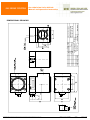
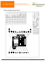
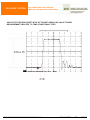
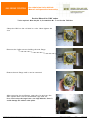
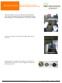
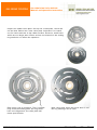
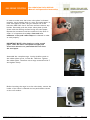
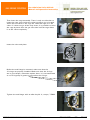
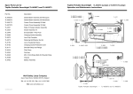
Gas Admission Valve GAV-40
Manual and Operation Instruction
1. TECHNICAL SPECIFICATIONS & OPERATION MANUAL
The GAV solenoid operated gas admission valve is designed for use on
four-cycle turbo-rcharged engines to govern the required amount of
fuel admitted into the inlet port of the cylinder head depending on
engine speed and load.
To govern the required amount of gas by means of the GAV, the
INCON electronic control system must be used for the valve control.
The engine load and speed are governed by the amount of gas
admitted into the inlet port which is proportional to the duration of the GAV valve
opening.
The GAV valve must assure rapid valve opening and closing (a fast response to the
control signal) together with reliable valve opening for the whole requested period of
time.
Consequently, the GAV valve features short travel, the moving valve plate is opened
by the solenoid force and closed by the spring force together with gas pressure. The
design provides a complete seal in the closed position of the valve.
Caution: The GAV valve must not be used as a shut off valve. To serve this purpose,
an independent shut off gas valve must be installed.
Technical Specifications:
Operating voltage
Cross-sectional area of flow
Lift
Working medium
Switching frequency
Response (assumes the use of an INCON control)
- time to full open
- time to full closed
Ambient temperature (permanently)
Ambient temperature (short-term)
Protection class
Classification for use in atmospheres:
Max. gas supply pressure
Max. Air manifold pressure
Max. gas pressure difference
Max. Backfire pressure
Inlet gas temperature
Solenoid core resistance
W:\DOKUMENTATION 2\Gas Motoren\GAV\Dokumentation\4014-V1.0-Gas Admission Valve GAV 40 Specifications-06-11-01-dh-en.doc
150 VDC
700 sq.mm
0.9 mm
Gaseous fuel (natural gas etc.)
12.5 Hz max.
0.003 s max.
0.003 s max.
-40…..+100 °C
125 °C max.
IP 64
Non-explosive atmosphere
500kPa (5 bar)
300kPa (3 bar)
200kPa (2 bar)
50kPa (0.5 bar)
60 °C max.
38.4 Ω +/- 5%
4014-V1.0 03.11.2006
mh/dh
Page 1 of 14
Gas Admission Valve GAV-40
Manual and Operation Instruction
2. INSTALLATION, OPERATION, MAINTENANCE
The GAV valve installation
1. The GAV valve Installation, Operation and Maintenance Manual must be read
carefully prior to installation.
2. The GAV valve can be mounted on the manifold in any position.
3. Make sure that the O-ring at the valve inlet and outlet is clean and properly located.
4. Evenly and gradually tighten the M8 mounting screws to max. torque (20 Nm). Use
a lock-washer in accordance with DIN 137 A.
5. The solenoid operated valve is controlled by a cable with a square section of
1.5mm2. The mating connector type DIN 43650 comes along with the valve.
6. The gas inlet hole is recommended to be equipped with a flexible hose (mounted
through an adapter) to avoid unnecessary stress affecting the valve body. Mount
and tighten the flexible hose on the adaptor prior to its installation on the valve.
7. After installation, all joints which can be dismantled (including the inlet and outlet
flange), must be checked for gas leaks e.g. by means of a foam-forming agent.
MAINTENANCE, TROUBLESHOOTING
Provided that good gas filtration, in accordance with the technical parameters has been
assured, the valve does not need any maintenance.
Should any valve defect be found (leakage, failure to function etc.) the valve has to be
replaced. Don’t repair a valve without the appropriate service instruction and the
necessary knowledge.
Should leakage exceed allowed limits, the valve is disassembled (as instructed) so that
sealing surfaces of the valve can be checked and cleaned. After assembly, the valve
closing tightness test is repeated and evaluated.
Caution:
The valve seat can be cleaned on the contact surface by lapping or sand paper on a flat
plane. The moving plate should never be cleaned by lapping or sand paper.
Within the warranty period, repairs of the valve may be carried out by the valve
manufacturer only.
W:\DOKUMENTATION 2\Gas Motoren\GAV\Dokumentation\4014-V1.0-Gas Admission Valve GAV 40 Specifications-06-11-01-dh-en.doc
4014-V1.0 03.11.2006
mh/dh
Page 2 of 14
Gas Admission Valve GAV-40
Manual and Operation Instruction
RECOMMENDED MAINTENANCE INTERVALS
2000 hours of operation
Operational check of all valve joints which may be dismantled for leakage, including
inlet and outlet flange: the valve is mounted on the engine and the check is made by
means of a gas leakage detector or foam-forming agent.
3000 hours of operation
Valve leakage check and valve closing tightness check in accordance with instructions.
6000 hours of operation
Valve O-rings replacement.
Cage assembly replacement
Lower valve plate replacement
Recommended Replacement Parts
O-ring set (positions 14 and 15)
Cage assembly (position 2,3,4 and 5)
Lower valve plate (position 6)
Accessories supplied with the valve
O-Ring: 46 X 2 (Pos. 14)
O-Ring: 64.77 X 2.62 (Pos. 15)
Mating Connector: EC 1120, DIN 43650
Packaging, Transport, Storage
The solenoid operated valve is packed in a polyethylene bag. In transit and storage, the
packed product must be protected against mechanical damage.
If possible, valves should be stored indoor and protected against weather and other
effects to avoid their contamination, damage and deterioration.
Warranty
The manufacturer provides a Warranty for the purchased GAV valves which expires
upon the earliest of 12 months from delivery or 2000 hours of operation.
Data for Delivery
The order has to specify:
The number of units. Valve type (preliminary consultation with the manufacturer is
advisable).
For accessories, the replacement parts order should include a position in accordance
with an outline drawing and parts list and if you need replacement parts for the valve
purchased, specify the valve serial number.
W:\DOKUMENTATION 2\Gas Motoren\GAV\Dokumentation\4014-V1.0-Gas Admission Valve GAV 40 Specifications-06-11-01-dh-en.doc
4014-V1.0 03.11.2006
mh/dh
Page 3 of 14
Gas Admission Valve GAV-40
Manual and Operation Instruction
TESTING
Valve closing tightness test
1. The valve is checked under conditions and with equipment corresponding with its
operation.
2. The test substance is filtrated (5 micrometer) air with 2 bar pressure.
3. The testing equipment consists of the test substance source (air with filtration of 5
micrometers) and 2 bar pressure and connecting piping (DN 10 mm) with a pressure
gauge for measuring the valve inlet pressure.
4. Criteria of allowed GAV valve closing tightness: Opening of the valve plate not
before 0.5 bar.
Leakage test
For a leakage test, an air pressure source with the highest working pressure (2 bar) will be
used. The test substance supply will be connected to the inlet part of the valve.
Leakage will be considered as satisfactory if within 3 minutes no measurable or visible
(foam-forming agent) leakage is detected, which is equal to zero pressure drop once the
inlet pressure ball valve is closed.
Supporting Documents
• Declaration of Conformity
• Dimensional drawing
• Section drawing and parts list
• Valve Test Record Sheet with attached graph on valve travel measurement related
to time (functional test)
• GAV 40 valve Disassembly and Assembly Instructions (for replacement of main
parts)
Prepared by: Daniel Huegli & Bernhard Suter
Date: November 29.2006
W:\DOKUMENTATION 2\Gas Motoren\GAV\Dokumentation\4014-V1.0-Gas Admission Valve GAV 40 Specifications-06-11-01-dh-en.doc
4014-V1.0 03.11.2006
mh/dh
Page 4 of 14
Gas Admission Valve GAV-40
Manual and Operation Instruction
DECLARATION OF CONFORMITY
Manufacturers Name
Huegli Tech AG (Ltd.)
Manufacturers Address
Murgenthalstrasse 30, CH-4900 Langenthal
Model Name/Number
Gas admission valves, GAV – 20, GAV – 40
Product Description and Function:
The GAV solenoid-operated gas admission valve is designed for use on four-cycle
supercharged gas engines to govern the required amount of fuel admitted into the inlet
runner of the cylinder head depending on engine speed and load. The product is intended
for use in non-explosive atmospheres. The solenoid operated gas admission valve must not
be used as a stop valve (safety valve).
We hereby declare and confirm that
A. The specified product is safe under conditions of its ordinary and intended use (as
described in its Operation Manual) and actions have been taken to assure
conformity of all launched products with technical specifications, basic relevant
regulatory requirements and requirements of technical regulations specified in
Section B.
B. The characteristics of the product meet all applicable technical requirements set out
in:
1. 94/9/EC Council directive of March 1994 on the approximation of the laws of
the member states concerning equipment and protective systems intended for
use in potentially explosive atmospheres
2. 73/23/EEC council directive of February 1973 on the harmonization of the
laws of the member states relating to electrical equipment designed for use
within certain voltage limits.
3. EN 60204-1: Safety of machinery – Electrical equipment of machines EN
60204-1
4. EN 61010-1: Safety requirements for electrical equipment for measurement,
control and laboratory use - Part 1: General requirements
5. EN50028: Electrical apparatus pro potentially explosive atmospheres Part 8
We, the undersigned, herby declare that the equipment specified above conforms to the
above directive(s).
Manufacturer
Full name
Daniel Huegli
Position
President
Place
CH-4900 Langenthal, Switzerland
Date
1. November 2006
W:\DOKUMENTATION 2\Gas Motoren\GAV\Dokumentation\4014-V1.0-Gas Admission Valve GAV 40 Specifications-06-11-01-dh-en.doc
4014-V1.0 03.11.2006
mh/dh
Page 5 of 14
Type
Serie
HUEGLI TECH AG (LTD)
4900 LANGENTHAL SWITZERLAND
W:\DOKUMENTATION 2\Gas Motoren\GAV\Dokumentation\4014-V1.0-Gas Admission Valve GAV 40 Specifications-06-11-01-dh-en.doc
4014-V1.0 03.11.2006
Rev
Date
Name
2.3 kg
Date
25.11.05
Name
bs
HUEGLI TECH AG
4900 Langenthal
Switzerland
Scale
Drawn
Appr.
Weight
Customer
Drawing Nr.
Document:
GS-1360
Gas Admission Valve
Dimensional Drawing
GAV-20-S2 / GAV-40-S2
Gas Admission Valve GAV-40
Manual and Operation Instruction
DIMENSIONAL DRAWING
mh/dh
Page 6 of 14
W:\DOKUMENTATION 2\Gas Motoren\GAV\Dokumentation\4014-V1.0-Gas Admission Valve GAV 40 Specifications-06-11-01-dh-en.doc
Rev
Date
Name
4014-V1.0 03.11.2006
Date
01.11.06
O-Ring 66X2
O-Ring 68X2
O-Ring 62X2
O-Ring 46X2
1
1
1
1
1
13
14
15
16
Allen screw M5X35 BN3
1
4
1
4
20
21
22
23
Name
kzj
Valve top with coil
1
19
Allen screw M5X16 BN3
18
Customer
Drawing Nr.
Document:
GS-1492
General Assembly
GAV-40-S2
Screw M3X10 BN330
Connector socket
Gasket
Lock-washer M5 BN782
4
8
17
Pin 2.5X5 BN1208
O-Ring 64.77X2.62
Closing flange
Lower valve disk
12
HUEGLI TECH AG
4900 Langenthal
Switzerland
Scale
Drawn
Appr.
Weight
Valve plate
Screw M6X20
1
1
6
7
Spring
Disk
10
1
5
Cage
1
1
4
1
1
3
Valve housing
Armature
9
1
2
DESIGNATION
BENENNUNG
8
1
1
1
QTY.
ANZ.
ITEM
POS.
Gas Admission Valve GAV-40
Manual and Operation Instruction
SECTION DRAWING AND PARTS LIST
mh/dh
Page 7 of 14
Gas Admission Valve GAV-40
Manual and Operation Instruction
VALVE TEST RECORD SHEET WITH ATTACHED GRAPH ON VALVE TRAVEL
MEASUREMENT RELATED TO TIME (FUNCTIONAL TEST)
W:\DOKUMENTATION 2\Gas Motoren\GAV\Dokumentation\4014-V1.0-Gas Admission Valve GAV 40 Specifications-06-11-01-dh-en.doc
4014-V1.0 03.11.2006
mh/dh
Page 8 of 14
Gas Admission Valve GAV-40
Manual and Operation Instruction
Service Manual for GAV valves
Tools required: Allen key Nr. 4; Screwdriver Nr. 7 and Loctite 743 blue
Clamp the GAV on the coil side in a vice. Hand tighten the
vice
Remove the 4 allen screws holding the end flange
Rotate the end flange until it can be removed
After removing the end flange, open the vice and turn the
GAV upside down until the assembled cage falls out.
Note: Don't drop the cage from a too high altitude, since it
could damage the rubber valve plate.
W:\DOKUMENTATION 2\Gas Motoren\GAV\Dokumentation\4014-V1.0-Gas Admission Valve GAV 40 Specifications-06-11-01-dh-en.doc
4014-V1.0 03.11.2006
mh/dh
Page 9 of 14
Gas Admission Valve GAV-40
Manual and Operation Instruction
Clamp the cage in to the vice between the anker plate.
Note: Don't overtorque the vice as the anker plate could
suffer damage. It is recommended to use soft vice clamps.
Unscrew the centre screw until the rubber plate can be
removed.
Disassemble the complete cage. Make sure all parts are
cleaned before inspection. Use non aggressive petrol for
cleaning the parts.
W:\DOKUMENTATION 2\Gas Motoren\GAV\Dokumentation\4014-V1.0-Gas Admission Valve GAV 40 Specifications-06-11-01-dh-en.doc
4014-V1.0 03.11.2006
mh/dh
Page 10 of 14
Gas Admission Valve GAV-40
Manual and Operation Instruction
Inspect the rubber valve plate. On top see a used plate, which still
can be used. Below see a new valve plate. Important is to watch
out for cracks and tear in the rubber surface. However, small holes
which are not larger than 0.5mm and are not located on the sealing
ring-marks do not affect the operation.
Plate which was in operation. The 6 visuable
rings mark the sealing plate. As long these
have no infringement, the valve plate still
meets specification.
W:\DOKUMENTATION 2\Gas Motoren\GAV\Dokumentation\4014-V1.0-Gas Admission Valve GAV 40 Specifications-06-11-01-dh-en.doc
New valve plate which has never been in use.
No ring markings can be seen.
4014-V1.0 03.11.2006
mh/dh
Page 11 of 14
Gas Admission Valve GAV-40
Manual and Operation Instruction
In order to make sure the lower valve plate is cleaned
properly, use a lapping disk or a very fine sand paper. In
case sand paper is used, the grit number has to be
between 280-320. Use a flat even surface without any
bumbs. Smoothly push the lower valve plate up and
down with the sealing surface facing the sand paper.
Repeat the movement until the surface of the valve is
clean. It is important that only a few tenth of a
millimetre of the peak radius shape are cleaned in order
to seal properly.
IMPORTANT NOTE: After lapping or using a sand
paper, clean the lower valve plate toroughly and
assure that there are no particulates left over from
the sand paper.
Assemble the complete cage. Loctite shall be used on
the rubber plate screw, Loctite Nr. 743 blue. Tighten
the rubber plate. Therefore use a large screwdriver Nr.7
and tighten firmly.
Before inserting the cage in to the valve body, ensure the
inside of the valve is cleaned and no particulates remain
on the coil surface.
W:\DOKUMENTATION 2\Gas Motoren\GAV\Dokumentation\4014-V1.0-Gas Admission Valve GAV 40 Specifications-06-11-01-dh-en.doc
4014-V1.0 03.11.2006
mh/dh
Page 12 of 14
Gas Admission Valve GAV-40
Manual and Operation Instruction
Then insert the cage assembly. There is only one direction to
insert the cage since inside the valve housing a pin is located,
which has to match to the cage slit. Slide the cage in to the
valve. If it does not go all the way down, it is possible to twist
the cage by hand from the gas inlet side until the cage slides
in to the valve completely.
Insert the valve end plate.
Before the end flange is mounted, make sure that the
2 O-rings are properly installed. Make sure that the O-rings
are in good shape, otherwise replace them. It is recommended
to use a fingertip of grease to smoothen the O-rings.
Tighten the end flange with an allen key Nr. 4, torque, 7.5NM.
W:\DOKUMENTATION 2\Gas Motoren\GAV\Dokumentation\4014-V1.0-Gas Admission Valve GAV 40 Specifications-06-11-01-dh-en.doc
4014-V1.0 03.11.2006
mh/dh
Page 13 of 14
Gas Admission Valve GAV-40
Manual and Operation Instruction
Before mounting the valve on to the engine, be assured
that the O-Ring facing the engine is in good shape and
has no infringement. Also use a finger tip of grease to
smoothen the O-ring.
Mounting the valve on the engine block, make sure that
the mounting surface is cleaned before positioning
the valve. The 4 M8 nuts are tightened
with 20 NM each.
W:\DOKUMENTATION 2\Gas Motoren\GAV\Dokumentation\4014-V1.0-Gas Admission Valve GAV 40 Specifications-06-11-01-dh-en.doc
4014-V1.0 03.11.2006
mh/dh
Page 14 of 14