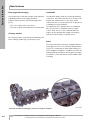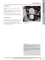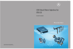
1
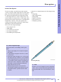
New Generation of 4-Cylinder
Inline Engines, OM 651
Introduction into Service Manual
Daimler AG, GSP/OI, HPC R 822, D-70546 Stuttgart
Order No. 6516 1364 02 – Printed in Germany – 08/08
– This printout will not be recorded by the update service. Status: 09 / 2008 –
Mercedes-Benz Service
Introduction of New Generation of 4-Cylinder
Inline Engines, OM 651
Daimler AG · Technical Information and Workshop Equipment (GSP/OI) · D-70546 Stuttgart
– This printout will not be recorded by the update service. Status: 09 / 2008 –
Information and copyright
Ordering workshop information
All printed workshop information from GSP / OI, such as Introduction into Service
Manuals, System Descriptions, Function Descriptions, Technology Guides, Technical Data Manuals and adhesive labels, can be ordered as follows:
Within Germany
Through our GSP / OI Shop on the Internet
Link:
http: / / gsp-ti-shop.de
or alternatively
E-mail: [email protected]
Phone: +49-(0)1805 / 010-7979
Fax:
+49-(0)1805 / 010-7978
Outside Germany
Please get in touch with the contact person responsible for your market.
Product portfolio
You can also find comprehensive information on our complete product portfolio
in our Internet portal.
Link:
http: / / open.aftersales.daimler.com
Questions and suggestions
If you have any questions or suggestions concerning this product, please write to
us.
E-mail: [email protected]
Fax:
+49-(0)18 05 / 0 10-79 78
or alternatively
Address: Daimler AG
GSP / OIS
HPC R822, W002
D-70546 Stuttgart
© 2008 by Daimler AG
This document, including all its parts, is protected by copyright.
Any further processing or use requires the previous written consent of
Daimler AG, Department GSP / OIS, HPC R822, W002, D-70546 Stuttgart.
This applies in particular to reproduction, distribution, alteration, translation,
microfilming and storage and / or processing in electronic systems, including
databases and online services.
Image no. of title image:
Order no. of this publication:
P01.00-3119-00
6516 1364 02
08 / 2008
– This printout will not be recorded by the update service. Status: 09 / 2008 –
Contents
Preface
5
Overview
Brief description
6
Engine data
7
Highlights
8
Engine views
9
System comparison
10
At a glance
11
Mechanical system
Crankcase
12
Cylinder head
13
Oil pan
14
Crankshaft assembly
15
Valve assembly
17
Gear drive
18
Belt drive
19
Combustion
Common rail injection
20
Charging
24
Air supply
29
Exhaust system
32
Exhaust system
34
Introduction of New Generation of 4-Cylinder Inline Engines, OM 651 q
– This printout will not be recorded by the update service. Status: 09 / 2008 –
3
Contents
Cooling and lubrication
Engine cooling
36
Engine lubrication and oil circuit
38
Oil pump
40
Coolant pump
41
Electrical and electronic systems
Engine control unit
42
Glow system
43
Pneumatic system
Vacuum control
44
Environmental protection
Emission reduction
46
Service information
New features
48
Special tools
4
Engine
50
Abbreviations
55
Index
56
q Introduction of New Generation of 4-Cylinder Inline Engines, OM 651
– This printout will not be recorded by the update service. Status: 09 / 2008 –
Preface
Dear Reader,
This Introduction into Service Manual presents the
new 4-cylinder inline diesel engine 651 from
Mercedes-Benz.
It allows you to familiarize yourself with the technical
highlights of this new engine in advance of its market
launch. This brochure primarily intended to provide
information for people employed in service, maintenance and repair as well as for aftersales staff. It is
assumed that the reader is already familiar with the
Mercedes-Benz model series and major assemblies
currently on the market.
In terms of the contents, the emphasis in this Introduction into Service Manual is on presenting new and
modified components, systems, system components
and their functions.
This Introduction into Service Manual aims to provide
an overview of the technical innovations and an insight
into their complicated designs.
However, this Introduction into Service Manual is not
intended as a basis for repair work or technical diagnosis. For such needs, more extensive information is
available in the Workshop Information System (WIS)
and in the Diagnosis Assistance System (DAS).
WIS is updated monthly. Therefore, the information
available there reflects the latest technical status of
our vehicles.
The contents of this brochure are not updated and no
provision is made for supplements. We will publicize
modifications and new features in the relevant WIS
documents. The information presented in this Introduction into Service manual may therefore differ from
the more up-to-date information found in the WIS.
All information relating to technical data, equipment
and options is valid as of the copy deadline in July 2008
and may therefore differ from the current production
configuration.
Daimler AG
Technical Information and Workshop Equipment
(GSP / OI)
Introduction of New Generation of 4-Cylinder Inline Engines, OM 651 q
– This printout will not be recorded by the update service. Status: 09 / 2008 –
5
Overview
Brief description
Engine model series 651
The new generation of the 4-cylinder diesel engine
651 equipped with the second-generation Common
Rail Direct Injection (CDI) system from Delphi will be
launched on the market as of October 2008.
Engine 651 has a rated output of 150 kW with a
displacement of 2,143 cm3 and a consumption of just
5.4 liters of diesel fuel per 100 kilometers. Despite
this high output and an engine torque of 500 Nm,
emissions of CO2 have been further reduced. In addition, the engine meets the future Euro 5 standard.
A central feature of the new engine is its dual stage
turbocharging system. The system combines a small
high-pressure turbocharger with a large low-pressure
turbocharger. Engine 651 also features two
Lanchester balance shafts to make the engine run
more smoothly.
Engine 138
2.6 l displacement and 33 kW output. Installed in the
Mercedes-Benz 260 D, the world's first diesel passenger
car, in 1936.
In order to meet the new legal requirements of the
Euro NCAP crash tests with respect to improved
pedestrian protection, the gear drive has been located
on the output side together with the chain drive. The
increased space between the engine and engine hood
reduces the risk of injury for pedestrians.
Engine 651
2.2 l displacement and 150 kW output. Installed in the
C-Class as of October 2008.
i Note
A detailed description of the new CDI system can
be found in the System Description for engine 651.
Order number: 6516 1363 02
6
q Introduction of New Generation of 4-Cylinder Inline Engines, OM 651
– This printout will not be recorded by the update service. Status: 09 / 2008 –
Comparison
Engine 646.821 EVO
Engine 651.911
Difference
Displacement
cm3
2,148
2,143
–0.2%
Rated output
kW
at rpm
125
3,800
150
4,200
+20%
Rated torque
Nm
at rpm
400
2,000
500
1,600…1,800
+25%
Maximum rpm
rpm
4,900
5,200
+6%
Overview
Engine data
Engine 646.821 EVO
Engine 651.911
n
Engine speed
M Torque
P
Output
Introduction of New Generation of 4-Cylinder Inline Engines, OM 651 q
– This printout will not be recorded by the update service. Status: 09 / 2008 –
7
Overview
Highlights
New features
Thermal management
Based on the use of the latest innovative technologies,
engine 651 sets a new standard in terms of output and
torque characteristics, economy, exhaust emission
levels and smooth running. The engine features a
number of new developments which cannot be found
in this combination in any other series-produced
passenger car diesel engine.
The new thermal management system consists of:
• Shutoff-capable coolant pump
• Cylinder head with two-piece water jacket
• Shutoff-capable oil spray nozzles combined with
piston crown cooling
• Oil pump volume-controlled at clean oil side
Technology
The most important technical features of the new
engine are:
• Dual stage turbocharging with fixed geometry
• Directly actuated piezo injectors
• Gear drive in combination with a chain drive on the
output side
• Intake air-cooled engine control unit
on air filter housing
• Main bearing bridge with integrated
Lanchester housing
• Two Lanchester balance shafts
• Drive gear friction welded to crankshaft
• Vibration dampers
(quadruple bolted)
• Universal timing case cover for adaptation to
various transmission models
• Major assembly carrier with variable arrangement
as per vehicle concept
• Two knock sensors
• Two-piece oil pan (noise optimized)
• Oil pan bottom section made of plastic
8
i Note
i Note
Friction-welded connections involve connecting
two parts together by force. The application of friction and pressure produces a fixed connection
without the use of welding consumable.
Further information on repairing and maintaining
engine 651 can be found in the Workshop Information System (WIS).
q Introduction of New Generation of 4-Cylinder Inline Engines, OM 651
– This printout will not be recorded by the update service. Status: 09 / 2008 –
Overview
Engine views
Engine 651: Side view from left
Engine 651: Side view from right
Introduction of New Generation of 4-Cylinder Inline Engines, OM 651 q
– This printout will not be recorded by the update service. Status: 09 / 2008 –
9
Overview
System comparison
Comparison
Market launch
Engine 646.821EVO
C 220 CDI
Engine 651.911
C 250 CDI
06 / 2006
10 / 2008
Combustion system
Diesel direct injection
No. of cylinders
4
Engine configuration
Inline
Bore
mm
88.3
83.0
Stroke
mm
88.3
99.0
e
16.5:1
16.2:1
Duplex chain
Simplex chain
2
2
Cup tappet
with hydraulic valve
clearance compensation
Roller-type cam follower
with hydraulic valve
clearance compensation
1-stage turbocharging with
variable turbine geometry
2-stage turbocharging with
fixed geometry
Electric
Pneumatic
Intake port shutoff,
exhaust gas recirculation
(EGR) with separate EGR
cooler
Intake port shutoff, EGR
cooling and EGR bypass
Solenoid injector
Directly controlled piezo
injector
17
19
Compression ratio
Camshafts – drive
Camshafts – number
Valve actuation
Turbocharger type
Boost pressure control
Measures for low-emission
combustion
Fuel injector – type
Fuel injector – diameter
mm
Firing order
1-3-4-2
Oil pump – drive
10
Simplex chain
Gear drive
Alternator – current rating
A
200
180
Engine weight DIN (dry) approx.
kg
190
203
q Introduction of New Generation of 4-Cylinder Inline Engines, OM 651
– This printout will not be recorded by the update service. Status: 09 / 2008 –
Objective
Measures on engine 651
Optimized comfort
Stiffer crankcase with full-length crankshaft bearing bridge
Overview
At a glance
Wide crankshaft main bearing; friction-optimized with center bearing
Two low-positioned Lanchester balance shafts for smooth engine running
Plastic cylinder head cover with integrated ventilation
Maintenance-free, long-life simplex chain as camshaft drive
Engine cover with adjusted acoustic damping
Improved fuel
economy
Optimized flow conditions (air ducting, intake ports)
Dual stage turbocharging
Optimized charge air cooling and exhaust gas recirculation cooling
Reduction in friction through gear drive and balance shafts mounted
on roller bearings
Compliance with
exhaust emissions
standards (Euro 5
standard)
Optimized shape of combustion chamber
7-hole injection nozzles
More precise injection times
Optimized air ducting
Exhaust gas recirculation (EGR) with EGR pre-cooler and EGR cooler, EGR valve and
switched EGR bypass
Electric intake air throttling
Shutoff-capable coolant pump and shutoff-capable oil spray nozzles
Exhaust system with oxidation catalytic converter and diesel particulate filter
Introduction of New Generation of 4-Cylinder Inline Engines, OM 651 q
– This printout will not be recorded by the update service. Status: 09 / 2008 –
11
Mechanical system
Crankcase
General
When engine 651 was developed, the design of the
crankcase was based on an overall concept with optimized spatial features. Accordingly, the gear drive
with the oil pump drive and the Lanchester balance
shafts are positioned on the output side. The cast iron
crankcase is manufactured by sand casting.
The new design concept provides the following advantages:
• 4 cm shorter crankcase compared to predecessor
version
• Improved pedestrian protection through
positioning of gear drive and camshaft drive on
output side
• Universal timing case cover for adaptation to
various transmission models
Crankcase
1
12
Crankcase
2
Oil spray nozzle shutoff valve
q Introduction of New Generation of 4-Cylinder Inline Engines, OM 651
– This printout will not be recorded by the update service. Status: 09 / 2008 –
General
The cylinder head is made of high-strength aluminum.
It is equipped with two camshafts and four valves per
cylinder. The cylinder head cover is made of plastic
with integrated ventilation. The cylinder head is characterized by the following new features:
• Maximum ignition pressure of 200 bar (previously
160 bar)
• Tangential and spiral intake ports
• Bore for piezo injector of 19 mm diameter
The improved thermal management system is particularly beneficial in those areas which are exposed to
very high temperatures. The high ignition pressure of
200 bar is only made possible by targeted cooling of
the individual components. The increased pressure
potential and optimized injection quantity are responsible for the high engine torque of 500 Nm and the
engine output of 150 kW.
Mechanical system
Cylinder head
The upper duct of the two-piece water jacket supplies
the cylinder head with coolant. The advantages of the
two-piece water jacket include:
• Greater structural rigidity
• Better heat dissipation
• Improved thermal management
Cross-section of cylinder head
1
2
3
Ventilation
Main bearing bridge
Cylinder head cover
4
5
6
Glow plug
Exhaust valve
Piezo injector
7
8
9
Intake valve
Valve spring
Valve clearance compensation
Introduction of New Generation of 4-Cylinder Inline Engines, OM 651 q
– This printout will not be recorded by the update service. Status: 09 / 2008 –
13
Mechanical system
Oil pan
Special design features
•
•
•
•
Two-piece design
Lower section of oil pan made of plastic
Noise-optimized
Service-optimized and cost-optimized replacement
parts
• Bolts secured to prevent them being lost
• Installation can be checked via special pins on seal
Oil pan
1
2
Upper section of oil pan
Seal with pins
3
4
Lower section of oil pan (plastic)
Bolts with retainer (anti-loss)
i Note
Temporary level fluctuations are balanced out by the volume of the housing and the size of the drain bores
in the oil level check switch. This prevents unnecessary warning messages e.g. triggered by cornering.
14
q Introduction of New Generation of 4-Cylinder Inline Engines, OM 651
– This printout will not be recorded by the update service. Status: 09 / 2008 –
Crankshaft
Connecting rods
The forged crankshaft with eight counterweights is
supported by five bearings for effective vibration
damping. The radiuses of the crank pins are rolled to
give them high strength. In addition, the connection
between the drive gear and crankshaft is friction
welded.
The weight-optimized connecting rods are made of
forged steel and are cracked at the level of the bearing
shells.
The vibration damper is fixed to the crankshaft with a
fourfold threaded connection.
Mechanical system
Crankshaft assembly
Balance shafts
Two Lanchester balance shafts are integrated in the
main bearing bridge and mounted on three roller bearings. They are driven in opposite directions by the gear
drive to counteract the inertia forces of the second
order which are generated. This ensures smooth
engine running.
Crank assembly with gear drive
1
2
3
4
Oil and vacuum pump drive gear
Crankshaft gear
Crankshaft
High-pressure pump drive gear
5
6
7
Intermediate gears
(tensioning gears)
Piston
Connecting rod
8
9
Vibration damper
Lanchester drive gears
i Note
The aluminum pistons run in friction-optimized cast-iron cylinder barrels. On this engine, they are all manufactured uniformly. There is therefore no differentiation between A, B or X sizes on this engine.
Introduction of New Generation of 4-Cylinder Inline Engines, OM 651 q
– This printout will not be recorded by the update service. Status: 09 / 2008 –
15
Mechanical system
Crankshaft assembly
Camshafts
Sensor wheel
The gear drive drives the camshaft sprockets and the
connected camshafts via a timing chain. The maintenance free timing chain is tried and tested and has
proven longevity. The cams are fixed to the camshaft
by means of internal high-pressure forming (IHU).
The sensor wheel is fixed to the exhaust camshaft. In
combination with the Hall sensor, the sensor wheel
makes it possible to determine the camshaft position
and rpm.
Camshaft sprocket
The camshaft sprocket is connected to the camshaft
by a center bolt. The center bolt of the camshaft has a
left-hand thread.
The Hall sensor generates a magnetic field through a
built-in permanent magnet. The magnetic field is periodically interrupted by an orifice plate on the sensor
wheel while the engine is running. The signal which
this generates is used by the CDI control unit and
serves as a substitute signal for emergency engine
operation if the position sensor for the crankshaft
fails.
Exhaust camshaft with sensor wheel
1
16
Drive gear
2
Exhaust camshaft
3
Sensor wheel with orifice plate
q Introduction of New Generation of 4-Cylinder Inline Engines, OM 651
– This printout will not be recorded by the update service. Status: 09 / 2008 –
Valve assembly with hydraulic valve clearance compensation
The valve assembly was modified with the aim of optimizing friction and reducing the moved masses.
The camshafts control two intake valves and two
exhaust valves per cylinder. This valve timing system
uses low-friction roller-type cam followers with
hydraulic valve clearance compensation.
Mechanical system
Valve assembly
Valve assembly
1
2
3
4
5
Slide rail
Timing chain
Camshaft drive gears
Intake camshaft
Exhaust camshaft
6
7
8
9
10
Sensor wheel with orifice plate
Roller-type cam followers
Hydraulic valve clearance compensator
Chain tensioner
Timing chain drive gear
Introduction of New Generation of 4-Cylinder Inline Engines, OM 651 q
– This printout will not be recorded by the update service. Status: 09 / 2008 –
17
Mechanical system
Gear drive
Gear drive
One of the most important innovations is the gear
drive in combination with a chain drive on the output
side. The reduction in the vibrations produced by the
crankshaft results in a noticeably smoother running
engine.
The following components are driven by the new gear
drive system:
•
•
•
•
Lanchester balance shafts
Oil pump
High pressure pump
Vacuum pump via continuous central drive shaft of
oil pump
Gear drive
1
2
3
18
Intermediate gears
Crankshaft gear
Lanchester drive gears
4
5
6
Oil and vacuum pump drive gear
Drive sprocket
High-pressure pump drive gear
q Introduction of New Generation of 4-Cylinder Inline Engines, OM 651
– This printout will not be recorded by the update service. Status: 09 / 2008 –
Belt routing
The ancillary assemblies are driven by a single-piece,
low-maintenance poly-V belt. The poly-V belt is
tensioned by an automatic belt tensioner with
tensioner pulley.
Mechanical system
Belt drive
Belt routing
1 Alternator
2 Belt pulley
3 Guide pulley
4 Coolant pump
5 Power steering pump
6 Belt tensioner with tensioner pulley
7 Refrigerant compressor
8 Guide pulley
9 Major assembly carrier
Introduction of New Generation of 4-Cylinder Inline Engines, OM 651 q
– This printout will not be recorded by the update service. Status: 09 / 2008 –
19
Combustion
Common rail injection
Injection technology
Engine 651 uses the new Common Rail technology of
the second generation from Delphi. The maximum
injection pressure has been increased by 400 bar to
2,000 bar. A new feature is the piezo injector concept
with direct nozzle needle control. Direct actuation
allows the injection volume to be changed quickly and
with the utmost precision.
The piezo injectors provide the following improvements:
• Greater flexibility for actuation of injection timing
points
• Lower fuel consumption
• Higher engine output
• Minimized combustion noise
• Reduced emissions
• Smoother engine running
20
The most important new features of the injection
system include:
• High-pressure pump with two pump elements
(max. injection pressure 2,000 bar)
• Electronic engine control with more advanced
actuation function for injection timing points
• Leak oil-free injection system with piezo injectors
The increase in engine output to 150 kW / 204 hp and
the increase in engine torque to 500 Nm was only
made possible by the increased pressure potential. At
the same time, the level of raw emissions produced by
the engine has been significantly improved.
q Introduction of New Generation of 4-Cylinder Inline Engines, OM 651
– This printout will not be recorded by the update service. Status: 09 / 2008 –
Piezo injectors
An important component of the new Common Rail
technology are the piezo injectors, which are an
entirely new development. The injector needle is actuated directly by a piezo-ceramic actuator, instead of
being moved by a hydraulic support system.
Compared to a conventional fuel injector, the piezo
injector injects fuel into the combustion chamber
more rapidly, with better atomization and with greater
precision.
Combustion
Common rail injection
A special feature of this system is that the piezo injectors open upon a voltage rise and not upon a voltage
drop.
Piezo injector
a Warning
Due to the risk of engine damage, no
connections on the injection system may be
disconnected while the engine is running.
The injector coupling may not be disconnected
and switched to ground while the engine is
running because this would trigger an injection.
a Warning! Risk of death!
During engine operation, a high voltage of up to
250 V is applied to the piezo injectors.
Introduction of New Generation of 4-Cylinder Inline Engines, OM 651 q
– This printout will not be recorded by the update service. Status: 09 / 2008 –
21
Combustion
Common rail injection
Advantages of the new injection technology
Injection quantity
The advantages gained with the new technology
include a larger available injection volume as well as
particularly fine and rapid metering of injection quantities due to finely tuned switching times. In combination with direct actuation of the piezo injectors by the
CDI control unit, the fuel injection process can be
even more precisely adjusted to the respective load
and rpm situation. This is achieved, for example,
through precise multiple injections which enable fuel
consumption, combustion noise and exhaust emissions to be reduced even further. The engine also runs
significantly more smoothly at idle.
The injection timing point and injection period are
determined by the following factors:
•
•
•
•
•
•
Direct actuation of piezoceramic element
Opening / closing speed of the nozzle needle
Needle lift
Nozzle geometry with 7-hole nozzle module
Engine load
Torque request
i Note
When working on the injection system (e.g. piezo
injector, pressure lines, rail, high-pressure pump)
particular care must be given to quality and cleanliness, as even the most minor contamination may
very quickly lead to complaints about engine
running characteristics and damage.
22
q Introduction of New Generation of 4-Cylinder Inline Engines, OM 651
– This printout will not be recorded by the update service. Status: 09 / 2008 –
Injection quantity correction
Zero quantity calibration
Injection quantity correction consists of two procedures:
The friction produced during opening and closing of
the piezo injectors causes wear on the nozzle seat of
the nozzle needle. This causes a change in the injection quantity over the service live of the injector.
• Main injection quantity correction
• Zero quantity calibration
Main injection quantity correction
With main injection quantity correction, the injected
fuel quantity is corrected using the oxygen sensor
upstream of the catalytic converter. The injection
quantity is changed until the specified lambda value
stored in the CDI control unit is reached.
Combustion
Common rail injection
This change in the injection quantity can be corrected
by adjusting the actuation duration (zero quantity calibration). On engines with the Delphi injection system,
correction is performed with the help of two knock
sensors.
CDI injection system
1
2
3
Fuel heating element
Fuel filter housing
Rail
4
5
6
Rail pressure sensor
Pressure line
Piezo injector
7
8
9
High-pressure pump
Quantity control valve
Pressure regulator valve
Introduction of New Generation of 4-Cylinder Inline Engines, OM 651 q
– This printout will not be recorded by the update service. Status: 09 / 2008 –
23
Combustion
Charging
General
With engine 651, Mercedes-Benz has continued the
development of dual stage turbocharging in its
4-cylinder inline diesel engines in a passenger car
(the predecessor with dual stage turbocharging is
engine 646 in the Mercedes-Benz Sprinter).
Design
The dual stage turbocharging system incorporates two
turbochargers that differ in size and a bypass control
system to achieve a high rated output and air mass
throughput even at low rpm. The boost pressure is
regulated via the boost pressure control flap (LRK),
the wastegate and the charge air bypass flap. The
control operations take into account the respective
engine torque request based on performance maps.
The effects on the engine include:
• Better cylinder charging and thus higher output
• Well-balanced torque curve at extremely high level
• Improved rated output with a well-balanced torque
curve
• Lower fuel consumption
• Long service life and high reliability
• Reduced nitrogen oxide (NOx) emissions
Function sequence of boost pressure control
For a better overview of how dual stage turbocharging
works, three different states of wide open throttle
operation have been selected. These states will be
used to explain and illustrate the exact process.
The following boost pressure control states are
described:
Advantages of dual stage, controlled turbocharging
This complicated control system which uses two
turbochargers to feed charge air to the engine in
accordance with its requirements has the following
advantages:
• Wide open throttle operation up to 1,200 rpm
• Wide open throttle operation between 1,200 and
2,800 rpm
• Wide open throttle operation as of 2,800 rpm
•
•
•
•
Noticeably more dynamic start-off behavior
No start-off sluggishness (turbo lag)
Well-balanced driving characteristics
Noticeably better driving performance throughout
the entire rpm range
• Good acceleration (high torque at low rpm)
• High-pressure turbocharger is designed to build up
boost pressure rapidly at low engine speeds
• Low-pressure turbocharger is designed to build up
high boost pressure with high gas flow at medium
and high engine speeds
24
q Introduction of New Generation of 4-Cylinder Inline Engines, OM 651
– This printout will not be recorded by the update service. Status: 09 / 2008 –
– This printout will not be recorded by the update service. Status: 09 / 2008 –
108
110
110 / 1
110 / 2
111
112
Exhaust manifold
High-pressure turbocharger (HD-Lader)
HD-Lader compressor impeller
HD-Lader turbine wheel
Vacuum unit (boost pressure control flap)
Adjustment rod (boost pressure control flap)
Dual stage turbocharging
113
120
120 / 1
120 / 2
121
122
Boost pressure control flap
Low-pressure turbocharger (ND-Lader)
ND-Lader compressor impeller
ND-Lader turbine wheel
Wastegate vacuum unit
Wastegate adjustment rod
123
124
125
126
Introduction of New Generation of 4-Cylinder Inline Engines, OM 651 q
Combustion
Wastegate
Charge air bypass flap vacuum unit
Charge air bypass flap adjustment rod
Charge air bypass flap
Charging
25
Combustion
Charging
Boost pressure control during wide open throttle operation up to 1,200 rpm
The boost pressure control flap (LRK) is almost closed
up to an engine speed of 1,200 rpm during wide open
throttle operation. In this state, the entire exhaust flow
flows over the turbine wheel of the high-pressure
turbocharger (HD-Lader) to the turbine wheel of the
low-pressure turbocharger (ND-Lader) and then to the
exhaust system.
The remaining exhaust energy acts on the turbine
wheel of the ND-Lader, which drives the compressor
impeller via the supercharger shaft. The ND-Lader
thus does not act as a hydrodynamic retarder. The
wastegate and charge air bypass flap are closed in this
operating condition.
The majority of the exhaust energy acts on the turbine
wheel of the HD-Lader, which generates the main part
of the required boost pressure. Despite the low
exhaust flow, this produces a high boost pressure
which builds up very quickly.
Schematic illustration of boost pressure control during wide open throttle operation up to 1,200 rpm
A Intake air
B Exhaust flow
1 High-pressure turbocharger
2 Low-pressure turbocharger
3 Boost pressure control flap (LRK)
26
4
5
6
7
8
9
Wastegate
Charge air bypass flap
Air filter
Charge air cooler
Throttle valve actuator
Intake manifold
10 Exhaust manifold
11 Exhaust gas recirculation (EGR)
pre-cooler
12 EGR actuator
13 EGR cooler
14 EGR bypass flap
q Introduction of New Generation of 4-Cylinder Inline Engines, OM 651
– This printout will not be recorded by the update service. Status: 09 / 2008 –
Boost pressure control during wide open throttle operation between 1,200 and 2,800 rpm
As of an engine speed of 1,200 rpm during wide open
throttle operation, the boost pressure control flap
(LRK) is opened in the working range (cross-section of
opening) of 5% to 95% depending on the boost pressure required.
In this state, the two turbochargers work together and
provide the required boost pressure jointly.
Combustion
Charging
The wastegate and charge air bypass flap are closed in
this operating condition.
As the cross-section of the LRK opening increases, the
ND-Lader is continuously engaged and a greater
exhaust volume flows through it. The intake of clean
air is further pre-compressed.
Schematic illustration of boost pressure control during wide open throttle operation between 1,200 and 2,800 rpm
A Intake air
B Exhaust flow
1 High-pressure turbocharger
2 Low-pressure turbocharger
3 Boost pressure control flap (LRK)
4
5
6
7
8
9
Wastegate
Charge air bypass flap
Air filter
Charge air cooler
Throttle valve actuator
Intake manifold
10 Exhaust manifold
11 Exhaust gas recirculation (EGR)
pre-cooler
12 EGR actuator
13 EGR cooler
14 EGR bypass flap
Introduction of New Generation of 4-Cylinder Inline Engines, OM 651 q
– This printout will not be recorded by the update service. Status: 09 / 2008 –
27
Combustion
Charging
Boost pressure control during wide open throttle operation as of 2,800 rpm
The LRK is fully open as of an engine speed of
2,800 rpm. This causes almost the entire flow of
exhaust gas to be fed nearly without loss to the lowpressure turbine via the bypass duct and limits the
level of exhaust back pressure.
In order to prevent pressure loss and additional
warming of the charge air as it flows through the highpressure compressor, the charge air bypass flap is
opened so that the main part of the air flow is guided
to the charge air cooler along a direct, low-loss path.
This procedure means that the HD-Lader no longer
makes any contribution to increasing the boost pressure. The HD-Lader has reached its choking limit. This
means that it can no longer generate boost pressure
and, in the event of further loading, the turbine speed
would drop off significantly.
The wastegate is used to regulate the turbine output
of the low-pressure turbine in the engine performance
map as required and depending on the load condition.
Depending on the load condition, the HD-Lader can
build up a high level of boost pressure at low engine
speeds and prevent overload of the ND-Lader at high
engine speeds.
Schematic illustration of boost pressure control during wide open throttle operation as of 2,800 rpm
A Intake air
B Exhaust flow
1 High-pressure turbocharger
2 Low-pressure turbocharger
3 Boost pressure control flap (LRK)
28
4
5
6
7
8
9
Wastegate
Charge air bypass flap
Air filter
Charge air cooler
Throttle valve actuator
Intake manifold
10 Exhaust manifold
11 Exhaust gas recirculation (EGR)
pre-cooler
12 EGR actuator
13 EGR cooler
14 EGR bypass flap
q Introduction of New Generation of 4-Cylinder Inline Engines, OM 651
– This printout will not be recorded by the update service. Status: 09 / 2008 –
Air ducting
The hot film mass air flow sensor (HFM) is located in
the clean air line downstream of the air filter housing.
It determines the mass and temperature of the intake
air and makes the measurement results available to
the motor electronics as input factors.
The throttle valve actuator influences the air volume
fed to the engine and the mixing ratio of charge air and
recirculated exhaust gas mixed in downstream of the
throttle valve. The air mixture is then fed directly to the
combustion chamber via the charge air manifold.
Combustion
Air supply
The low-pressure turbocharger draws in clean air
through the clean air line and air filter and compresses
it. The air compressed by the turbochargers flows
through the charge air cooler where it is cooled.
Air ducting
1
2
3
Air filter housing
Throttle valve
Charge air manifold
4
5
Clean air line
Charge air cooler
Introduction of New Generation of 4-Cylinder Inline Engines, OM 651 q
– This printout will not be recorded by the update service. Status: 09 / 2008 –
29
Combustion
Air supply
Intake port shutoff
The intake port shutoff (EKAS) function ensures the
best possible ratio between air mixing and air mass in
all engine load conditions and thus an optimal fill level.
This optimizes the exhaust characteristics and engine
output. The charge air manifold is made of plastic and
the flaps are made of metal.
When the engine switches from the partial load range
to the full load range, the flaps in the spiral intake
ports are opened according to performance maps.
In the event of a fault or if the supply voltage is interrupted, the flaps in the spiral intake ports are mechanically opened by the return springs.
In the charge air manifold, there is a permanently open
tangential intake port and a flap-controlled spiral
intake port for each cylinder. The flaps are connected
to each other by a shaft. The CDI control unit controls
the position of the flaps based on performance maps.
Charge air manifold
1
2
3
30
Actuator motor
Adjustment flap
Spiral intake port
4
5
Tangential intake port
Charge air manifold
q Introduction of New Generation of 4-Cylinder Inline Engines, OM 651
– This printout will not be recorded by the update service. Status: 09 / 2008 –
Throttle valve
The throttle valve actuator uses the throttle valve to
influence the air volume fed to the engine and the
mixing ratio of charge air and recirculated exhaust gas
mixed in downstream of the throttle valve.
Combustion
Air supply
When the engine is switched off, the throttle valve is
closed. This keeps engine vibrations at a low level
when the engine is switched off.
Throttle valve
1
Throttle valve
2
Throttle valve actuator
3
Charge air manifold
Introduction of New Generation of 4-Cylinder Inline Engines, OM 651 q
– This printout will not be recorded by the update service. Status: 09 / 2008 –
31
Combustion
Exhaust system
Exhaust gas recirculation
The exhaust system of engine 651 combines two technologies for emission reduction. Exhaust gas recirculation (EGR) reduces emissions of nitrogen oxide (NOx)
and exhaust treatment reduces the emission of hydrocarbons (HC) and soot particles.
The recirculated exhaust gas enters the EGR path via
a pre-cooler. There it is either cooled according to its
temperature or fed directly to the charge air. The
exhaust-air mixture enters the combustion chamber
directly via the charge air manifold.
With exhaust gas recirculation, part of the exhaust
flow is guided back through the EGR path to the
charge air.
Exhaust gas recirculation reduces the oxygen (O2)
concentration and combustion temperature.
Exhaust gas recirculation
1
2
32
EGR pre-cooler
EGR cooler
3
4
Charge air manifold
Exhaust manifold
q Introduction of New Generation of 4-Cylinder Inline Engines, OM 651
– This printout will not be recorded by the update service. Status: 09 / 2008 –
Exhaust gas recirculation path
Part of the exhaust gas enters the exhaust gas recirculation system via the exhaust manifold.
The EGR path is made up of the following components:
•
•
•
•
EGR pre-cooler
EGR actuator
EGR bypass flap
EGR cooler
The incoming quantity of exhaust gas is controlled by
the EGR actuator.
The CDI control unit actuates the EGR actuator via a
pulse width modulated signal, causing the EGR actuator to increase or reduce the size of the opening
cross-section of the EGR valve. In order to further
improve the efficiency, the exhaust gas can be
directed via the EGR cooler and cooled further
depending on the requirement.
Combustion
Exhaust system
However, if the temperature of the incoming exhaust
gas is too low, the path to the EGR cooler is closed via
a bypass flap and the exhaust gas is guided directly to
the charge air manifold. The switchover valve for the
bypass flap is controlled by a vacuum unit.
EGR path
1
2
3
EGR actuator
Vacuum unit
EGR bypass
4
5
6
EGR cooler
EGR pipe
EGR pre-cooler
Introduction of New Generation of 4-Cylinder Inline Engines, OM 651 q
– This printout will not be recorded by the update service. Status: 09 / 2008 –
33
Combustion
Exhaust system
Oxidation catalytic converter
Diesel particulate filter (DPF)
The oxidation catalytic converter is part of the exhaust
system and is located in the exhaust tract downstream of the turbocharger.
The diesel particulate filter (DPF) forms a unit with the
oxidation catalytic converter.
The ceramic body is made of highly temperature resistant magnesium-aluminum-alumosilicate and has
several thousand small passages running all the way
though it. The ceramic monolith reacts extremely
sensitively to physical stress and is fixed in place
inside a stainless steel housing.
The individual pollutant components are oxidized as follows:
Before oxidation
After oxidation
2CO + O2
2CO2
4HC + 5O2
2H2O + 4CO2
The ceramic DPF is made of silicon carbide and coated
with platinum. The individual channels open out alternately to the front or to the rear and are separated
from each other by porous filter walls.
When the unfiltered exhaust gas flows through the
porous ceramic honeycomb filter, the soot particles
are held back by the porous filter walls. The CDI
control unit measures the load condition of the DPF
via the pressure differential sensor. The exhaust pressure upstream of and downstream of the DPF is
measured for this purpose. Regeneration of the DPF is
initiated once a defined value is reached. Temperatures of over 600 °C are necessary to burn off the
soot. The CDI control unit initiates the following steps
in order to reach these high temperatures:
• Post injection
• Exhaust gas recirculation with intake air throttling
• DPF glow function
Schematic illustration of oxidation catalytic converter and DPF
1
2
CO
34
Oxidation catalytic converter
DPF
Carbon monoxide
CO2
O2
HC
H2 O
Carbon dioxide
Oxygen
Hydrocarbon
Water
N2 Nitrogen
NO2 Nitrogen oxide
PM Particulate matter
q Introduction of New Generation of 4-Cylinder Inline Engines, OM 651
– This printout will not be recorded by the update service. Status: 09 / 2008 –
DPF regeneration
The exhaust back pressure increases as the soot load
of the DPF increases. A sensor measures the pressure
differential upstream of and downstream of the DPF
and forwards this information to the engine control
unit. Regeneration of the DPF is initiated when the
threshold value stored there is reached.
If the exhaust temperature required for regeneration is
not reached during normal driving operation, selective
post injection into the combustion chambers is
performed to increase the exhaust temperature. The
regeneration procedure only takes several minutes
and depends on:
Regeneration during driving operation is performed on
average after 800 to 1,000 km, depending on soot
emissions and filter size.
• Engine speed
• Vehicle speed
• Exhaust gas temperature
Combustion
Exhaust system
Exhaust system
1
2
3
Oxygen sensor upstream of catalytic converter
Oxidation catalytic converter
Diesel particulate filter
4
5
Temperature sensor upstream of
diesel particulate filter
Rear muffler
i Note
If DPF regeneration is not possible during normal operation, the engine diagnosis warning lamp lights up on
the instrument cluster.
Introduction of New Generation of 4-Cylinder Inline Engines, OM 651 q
– This printout will not be recorded by the update service. Status: 09 / 2008 –
35
Cooling and lubrication
Engine cooling
Engine lubrication and cooling circuit
The coolant pump pumps coolant through two separate ducts. The lower duct supplies the crankcase and
the oil-water heat exchanger with coolant and the
upper duct supplies the cylinder head with coolant.
The EGR path runs parallel to the upper duct. The
following components of the EGR path are supplied
with coolant:
• EGR valve
• EGR bypass housing
• EGR pre-cooler and EGR cooler
Thermal management
When the coolant thermostat is closed, the coolant
flows back to the coolant pump and is fed back into
the circuit.
Once the engine has reached operating temperature,
the coolant thermostat is opened and the coolant
circuit becomes active. The radiator is then incorporated into the coolant circuit.
A filling line between the coolant expansion reservoir
and the radiator balances out the coolant level.
A vent line ventilates the coolant system between the
coolant expansion reservoir and the housing of the
coolant thermostat.
The coolant pump is switched off when the engine is
cold-started so that the combustion chamber can heat
up more rapidly.
The coolant pump is switched off during a cold start
for max. 500 s if the following conditions are fulfilled:
• The limit values stored in the control unit for intake
air and coolant temperature and for the total fuel
injection quantity have not yet been reached.
• The engine speed or injection quantity has not
exceeded the specified limit value.
• "Heat" has not been requested by the automatic air
conditioning control and operating unit.
The position of the coolant thermostat is used to
precisely adjust the quantity of coolant flowing to the
radiator or direct to the coolant pump. This regulates
the temperature of the coolant in the coolant circuit.
The coolant thermostat is controlled via the integrated
heating element. The coolant pump and the heating
element are controlled via the CDI control unit.
i Note
The heating element of the coolant thermostat
may not be removed / disassembled from the thermostat housing. The predetermined opening point
shifts if the housing is damaged or if fluid enters
the housing.
More detailed information on this can be found in
the Workshop Information System (WIS).
36
q Introduction of New Generation of 4-Cylinder Inline Engines, OM 651
– This printout will not be recorded by the update service. Status: 09 / 2008 –
– This printout will not be recorded by the update service. Status: 09 / 2008 –
1
2
3
4
5
6
7
8
Coolant pump
Oil / water heat exchanger
Crankcase
Cylinder head
Coolant collector
Chain case housing
Bypass housing
EGR cooler
Cooling circuit
Radiator
Coolant expansion reservoir
Heat exchanger for vehicle
heater
Filling line
Vent line
Radiator circuit
9
10
11
B
E
KK
VB
KS
M
R
RH
VA
Short-circuited circuit
Engine
Engine return flow
Vehicle heater return flow
Exhaust gas recirculation
circuit (EGR)
Oil-water heat exchanger
circuit
Vehicle heater feed
Introduction of New Generation of 4-Cylinder Inline Engines, OM 651 q
Cooling and lubrication
B11 / 4 Coolant temperature sensor
M13 / 5 Coolant circulation pump
R48
Coolant thermostat heating
element
Y27 / 9 Exhaust gas recirculation
actuator
VH
Engine cooling
37
Cooling and lubrication
Engine lubrication and oil circuit
Lubricating system
The engine lubrication system minimizes the mechanical friction and thus the wear on moving parts. In
addition, the oil pads between the bearings and
running surfaces reduce shocks and vibrations. A
pressure differential valve is installed in parallel to the
oil-water heat exchanger to ensure that the engine is
lubricated at all times. This allows the oil to be routed
around the oil-water heat exchanger.
Oil circuit
The two turbochargers are supplied with engine oil via
a bypass of the main oil duct.
The oil supply for the cylinder head branches off from
the main oil duct. The following lubrication points in
the cylinder head are supplied with engine oil:
•
•
•
•
Cam chain tensioner
Intake camshaft
Exhaust camshaft
Hydraulic valve clearance compensator
The engine oil is returned to the oil pan via return
ducts.
All of the moving components of the engine are lubricated and / or cooled with engine oil via the oil circuit
of the engine.
The oil circuit of the engine is supplied with engine oil
via the oil pump. In addition, the vacuum pump is
driven and supplied with engine oil via the oil pump.
The following components in the crankcase are
supplied with engine oil via the main oil duct:
•
•
•
•
Crankshaft bearings
Connecting rod bearings
Intermediate gears
Oil spray nozzles
Oil pump
i Note
The CDI control unit reads in the oil level check
switch to monitor the oil level and the oil temperature sensor to monitor the oil temperature.
38
q Introduction of New Generation of 4-Cylinder Inline Engines, OM 651
– This printout will not be recorded by the update service. Status: 09 / 2008 –
1
2
3
4
5
6
7
8
9
Oil pan
Prefilter
Oil pump (volume-controlled)
Pressure limiting valve
Pressure differential valve
Oil-water heat exchanger
Oil filter element
Oil filter bypass valve
Vacuum pump
Oil circuit
– This printout will not be recorded by the update service. Status: 09 / 2008 –
Introduction of New Generation of 4-Cylinder Inline Engines, OM 651 q
16
13
14
15
10
11
12
High-pressure turbocharger
Low-pressure turbocharger
Crankshaft main bearing and
connecting rod bearing oil duct
Oil spray nozzles
Camshaft main bearing
Hydraulic valve clearance
compensator
Timing chain oil spray nozzle
Chain tensioner
Intermediate gear of gear drive
Oil pan with oil pump
Exhaust camshaft
Oil filter module
Crankcase
Gear drive
Cylinder head
17
18
A
AN
B
C
D
E
Intake camshaft
Charging
Vacuum pump
Cooling and lubrication
Y131 Oil spray nozzle shutoff valve
EN
F
G
P18.00-2260-00
Engine lubrication and oil circuit
39
Cooling and lubrication
Oil pump
Oil pump
Oil spray nozzles
The oil pump is volume-controlled at the clean oil side
and has a rotary vane design. The control pressure is
4.7 bar.
The oil spray nozzles and the associated oil feed for
piston crown cooling are actively shut off by the
shutoff valve of the oil spray nozzles. The oil spray
nozzles are shut off by the CDI control unit in the poststart phase under the following conditions:
The oil pump is driven by the gear drive and is
equipped with an integrated pressure limiting valve
which limits the oil pressure to a maximum of 10 bar.
As soon as the engine is started, the engine oil is
drawn in via the intake line with integrated prefilter on
the oil suction pipe and pumped to the oil filter module
with integrated oil-water heat exchanger via the pressure line.
During the cold-start phase of engine operation, the
oil-water heat exchanger ensures that the oil is heated
up more quickly and in the warm-up phase it ensures
that the engine oil is cooled adequately. If the oil flow
is insufficient, the oil can be directed past the oilwater heat exchanger via the bypass valve installed in
parallel. Only after this does the engine oil enter the oil
filter unit. The oil then flows from outside to inside and
is cleaned in the process. If the flow is insufficient, e.g.
due to a high level of contamination, the oil filter
bypass valve installed in parallel routes the oil flow
around the oil filter.
• Engine oil temperature greater than -10 °C
And:
• The max. shutoff duration (depending on intake air
and engine oil temperature) has not yet been
reached
Or:
• The engine speed or the injection quantity has not
yet reached a specified limit value
If the oil spray nozzles are ever switched on, they are
no longer shut off for as long as the engine is running.
Cross-section of oil pump
40
q Introduction of New Generation of 4-Cylinder Inline Engines, OM 651
– This printout will not be recorded by the update service. Status: 09 / 2008 –
Coolant pump
Function
The coolant pump ensures that the coolant circulates
in the coolant circuit. It is made of plastic, which
makes a contribution to weight reduction.
The coolant pump is driven via the belt pulley by
means of a poly-V belt. The rotational movement of
the belt pulley is transferred to the shaft via the hub.
The impeller is driven by the shaft, which causes the
coolant to circulate.
The coolant flow can be stopped by vacuum via the
switchover valve of the coolant pump, which is located
on the left on the throttle valve actuator. In this case,
a regulating valve slides over the impeller, thus closing
the coolant feed.
Cooling and lubrication
Coolant pump
Cross-section of coolant pump
1
2
3
4
5
Belt pulley
Control rod
Regulating valve
Evacuation chamber
Vacuum fitting
6
7
8
9
10
Impeller
Coolant outlet
Power diaphragm
Rod seal
Compression spring
Introduction of New Generation of 4-Cylinder Inline Engines, OM 651 q
– This printout will not be recorded by the update service. Status: 09 / 2008 –
41
Electrical and electronic systems
Engine control unit
CDI control unit
The CDI control unit is located on the air filter housing.
The CDI control unit is equipped with cooling fins at
the bottom which project inside the air filter housing
and are cooled by the intake air.
The task of the CDI control unit is divided into the
following subtasks:
•
•
•
•
•
•
•
Engine torque control
Injection control
Charging
Deceleration fuel shutoff
Thermal management
Exhaust gas recirculation (EGR)
Exhaust treatment
The CDI control unit serves as an interface between the
drive train CAN (CAN C) and the chassis CAN (CAN E).
The engine control system is equipped with a fault
memory and powerful diagnostic functions for monitoring all system components and functions. This
incorporates the following aspects:
•
•
•
•
•
Fault memory checking
Engine control diagnosis
European On-Board Diagnosis (EOBD)
Diagnosis via CAN bus
Diagnosis via K-line
CDI control unit on air filter housing
1
2
42
CDI control unit
Cooling fins
3
4
Air filter housing
Air filter
q Introduction of New Generation of 4-Cylinder Inline Engines, OM 651
– This printout will not be recorded by the update service. Status: 09 / 2008 –
Instant Start System
The electronically controlled Instant Start System
consists of a glow output stage and four ceramic glow
plugs. The Instant Start System allows the engine to
be started immediately without preglowing at high
coolant temperatures. In order to improve the cold
start and warm-up characteristics of the engine, afterglowing is performed in steps via the controllable glow
temperature. The CDI control unit regulates the
voltage at the glow plugs via the glow output stage
depending on time and temperature.
A distinction is drawn between the following glowing
types:
•
•
•
•
•
•
Preglowing
Start-ready glowing
Afterglowing
Diagnostic glowing
DPF glow function
Emergency glowing
This has the following advantages:
•
•
•
•
•
Electrical and electronic systems
Glow system
Short preglow time
Stable idling
Low exhaust gas emissions
Good response behavior
Controllable glow temperature
a Risk of engine damage
Safety information for handling ceramic glow
plugs:
• Only use glow plugs from unopened original
packaging.
• If a glow plug is dropped on the floor, it must
not be used.
• Important: Engine damage can occur because
glow plugs are very sensitive to shock! Hairline
cracks may develop in the ceramic element. As
a consequence, parts may become detached
and drop into the combustion chamber while
the engine is running. Always handle glow
plugs with the utmost care!
• The glow plugs must be removed before
removing the cylinder head, and must not be
reinstalled until the cylinder head has been
installed.
Ceramic glow plug
i Note
If a fault occurs in the preglow system, glow plugs
or lines, this is indicated by the preglow indicator
lamp and the fault is also stored in the CDI control
unit.
Introduction of New Generation of 4-Cylinder Inline Engines, OM 651 q
– This printout will not be recorded by the update service. Status: 09 / 2008 –
43
Pneumatic system
Vacuum control
Vacuum control
The vacuum pump is driven indirectly via the oil pump
drive. It generates vacuum pressure and is connected
to the vacuum system via its central line to the brake
booster. The system incorporates:
•
•
•
•
•
•
Vacuum reservoir
Wastegate control pressure transducer
Boost pressure control flap pressure transducer
EGR cooler bypass switchover valve
Charge air bypass flap switchover valve
Coolant pump switchover valve
The following components are actuated by a pulse
width modulated signal:
• Boost pressure control flap pressure transducer
– The boost pressure control flap opens
steplessly and controls the exhaust flow
between the high-pressure turbocharger and
low-pressure turbocharger.
• Wastegate control pressure transducer
– The wastegate opens steplessly. Part of the
exhaust flow is directed past the low-pressure
turbocharger to the exhaust system.
• Charge air bypass flap switchover valve
– The bypass flap opens and relieves the load on
the high-pressure turbocharger.
• EGR cooler bypass switchover valve
– The bypass upstream of the EGR cooler opens
and the exhaust flow is directed through the
EGR cooler.
• Coolant pump switchover valve
– The coolant flow to the coolant pump is closed
off by the mechanical control components
integrated in the coolant pump.
Vacuum pump
44
i Note
a Risk of engine damage
Ventilation of the pressure transducers for wastegate control and for the boost pressure control
flap takes place via the same vent filter.
When vacuum lines are installed, attention must
be paid to the respective color coding of the
vacuum line and of the vacuum unit otherwise
there is a risk of engine damage.
q Introduction of New Generation of 4-Cylinder Inline Engines, OM 651
– This printout will not be recorded by the update service. Status: 09 / 2008 –
– This printout will not be recorded by the update service. Status: 09 / 2008 –
a
7
8
9
10
➡
Travel direction arrow
Ambient pressure
Cylinder head
Vacuum pump
Coolant pump
EGR cooler bypass vacuum unit
Vacuum system shown on engine 651.911
11
12
13
14
15
Boost pressure control flap vacuum unit
Wastegate vacuum unit
Charge air bypass flap vacuum unit
Vacuum reservoir
Vent filter for Y31 / 4 and Y93
Introduction of New Generation of 4-Cylinder Inline Engines, OM 651 q
Pneumatic system
Y31 / 4 Wastegate control pressure transducer
Y85
EGR cooler bypass switchover valve
Y93
Boost pressure control flap pressure
transducer
Y132 Charge air bypass flap switchover valve
Y133 Coolant pump switchover valve
Vacuum control
45
Environmental protection
Emission reduction
Emission reduction measures
Reduction of CO2 emissions
The wide range of new technical features used in the
development of engine 651 have made it possible to
reduce the level of raw emissions even further. The
engine complies with the Euro 5 standard even
without BlueTEC technology. The new engine has the
potential to fulfill the limit values for the Euro 6 standard and the US BIN5 standard.
The new Common Rail technology provides the basis
for greater injection timing flexibility, which produces
a smoother running engine with lower fuel consumption and reduced emissions. This has allowed the level
of CO2 emissions to be reduced by up to 13%. The new
features responsible for this improvement include the
increase in rail pressure by 400 bar to a maximum of
2,000 bar and the new piezo injector concept with
direct nozzle needle control.
Mechanical measures
• Oil pump volume-controlled at the clean oil side
with regulated pressure level (performance map)
• Friction-optimized vacuum pump
• Piston pins with PVD coating
Technical implementation
Raw emissions have been further reduced by optimizing the following components involved in the oil
circuit:
Reduction of nitrogen oxides
The combustion process has been optimized to
sustainably reduce raw emissions by lowering the
compression ratio from 16.5:1 to 16.2:1.
Significant improvements have been achieved, especially with respect to nitrogen oxides.
The proportion of nitrogen oxides in the exhaust gas is
lowered through exhaust gas recirculation.
• The spray nozzle for the timing chain has been
omitted
• The control pressure has been lowered to 2.5 bar
• Shutoff-capable piston crown cooling
• Lanchester balance shafts supported by roller
bearings
• Intermediate gears
• Reduced pressure resistance
i Note
The abbreviation "PVD" stands for "Physical Vapor
Deposition". This is a coating procedure / thin-film
technology whereby a coating is formed directly
on a material surface through condensation of a
material-containing vapor.
46
q Introduction of New Generation of 4-Cylinder Inline Engines, OM 651
– This printout will not be recorded by the update service. Status: 09 / 2008 –
Thermal management
Exhaust treatment
Along with optimization of the warm-up and cooling
processes, the newly designed thermal management
system incorporates the following function
sequences:
Many pollutants can be converted before they leave
the vehicle through exhaust treatment in the exhaust
system. The use of an oxidation catalytic converter
and a diesel particulate filter (DPF) enables the
following pollutants in the exhaust gas to be reduced:
• Maximum heating combustion
• Overheating protection
• Post-start phase
Exhaust emissions are reduced by the extended
thermal management system. The table below shows
the new measures and the associated results.
•
•
•
•
Nitrogen oxides (NOx)
Hydrocarbons (HC)
Carbon monoxide (CO)
Soot particles
Measure
Result
Switchable oil spray nozzles and coolant pump
This speeds up the warm-up phase after a cold start.
Two-piece water jacket
This improves control capabilities and heat
dissipation.
Optimized EGR cooling output
The temperature and oxygen concentration in the
combustion chamber are lowered, which produces a
cooler fuel / air mixture and reduces soot formation.
The exhaust flow produced by the engine is reduced.
Oil pump volume-controlled at clean oil side
This reduces the drive resistance.
Introduction of New Generation of 4-Cylinder Inline Engines, OM 651 q
– This printout will not be recorded by the update service. Status: 09 / 2008 –
Environmental protection
Emission reduction
47
Service information
New features
Dual stage turbocharging
Crankshaft
The vacuum units of the turbocharger can be replaced
individually with the turbocharger installed.
The vibration damper (TSD) has a fourfold threaded
connection. This means that the forces acting on the
damper are distributed across four bolts, which
reduces the stress on each specific bolt. A special tool
is available for easy installation.
Attention must be paid to the following important
points:
• The color coding on the control lines
• The nuts secured with temperature-resistant paint
Oil spray nozzles
The oil spray nozzles can be replaced individually. The
exact seating is defined by a positioning screw.
The signal from the camshaft sensor is used by the
CDI control unit as a substitute value for engine
control. If the sensor for the crankshaft fails, the
engine can be operated and started in emergency
operation mode using the camshaft sensor.
Seals
The seals in the exhaust area are equipped with pins
and polygonal curves. The seals are prefixed and the
screws are conveniently secured against falling out,
which simplifies installation. In addition, the seals are
equipped with an installation checking pin. This makes
it possible to check whether the seal is installed after
assembly.
Seal with installation checking pin (arrow) on charge air manifold
48
q Introduction of New Generation of 4-Cylinder Inline Engines, OM 651
– This printout will not be recorded by the update service. Status: 09 / 2008 –
Piezo injector
The piezo injectors are marked with a 24-digit
I2C code.
The I2C coding permits even more accurate tuning
(injection quantity and injection period) of the individual piezo injectors when new.
Service information
New features
If a piezo injector is replaced, the CDI control unit
must be supplied with this coding via Star Diagnosis.
Data matrix code
Some components feature a matrix code. The codes
are predominantly applied using laser technology.
This code contains information which is useful for
quality and assembly-related purposes only. The code
has no use for service staff.
Piezo injector
1
2
Data matrix code
I2C code
i Note
The new features and notes shown here are not
intended as repair instructions!
Further information on repairing and maintaining
engine 651 can be found in the Workshop Information System (WIS).
Introduction of New Generation of 4-Cylinder Inline Engines, OM 651 q
– This printout will not be recorded by the update service. Status: 09 / 2008 –
49
Special tools
Engine
Socket wrench
Use For removing shift valve for controlling piston
cooling.
Part number W 651 589 00 09 00
FG 18
Set B
Hold-down device
Use Fixing camshaft in place when tightening or
loosening camshaft sprockets.
Part number W 651 589 01 40 00
FG 05
Set C
l
Assembly inserts
Use For pressing on and riveting outer link plates of
bush chain.
Part number W 651 589 04 63 00
FG 05
Set C
50
q Introduction of New Generation of 4-Cylinder Inline Engines, OM 651
– This printout will not be recorded by the update service. Status: 09 / 2008 –
Leak test adapter
Use For leak testing charge air system.
Special tools
Engine
Part number W 651 589 02 91 00
FG 09
Set B
Counterholder
Use For holding pinion of high-pressure pump during
disassembly and assembly.
Part number W 651 589 04 40 00
FG 07
Set B
Valve test adapter
Use For measuring return quantity at pressure
regulating valve.
Part number W 651 589 01 91 00
FG 07
Set B
Introduction of New Generation of 4-Cylinder Inline Engines, OM 651 q
– This printout will not be recorded by the update service. Status: 09 / 2008 –
51
Special tools
Engine
3-pin adapter cable
Use For testing Hall sensor on camshaft.
Part number W 651 589 01 63 00
FG 15
Set B
5-pin adapter cable
Use For testing resistances and voltages e.g. on
actuators for exhaust gas recirculation, throttle
valve and intake port shutoff.
Part number W 651 589 00 63 00
FG 15
Set B
Extraction claw
Use For knocking out fuel injectors.
Part number W 651 589 00 33 00
FG 07
Set B
52
q Introduction of New Generation of 4-Cylinder Inline Engines, OM 651
– This printout will not be recorded by the update service. Status: 09 / 2008 –
Rear radial shaft sealing ring insertion tool
Use For inserting rear radial shaft sealing ring of
crankshaft.
Special tools
Engine
Part number W 651 589 01 61 00
FG 03
Set B
Assembly tool
Use For fixing balance shafts in place when
disassembling and assembling drive gears.
Part number W 651 589 02 63 00
FG 03
Set C
Front radial shaft sealing ring insertion tool
Use For inserting front radial shaft sealing ring of
crankshaft.
Part number W 651 589 00 61 00
FG 03
Set B
Introduction of New Generation of 4-Cylinder Inline Engines, OM 651 q
– This printout will not be recorded by the update service. Status: 09 / 2008 –
53
Special tools
Engine
Counterholder
Use For fixing crankshaft belt pulley in place when
loosening mounting screws.
Part number W 651 589 00 40 00
FG 03
P58.20-2241-00
Set B
i Note
For more information on workshop equipment,
commercially available tools and special tools, see
the following website:
http: / / gotis.aftersales.mercedes-benz.com
54
q Introduction of New Generation of 4-Cylinder Inline Engines, OM 651
– This printout will not be recorded by the update service. Status: 09 / 2008 –
Abbreviations
AGR
HFM
Exhaust gas recirculation (EGR)
Hot film mass air flow sensor
CAN
H2O
Controller Area Network
Water
CDI
IHU
Common rail Direct Injection
Internal high-pressure forming
CO
LIN
Carbon monoxide
Local Interconnect Network
CO2
NEFZ
Carbon dioxide
New European Driving Cycle (NEDC) (system for
determining consumption)
DAS
NOX
Diagnosis Assistance System
Nitrogen oxides
DPF
O2
Diesel Particulate Filter
Oxygen
EOBD
PVD
European On-Board-Diagnosis
Physical Vapor Deposition
Euro NCAP
TSD
European New Car Assessment Program
HC
Hydrocarbon
Vibration damper
WIS
Workshop Information System
Introduction of New Generation of 4-Cylinder Inline Engines, OM 651 q
– This printout will not be recorded by the update service. Status: 09 / 2008 –
55
Index
A
D
Air ducting . . . . . . . . . . . . . . . . . 29
Air supply . . . . . . . . . . . . . . . . . 29
Data matrix code . . . . . . . . . . . . . . 49
Diesel particulate filter . . . . . . . . . . . . 34
Displacement . . . . . . . . . . . . . . . . 7
B
Balance shaft . . . .
Belt drive . . . . .
Belt routing . . . .
Boost pressure control
Bore . . . . . . . .
. . . . . . . . . . . . 15
E
. . . . . . . . . . . . 19
Emission reduction . . . . .
Engine configuration . . . . .
Engine cooling . . . . . . .
Engine weight . . . . . . .
Exhaust gas recirculation . . .
Exhaust gas recirculation path
Exhaust treatment . . . . .
. . . . . . . . . . . . 19
. . . . . . . . . . . . 26
. . . . . . . . . . . . 10
C
Camshafts . . . . .
CDI control unit . . .
Charging . . . . . .
Choking limit . . . .
CO2 measures . . .
Combustion system .
Compression ratio .
Connecting rods . .
Coolant pump . . .
Cooling . . . . . .
Cooling circuit . . .
Crankcase . . . . .
Crankshaft . . . . .
Crankshaft assembly
Cylinder head . . . .
56
. . . . . . . . . . . . 16
. . . . . . . . 46
. . . . . . . . 10
. . . . . . . . 36
. . . . . . . . 10
. . . . . . . . 32
. . . . . . . . 33
. . . . . . . . 47
. . . . . . . . . . . . 42
. . . . . . . . . . . . 24
G
. . . . . . . . . . . . 28
Gear drive . . . . . . . . . . . . . . . . . 18
Glow system . . . . . . . . . . . . . . . . 43
. . . . . . . . . . . . 46
. . . . . . . . . . . . 10
. . . . . . . . . . . . 10
. . . . . . . . . . . . 15
. . . . . . . . . . . . 41
. . . . . . . . . . . . 36
. . . . . . . . . . . . 37
I
Injection quantity correction
Injection technology . . . .
Instant Start System . . . .
Intake port shutoff . . . .
. . . . . . . . . . . . 12
. . . . . . . . . . . . 15
. . . . . . . . . . . . 15
. . . . . . . . . . . . 13
q Introduction of New Generation of 4-Cylinder Inline Engines, OM 651
– This printout will not be recorded by the update service. Status: 09 / 2008 –
. . . . . . . . . 23
. . . . . . . . . 20
. . . . . . . . . 43
. . . . . . . . . 30
Index
L
S
Lubricating system . . . . . . . . . . . . . 38
Seals . . . . . . . . . . . . . . . . . . . 48
Sensor wheel . . . . . . . . . . . . . . . 16
Special tools
M
Main injection quantity correction . . . . . . 23
N
Number of cylinders . . . . . . . . . . . . 10
O
Oil circuit . . . . . . . . .
Oil pan . . . . . . . . . .
Oil pump . . . . . . . . .
Oil spray nozzles . . . . . .
Oxidation catalytic converter
. . . . . . . . 38
. . . . . . . . 14
. . . . . . . . 40
. . . . . . . . 40
. . . . . . . . 34
3-pin adapter cable . . . . . . . . .
5-pin adapter cable . . . . . . . . .
Assembly inserts . . . . . . . . . .
Assembly tool . . . . . . . . . . .
Counterholder . . . . . . . . . . .
Extraction claw . . . . . . . . . . .
Front radial shaft sealing ring insertion tool
Hold-down device . . . . . . . . . .
Leak test adapter . . . . . . . . . .
Rear radial shaft sealing ring insertion tool
Socket wrench . . . . . . . . . . .
Valve test adapter . . . . . . . . .
Stroke . . . . . . . . . . . . . . .
.
.
.
.
.
.
.
.
.
.
.
.
.
.
.
.
.
.
.
.
.
51,
. .
. .
. .
. .
. .
. .
. .
. .
52
52
50
53
54
52
53
50
51
53
50
51
10
Switchover valve
P
Performance graph . . . . . . . . . . . . . . 7
Piezo injector . . . . . . . . . . . . . 21, 49
Pressure transducer
Boost pressure control flap . . . . . . . . .
Wastegate control . . . . . . . . . . . .
44
44
R
Rated output . . . . . . . . . . . . . . . . 7
Rated torque . . . . . . . . . . . . . . . . 7
Roller-type cam followers . . . . . . . . . . 17
Charge air bypass flap . . . . . . . . . . .
Coolant pump . . . . . . . . . . . . . .
EGR cooler bypass . . . . . . . . . . . .
44
44
44
T
Thermal management . . . . . . . . . 8, 36, 47
Throttle valve . . . . . . . . . . . . . . . 31
V
Vacuum control . . . . . .
Vacuum pump . . . . . . .
Valve assembly . . . . . .
Valve clearance compensation
. . . . . . . . 44
. . . . . . . . 44
. . . . . . . . 17
. . . . . . . . 17
Z
Zero quantity calibration
. . . . . . . . . . 23
Introduction of New Generation of 4-Cylinder Inline Engines, OM 651 q
– This printout will not be recorded by the update service. Status: 09 / 2008 –
57