1
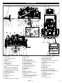
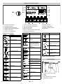
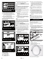
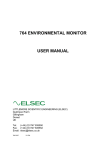
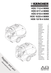
HD 7/250 De Tr1 59633200 08/10 2 Please read and comply with these original instructions prior to the initial operation of your appliance and store them for later use or subsequent owners. Contents – – – Safety instructions EN - 1 Function EN - 2 Environmental protection EN - 2 Proper use EN - 2 Device elements EN - 3 Operation EN - 5 Frost protection EN - 8 Maintenance and care EN - 10 Faults EN - 14 Technical specifications EN - 16 Accessories and Spare Parts EN - 17 Warranty EN - 17 CE declaration EN - 17 – – – – – – Safety instructions Hazard levels Danger Immediate danger that can cause severe injury or even death. 몇 Warning Possible hazardous situation that could lead to severe injury or even death. Caution Possible hazardous situation that could lead to mild injury to persons or damage to property. – – Safety instructions Danger – – – – – – This appliance must only be operated, maintained and repaired by authorised, skilled and trained personnel. Only physically and mentally fit and reliable people should operate and care for this high pressure water jets (minimum age 18). The operator or his representative must be certain that the operator is familiar with the appliance and its application and that he will be able to perform the assigned tasks responsibly. Fatigue, health issues, influence by alcohol or medications lead to a higher safety risk while operating the machine. For safety reasons, a second person must always be present when the appliance is being operated, in order to be able to shut off the appliance in emergencies and to summon help if needed. The local and relevant accident prevention directives as well as other, generally applicable safety, health and work related regulations are to be observed. The user is obliged to only operate the appliance while it is in flawless condition. – – – – – – – Safety features on the appliance and the spray unit must never be removed, modified to made inoperable. Only use hose lines, spray units and accessories approved for the maximum working pressure of the appliance. Hoses, pipes and connected accessories must be in good condition and installed properly. The application should not be operated in explosive environments. If the appliance is used in hazardous areas (e.g. filling stations) the corresponding safety provisions must be observed. During jet spray work, nobody besides the operator is allowed in a radius of 10 m around the spray unit. Never direct the water jet on to persons, animals, the appliance itself or electrical components. Modifications of the set operating over pressure on the appliance may only be performed if previously agreed with the operator of the spray unit. Risk of injury! The recoil pressure of the spray pipe can throw you off-balance. You may fall. The spray jet can fly off and cause damage to persons. Search a secure place to stand and hold the gun firmly. Never hold on tightly to the lever of the hand spray gun. Risk of falling! Take precautions when working on a scaffold, so that the person does not fall from the scaffold due to the recoil force generated by the appliance. For manual work with a spray gun, the nozzle diameter must be selected so that the recoil force in the longitudinal axis does not exceed 250 N during max. operating pressure. If the recoil force 150 N, the spray gun must be equipped with a body support as per European standard prEN 1829. With recoil forces that exceed 250 N, the nozzle must be guided mechanically.+ The recoil forces may be different if you are using angular spray devices. Always monitor the displays during operation. If the displayed values are not correct, switch the appliance off immediately and remediate the cause of the malfunction. If the appliance is not to be turned on, e.g. during maintenance procedures, you must attach a warning sign on the switch cabinet. Prevent unauthorised personnel from using the appliance by switching off the key switch and removing the key. The appliance must be secured against unauthorised use during work breaks. If the water stream is directed on sound-amplifying objects, the noise emission values may exceed the values listed in the specifications. Any type of non-adherence as well as resulting injuries to humans and damage to materials lies in the responsibility of the operator. Failure to observe these warnings may result in injuries or death of the operating personnel. EN - 1 Protective clothing Danger When working with the appliance or when being present near the spray unit, the following protective clothing must be worn: Helmet with protective shield Safety goggles Capsule ear protection Protective gloves Special safety boots and a middle foot protection Protective jacketprotective overalls Note You must use protective clothing that is specifically intended to be used with high pressure cleaners. Effective protective clothing can be purchased directly from KÄRCHER. Safety Devices Safety devices serve to protect the user and must not be rendered inoperational or their functions bypassed. Emergency-stop button To put all functions out of operation immediately: Press emergency-stop button. The appliance is free of pressure. Safety switch for appliance hood The appliance should be used only if the appliance hood is closed. If the appliance hood is opened during operation, the appliance will switch off and a fault will be displayed. 3 Burst disc If the working pressure exceeds the max. permissible overpressure by approx. 10%, the burst disc will be destroyed and the water will circulate inside the appliance without pressure. High pressure operation no longer possible. Pressure switch The pressure switch switches off the appliance if the minimum prepressure is not reached. High pressure sensor The pressure sensor monitors the pressure buildup in the high pressure system. If the pressure sensor detects an exceedingly rapid pressure decrease, as might be the case with leaks or a burst hose, as well as if the working pressure is exceeded, the appliance will shut off. Warning and instructive signs Danger Risk of injury on account of electric shock! 몇 Warning Risk of burns on account of hot surfaces! 몇 Warning Danger of crushing. Do not remove the cover while the appliance is running. Do not reach near the cooling fan and the Vbelt while the motor is running. Î Retighten the wheel bolts and the wheel nuts after driving 50 km to a torque of 100 Nm. Î Repeat the check after 500 km have been driven and after 50 operating hours. Î Repeat the safety checks at regular intervals. Î Have the brake system and the lighting system checked regularly by an authorised dealer workshop. Keep the warning and instructive signs on the appliance clean. Replace damaged or missing warning and instructive signs with new ones. Function Proper use The high pressure pump is driven by an intermediate gear by a diesel motor. When the jet operation is interrupted, an electric signal will switch the system from hand spray gun to pressureless water circulation. The preset operating pressure is regulated via the motor speed. Use this appliance only as directed in these operating instructions. – The appliance is used to clean objects by means of a high pressure water jet with cold water without the use of detergents. – The appliance may only be equipped with original accessories and spare parts. – The appliance is not suited for the use in potentially explosive environments. – The appliance is not suitable to be used simultaneously with multiple spray units. – The fresh water supply must meet the following requirements: Environmental protection Please arrange for the proper disposal of the old appliances Old appliances contain valuable materials that can be recycled; these should be sent for recycling. Batteries, oil, and similar substances must not enter the environment. Please dispose of your old appliances using appropriate collection systems. Please make sure that engine and gear oil, diesel and antifreeze do not enter the environment. Protect the ground and dispose of used oil as well as fuel and antifreeze in an environmentallyclean manner. Please do not release mineral oil containing wastewater into the soil, surface waters or sewer systems. Notes about the ingredients (REACH) You will find current information about the ingredients at: http://www.karcher.de/de/unternehmen/ umweltschutz/REACH.htm Furthermore, the personnel must participate in a Kärcher safety seminar. 4 EN - 2 max. temperature pH value Total hardness max. iron max. manganese max. chloride max. organic substances 60 °C 6,5...12 3...30 °dH 0.2 mg/l Fe 0.05 mg/l Mn 100 mg/l Cl 12 mg/l KMnO4 use max. sulphate 100 mg/l SO4 max. chlorine 0,5 mg/l Cl2 min. dissolved oxygen 5 mg/l O2 max. abrasive hazardous 5 mg/l substances free of undisolved gases max. conductivity 1000 µS/cm remaining values as per DIN 50930 Device elements 1 2 3 4 5 6 7 8 9 10 11 12 13 14 15 16 17 18 19 Towing hitch Tear-off rope Connector vehicle lighting Support wheel Battery Battery main switch Block wedge Oil dip pump gear Covering lid, oil drain opening pump gear Oil drain screw intermediate gear Oil sight glass intermediate gear Ventilation screw intermediate gear Ventilation end gear Filling nozzle diesel tank Compressor Cover Compressed air valve Air filter Equalising reservoir motor coolant 20 21 22 23 24 25 26 27 28 29 30 31 32 33 34 35 36 Radiator Parking brake Cover Door operating panel Lock of appliance hood Safety support appliance hood Registration plates Storage compartment Hinge, storage compartment Emergency-stop button Switch box Operating field Vice Socket, control line Exterior air connection (supply) Water inlet Right compressed air connection, to connect a compressed air tool 37 Hose sock mounting EN - 3 38 Left compressed air connection, to connect a compressed air tool 39 High-pressure outlet 40 Lifting eyelet (option) 41 Drain tap of the water tank (inside the appliance) 42 Ball tap, antifreeze/water tank 43 Main fuse 44 Antifreeze container 45 Switch valve 46 Pump head 47 Maintenance door water tank 48 Pressure sensor/high pressure 49 Maintenance unit, pneumatics (cyclone separator) 50 Manometer compressed air 51 High pressure pump 52 Waterfilter 53 Filler neck motor oil 5 Display and operating panel + 8 1 2 3 4 5 6 Display actual pressure Bar graph fuel level Bar graph water level in tank Display cooling water temperature Display oil pressure F6 key, menu preselection Symbols on the display Symbol Meaning Nominal pressure Actual pressure Motor oil pressure Fuel level Water level in tank 7 8 9 10 11 12 7 Key F5, increase nominal value Key F4, decrease nominal value Key F3, motor OFF Key F2, motor ON Key F1, reset key (acknowledge fault) Display appliance status Symbol Meaning Change value 13 14 15 16 Display operation Display actual speed Display nominal pressure Key switch Symbol Meaning Antifreeze rinse operation Brightness and contrast settings Load control Informational display for service personnel (inputs/outputs, operating and high pressure hourmeter) List of faults Display OK (control voltage ON or motor is running) Display wait time Preglowing (hold for 3 seconds) Confirmation Nominal pressure reached Cool water temperature Triggering outputs Reset High pressure hours The symbols of the fault displays are described in the Chapter "Faults". Hand spraygun Operating hours of motor Motor ON Motor OFF Service interval hours motor Service interval hours pump Fault code motor Reduce nominal value Gun operation Increase nominal value Menu preselection 6 Gun operation with speed stop EN - 4 1 2 3 4 5 Coupling of the control cable Lever Locking High pressure hose connection Spray pipe connection Operation Please observe Chapter "Safety Instructions" and the enclosed safety instructions for high pressure cleaners (5.063-314.0) Î Remove the chocks from underneath the wheels and place them in their holders. Î Release parking brake. Transport Trailer operation Note The driver, who operates the towing vehicle with trailer on public roads must ensure that he has the appropriate license for this. Danger When transporting the trailer in public traffic with the water tank half full, the water can swap out or the trailer could even tilt during extreme steering manoeuvers. Î Completely fill or empty the water tank. Do not transport with the water tank half full. Î Close the appliance hood and openings. Î Adjust the height of the drawbar by means of the support wheel to the height of the trailer hitch of the towing vehicle. Î Attach the tear-off rope to the towing vehicle. Preparing for start-up 1 2 3 4 5 6 Third brake light Combined brake/tail lights, right, left Blinker, right/left Reverse light License plate lighting Fog lamp Î Check the brake lights, blinkers, tail lights, reverse lights, fog lamp and the license plate lighting for their function. Î Check tire pressure (refer to technical data). Note Local speed limits for vehicles with trailers must be observed and adhered to. Loading The appliance must be fitted with lifting eyelets (option) to be raised by means of a crane. The appliance should only be lifted by the lifting eyelets. 1 2 Coupling lever Bolt with marking Setting up the appliance Î Hitch up the towing vehicle. Make sure that the marking on the bolt points to the + symbol (Pfeil) once the coupling lever is pushed down. Î Connect the connector of the vehicle lighting. Î Rotate the support wheel up by means of the crank. Check the fill levels Î Open the lock on the appliance cover and swivel the appliance cover upwards. Î Swivel the latch of the appliance hood upwards to keep it from shutting inadvertently. Î Align the appliance horizontally Check oil level in the pump, intermediate gear and motor Î Unscrew the oil dip on the pump gear. Î Wipe the oil dip with a lintfree cloth. Î Reinsert the dip completely and pull it back out. Î If the oil level has sunken to the mark, refill oil (see "Care and Maintenance"). Î Check the oil level in the intermediate gear. Î The oil level must be in the centre of the viewing glass. If this is not the case, refill oil (see "Care and Maintenance"). Î Pull out the oil dip of the motor. Î Wipe the oil dip with a lintfree cloth. Î Insert the oil dip, pull it out and read it. Î If the oil level has sunken to the mark, refill oil (see "Care and Maintenance"). Check the fill level of the coolant in the motor Î Check the fill level of the coolant in the equalisation container of the motor coolant with a cooled off motor. The liquid level has to be between MIN and MAX. Check the fill level of the antifreeze Î In case of risk of frost, unscrew the lid of the antifreeze container and check the fill level. If required refill antifreeze. Turning on the Appliance Î Switch on the battery main switch. Î Switch on the key switch on the operating panel. 1 2 3 4 5 Î Make sure that the suppport wheel points in the direction of the trailer when retracted. Î Disconnect the connector from the vehicle lighting and insert it into the plug storage on the drawbar. Î Secure the machine with wheel chocks to prevent it from rolling away. Î Disconnect the towing vehicle. Î Align the appliance horizontally with the support wheel. Caution Risk of malfunctions and damages to the appliance. The appliance must be in horizontal position during operation. Crank to lower the support wheel Connector vehicle lighting Tear-off rope Support wheel Parking brake Î Lock parking brake. Î Lower the support wheel by means of the crank. Î Remove the tear-off rope from the towing vehicle. EN - 5 Check the fill level of the diesel tank Danger Risk of explosion, fire, poisoning by means of exhaust gases. – Turn the motor off prior to fueling up. – Do not refuel in closed rooms, ensure sufficient ventilation. – Never fill up in the vicinity of open flames or sparks. – Do not smoke during fueling. – Immediately remove fuel that leaked during the refuelling with cleaning cloths and dispose of it properly. 7 Caution Do not completely deplete the fuel in the fuel tank, otherwise, the fuel system will have to be ventilated. Possibly suctioned dirt from the bottom of the tank can lead to malfunctions. Î Check the fill level of the diesel fuel at the bar segment display for the fuel level. If required, top off the diesel fuel. For temperatures below 0°, only use winter diesel. Check the fill level in the water tank Î Check the fill level of the water at the bar segment display for the water level in the tank. Top off the water tank if necessary. Connect the water supply hose to the water inlet. Start up Connecting the spray pipe to the gun 1 2 3 4 5 6 Trigger gun Pressure ring Pressure screw Spray lance Nozzle holder High pressure nozzle Î Remove the protective caps on the spray pipe. Î Grease the thread on the gun side with stainless steel screw grease (6.280180.0). Î Screw the pressure ring onto the spray pipe. A B Î The sealing cone of the spray pipe must protrude about 1-1.5 thread lengths (B) from the pressure ring (A). Î Rotate the pressure ring (A) by hand to adjust the distance (left thread). Î Insert the spray pipe all the way into the gun. Î Secure the spray pipe by tightening the pressure screw (torque approx. 100 Nm). Connecting the nozzle Do not perform this procedure until after the unit has been ventilated, see "Ventilating the high pressure system“. Î Grease the thread on the nozzle side with stainless steel screw grease (6.280-180.0). 8 Î Grease the nozzle holder with stainless steel screw grease (6.280-180.0) and screw it onto the spray pipe (left thread). Î Grease the thread of the high pressure nozzle with stainless steel screw grease (6.280-180.0) and screw it onto the nozzle holder (hexagon socket). Connect the high pressure hose to the gun and the appliance. Danger Risk of injury from leaks or water jets emerging from leaks. – Hoses, pipes and the spray unit must be in good condition and installed properly. – Check the high pressure hose daily. – Only use original high pressure hoses that are approved for the respective pressure range and temperature. – Avoid contact with chemicals. – Do not use hoses with kinks. – Do not use the high pressure hose anymore if the thread is damaged or corroded. – Stop using the high pressure hose if the external wire layer is visible. – Do not route the high pressure hose across sharp edges. – Lay the high pressure hoses in such a way that no vehicle can drive over it. – Do not use high-pressure hoses that have been driven over, kinked, pressed or bent even if there is no externally visible damage. – Completely lay out the high pressure hose, do not overlap. – High pressure hoses age with time. Replace high pressure hoses every 6 years, even if they are in good condition. – High pressure hoses that have been stored for more than 2 years, may no longer be used. – Store the high pressure hose so that there is no mechanical strain. Store in a cool, dry and dustfree place. – Do not stretch the high pressure hose during storage, as the high pressure hose might change its length during operation. – Relieve tension from the high pressure hose after operation, purge excess water, coil it and store it properly. Î Unscrew the protective caps from the high pressure connection of the hand spray gun and pull off at the high pressure hose. Î Clean the thread and grease it with stainless steel screw grease (6.280180.0). Î Check the high pressure hose for flawless condition (no damage). Only use intact hoses. Î Connect the high pressure hose to the hand spray gun (procedure as described in Chapter "Connecting the spray pipe to the gun"). Î Remove the protective cap from the high pressure outlet of the appliance. EN - 6 Î Clean the thread and grease it with stainless steel screw grease (6.280180.0). Î Connect the high pressure hose to high pressure connection (procedure as described in Chapter "Connecting the spray pipe to the gun"). 1 2 Hose sock mounting Hose sock Î When using a hose sock to protect the high pressure hose from ripping off, hook the hose sock into the hose sock mount. Connect the control line Î Roll the control line off the winch to hose length. Make sure that the control line is not underneath the high pressure hose, as the high pressure hose can rub against it and cause a line break. Î Pull of the protective cap or antifreeze plug on the appliance connection side. Î Connect the short cable end of the winch with the socket. Î Plug the protective caps together to prevent soiling of the protective cap insides. Î Connect the control line on the gun side and plug the protective caps together. Connect the water supply According to the applicable regulations, the appliance must never be used on the drinking water net without a system separator. Use a suitable system separator manufactured by Kärcher; or, as an alternative, a system separator as per EN 12729 Type BA. Note Water with drinking water quality with a pressure between 0.15 and 0.6 MPa (1.5 to 6 bar) is required to ensure a smooth operation of the system. Î Remove the protective cap from the water supply inlet of the appliance. Î Connect the system separator to the water inlet (option). A If the system separator was installed, the water inlet is on the appliance B Water inlet on the system separator Î Connect the water supply hose to the respective water inlet (arrow). Î Open the lock on the appliance cover and swivel the appliance cover upwards. Î Swivel the latch of the appliance hood upwards to keep it from shutting inadvertently. Î Check the water filter for contamination, clean/replace if required. Î Switch off the motor. Î Install the nozzle as described in the chapter "Connecting the nozzle". Settings + 8 7 The control voltage is switch on and the display shows the operating status. Adjust the water pressure Note The water pressure can be changed right after startup with the key switch as well as during operation. Î Adjust the water pressure using the F5 and F4 keys "Increase/reduce water pressure". The water pressure can be changed in increments of 5 MPa (50 bar). Î Check the position of the ball tap in the antifreeze/water tank, set to the water tank on the right. Î Close the drain tap of the water tank. At low ambient temperatures, the preheating process will start automatically. The respective message is shown on the display. Î Press the F2 key to start the motor. Motor runs warm. The set water pressure has been reached. Adjust the brightness and contrast of the display + 8 Î Switch on the battery main switch. Î Tilt the safety latch of the appliance hood toward the bottom. Î Tilt the appliance hood downward and lock it. Î Open the door to the operating panel and switch on the ignition via the keyswitch. If the tank level is low, the water will be supplied During the warm up time, the display will show the clock symbol. 7 Î Step 1: Press F6 key. MENUE Start the engine Note The appliance can only be operated with the appliance hood closed. The appliance will switch off when the appliance hood is opened. Î Release emergency-stop button by turning. Î Open the operating panel door. Î Turn the key switch to the right. Î Step 2: Press F4 key. After the warm up time, the appliance will be ready for high pressure operation. Ventilating the high pressure system Î Connect the high pressure hose, gun and the spray pipe without nozzle as described in chapter "Startup". Î Activate the gun about 30 to 40 seconds until a continuous water jet is emitted from the spray pipe. EN - 7 9 Î By pressing the F6 key twice, you will return to the operating display. 0 ___ 155 ___ 210 Î Step 3: Press the F3 key to switch between brightness and contrast. Î You can change the brightness and contrast levels with the F4 and F5 keys. F4 (-) = set value decreases. F5 (+) = set value increases. Î By pressing the F6 key twice, you will return to the operating display. Retrieve the informational display for service personnel + Operation 100 Note If the appliance is protected with antifreeze, this antifreeze must be purged from the water system (see chapter "Pumping antifreeze out of the water system“). Remove air from the high pressure system prior to operation! Î Press the release of the hand spray gun downwards. Î Pull the lever on the handgun toward the back. The motor goes to operating speed. The high pressure water stream is released. Î To switch off the high pressure spray, release the lever of the hand spray gun and let the release lock. Note Frequent switching on and off of the high pressure spray increase the wear and tear on the appliance and reduce its product life. Perform the cleaning process with as few interruptions as possible. Shutting down 8 7 Î Step 1: Press F6 key. MENUE Note Only use the Emerg Stop key in emergencies, not to switch off the appliance. A frequent use of the emergency stop key will increase wear and tear on the appliance. Î To switch off the high pressure spray, release the lever of the hand spray gun and let the release lock. Î Press F3 key. Depending on the load, the motor should somewhat longer to cool off. Î If there is a risk of freezing temperatures during the operational break, flush the appliance with antifreeze (see Chapter "Antifreeze") or transport the appliance to an area protected from frost. Î Turn main key to "0" and remove it. Î Close and lock the operating panel door. Î Open the hood and remove the key from the battery separating switch. Î Unscrew the high pressure hose, the water supply hose and the control line. Î Protect the hose connections and couplings from contamination with protective caps. Note Do not store any objects (incl. hoses, cables and spray units) inside the appliance. Use the storage compartment or storage box (option) to store these items. Frost protection Note Use commercially available glycol-based antifreeze for automobiles. Observe the manufacturer's handling instructions. To protect from freeze damages, the appliance must be flushed with antifreeze. – Antifreeze flushing in a circuit from the antifreeze tank of the appliance, for preferred use on site Antifreeze rinse in the circuit (high pressure pump) 5 4 3 1 1 2 Î Step 2: Press F3 key. The display will show the trailing time of the motor with the clock symbol. + 10 Maintenance door water tank Ball tap, switchover antifreeze/water tank Backflow antifreeze Antifreeze container filler neck Drain tap water tank 8 Different parameters can be read in the informational display: U = operating voltage RPM = motor speed bar = operating pressure h = operating hours 3 4 5 2 7 The motor will switch off. EN - 8 1 Antifreeze hose Î Unpressurize the appliance. Î Refill the antifreeze container with antifreeze. Select the mixing ratio of the water/antifreeze as per the instructions of the antifreeze manufacturer. Î Align the actuation lever of the ball tap for antifreeze/water tank vertically. Î Unscrew the high pressure hose from the high pressure outlet. The control voltage is switched on and the display shows the antifreeze rinse operation. Î Press the F2 key to start the motor. Î Let the motor run until antifreeze is visible in the antifreeze hose. The antifreeze liquid is pumped through the appliance in a circuit. Note After each antifreeze flush, the antifreeze concentration must be tested in the hose with a commercially available antifreeze tester in the return flow from the hose. Add more antifreeze as needed if the concentration is too low. Î Press the F3 key to shut off the motor. Wait for the motor to stop trailing. Î Remove the antifreeze hose between the high pressure outlet and the antifreeze return. Î Connect the antifreeze hose between the high pressure outlet and the antifreeze return. Î Create a water supply connected to the system separator. Î Turn the key switch to the right. The control voltage is switch on and the display shows the operating status. The solenoid valve for the water supply will open. Antifreeze motor Î Check the coolant circuit of the motor for sufficient antifreeze, refill antifreeze as needed. See Maintenance Procedures "Check and refill the coolant“. Battery Î Connect the antifreeze hose between the high pressure outlet and the antifreeze return. Î If the appliance is not used for an extended period and if there is frost, remove the battery and store it in a location protected from frost. Pumping antifreeze out of the high pressure system Note Prior to operation, the antifreeze must be pumped from the high pressure system back into the antifreeze container. Î Unpressurize the appliance. Î Plug in the antifreeze plug control line. Î Turn the key switch to the right. Î Plug in the antifreeze plug control line. Î Press the F2 key to start the motor. Î The antifreeze liquid is routed into the antifreeze tank with fresh water from the fresh water reservoir. Î Rinse for about 2 minutes. Watch the antifreeze hose until no more antifreeze can be seen. Î Press the F3 key to shut off the motor. Wait for the motor to stop trailing. Î Remove the antifreeze hose between the high pressure outlet and the antifreeze return. Î Swivel the actuation lever of the ball tap for antifreeze/water tank to the right. EN - 9 11 Maintenance and care – Danger – – 1 2 3 4 5 6 7 8 9 10 11 12 13 14 15 12 Maintenance Procedures may only be carried out by persons who have been instructed in the safe operation and maintenance on the high-pressure systems. Before carrying out any tasks on the machine, switch the key switch off and remove it. Prevent inadvertent startups of the appliance during Maintenance Procedures via third persons by attaching signs on the appliance and the spray unit. – – – If the appliance must be started up for maintenance procedures, a second person must be present for safety reasons. Water under high pressure can penetrate the skin and cause severe injuries and infections. Stay away from leaks and do not search for leaks by hand. Do not use flammable detergents to clean the appliance. After completing the maintenace work, check all safety devices for correct installation and proper function. Waterfilter Filter pot Filter inlay Ventilation of pump gear Ventilation screw intermediate gear Oil sight glass intermediate gear Oil drain screw intermediate gear Oil drain screw pump gear Oil dip pump gear Air filter Air filter insert Cover Lock Battery Filler neck motor oil EN - 10 몇 Caution Risk of damage. Do not disconnect the battery while the ignition is on or the motor is running. Flow pattern 1 2 3 4 5 6 7 8 9 10 11 12 13 14 15 16 17 18 19 20 Compressor Oil cooler module Air cooler module Cyclone separator 2/2 way solenoid valve, 2-stroke Condensation drain, return to water tank Pressure relief valve Silencer Backflow valve Pressure regulation valve Ball tap Safety valve Pressure container Compressed air filter Pressure switch 2/2 way PN bypass valve 5/2 way valve 3/2 way valve Burst disc safety High pressure sensor 21 22 23 24 25 26 27 28 29 30 31 32 33 High-pressure pump Internal combustion engine Prepressure manometer Advance pressure pump Ball tap Water reservoir Antifreeze tank 2/2 way solenoid valve High-pressure outlet Exterior air Quick coupling Water filter Fill level probe EN - 11 13 Maintenance intervals Time Prior to each drive Activity Check the lighting. Check the tyre pressure and their state. Every 10 operating Check oil level in the pump gear (see "Initial startup"), refill oil if needed. hours or daily Check the water filter and clean if necessary. Check coolant level in the equalisation container (see "Initial startup"), refill coolant if needed. Once after the first 50 Replace motor oil (see "Maintenance Procedures"). operating hours Replace oil filter insert on motor. Check the screw connections on the motor. Call customer service if necessary. Once after the first 150 Replace oil in the pump gear. operating hours Replace oil in the intermediate gear. Every 50 operating Check pipes to see if there are any leaks. hours or weekly Check the V-belt tension, retension if necessary (see "Maintenance Procedures"). Check/clean the air filter insert (see "Maintenance Procedures"). Customer Service Customer Service Customer Service Customer Service Customer Service Operator Customer Service/ Operator Customer Service/ Operator Operator Check the screw connections on the motor. Call customer service if necessary. Replace motor oil (see "Maintenance Procedures"). Replace oil filter insert on motor. Replace the fuel filter. Cleaning the water separator. Lubricate the brake on the drawbar (see "Maintenance Procedures"). Customer Service Customer Service Customer Service Customer Service Customer Service Operator Replace air filter insert (see "Maintenance Procedures"). Replace V-belt. Check the injection pressure at the fuel injector nozzle. Customer Service Customer Service Customer Service Check hoses for wear, replace if required. Every 100 operating hours Every 200 operating hours Every 400 operating hours After 750 operating hours or once a year Every 1500 operating hours Every 3000 operating hours Every other year By whom Operator Operator Operator Operator Operator Replace oil in the pump gear. Replace oil in the intermediate gear. Check the coolant in the motor and replace (see "Maintenance Procedures"). Maintenance Works Check the oil level on the motor and add motor oil Note Only trained personnel is permitted to add motor, gear and pump oil. Note Align the appliance horizontally prior to check the oil level in order not to get a false result. Check the oil prior to starting the appliance or at least 5 minutes after switching off the engine. Caution Increased risk of fire! When filling the motor oil make sure that no oil lands on hot motor surfaces. Î Remove the oil dip, wipe it and reinsert it. Î Remove the oil dip one more time and check the oil level. Î Î Î Î The oil level is correct if it is within the markings (arrows) on the oil dip. Customer Service Customer Service Customer Service/ Operator Wait five minutes, until the oil has collected in the oil pan. Check the oil level as described above. Repeat this procedure as often as necessary until the oil level is between the markings on the oil dip. After the check, insert the oil dip and close the lid of the filler neck. Oil change (to be performed by customer service only) Note Only trained personnel is permitted to add motor, gear and pump oil. Note Replace the oil while the motor has operating temperature. Align the appliance horizontally prior to the oil change. Motor Above 25 °C 0 °C to 25 °C Î If the oil level is below the bottom mark, open the filler neck lid (arrow) and add fresh motor oil. 14 EN - 12 Below 0 °C SAE30 or SAE10W-30 SAE 15W-40 SAE20 or SAE10W-30 SAE 15W-40 SAE10W or SAE10W-30 SAE15W-40 Pump and gear Pump Mobil D.T.E Oil AA 320 Gear Mobil D.T.E Oil AA 320 Î The oil level is correct if it is within the markings on the oil dip. Î After the check, insert the oil dip and close the lid of the filler neck. Check the coolant and refill Note Prior to every operation, the fill level of the coolant in the equalisation container must be checked. Caution Observe the brand of antifreeze used. The mixture can cause a chemcial reaction and hazardous substances can be generated. Do not mix different antifreeze types. 몇 Warning The motor can overheat if there is a lack of coolant. Turn the motor off immediately and let it cool down. If the motor is so overheated, that water vapors escape, immediately turn the motor off and keep a safety distance to the motor until the pressure has decreased. Danger of burns! Never open the lid on the cooler while the motor has operating temperature. The container is under pressure. Î Open the lid on the equalisation container of the motor coolant, fill in fresh clean water and the required antifreeze. Î Blow out the filter insert with compressed air (max. 2 bar) from the inside. Î Clean the inside of the air filter housing with a cloth. Note Severely contaminated or defective filter inserts must always be replaced. Î Please the filter insert into the air filter housing with the closed side facing out. Note Make sure the lid fights snugly, if the lid does not close properly, dust can get into the combustion chamber of the motor and damage it. Î Replace the lid and close the locks. Draining the compressed air system Note The compressed air system must be drained in regular intervals. During continuous operation, it might be necessary to drain it 2 to 3 times a day. Note Do not drain the liquid from the system during high pressure operation. If the ball tap is open, pressure cannot be built up in the compressed air lines. Cleaning/replacing the air filter Î Open the ball tap. Allow the water to drain. Î After the drain procedure, close the ball tap. Î Open both locks (arrows) on the lid. Î Remove the lid and the dust sediments. Î Take out the filter inlay. Compressor Note Maintenance work on the compressor may only be performed by the authorised customer service. Charge/replace battery 몇 Warning Battery acid is very corrosive! Always wear acid-resistant goggles, gloves and an apron when working with battery acid. Never charge the battery in the vicinity of open flames or igniting sparks. The battery may only be charged in rooms that are sufficiently ventilated. Depending on the battery type, the acid level might need to be checked. The motor must be turned off to charge the battery. Note Prior to connecting the charger, the connecting cables to the control must be disconnected from the battery. Otherwise, the control could be damaged! If the appliance is not used for an extended period and if there is frost, remove the battery and store it in a location protected from frost. EN - 13 몇 Warning Never connect frozen batteries to charge them. Risk of explosion! Prior to charging, thaw the battery and warm to at least 16 °C. Note When disconnecting the battery, first disconnect the negative and then the positive terminal. When reconnecting the battery, first connect the positive and then the negative cable. Do not transpose the connecting cable. Risk of cable fire! Î Disconnect the connecting cable from the battery at the negative terminal. Î Disconnect the connecting cable from the battery at the positive terminal. Î Connect the charger. Î Disconnect the charger after the charging process is complete. Î Connect the connecting cable to the positive terminal on the battery. Î Connect the connecting cable to the negative terminal on the battery. Checking the V-Belt Note If the V-belt is not sufficiently tensioned, this can cause an overheating of the motor or to an insufficient battery charge. Î Shut off the motor and remove the key from the key switch. Î To check whether the V-belt is tensioned, press the belt with your thumb. If the V-belt can easily be deflected, or if it sits loosely on the pulleys, you must order authorised customer service to tension/replace the V-belt. Note Defective V-belts must be replaced immediately. Caution The V-belt must only be tensioned or replaced by Customer Service. Lubricate the brake on the drawbar Î Press lubricant into both lubrication nipples (arrows) using a commercial grease press. 15 Î Read the fault message on the display and remediate the fault as per the table below. Î Press the reset button to acknowledge/ confirm the fault message. Faults Danger This can lead to severe injuries and possibly death. An improper startup and repair of the appliance and the spray unit is dangerous. Faults with display Faults detected by the control are shown on the display. 1 2 3 Display/meaning >Malfunction< EMERGENCY STOP Display Fault indication Reset key to confirm the fault Cause Emergency Stop switch depressed Remote control not connected Plug wet Plug defective Switch in the hand spray gun defective Cable breakage Remedy Unlock Emergency Stop switch Create connection Dry the plug Replace the plug Check the switch, replace Replace the cable By whom Operator Operator Operator Customer Service Customer Service Customer Service Device hood open Cable breakage Safety switch for appliance hood defective Close appliance hood Replace the cable Check safety switches. Operator Customer Service Customer Service Fuel tank empty. Level sensor defective Cable breakage Refill diesel fuel Replace level sensor Replace the cable Operator Customer Service Customer Service >Malfunction< Hood open >Malfunction< Tank level >Malfunction< Cooling water level >Malfunction< Motor oil pressure See motor operating instructions Level of coolant too low Refill cooling water Radiator contaminated Clean the radiator V-belt tension on the ventilator too low Retension V-belt Thermostat defective Replace the thermostat Cable breakage Replace the cable Motor oil level too low Check the motor oil level Oil the motor has the wrong viscosity Replace engine oil. Oil pressure switch on motor defective Replace oil pressure switch on motor Cable breakage Replace the cable Look for more instructions in the motor's operating instructions Coolant level in the motor too low Radiator contaminated V-belt tension on the ventilator drive too low >Malfunction< Motor temperature >Malfunction< Tyre pressure 16 Check coolant units Clean the radiator Check V-belt tension Tighten V-Belt Thermostat defective Check thermostat Defective temperature switch Check the temperature switch Cable breakage Replace the cable Look for more instructions in the motor's operating instructions Ball tap of drain open Close the ball tap Water in the compressed air tank Drain water Air system leaks Seal the air system Compressor defective Repair the compressor V-belt tension on the compressor drive too low Tighten V-Belt Pressure switch is defective Check/replace the pressure switch Cable breakage Replace the cable EN - 14 Operator Operator Customer Service Customer Service Customer Service Operator Customer Service Customer Service Customer Service Operator Operator Operator Customer Service Customer Service Customer Service Customer Service Operator Operator Customer Service Customer Service Customer Service Customer Service Customer Service Display/meaning >Malfunction< High pressure sensor Cause Cable plug of high pressure sensor loose or short in connection Cable breakage High pressure sensor defective Remedy Check for correct fit By whom Operator Replace the cable Check / replace the sensor Customer Service Customer Service The permitted max. pressure is exceeded due Check the nozzle size, install correct noz- Operator to small or plugged nozzle zle Load speed too high Reduce load speed Customer Service >Malfunction< High pressureHochdruck > max. Check the switch valve Customer Service Replace the cable Check the high pressure valve Check / replace the sensor Customer Service Customer Service Customer Service Check the inlet valve to the water tank Operator Use a water supply hose with a larger cross section >Malfunction< Level switch defective Replace the level switch Water level Cable breakage Replace the cable Water reservoir empty Filling the Water Reservoir Water filter contaminated Clean water filter Backflow valve on the advance pump contami- Check backflow valve nated >Malfunction< Pressure switch is defective Check/replace the pressure switch Water inlet pressure Cable breakage Replace the cable below 0.15 MPa (1.5 Advance pump defective Check / replace the prepressure pump bar) Advance pump drive defective Check/replace the main switch Remote control not connected Create connection Plug wet Dry the plug Plug defective Replace the plug Switch in the hand spray gun defective Check the switch, replace >Malfunction< Cable breakage or short in the control line Check the cable, replace Remote control See motor operating instructions Evaluation unit defective Replace evaluation unit Cable breakage Replace the cable Operator >Malfunction< High pressure decrease too slow The pressure decrease is too slow after the lever of the hand spray gun is released Cable breakage High pressure valve defective High pressure sensor defective Water tank empty. Inlet valve to water tank closed (by customer) Cross section of water supply hose too small Customer Service Customer Service Operator Operator Customer Service Customer Service Customer Service Customer Service Customer Service Operator Operator Customer Service Customer Service Customer Service Customer Service Customer Service >Malfunction< EMR fault Oil temperature too high Temperature sensor defective Cable breakage Check the oil temperature Replace the temperature sensor Replace the cable Operator Customer Service Customer Service See motor operating instructions Water in fuel Cable breakage Replace the fuel Replace the cable Operator Customer Service >Malfunction< Compressor temperature >Malfunction< Water in fuel EN - 15 17 Faults without display on the console 1 Fault Appliance stops, display switches off No display after switching the appliance on Main fuse Cause Main fuse is blown Remedy Replace the main fuse Battery main switch switched off Switch on the battery main switch Battery depleted Charging battery Main fuse is blown Replace the main fuse Motor will not start or See separate operating instructions of the motor turns off immediately Working pressure is Air in the high pressure pump Ventilating the high pressure system fluctuating Valves worn out Replace the valves By whom Operator Operator Operator Operator Operator Customer Service Technical specifications HD 7/250 DE TR1 Water connection Max. feed temperature Min. feed volume Feed pressure Performance data Water flow rate Operating pressure of water (using standard nozzle) Max. excess operating pressure (safety valve) Drive motor performance Motor rpm Battery Nozzle size Max. recoil force of hand spray gun Fuel Oil quantity, intermediate gear Öl type, intermediate gear Oil quantity, pump gear Oil type, pump gear Oil quantity, motor Öl type, motor Content of cooling system Dimensions and weights Length x width x height Diesel tank Weight without operating materials Weight including operating materials, approx. Permissible axle load Antifreeze container Water reservoir Tyre type Tyre pressure Brake system Vibration total value (ISO 5349) Hand-arm vibration value Hand spraygun Spray lance Uncertainty K Sound pressure level LpA (EN 60704-1) Uncertainty KpA Sound pressure level LWA + Uncertainty KWA (2001/14//EC) 18 °C l/h (l/min) MPa (bar) 60 1080 (18) 0,15...0,6 (1,5...6) l/h (l/min) MPa (bar) MPa (bar) kW 1/min V/Ah 672 (11,2) 250 (2500) 300 (3000) 74 3000 12/55 0,6 129 N l l l l mm l kg kg kg l l MPa (bar) - m/s2 m/s2 m/s2 dB(A) dB(A) dB(A) EN - 16 0,6 Mobil D.T.E. Oil AA 320 4,5 Mobil D.T.E. Oil AA 320 4,5 See Maintenance tasks 10-11 4068 x 1912 x 2000 200 1240 1510 1800 25 200 205 R 14 0,45 (4,5) Overrun brake <2,5 <2,5 0,5 91 2 111 Accessories and Spare Parts – – – Only use accessories and spare parts which have been approved by the manufacturer. The exclusive use of original accessories and original spare parts ensures that the appliance can be operated safely and troublefree. At the end of the operating instructions you will find a selected list of spare parts that are often required. For additional information about spare parts, please go to the Service section at www.kaercher.com. Warranty The warranty terms published by the relevant sales company are applicable in each country. We will repair potential failures of your appliance within the warranty period free of charge, provided that such failure is caused by faulty material or defects in manufacturing. In the event of a warranty claim please contact your dealer or the nearest authorized Customer Service centre. Please submit the proof of purchase. CE declaration We hereby declare that the machine described below complies with the relevant basic safety and health requirements of the EU Directives, both in its basic design and construction as well as in the version put into circulation by us. This declaration shall cease to be valid if the machine is modified without our prior approval. Product: Maximum pressure cleaners Type: 1.025-xxx Relevant EU Directives 2006/42/EC (+2009/127/EC) 2004/108/EC 2000/14/EC Applied harmonized standards EN ISO 12100–1 EN ISO 12100–2 pr EN 1829-1 EN 1829 -2 EN 13309: 2000 EN 55012: 2007 + A1: 2009 Applied conformity evaluation method 2000/14/EC: Appendix V Sound power level dB(A) Measured: 109 Guaranteed: 111 The undersigned act on behalf and under the power of attorney of the company management. CEO Head of Approbation Authorised Documentation Representative S. Reiser Alfred Kärcher GmbH Co. KG Alfred-Kärcher-Str. 28 - 40 71364 Winnenden (Germany) Phone: +49 7195 14-0 Fax: +49 7195 14-2212 Winnenden, 2010/08/01 EN - 17 19 AE Karcher FZE, P.O. Box 17416, Jebel Ali Free Zone (South), Dubai, United Arab Emirates, +971 4 886-1177, www.kaercher.com AR Kärcher S.A., Uruguay 2887 (1646) San Fernando, Pcia. de Buenos Aires +54-11 4506 3343, www.karcher.com.ar AT Alfred Kärcher Ges.m.b.H., Lichtblaustraße 7, 1220 Wien, +43-1-25060-0, www.kaercher.at AU Kärcher Pty. Ltd., 40 Koornang Road, Scoresby VIC 3179, Victoria, +61-3-9765-2300, www.karcher.com.au BE Kärcher N.V., Industrieweg 12, 2320 Hoogstraten, +32-3-340 07 11, www.karcher.be BR Kärcher Indústria e Comércio Ltda., Av. Professor Benedicto Montenegro no 419, Betel, Paulínia - Estado de Sao Paulo, CEP 13.140-000 +55-19-3884-9100, www.karcher.com.br CA Kärcher Canada Inc., 6535 Millcreek Road, Unit 67, Mississauga, ON, L5N 2M2, +1-905-672-8233, www.karcher.ca CH Kärcher AG, Industriestrasse, 8108 Dällikon, Kärcher SA, Croix du Péage, 1029 Villars-Ste-Croix, 0844 850 864, www.kaercher.ch CN Kärcher (Shanghai) Cleaning Systems, Co., Ltd., Part F, 2nd Floor, Building 17, No. 33, XI YA Road, Waigaogiao Free Trade, Pudong, Shanghai, 200131 +86-21 5076 8018, www.karcher.cn CZ Kärcher spol. s r.o., Modletice c.p. 141, CZ-251 01 Ricany, +420/323/606 014, www.kaercher.cz DE Alfred Kärcher Vertriebs-GmbH, Friedrich-List-Straße 4, 71364 Winnenden, +49-7195/903-0, www.kaercher.de IE Kärcher Limited (Ireland), 12 Willow Business Park, Nangor Road, Dublin 12, (01) 409 7777, www.kaercher.ie JP Kärcher (Japan) Co., Ltd., Irene Kärcher Building, No. 2, Matsusaka-Daira 3-chome, Taiwa-cho, Kurokawa-gun, Miyagi 981-3408, +81-22-344-3140, www.karcher.co.jp KR Karcher Co. Ltd. (South Korea), 2nd Floor , Youngjae Building, 50-1, 51-1, Sansoo-dong, Mapo-ku, Seoul 121-060, +82-2-322 6598, www.karcher.co.kr MX Karcher México, SA de CV, Av. Gustavo Baz Sur No. 29-C, Col. Naucalpan Centro, Naucalpan, Edo. de México, C.P. 53000 México, +52-55-5357-04-28, www.karcher.com.mx MY Karcher Cleaning Systems Sdn. Bhd., 71 & 73 Jalan TPK 2/ 8, Taman Perindustrian Kinrara, Seksyen 2, 47100 Puchong, Selangor Darul Ehsan, Malaysia, +603 8073 3000, www.karcher.com.my NL Kärcher B.V., Postbus 474, 4870 AL Etten-Leur, 0900-33 666 33, www.karcher.nl NO Kärcher AS, Stanseveien 31, 0976 Oslo, Norway, +47 815 20 600, www.karcher.no NZ Karcher Limited, 12 Ron Driver Place, East Tamaki, Auckland, New Zealand, +64 (9) 274-4603, www.karcher.co.nz PL Kärcher Sp. z o.o., Ul. Stawowa 140, 31-346 Kraków, +48-12-6397-222, www.karcher.pl RO Karcher Romania srl, Sos. Odaii 439, Sector 1, RO-013606 BUKAREST, +40 37 2709001, www.kaercher.ro RU Karcher Ltd. Service Center, Leningradsky avenue, 68, Building 2, Moscow, 125315 +7-495 789 90 76, www.karcher.ru DK Kärcher Rengøringssystemer A/S, Helge Nielsens Allë 7 A, 8723 Løsning, +45-70206667, www.karcher.dk SE ES Kärcher, S.A., Pol. Industrial Font del Radium, Calle Josep Trueta, 6-7, 08403 Granollers (Barcelona), +34-902 17 00 68, www.karcher.es SGP Karcher South East Asia Pte. Ltd., 5 Toh Guan Road East, #01-00 Freight Links Express Distripark, Singapore 608831, +65-6897-1811, www.karcher.com.sg F Kärcher S.A.S., 5, avenue des Coquelicots, Z.A. des Petits Carreaux, 94865 Bonneuil-sur-Marne, +33-1-4399-6770, www.karcher.fr SK Kärcher Slovakia, s.r.o., Beniakova 2, SK-94901 NITRA, +421 37 6555 798, www.kaercher.sk FI Kärcher OY, Yrittäjäntie 17, 01800 Klaukkala, +358-207 413 600, www.karcher.fi Kärcher AB, Tagenevägen 31, 42502 Hisings-Kärra, +46 (0)31-577 300, www.karcher.se TR Kärcher Servis Ticaret A.S., 9 Eylül Mahallesi, 307 Sokak No. 6, Gaziemir / Izmir, +90-232-252-0708, +90-232-251-3578, www.karcher.com.tr GB Kärcher (U.K.) Ltd., Kärcher House, Beaumont Road, Banbury, Oxon OX16 1TB, +44-1295-752-000, www.karcher.co.uk TW Karcher Limited, 7/F, No. 66, Jhongijheng Rd., Sinjhuang City, Taipei County 24243, Taiwan, +886-2-2991-5533, +886-800-666-825, www.karcher.com.tw GR Kärcher Cleaning Systems A.E., 31-33, Nikitara str. & Konstantinoupoleos str., 136 71 Aharnes, +30-210-2316-153, www.karcher.gr UA Kärcher TOV, Kilzeva doroga, 9, 03191 Kiew, +380 44 594 7576, www.karcher.com.ua HK Kärcher Limited, Unit 10, 17/F., Apec Plaza, 49 Hoi Yuen Road, Kwun Tong, Kowloon, ++(852)-2357-5863, www.karcher.com.hk HU Kärcher Hungaria KFT, Tormásrét ut 2., (Vendelpark), 2051 Biatorbagy, +36-23-530-64-0, www.kaercher.hu I USA To locate your local dealer please visit our web site at http://www.karchercommercial.com or call us at 888.805.9852 ZA Kärcher (Pty) Ltd., 144 Kuschke Street, Meadowdale, Edenvale, 1614, +27-11-574-5360, www.karcher.co.za Kärcher S.p.A., Via A. Vespucci 19, 21013 Gallarate (VA), +39-848-998877, www.karcher.it 02/10