1
United States Patent 1191
[1 1]
4,262,248
Vincelli et a1.
[45]
Apr. 14, 1981
{54]
-
SYSTEM FOR SERVICING PROCESS
INSTRUMENTATION
Inventors: Joseph Vincelli, PiHSfOl'd; Donald P.
Persons’ Webster, both 0f NY-
['73] Assignee:
Sybron Corporation, Rochester, N.Y.
3,137,815
6/1964
Hershey ........................ .. 324/73 PC
3,657,527
4/1972
Kassabgi et a1 .............. .. 324/73 PC
Primary Examfner._Michael J‘ Tgkar
Attorney, Agent, or Firm—Theodore B. Roessel; Joseph
C‘ MacKenzle
[21] Appl. No.; 958,806
[57]
[22] Filed:
Nov. 8, 1978
An electronic circuitry servicing system having an op
erations manual setting forth servicing procedures such
"""""""""""""""
as function checking, troubleshooting, and calibration, a
3
[58} F181}: or églé'c'i‘i'ji' ...:.'::“3'§4/73 PC 158 F 73 R
' "
[56]
_
’
’
ABSTRACT
‘emp‘ate ?mng 0“ the circuit being serviced and Pm‘
viding probe access to test points of the surface and
References Clted
U,S. PATENT DOCUMENTS
graphic information about the circuit and a test ?xture
for coordinating test signals andmeasurements.
2,815,484
12/1957
Bulliett et a1. ................... .. 324/73 R
2,985,819
5/1961
Russell ............................. .. 324/73 R
3 Claims, 4 Drawing Figures
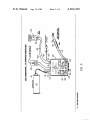
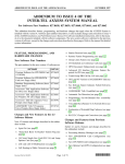
oc POWER JACKS
dc PM
To Toni-11ml‘
VOLTHE‘E“ JACKS
WVMTUWM
Timmy"
EXTERNAL CONTACT JACK
Used Only Wllh 1301mm
‘IBI'JADKA
ColluncBTohoealhputi»
MERGE IIPUI SWITCH
Cm Allnn IOINI m 1M!!!“ Scri- Instrument
nomamrmumnmurnlm
WWW-‘III’:
TEST JACK.
Comm‘l'o More Sci-Point Input +
PROBE JACKS
Cannon! To Tm Prob‘- Fov rm
CIIGUI'I COMMON MTG"
cum IhekT-l Prob-To mnblclreuhcmnmwl
1.3 THE'I'EQTHXTURE
4,262,248
1
2
Instructions containing troubleshooting and cali
bration procedures and a parts list of electronic
SYSTEM FOR SERVICING PROCESS
INSTRUMENTATION
components.
.
The advantage of using the Service Mate System are
BACKGROUND OF THE INVENTION .
'
5
ments, wires, terminals, resistors, etc.
Provides for repair to the component level.
Does not require a highly skilled electronics tech
nician.
control, etc., of process variables, personnel of rela5
tively modest skills and attainments are entrusted with
such servicing tasks as calibration, maintenance, trou
bleshooting and repair of' electronic circuitry in said
instrumentation.
'
- ' Reduces MTTR (Mean time to repair).
More convenient to use than individual test instru
In servicing instrumentation for the measurement,
Eliminates return of instrument to factory for re
pair.
'
In the prior art, simple‘input/output board function‘
Can be used as a training aid for new or inexperi
checks allow easy service at the board level, provided,
however, that repairs, adjustments, etc., are con?ned to
' enced technicians.”
merely replacing entire misbehaving, maladjusted, or
inoperative circuit boards. But such service is costly
and, we have found, nevertheless requires a degree of
While the recitation of advantages may appear to be
somewhat self-serving, we believe the textual material
here, as a whole, inculcates in the user a systems orien
skill sufficient for more ambitions tasks such as trouble
tation or attitude which helps make the “advantages”
shooting and repair on the component level, as by ?nd
recited come true for the user.
ing and replacing defective parts and calibrating by
adjusting circuit elements.
‘
,
.
Another page (not shown) has a sort of inventory of
the system, along with ample space for ad hoc additions
by the user, for particular cases having ‘requirements for
tools, instruments or other items, not provided in the
Also known to the prior art are templates, overlays,
etc. which can be ?xed temporarily or permanently to
circuit boards, and have thereon graphic illustration of 25 standard service system. A text ?tting the present exam
circuitry: verbal instructions and legends, parts sym
ple is:
' ' -
-
bols, numbers, pictures, values, operating parameters,
etc, with or without depictions of circuit interconnec
tions; and/or other information relating to servicing or
l. Templates:
‘
'
T-l301R-l for-controller circuit board
T-l301R-50 for Model A manual control circuit
operation of the circuitry in question. While this avoids
board (1255886)
the cost of the circuit-board replacement approach to
T-l30lR-5l for Model B manual control circuit
service, such template approaches as we are aware of
board (12581036)
"
are not suitable for servicing complex electronic cir
2. Test Fixture
cuitry such as process instrumentation, because the
level of skill, at which the present invention is aimed, 35 3. Precision Voltmeter with test leads: 0 to 50 V ac and
dc, 0.001 V dc accuracy at 1 V dc
- ~
needs more than templates and test instruments, in order
4. Ohmmeter
to do the job of servicing reliably and efficiently.
5. Service Kit: Contains tools and spare components
6. Additional Tools: As required to service instrument
SUMMARY OF THE INVENTION
The present invention provides a service system com
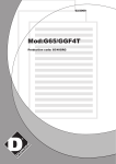
FIG. 1 shows the face of a test ?xture, and provides
prising service manual, template, and test ?xture. The
legendry which will explain to the user the features of
manual presents focused, step-by-step procedures for
locating and correcting malfunctions, and the template
the test ?xture in different or in somewhat different
terms than shown on the face of the test ?xture.
FIG. 2D shows the manual page which illustrates a
and test ?xture are coordinated with said procedures,
for providing functional checks, calibration, signal mea
surements, and so forth, with respect to various points
template according to the invention, and again suitable
legends expand upon what is evident from the face of
and components, either on the circuit board or else
where in the controller.
the template. For example, the legend “Main Ampli?er
Area (Red)” and other color-associated legends, and
50 the “COLOR CODE” at the lower left corner of the
BRIEF DESCRIPTION OF THE DRAWINGS
FIGS. 1, 2 and 3 reproduce, a little less than full
scale, three pages of a service manual, according to the
invention.
FIG. 4 shows the circuitry of a test ?xture, according 55
to the invention.
7
on the board are illustrated, they are shown in a uni
description of the service system, and statement of user
form, low-saturation color, like grey, which contrasts
with the more vivid hues used for the other graphic
advantages, for example:
“The Taylor Service Mate System provides equipment
and procedures for testing, troubleshooting, repair and
“Main Ampli?er Area” is red, as are diodes D3 et al,
and the other circuit elements depicted within that out
line. Preferably, if the printed-circuit interconnections
The service manual preferably begins with a general
“TAYLOR SERVICE MATE (TM)”
template reinforce the signi?cance of the fact that the
circuitry, insofar as shown, is actually depicted in a
particular color. Thus, the dashed line around the
60
elements: letters, numbers, circuit element outlines.
For the user’s convenience in adding ad hoc notes in
pen or ink, as well as for visibility and durability, the
template surface may be coated with a matte ?nish
calibration of Taylor 1300 Series Instruments. The Tay
plastic. However, graphic complexity is inadvisable,
lor Service Mate System consists of
65 and, according to invention we provide substantially
The text ?xture.
Templates for circuit board troubleshooting.
Service kit of tools and replacement components.
only such information on the template as will be neces
sary in carrying out the procedures set forth in the
service manual. The gray interconnections are an ex
3
4,262,248
4
except for lacking drawings, is formatted like the pages
ception to this exclusionary aspect of the template
graphics, for the reason that, in principle, it is also desir
able to know circuit commons and the general lay of the
illustrated herein.
land so to speak. However, an unobtrusive color can be
used for these purposes without interfering or confusing
procedure which isolates a circuit problem to a section
of the circuitry. Each section of circuitry has a separate
the intended service procedures.
troubleshooting procedure which isolates the defective
“The following function check is a symptom analysis
Another page (not shown) depicts the layout of the
component, e.g, diode, transistor, integrated circuit,
trays of a spare parts and tool kit which can be used to
switch or meter.”
“This procedure will indicate if controller is function- .
augment a service system accordingly. The contents of
the trays are preferably coordinated with the service
manual and test ?xture.
Still another page (not shown) is con?ned to informa
tion relating to template selection for a particular instru
ing correctly. Incorrect calibration will affect instru
ment operation. Always check instrument calibration
before replacing any component. After component re
placement, check controller calibration and operation.
Make sure controller is operating correctly before put
ting it back into service.
ment. Again, generous room is provided for adding ad
hoc information, should the user ?nd it desirable to do
so.
Additional pages (not shown) are provided describ
ing or attaching a template to the “manual control cir
(1) At controller: Set auto-manual switch at M (man
ual).
cuit board” of a process controller, as well as attaching
(2) At test ?xture: Set selector switch at OUTPUT. Set
the FIG. 2 template to the controller circuit board of 20
loop switch at OPEN. Set circuit common switch at
the process controller.
OFF.
FIG. 3 shows the service manual pages illustrating
(3) At controller: Depress and hold OUT button. At
same time, depress and hold both up button (V) and
the servicing set-up for DC-powered controllers. Also,
the DC scheme shows an AC line cord, as well as the
DC supply (which is actually itself a plug-in) because
25
the same actual test ?xture also provides for a quite
fast button (F) until output pointer (left pointer)
reaches top of meter scale (changes at about 15% per
second). Release both up and fast buttons. Then,
depress and hold down button (A) and fast button (F)
until output pointer reaches bottom of meter scale
(changes at about 15% per second). Output indicator
similar AC-powered controller servicing set-up.
A following page (not shown) orients the user to the
speci?c procedures of troubleshooting and focuses on a
particular instrument, namely, assignee’s Taylor Instru
(left pointer) should move to top of meter scale
(100%) and then to bottom of meter scale (0%).
ment Company Division 1312 Indicating Controllers
with Full View Scale, Models A and B. This controller
family is of the well-known PID type based on “opera
tional ampli?er” principles, for example, as set forth in
(4) At voltmeter: From 0.25 V dc (when output pointer
is at bottom of scale) to 1.25 V dc (when output
pointer is at top of scale).
If not, controller does not operate correctly when
our assignee’s US Pat. No. 3,127,109 to N. B. Nichols.
A suitable text is:
in manual control.
“TROUBLESHOOTING” with Controller Text
(5) At controller: Set auto-manual switch at A (auto).
Set remote-local switch at L(local).
(6) At test ?xture: Set loop switch at CLOSED.
(7) At controller: Vary set-point from 0 to 100%.
Fixture for Taylor 1312R Indicating Controllers with
Full View Scale Models A and B
NOTE
Set-point indicator (right pointer) Should follow
“The following troubleshooting procedures are for
set-point adjustment.
component failure in one section of the circuit. If com
ponents fail in more than one section of circuitry, a
Process pointer (left pointer) should follow set
point indication (right pointer).
,
Output indicator (left pointer) should move to top
combination of the following procedures will be re
quired. Most components that fail will be diodes, tran
sistors, integrated circuits, switches and meters.
of meter scale (100%) and then to bottom of
meter scale (0%).
If not, controller does not operate correctly when
in automatic control.
The circuit boards are coated with varnish. To re
move and replace components the varnish must be re
moved by scraping or burning it off with a soldering 50
(8) At voltmeter: From 0.25 V dc (when output pointer
iron. After the component has been replaced and any
is at bottom of scale) to 1.25 V do (when output
necessary testing or calibration is completed, the area
pointer is at top of scale).
where the varnish was removed should be cleaned and
If not, controller does not operate correctly when
revamished.”
in automatic control.
55
(9) At test ?xture: Set selector switch at SET-POINT
Following this are pages (not shown) which self
MONITOR.
explanatorily illustrate, verbally and pictorially, further
(10) At controller: Vary set-point from 0 to 100%.
preliminaries to beginning the troubleshooting, e.g.,
(11) At voltmeter: 0.25 to 1.25 V dc. If not, set-point
checking for broken wires, and burned or otherwise
physically damaged components, overheating when 60 monitor signal is incorrect.
(12) At test ?xture: Set selector switch at INPUT. Set
tumed-on, and putting the instrument into condition for
loop switch at OPEN. Set input/voltage source 1
service, as by jumpering the controller internal feed
switch at ON.
back circuit, and making response and other operational
settings which are appropriate for servicing.
These preliminaries continue with “Controller Func
tion Check”, a purely verbal procedure, quoted herein
below as running text, but, in the manual, more com
fortably spread over 9 service manual pages which,
Vary input/voltage source 1 potentiometer until
65
voltmeter indicates 0.75 V dc+0.00l.
(l 3) At test ?xture: Set selector switch at DEVIATION
MONITOR.
(14) At controller: Vary set-point from 0 to 100%.
5
4,262,248
(15) At voltmeter: Deviation monitor signal should be'
Approx. —0.5 V dc when set-point is at 0%. Approx.
0 V do when set-point is at 50%. Aprox. +0.5 V do
(Model A Controllers).
Refer to 14 Troubleshooting Manual Ampli?er Circuit
when set-point is at 100%. If not, deviation monitor
signal is incorrect.
(Model B Controllers).
5 Refer to 15 Troubleshooting Manual Buffer Ampli?er
Circuit.”
(16) At test ?xture: Set selector switch at EXTERNAL
FEEDBACK.
“When controller does not operate in either auto (Step
(17) At controller: Vary set-point from 0 to 100%.
(18) At voltmeter: Feedback signal should be Approx.
+10 V do when set-point is at 0%. Approx. 0 V do
7) or manual (Step 4):
Set-point monitor (Step 11), deviation monitor (Step 15)
and feedback signals (Step 18) are correct-Refer to
1 Troubleshooting Power Supply Circuit and 7 Trou
when set-point is at 50%. Approx. — 10 V do when
set-point is at 100%. If not, feedback signal is incor
bleshooting Voltage-to-Current Converter.
rect.
(19) At controller: If controller does not have remote
local switch, go to Step 22. If controller has remote
local switch, set remote-local switch at R (remote).
(20) At test ?xture: Set selector switch at DEVIATION
MONITOR. Set remote set-point/voltage source 2
switch at ON. Set remote set-point/voltage source 2
6
Refer to 13 Troubleshooting Manual Amplifier Circuit
Incorrect feedback signal (Step 18)~—Refer to l Trou
bleshooting Power Supply Circuit, 5 Troubleshoot
ing Main Ampli?er Circuit and 6 Troubleshooting
Diode Limiter Circuit.”
The foregoing function checking is diagnostic in
20
nature and leads to the following speci?c procedures:
indicator is at 50%. Approx. +0.5 V do when set
25
point indicator is at 100%.
If not, controller does not operate correctly from
(1) Troubleshooting Power Supply Circuit
(2) Troubleshooting Set~Point Adjustment
(3) Troubleshooting Remote-Local Switch
(4) Troubleshooting Deviation Ampli?er Circuit
(5) Troubleshooting Main Ampli?er Circuit
(6) Troubleshooting Diode Limiter Circuit
(7) Troubleshooting Voltage-To-Current Converter
(8) Troubleshooting Set-Point Meter Circuit
(9) Troubleshooting Process-Output Meter Circuit
(10) Troubleshooting Set-Point Buffer Ampli?er Cir
potentiometer to get 0, 50 and 100% of set-point
indicator (right pointer).
(21) At voltmeter: Approx. -0.5 V do when set-point
indicator is at 0%. Approx. 0 V do when set-point
remote set-point signal.
(22) At test ?xture: Set selector switch at XMTR SUP.
Set remote set-point switch at OFF. Set input/volt
age source 1 switch at OFF.
cuit
(23) At voltmeter: Between 24.25 and 25.75 V do
(11) Troubleshooting Manual Control Switch Circuit
It‘ not, transmitter power supply is defective.”
“When controller operates in both auto (Step 7) and
manual (Step 4) except for the following:
35
No output indication (Steps 4 and 8)—Refer to 9 Trou
bleshooting Process-Output Meter Circuit.
No Process indication (Step 7)—Refer to 9 Trouble
shooting Process-Output Meter Circuit.
Inasmuch as the service manual pages for these proce
dures will be formatted in accordance with the pages
No Set~Point indication (Step 7)—Refer to 8 Trouble
shooting Set-Point Meter Circuit.
No Set-Point monitor signal (Step 1l)—Refer to 10
Troubleshooting Set-Point Buffer Ampli?er Circuit.
Will not operate from remote set-point signal (Step
2l)—Refer to 3 Troubleshooting Remote-Local
Switch.
No transmitter power supply voltage (Step 23)—Refer
to 16 Troubleshooting Transmitter Power Supply.”
previously described, showing the troubleshooting pro
cedure pages or describing their content is unnecessary,
especially since we do not regard the details of proce
45 dures themselves as part of the invention we seek to
patent here.
The service manual also includes pages describing the
various calibration procedures, detailed circuit compo
nent location diagrams, and parts lists, and as in the case
of troubleshooting procedures, and for the same rea
“When controller operates in manual (Step 4) but not in
auto (Step 7):
Incorrect deviation monitor signal (Step l5)—Refer to
4 Troubleshooting Deviation Ampli?er Circuit.
Incorrect set-point monitor signal (Step l1)—Refer to 2
sons, we do not show service manual pages devoted to
the calibration procedures. These Figures are individu
ally self-explanatory, etc.
Referring now to FIGS. 3 and 4, the function switch
55
Troubleshooting Set-Point Adjustment.”
When controller does not operate in either auto (Step 7)
or manual (Step 4):
Refer to 2 Troubleshooting Set-Point Adjustment.”
“When controller operates in auto but not in manual:
Refer to 11 Troubleshooting Manual Control Switch
Circuit
Refer to 12 Troubleshooting Relay K101
101 of the former is represented in the latter by nine
labeled double-pole, single throw switches, which pref
erably are actually provided in the form of the usual
“When controller operates in manual (Step 4) and in
auto with the remote set-point signal (Step 21), but not
with the local set-point (Step 11):
(12) Troubleshooting Relay K101
(13) Troubleshooting Manual Ampli?er Circuit (Model
A Controllers)
(14) Troubleshooting Manual Ampli?er Circuit (Model
B Controllers)
(15) Troubleshooting Manual Buffer Ampli?er Circuit
(16) Troubleshooting Transmitter Power Supply
rotary switched having ganged contact wafers (not
shown).
For the most part, switch 101 selectively connects
60
jacks 102 and pin contacts 103, comprising pairs
wherein; the second of each pair is either at circuit
common or negative potential, and wherein the jack
voltage will represent, respectively, the controller’s
65 external feedback voltage, the deviation of the process
variable from the set point value desired for it, the con
troller’s output and input voltages, the value of a remote
set point, transmitter output voltage and the active set
1
4
t
l
|
7
4,262,248
8
servicing information by a human operator, will
inform said operator whether or not said instru
point of the control (to which the remote set point
would normally an alternative).
The voltages at jacks 102 can be traced back ulti
mately to one or another of sources 104, 105, 106 and
107, respectively an AC line cord, a 24 V DC power 5
ment be in need or service, and what sort of ser
vice, if any be needed;
said ?rst connecting means including switch means
and potentiometer means and interconnecting an
supply, and ?rst and second 1.5 volt batteries (not
shown, but normally mounted in the case 100 of test
input voltage to the input of said instrument for
causing said circuit means to produce an open loop
?xture). Selection of sources 104 and 105 is by means of
a single-pole, double throw switch 106A having an
intermediate off-position wherein both sources are dis
connected. In a manner of speaking, selection is also
controlled by service manual directions for line-cord
output voltage in response to said input voltage;
said potentiometer means being operable to set the i
value of said input voltage, and said switch means
being operable to simultaneously disconnect said
input voltage from said input and close a loop
plug-in.
around said circuit;
said second connecting means providing for selec
’ tively connecting said input voltage and said
output voltage to said test instrumentation, both
when said loop is closed and when said loop is
open.
Double pole, single throw switches 109 and 108, and
potentiometers 109A and 110, respectively, provide
adjustable input voltage across onepair of pins 103 and
remote set point voltage across another pair thereof.
Double pole, single throw switch 111 provides for alter
native open-loop a'nd closed-loop testing.
Cables 112 and 113 provide for connecting power 20
and test signals between the controller 114 and the test
?xture 100. In the former case, these signals are applied
2. A system for testing and servicing a circuit means
of an instrument for receiving, producing and/or han
dling a plurality of signals representative of process
measurement and/or control, wherein said circuit
via plug-in connection 115 to the regular instrument
means is involved in receiving, producing or handling
terminals via which process information and control
signals pass between controller and the process it is 25 at least a portion of said plurality of signals, said system
comprising, in combination, a book, a template, and a
controlling and via which the controller is energized in
order to power its controlling and signal handling capa
test ?xture;
said book having information therein for testing and
bilities.
servicing said instrument;
said template having portrayals of portions of said
circuit graphically depicted thereon, said template
Cables 112 and 113 connect to the test ?xture cir
cuitry via connectors 116 and 117 of any suitable form.
Into jacks 102 are removably plugged leads 118 of
test probes 119. Other leads 120 are removably plugged
into jacks 121 of the test ?xture for connecting test
?xture circuitry to the input terminals 122 of a voltme
ter 123.
having means for removably mounting said tem
plate on said circuit means, and said template, .
when so mounted, having access means for provid
35
In FIG. 3, references numerals 126 through the 131
respectively identify the operating hardware (e.g., tog
gles) of switches 106, 107 and 108, operating hardward
(e.g., rotatable knobs) of potentiometers 109A and 110,
and the operating hardward of switch 111. In addition,
respective pilot lights 132 and 133 are provided for
indicating whether any, and which, power is on pins of
the instrument connection 115.
Finally, the test ?xture provides a jack 134 and a jack
135 into either of which a jumper wire can be plugged.
By connecting jack 134 or 135 to the appropriate test
point of the circuit, via the jumper wire, and properly
setting test ?xture switches, sections of the circuit being
serviced can be calibrated.
Having described our invention as required by 35 50
USC 112, we claim:
1. A system for testing and servicing a circuit means
ing probe access, by probe means, to test points of
said circuit means;
said test ?xture having ?rst connecting means for
connecting test signals to said instrument such as to
cause diagnostic signals to appear at at least certain
of said test points, said test ?xture have second
connecting means for connecting said diagnostic
signals to test instrumentation to produce informa
tion which, when compared with said testing and
servicing information by a human operator, will
inform said operator whether or not said instru
ment be in need of service, and what sort of ser
vice, if any, be needed,
said ?rst connecting means including switch means
‘and potentiometer means and interconnecting an
input voltage to the input of said instrument for ‘
causing said circuit means to produce an open loop
output voltage in response to said input voltage;
dling a plurality of signals representative of process
said potentiometer means being operable to set the
value of said input voltage, and swid switch means
measurement and/or control, wherein said instrument
has test points, said circuit means is involved in receiv
ing, producing or handling at least a portion of said
being operable to simultaneously disconnect said
input voltage from said input and close a loop
around said circuit;
plurality of signals, said system being of the type com
prising means having information for testing and servic
ing said instrument, including applying probe means to 60
said second connecting means providing for selec
of an instrument for receiving, producing and/or han
said test points, and a test ?xture;
tively connecting said input voltage and said
output voltage to said test instrumentation, both
when said loop is closed and when said loop is
open.
said test ?xture having ?rst connecting means for
3. A test ?xture in a system for testing and servicing
connecting test signals to said instrument such as to
an instrument for receiving, producing and/or handling
cause diagnostic signals to appear at at least certain
of said test points, said test ?xture have second 65 a plurality of signals representative of process measure
ment and/or control, wherein said instrument has test
connecting means for connecting said diagnostic
points, said system being of the type comprising means
signals to test instrumentation to produce informa
having information for testing and servicing said instru
tion which, when compared with said testing and
9
4,262,248
10
ment, including applying probe means to said test
Points;
said test ?xture having ?rst connecting means for
input voltage to the input of said instrument for
causing said instrument to produce an open loop
connecting test signals to an instrument such as to
said potentiometer means being operable to set the
output voltage in response to said input voltage;
guise q‘agmfl‘ésignfs to alipeaiiatt a: ‘Fast cegam 5
.35 pom o Sal “is mmen ’ Sm
es “mire 3?"
mg second connecting means for connecting said
value of said input voltage, and said switch means
being operable to simultaneously disconnect said
in ut Volta e from said in at and close a loo
diagnostic signals to test instrumentation to pro-
p
duce information which, when compared with
predetermined testing and servicing information by 10
d
.5. t
t_
p
p
at?“ 83‘ ms mm?“ ’
_ _
f
5a“? second cmmfactmg Fla?!“ Provldmg or sale?‘
a human operator, will inform said operator
twely connectmg sfud mifut Voltage find sa‘d
whether or not said instrument be in need of Set.
vice, and what sort of sci-vie, if any, be need;
said ?rst connecting means including switch means
output voltage to said test lnstrumentation, both
when said loop is closed and when said loop 18
open.
and potentiometer means and interconnecting an 15
20
25
30
35
40
45
50
55
6O
65
*
*
*
*
*