1
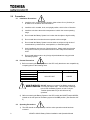
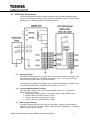
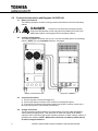
BATTERY CABINET
1600XP SERIES
8-22kVA BATTERY CABINET
INSTALLATION AND OPERATION MANUAL
SINGLE PHASE – 8/10/14/18/22 kVA: 288Vdc
Part# 64024-001
March 2012
1600XP Series Battery Cabinet Installation and Operation Manual
1600XP SERIES
8-22kVA BATTERY CABINET
INSTALLATION AND OPERATION MANUAL
SINGLE PHASE- 8/10/14/18/22 kVA: 288 Vdc
Part# 64024-001
March 2012
1600XP Series Battery Cabinet Installation and Operation Manual
IMPORTANT NOTICE
The instructions contained in this manual are not intended to cover all of the details
or variations in equipment, or to provide for every possible contingency to be met in
connection with installation, operation, or maintenance. Should further information be
desired or particular problems arise which are not covered sufficiently for the
purchaser's purposes, the matter should be referred to the local Toshiba sales office.
The contents of this instruction manual shall not become a part of or modify any
prior or existing agreement, commitment, or relationship. The sales contract contains
the entire obligation of Toshiba International Corporation's UPS Division. The warranty
contained in the contract between the parties is the sole warranty of Toshiba
International Corporation's UPS Division and any statements contained herein do not
create new warranties or modify the existing warranty.
Any electrical or mechanical modifications to this equipment, without prior
written consent of Toshiba International Corporation, will void all warranties and
may void UL/CUL listing. Unauthorized modifications also can result in personal
injury, death, or destruction of the equipment.
UNINTERRUPTIBLE POWER SYSTEM BATTERY CABINET SYSTEM
If additional information or technical assistance is required call Toshiba’s Customer Support
Center toll free at 1-877-867-8773 or write to: Toshiba International Corporation, 13131 W. Little
York Rd., Houston, TX 77041-9990.
Please complete the following information for your records and keep this manual with the
equipment:
Model Number:
Serial Number:
Date of Installation:
Inspected By:
1600XP Series Battery Cabinet Installation and Operation Manual
Table of Contents
GENERAL SAFETY INSTRUCTIONS .................................................................................................................... 1
IMPORTANT SAFETY INSTRUCTIONS ............................................................................................................... 2
IMPORTANT BATTERY SAFETY INSTRUCTIONS ................................................................................................ 3
1.0
1.1
1.2
1.3
2.0
2.1
2.2
2.3
3.0
3.1
3.2
3.3
4.0
4.1
4.2
4.3
4.4
5.0
5.1
5.2
5.3
5.4
6.0
6.1
6.2
6.3
7.0
7.1
7.2
8.0
8.1
8.2
8.3
9.0
INSPECTION / STORAGE / DISPOSAL .................................................................................................... 5
INSPECTION OF THE NEW BATTERY SYSTEM...................................................................................................... 5
STORAGE OF BATTERY EQUIPMENT ................................................................................................................ 5
DISPOSAL .................................................................................................................................................. 5
PRECAUTIONS ..................................................................................................................................... 6
INSTALLATION PRECAUTIONS......................................................................................................................... 6
PRESTART PRECAUTIONS .............................................................................................................................. 6
OPERATING PRECAUTIONS ............................................................................................................................ 6
UPS POWER CONNECTIONS ................................................................................................................. 7
UPS INPUT VOLTAGE .................................................................................................................................. 7
CONNECTING MULTIPLE BATTERY CABINETS .................................................................................................... 7
BATTERY CABINET CABLING .......................................................................................................................... 7
CONNECTION INSTRUCTIONS AND DIAGRAMS 14/18/22 KVA............................................................. 8
BATTERY CONNECTIONS ............................................................................................................................... 8
14/18/22 KVA ILLUSTRATION...................................................................................................................... 8
CONNECTION PROCEDURE ............................................................................................................................ 8
CHARGER CONNECTION ............................................................................................................................... 8
CONNECTION INSTRUCTIONS AND DIAGRAMS 8/10 KVA .................................................................... 9
BATTERY CONNECTIONS ............................................................................................................................... 9
8/10 KVA ILLUSTRATION ............................................................................................................................. 9
CONNECTION PROCEDURE ............................................................................................................................ 9
CHARGER CONNECTION ............................................................................................................................... 9
PREVENTIVE AND SCHEDULED MAINTENANCE / PART REPLACEMENT .............................................. 10
PREVENTIVE MAINTENANCE........................................................................................................................ 10
PARTS REPLACEMENT ................................................................................................................................ 10
POWER CABLES ........................................................................................................................................ 11
EMERGENCY POWER OFF (EPO) ......................................................................................................... 11
EPO CABLING .......................................................................................................................................... 11
EPO OPERATION ...................................................................................................................................... 11
EXTERNAL LAYOUTS / DIMENSIONS / SHIPPING WEIGHTS ................................................................ 12
EXTERNAL LAYOUTS................................................................................................................................... 12
DIMENSIONS............................................................................................................................................ 12
SHIPPING WEIGHTS ................................................................................................................................... 12
1600XP SYSTEM BACKUP RUNTIME ................................................................................................... 13
1600XP 8-22kVA Battery Cabinet Installation and Operation Manual
i
ii
1600XP 8-22kVA Battery Cabinet Installation and Operation Manual
GENERAL SAFETY INSTRUCTIONS
Warnings in this manual appear in any of four ways:
1)
Danger- The danger symbol is a lightning bolt mark enclosed in a triangle which precedes the
3/16-inch high letters spelling the word “DANGER”. The danger symbol is used to indicate
imminently hazardous situations, locations, and conditions which, if not avoided, WILL result
in death, serious injury, and/or severe property damage.
DANGER
2)
Warning- The warning symbol is an exclamation mark in a triangle which precedes the 3/16inch high letters spelling the word “WARNING”. The warning symbol is used to indicate
potentially hazardous situations and conditions which, if not avoided COULD result in serious
injury or death. Severe property damage COULD also occur.
WARNING
3)
Caution- The caution symbol is an exclamation mark enclosed in a triangle which precedes
the 3/16-inch high letters spelling the word “CAUTION”. The caution symbol is used to
indicate potentially hazardous situations and conditions which, if not avoided may result in
injury. Equipment damage may also occur.
CAUTION
4)
Attention warnings- The attention warning symbol is an exclamation mark enclosed in a
triangle which precedes the 3/16-inch high letters spelling the word “ATTENTION”. The
Attention warning symbol is used to indicate situations and conditions that can cause
operator injury and/or equipment damage.
ATTENTION
Other warning symbols may appear along with the Danger and Caution symbol and are used to specify
special hazards. These warnings describe particular areas where special care and/or procedures are
required in order to prevent serious injury and possible death:
1)
Electrical warnings- The electrical warning symbol is a lighting bolt mark enclosed in a
triangle. The Electrical warning symbol is used to indicate high voltage locations and
conditions that may cause serious injury or death if the proper precautions are not observed:
2)
Explosion warnings- The explosion warning symbol is an explosion mark enclosed in a
triangle. The Explosion warning symbol is used to indicate locations and conditions where
molten, exploding parts may cause serious injury or death if the proper precautions are not
observed:
1600XP 8-22kVA Battery Cabinet Installation and Operation Manual
1
IMPORTANT SAFETY INSTRUCTIONS
SAVE THESE INSTRUCTIONS
This manual contains important instructions that should be followed during installation and maintenance
of the Battery System model UH31-BC-1825.
The maximum ambient temperature in which a Battery System should be operated is 104 °F (40 °C).
The nominal battery voltage for the battery cabinet is as follows:
Model
Voltage
UH31-BC-1825
288 VDC
Battery Pack Information:
Battery Packs
Battery Pack Size
HxWxD (max)
Battery Pack Quantity
Battery Manufacturer
Battery Type
Toshiba Part Number for
Battery Pack
Designed for battery acid leakage containment with (6) batteries per pack.
5 in. (127 mm) x 7.3 in. (185 mm) x 18.2 in. (462 mm)
12
Yuasa
REW-45
51896
Misuse of this equipment could result in human injury and equipment
damage. In no event will Toshiba Corporation be responsible or liable for
either indirect or consequential damage or injury that may result from the misuse of this
equipment.
CAUTION
CAUTION
Do not dispose of the batteries in a fire. The batteries may explode.
CAUTION
Do not open or mutilate the batteries. Released electrolyte is harmful to
the eyes and skin and could also be toxic.
unit contains sealed lead acid batteries. Lack of preventative
WARNING This
maintenance could result in batteries exploding and emitting gasses
and/or flame. An authorized, trained technician must perform annual preventative maintenance.
to replace a battery before it becomes exhausted may cause the
WARNING Failure
case to crack, possibly releasing electrolytes from inside the battery, and
resulting in secondary faults such as odor, smoke, and fire.
and servicing of batteries should be performed by personnel
WARNING Installation
knowledgeable of batteries and the required precautions. Keep
unauthorized personnel away from the batteries.
2
1600XP 8-22kVA Battery Cabinet Installation and Operation Manual
IMPORTANT BATTERY SAFETY INSTRUCTIONS
maintenance to the battery system of this unit must be done by a
WARNING Proper
qualified service technician. This is essential to the safety and reliability
of your UPS system. Refer to service manual.
A battery can present a risk of electrical shock and high short
circuit current. The following precautions should be observed
when working with batteries.
Verify that the UPS is off and that the power cord is disconnected from the power source.
Remove watches, rings or other metal objects.
Use tools with insulated handles to prevent inadvertent shorts.
Wear rubber gloves and boots.
Do not lay tools or metal parts on top of batteries.
Determine if the battery is inadvertently grounded. If inadvertently grounded, remove
source of ground. Contact with any part of a grounded battery can result in
electrical shock. The likelihood of such shock will be reduced if such grounds are
removed during installation and maintenance.
Verify circuit polarities prior to making connections.
Disconnect charging source and load prior to connecting or disconnecting terminals.
DANGER
1)
2)
3)
4)
5)
6)
7)
8)
9)
10
11
12
VRLA batteries may emit highly flammable hydrogen gas. During charging and operation. Do not
or spark in the immediate area of the batteries. This includes static electricity from the body.
Do not attempt to open the batteries in order to add water or sample the specific gravity of the
electrolyte. The batteries are valve regulated lead acid type and such servicing is not possible
without damaging the battery.
Use proper lifting means when moving batteries and wear all appropriate safety clothing and
equipment.
Do not dispose of lead acid batteries except through channels in accordance with local, state
and federal regulations.
1600XP 8-22kVA Battery Cabinet Installation and Operation Manual
3
INSTRUCTIONS IMPORTANTES CONCERNANT
LA SÉCURITÉ
Cette notice contient des
instructions importantes
concernant la sécurté
Un battery puet présenter un risque de choc électrique, de brûlure
par transfert d’ énergie.
CONSERVER CES INSTRUCTIONS
ATTENTION
ATTENTION
Model Capacity
UH31-BC-1825
Manufacturer
YUASA
ATTENTION
4
Por le replacement, utiliser le même nombre de batteries du modéle
suivant.
Type
REW-45
Quantity
72
L’élimination des batteries est règlementèe. Consultar les codes
locaux à cet effet.
1600XP 8-22kVA Battery Cabinet Installation and Operation Manual
1.0
Inspection / Storage / Disposal
1.1
Inspection of the New Battery System
Upon receipt of the Battery System, a careful inspection for shipping damage should be
made.
1) Check the unit for loose, broken, bent or otherwise damaged parts. If damage has
occurred during shipment, keep all original crating and packing materials for return to
the shipping agent. The equipment warranty will not apply to units which are
damaged during shipment.
2) Check to see that the rated capacity and the model number specified on the
nameplate conform to the order specifications.
1.2
Storage of Battery Equipment
If the Battery System is to be subjected to long or short term storage, the following
guidelines should be used.
Avoid:
1) Storage in sites subject to extreme changes in temperature or high humidity.
2) Storage in sites subject to exposure of high levels of dust or metal particles.
3) Storage on inclined floor surfaces or in sites subject to excessive vibration.
Before storing:
1) Charge the system's batteries.
2) Place the Battery System’s input switch (MCCB-C) in the OFF position.
Storing:
1) Store within a temperature range of -4 to 104 °F (-20 to 40 °C).
2) For best results, store the Battery System in the original shipping container and place
on a wood or metal pallet.
3) The optimum storage temperature is 70 °F (21 °C). Higher ambient temperatures
cause UPS batteries to need recharging more frequently.
4) If stored in an ambient temperature under 68 °F (20 °C); recharge the batteries every
9 months.
5) If stored in an ambient temperature of 68 to 86 °F (20 to 30 °C); recharge the
batteries every 6 months.
6) If stored in an ambient temperature of 86 to 104 °F (30 to 40 °C); recharge the
batteries every 3 months.
1.3
Disposal
Please contact your state environmental agency for details on disposal of electrical
components and packaging in your particular area.
It is illegal to dump lead-acid batteries in landfills or dispose of improperly. Please
help our Earth by contacting the environmental protection agencies in your area, the
battery manufacturer, or call Toshiba toll-free at (877) 867-8773 for more information about
recycling.
1600XP 8-22kVA Battery Cabinet Installation and Operation Manual
5
2.0
Precautions
2.1
2.2
Installation Precautions
1)
Install the unit in a well ventilated location; allow at least 10 cm (4 inches) on
all sides for air ventilation and maintenance.
2)
Install the unit in a stable, level, and upright position, which is free of vibration.
3)
Install the unit where the ambient temperature is within the correct operating
range.
4)
Do not install the Battery System in a location that is subject to high humidity.
5)
Do not install the unit at sites that are exposed to direct sunlight.
6)
Do not install the Battery System in areas which are subject to high levels of
contamination by airborne dust, metal particles, or flammable gases.
7)
Avoid installation near sources of electrical noise. Always make sure that the
unit ground is intact to prevent electrical shock and to help reduce electrical
noise.
8)
Do not install where water or any foreign objects/substances may get inside
the Battery System.
Prestart Precautions
1) Before connecting the Battery System to the UPS verify that the two are compatible by
comparing them to the following chart.
UPS Model Number
UH3G2L080C61T
UH3G2L100C61T
UH3G2L140C61T
UH3G2L180C61T
UH3G2L220C61T
Battery Cabinet Model Number
Battery Voltage
UH31-BC-1825
288VDC
NOT attempt to connect if the Model numbers do
WARNING DO
not match the above chart. This will result in damage
to the UPS, the Battery System, or both. Call your
Toshiba representative if you should have any
questions.
2) Before connecting the Battery System to the UPS; switch the ON/OFF switch MCCB2,
located on the rear panel of the battery system to the OFF position. (See Sections 4 &
5)
2.3
Operating Precautions
1) The UPS should not be powered up until the entire operation manual has been
reviewed.
6
1600XP 8-22kVA Battery Cabinet Installation and Operation Manual
3.0
UPS Power Connections
The following illustration shows the wiring connections from the power distribution panel
(not part of the UPS) to the UPS, and from the UPS to the battery cabinet. This connection
diagram is to be used with the UH31-BC-1825 Battery Unit.
3.1
UPS Input Voltage
If the UPS AC input power is 208 V rated, connect a jumper wire between terminals 11 and
12 on the UPS terminal block. DO NOT jumper terminal 13 to 11 or 12. The UPS ships
from the factory with the jumper in the 208 V position.
If the UPS AC input power is 240 V rated, connect a jumper wire between terminals 12 and
13 on the UPS terminal block. DO NOT jumper terminal 11 to 12 or 13.
3.2
Connecting Multiple Battery Cabinets
Up to two battery cabinets may be connected in parallel to the UPS. To connect two
battery cabinets to the UPS,
1. Connect the first battery cabinet to the UPS as shown in the illustration above.
2. Connect cabinet 2 CN12A to cabinet 1 CN22,
3. Connect cabinet 2 CN13A to cabinet 1 CN23,
4. Connect cabinet 2 CN14A to cabinet 1 CN24.
3.3
Battery Cabinet Cabling
The battery cabinets ship with a set of six-foot long cables. Contact Toshiba Customer
Support at 1-877-867-8773 if longer cables are required for your application, or if additional
cables or connectors are required.
1600XP 8-22kVA Battery Cabinet Installation and Operation Manual
7
4.0
Connection Instructions and Diagrams 14/18/22 kVA
4.1
Battery Connections
The following illustration shows the wiring connections between the UPS and the battery
cabinet.
DANGER
Contacts are not rated with interrupting capacity.
Ensure the MCCB switch on the rear panel of the Battery Unit is set to the
OFF position before connecting the UPS to the battery cabinet.
4.2
14/18/22 kVA Illustration
The following diagram shows the rear view of a 14/18/22 kVA UPS and an 18 kVA battery
cabinet. NOTE: Use only compatible cabinets! See page 6.
1600XP 14/18/22 kVA UPS
8
BATTERY CABINET
4.3
Connection Procedure
1) Ensure all power is locked and tagged out.
2) Remove the battery connector cover mounted on the UPS back panel.
3) Plug the DC Connectors of the battery cabinet into the DC Connector socket on the
UPS unit (see section 3.0 UPS Power Connections).
4.4
Charger Connection
The UPS internal multi-tap transformer provides 240Vac to the UH31-BC-1825 Battery
Cabinet battery charging circuit. This connection is made from CN14A of the battery
cabinet to CN14 of the UPS (and CN14A of battery cabinet 2 to CN24 of battery cabinet 1 if
paralleling two cabinets). NOTE: Without this connection, the battery cabinet will not
be able to charge its batteries.
1600XP 8-22kVA Battery Cabinet Installation and Operation Manual
5.0
Connection Instructions and Diagrams 8/10 kVA
5.1
Battery Connections
The following illustration shows the wiring connections between the UPS and the Battery
Unit.
DANGER
Contacts are not rated with interrupting capacity.
Ensure the MCCB switch on the rear panel of the Battery Unit is set to the
OFF position before connecting the UPS to the battery cabinet.
5.2
8/10 kVA Illustration
The following diagram shows the rear view of an 8/10 kVA UPS and a battery cabinet.
NOTE: Use only compatible cabinets! See page 6.
1600XP 8/10 kVA UPS
5.3
5.4
BATTERY CABINET
Connection Procedure
1) Ensure all power is locked and tagged out.
2) Remove the battery connector cover mounted on the UPS back panel.
3) Plug the DC Connectors of the Battery unit into the DC Connector socket on the
UPS unit (see section 3.0 UPS Power Connections).
Charger Connection
Battery cabinet model UH31-BC-1825 requires a 240 Vac connection between the UPS
and battery cabinet for battery charging. This connection is made from CN14A of the
battery cabinet to CN14 of the UPS (and CN14A of battery cabinet 2 to CN24 of battery
cabinet 1 if paralleling cabinets). NOTE: Without this connection the battery cabinet
will not be able to charge its batteries.
1600XP 8-22kVA Battery Cabinet Installation and Operation Manual
9
6.0
Preventive and Scheduled Maintenance / Part Replacement
6.1
Preventive Maintenance
Toshiba's 1600XP Series of UPS battery cabinets have been designed to provide years of
trouble-free operation requiring a minimum of preventive maintenance.
The best preventive measure that the battery cabinet user can take is to keep the area
around the unit, particularly the air inlet vents, clean and free of moisture and dust
accumulations. If the atmosphere of the installation site is very dusty, use a vacuum
cleaner to periodically remove dust accumulations from the air inlet vents. Schedule
authorized service centers to perform internal parts inspections annually.
CAUTION
Before performing any maintenance, the technician should become
familiar with and follow the important safety instructions on pages 1–4.
WARNING
Proper maintenance of the battery system of this unit by factory authorized
personnel is essential to the safety and reliability of your battery cabinet
system. Refer to service manual.
6.2
Parts Replacement
The following list shows intervals for periodic maintenance and replacement of certain UPS
parts.
Batteries: VRLA batteries are maintenance free with respect to electrolyte only.
The charging voltage, temperature, performance and connection resistance must
be checked periodically. Necessary corrective actions must be made in order to
assure safe reliable power is supplied by the battery cabinet. Charging voltage,
storage/operating temperature, charging cycles, and connection resistance all
affect battery life.
The recommended battery replacement interval is 3 to 5 years. All of the
batteries must be replaced at the same time.
Monthly Maintenance
A. Visual Checks:
1. Leakage
2. Corrosion on positive terminal
B. Check battery temperature at the negative terminal.
C. Measure and record the system float charging voltage.
D. Measure and record the individual unit’s battery tray voltage.
Semi-Annual maintenance
A. Repeat the monthly checks.
B. Perform a 10-second high rate (e.g. 100 amp) load test on the individual
batteries.
C. Re-torque all inter-battery connecting hardware (if applicable).
D. Perform inter-battery connector resistance checks.
Component*
Function
FU1, FU2
Control Power Fuses
Battery Tray Fuse
Internal Battery tray Fuse
Battery Pack
Replaceable Battery Pack
* Field Service replaceable parts only.
10
Rating
500 V, 10 A
500 V, 40 A
-
Part No.
00649
00637
51896
1600XP 8-22kVA Battery Cabinet Installation and Operation Manual
6.3
7.0
Power Cables
The three battery cabinet connector cables (battery positive, battery negative, and battery
charger) are each equipped with individually keyed Anderson connectors to prevent cross
connecting the battery cabinet and UPS circuitry.
Emergency Power Off (EPO)
7.1
EPO Cabling
The Battery Cabinet does not have an EPO. The EPO on the UPS connects to the battery
cabinet through the battery cabinet connection cable between CN14 and CN14A. No
other battery cabinet connection is needed.
7.2
EPO Operation
Pressing the EPO will cause the breaker on the battery cabinet and the UPS, to switch to
the OFF position simultaneously, disabling both the battery cabinet and the UPS.
The DC breaker on the battery cabinet is provided with a shunt trip. This device is
operated with an applied voltage of 120 Vac (supplied from the UPS). When the EPO is
pressed the UPS applies 120V to the shunt trip, causing the breaker to switch to the OFF
position.
1600XP 8-22kVA Battery Cabinet Installation and Operation Manual
11
8.0
External Layouts / Dimensions / Shipping Weights
8.1
External Layouts
8.2
Dimensions
Model
H
39.1 in.
(992 mm)
UH31-BC-1825
8.3
D
34.6 in.
(880 mm)
Shipping Weights
Model
UH31-BC-1825
12
W
17.5 in.
(445 mm)
Pounds
780 lbs.
Kilograms
354 kg
1600XP 8-22kVA Battery Cabinet Installation and Operation Manual
9.0
1600XP System Backup Runtime
The following runtime table gives the approximate combined backup runtimes at different
load levels for 1600XP UPS models equipped with one and two battery cabinets.
NOTE: These values are approximate and are dependent on many variables
including operating environment, age of the batteries, battery temperature, and
discharge history.
The load levels are given as a percent of rated load with a 0.7 and 0.85 power factor.
Table 1: Estimated Runtime of UPS with Battery Cabinet at Various Loads
UPS plus Two
Battery Cabinets
UPS plus One
Battery Cabinet
Rated Load
(0.7 PF)
UPS plus One
Battery Cabinet
30%
20%
10%
1600XP 8 kVA
50
55
65
70
85
95
120
150
180
>300*
1600XP 10 kVA
40
45
50
60
70
80
95
120
180
>300*
1600XP 14 kVA
35
40
45
55
60
80
90
120
165
>300*
1600XP 18 kVA
25
30
35
40
50
60
70
95
135
>300*
1600XP 22 kVA
20
24
28
35
40
50
60
80
110
240
1600XP 8 kVA
90
95
105
120
135
165
180
>300*
>300*
>300*
1600XP 10 kVA
70
80
90
95
110
135
165
240
>300*
>300*
1600XP 14 kVA
60
65
75
85
95
110
135
180
>300*
>300*
1600XP 18 kVA
45
50
60
70
75
90
110
150
180
>300*
1600XP 22 kVA
40
45
50
55
65
75
90
120
165
>300*
30%
20%
10%
Rated Load
(0.85 PF)
UPS plus Two
Battery Cabinets
100% 90% 80% 70% 60% 50% 40%
100% 90% 80% 70% 60% 50% 40%
1600XP 8 kVA
44
48
53
60
70
82
105
120
180
>300*
1600XP 10 kVA
35
40
44
50
57
70
82
105
150
>300*
1600XP 14 kVA
30
35
40
45
53
63
78
98
150
>300*
1600XP 18 kVA
21
24
28
35
42
50
60
82
112
240
1600XP 22 kVA
16
18
21
26
32
42
51
65
98
165
1600XP 8 kVA
72
82
90
105
120
135
165
240
>300*
>300*
1600XP 10 kVA
60
65
72
86
98
112
135
180
>300*
>300*
1600XP 14 kVA
51
55
63
72
82
98
120
150
240
>300*
1600XP 18 kVA
40
45
50
55
65
78
90
120
165
>300*
1600XP 22 kVA
30
36
42
46
53
63
82
105
150
>300*
* Estimated Runtime Exceeds 300 minutes.
1600XP 8-22kVA Battery Cabinet Installation and Operation Manual
13
14
1600XP 8-22kVA Battery Cabinet Installation and Operation Manual
INDUSTRIAL DIVISION
13131 West Little York Rd., Houston, TX 77041
Tel: 713/466-0277 Fax 713/466-8773
US 877/867-8773 Canada 800/872-2192 Mexico 01/800/527-1204
www.toshiba.com/ind
Printed in the U.S.A.