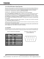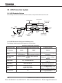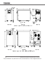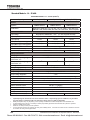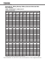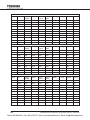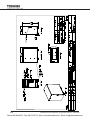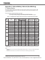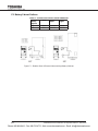
1
UNINTERRUPTIBLE POWER SYSTEM (UPS)
1600XP/1600XPi SERIES
INSTALLATION AND OPERATION MANUAL
SINGLE PHASE - 3.6/6/8/10/14/18/22 KVA
1600XPi
1600XP
Part # 60616-0010
October 2014
Manufactured in the USA
© Copyright 2014 TOSHIBA International Corporation
All rights reserved.
Phone: 800.894.0412 - Fax: 888.723.4773 - Web: www.ctiautomation.net - Email: [email protected]
b
1600XP/XPi Series Installation and Operation Manual – 60616-010
Phone: 800.894.0412 - Fax: 888.723.4773 - Web: www.ctiautomation.net - Email: [email protected]
Product Use and Warranty Restrictions
The Toshiba products listed in this document are intended for usage in general electronics applications
(computer, personal equipment, office equipment, measuring equipment, industrial robotics, domestic
appliances, etc.). These Toshiba products are neither intended nor warranted for usage in equipment that
requires extraordinarily high quality and/or reliability or where a malfunction or failure may cause loss
of human life or bodily injury (Unintended Usage). Unintended Usage includes atomic energy control
instruments, airplane or spaceship instruments, transportation instruments, traffic signal instruments,
combustion control instruments, life-support equipment, all types of safety devices, etc. Unintended Usage
of Toshiba products listed in this document shall be made at the customer’s own risk.
NOTICE
PLEASE INFORM A TOSHIBA INTERNATIONAL CORPORATION REPRESENTATIVE IN
CASE OF INCONSISTENCIES, OMISSIONS, OR QUESTIONS.
The instructions contained in this manual are not intended to cover all of the details or variations in
equipment, or to provide for every possible contingency concerning installation, operation, or maintenance.
Should further information be required or if problems arise which are not covered sufficiently, contact your
Toshiba sales office.
The contents of this instruction manual shall not become a part of or modify any prior or existing agreement,
commitment, or relationship. The sales contract contains the entire obligation of Toshiba International
Corporation UPS Division. The warranty contained in the contract between the parties is the sole warranty
of Toshiba International Corporation UPS Division and any statements contained herein DO NOT create
new warranties or modify the existing warranty.
Any electrical or mechanical modifications to this equipment without prior written consent of Toshiba
International Corporation will void all warranties and may void the UL/CUL listing. Unauthorized modifications
can also result in personal injury, loss of life, or destruction of the equipment.
QUALIFIED PERSONNEL ONLY
Qualified Personnel are those who have the skills and knowledge relating to the construction,
installation, operation, and maintenance of the electrical equipment and have received safety
training on the hazards involved (Refer to the latest edition of NFPA 70E for additional safety
requirements).
1600XP/XPi Series Installation and Operation Manual – 60616-010
Phone: 800.894.0412 - Fax: 888.723.4773 - Web: www.ctiautomation.net - Email: [email protected]
UNINTERRUPTIBLE POWER SYSTEM (UPS)
Please complete the following information and retain for your records.
Unless otherwise specified, the warranty period for the UPS or UPS part is 36 months from the shipment
date (see Toshiba International Corporation bill of lading).
Unless otherwise specified, the warranty period for a UPS battery is 24 months from the shipment date (see
Toshiba International Corporation bill of lading).
JOB NUMBER
MODEL NUMBER
SERIAL NUMBER
APPLICATION
SHIPMENT DATE
INSTALLATION DATE
INSPECTED BY
1600XP/XPi Series Installation and Operation Manual – 60616-010
Phone: 800.894.0412 - Fax: 888.723.4773 - Web: www.ctiautomation.net - Email: [email protected]
Purpose
This manual provides information on how to safely install your Toshiba International Corporation power
electronics product. This manual includes a section of general safety instructions that describes the warning
labels and symbols that are used throughout the manual. Read the manual completely before installing,
operating, or performing maintenance on this equipment.
This manual and the accompanying drawings should be considered a permanent part of the equipment and
should be readily available for reference and review. Dimensions shown in the manual are in metric and/or
the English customary equivalent.
Toshiba International Corporation reserves the right, without prior notice, to update information, make
product changes, or discontinue any product or service identified in this publication.
Toshiba is a registered trademark of the Toshiba Corporation. All other product or trade references appearing
in this manual are registered trademarks of their respective owners.
Toshiba International Corporation shall not be liable for direct, indirect, special, or consequential damages
resulting from the use of the information contained within this manual.
This manual is copyrighted. No part of this manual may be photocopied or reproduced in any form without
the prior written consent of Toshiba International Corporation.
© Copyright 2014 Toshiba International Corporation
All rights reserved.
Printed in the U.S.A.
Toshiba Customer Support Center
Contact the Toshiba Customer Support Center for assistance with application information or for any
problems that you may experience with your Uninterruptible Power System (UPS).
Toshiba Customer Support Center
8 a.m. to 5 p.m. (CST) – Monday through Friday
USA Toll Free (877) 867-8773 – Field Service Tech Support
USA Toll Free (855) 803-7087 – Pre-sales Application Support
Fax (713) 896-5212
You may also contact Toshiba by writing to:
Toshiba International Corporation
13131 West Little York Road
Houston, Texas 77041-9990
Attn: 1600XP/1600XPi Product Manager
For further information on Toshiba products and services, please visit our website.
1600XP/XPi Series Installation and Operation Manual – 60616-010
Phone: 800.894.0412 - Fax: 888.723.4773 - Web: www.ctiautomation.net - Email: [email protected]
f
1600XP/XPi Series Installation and Operation Manual – 60616-010
Phone: 800.894.0412 - Fax: 888.723.4773 - Web: www.ctiautomation.net - Email: [email protected]
Table of Contents
1. General Safety Instructions.........................................................................1
1.1 Symbols.............................................................................................1
1.2 Signal Words.....................................................................................2
1.3 Regulatory Compliance Statement....................................................2
2. Equipment Warning Labels.........................................................................3
3. Important Safety Instructions......................................................................5
3.1 Qualified Personnel Only...................................................................6
4. Inspection/Storage/Disposal.......................................................................7
4.1 Inspection..........................................................................................7
4.2 Unpacking..........................................................................................7
4.3 Storage..............................................................................................7
4.4 Disposal.............................................................................................7
5. Installation Precautions...............................................................................8
6. Conductor Routing and Grounding............................................................10
7. Operating Precautions.................................................................................10
8. UPS Connections.........................................................................................11
8.1 Terminal Block .................................................................................11
8.2 EPO and Remote Shutdown.............................................................13
8.3 Cable Size and Tightening Torque.....................................................13
8.4 Battery Cabinet Connections.............................................................13
9. Product Description.....................................................................................14
9.1 Application and Use...........................................................................14
9.2 Output Rating....................................................................................14
9.3 Power Backup...................................................................................14
9.4 Power Conditioning...........................................................................14
10. Operating Modes........................................................................................15
10.1 Static-Bypass (Stop operation)........................................................15
10.2 On-Line (Run operation) ................................................................15
10.3 Battery Backup (On batteries).........................................................16
10.4 EPO (Emergency Power Off) Function............................................16
10.5 Battery Backup Time and Discharge Process ...............................17
10.6 Battery Low Voltage Tolerances......................................................17
10.7 Battery Recharging..........................................................................18
10.8 Battery Test......................................................................................19
11. Operating the UPS......................................................................................20
11.1 Initial Startup (First Power-Up) .......................................................20
1600XP/XPi Series Installation and Operation Manual – 60616-010
i
Phone: 800.894.0412 - Fax: 888.723.4773 - Web: www.ctiautomation.net - Email: [email protected]
11.2 Battery Parameter Settings .............................................................20
11.3 Starting the UPS (Normal)...............................................................21
11.4 Stopping the UPS............................................................................22
12. Display and Keys .......................................................................................23
12.1 Front Panel Layout..........................................................................23
12.2 Display Manual Controls..................................................................23
13. LCD Touchscreen Layout..........................................................................24
13.1 Startup Display...............................................................................24
13.2 Operating Keys ...............................................................................25
13.3 Status Indicators..............................................................................26
13.4 Light Emitting Diodes (LED)............................................................26
14. Touchscreen Menu Tree.............................................................................27
14.1 Front Panel Layout..........................................................................27
14.2 Keypad Controls..............................................................................28
14.3 Screen: Security Passwords & Keypad...........................................29
14.4 Forget/Reset Password..................................................................30
15. Screen Tab: Main........................................................................................31
16. Screen Tab: Monitor...................................................................................32
16.1 Records ..........................................................................................34
16.2 Audible Alarm Functions..................................................................35
17. Screen Tab: Settings..................................................................................36
17.1 Changing UPS Parameter Settings.................................................38
17.2 Settings Parameters........................................................................39
17.3 Recalibrate the Touchscreen...........................................................40
18. Communication Interfaces........................................................................41
18.1 Remote Contacts.............................................................................41
18.2 UPS LAN Shutdown Signal Operation ...........................................42
18.3 RS-232C..........................................................................................42
18.4 RemotEye Network Card.................................................................43
18.5 (Optional) EMD................................................................................44
19. Optional MB (Maintenance Bypass) Units...............................................45
19.1 Internal Maintenance Bypass..........................................................45
19.2 (Optional) External Maintenance Bypass........................................46
20. Optional TVSS (Transient Voltage Surge Suppressor)...........................47
21. External Battery Cabinet Connections.....................................................48
22. Optional Receptacle Panel Installation Instructions...............................49
23. UPS Protection System.............................................................................50
23.1 UPS Protection Devices..................................................................50
23.2 UPS Protection Devices Fault Response .......................................50
23.3 System Fault Messages..................................................................52
ii
1600XP/XPi Series Installation and Operation Manual – 60616-010
Phone: 800.894.0412 - Fax: 888.723.4773 - Web: www.ctiautomation.net - Email: [email protected]
23.4 System Warning Messages.............................................................53
23.5 System Mode Messages.................................................................55
23.6 System Status Messages................................................................55
24. Preventive Maintenance/Parts Replacement...........................................56
24.1 Preventive Maintenance..................................................................56
24.2 Cleaning the Touchscreen...............................................................57
24.3 Battery Pack Replacement...............................................................57
24.4 Part Replacement............................................................................59
25. External Layouts/Dimensions/Shipping Weights....................................60
25.1 Electrical Conduit Knock-out Data...................................................60
25.2 Unit and Shipping Weights..............................................................60
25.3 Dimensional Data ...........................................................................60
25.4 External Layout................................................................................61
Appendix A: 1600XP/1600XPi Specifications................................................A1
Standard Model: 3.6 – 10 kVA..................................................................A1
Standard Models: 14 – 22 kVA.................................................................A4
Appendix B: 1600XP/1600XPi Command Parameter Table..........................B-1
Appendix C: 1600XP/1600XPi Dimensions and Weights..............................C1
3.6 – 6 kVA Dimensions............................................................................C1
3.6 – 6 kVA Dimensions (w/ Optional MBS)..............................................C2
8 – 10 kVA Dimensions.............................................................................C3
14 – 22 kVA Dimensions (w/ Optional MBS)............................................C4
Appendix D: Battery Backup Tables (Internal & External Battery Cabinets) D1
3.6kVA – UH3G2L036C61T / H3BG2L036C61T ......................................D1
6kVA – UH3G2L060C61T / H3BG2L060C61T .........................................D3
8kVA – UH3G2L080C61T / H3BG2L080C61T..........................................D5
10kVA – UH3G2L100C61T / H3BG2L100C61T........................................D7
14kVA – UH3G2L140C61T / H3BG2L140C61T........................................D9
18kVA – UH3G2L180C61T / H3BG2L180C61T........................................D11
22kVA – UH3G2L220C61T / H3BG2L220C61T........................................D13
Appendix E: External Battery Cabinets (Matching) - Outlines.....................E1
Appendix F: External Battery Cabinets (Non-Matching)...............................F1
F.1 Estimated Runtime............................................................................F1
F.2 Battery Cabinet Outlines....................................................................F2
Index...................................................................................................................I-1
1600XP/XPi Series Installation and Operation Manual – 60616-010
iii
Phone: 800.894.0412 - Fax: 888.723.4773 - Web: www.ctiautomation.net - Email: [email protected]
iv
1600XP/XPi Series Installation and Operation Manual – 60616-010
Phone: 800.894.0412 - Fax: 888.723.4773 - Web: www.ctiautomation.net - Email: [email protected]
1. General Safety Instructions
DO NOT attempt to transport, install, operate, maintain or dispose of this equipment until you have read and
understood all of the product safety information provided in this manual.
1.1 Symbols
The symbols listed below are used throughout this manual. When symbols are used in this manual they will
include important safety information that must be carefully followed.
Safety Alert Symbol indicates that a potential
personal injury hazard exists.
Prohibited Symbol indicates DO NOT take action.
Mandatory Symbol indicates that the following
instruction is required.
Ground Symbol indicates the location of the
equipment grounding conductor.
Electrical – Voltage & Shock Hazard Symbol
indicates parts inside may cause electric shock.
Explosion Hazard Symbol indicates parts may
explode.
1600XP/XPi Series Installation and Operation Manual – 60616-010
1
Phone: 800.894.0412 - Fax: 888.723.4773 - Web: www.ctiautomation.net - Email: [email protected]
1.2 Signal Words
The signal words listed below are used throughout this manual. When the words DANGER, WARNING,
CAUTION and NOTICE are used in this manual they will include important safety information that must be
carefully followed.
DANGER
WARNING
CAUTION
NOTICE
The word DANGER in capital letters preceded by
the safety alert symbol indicates that an imminently
hazardous situation exists, and if not avoided
will result in loss of life or serious injury to
personnel.
The word WARNING in capital letters preceded by
the safety alert symbol indicates that a potentially
hazardous situation exists, and if not avoided
may result in loss of life or serious injury to
personnel.
The word CAUTION in capital letters preceded by
the safety alert symbol indicates that a potentially
hazardous situation exists, and if not avoided may
result in minor or moderate injury.
The word NOTICE in capital letters without the safety
alert symbol indicates a potentially hazardous
situation exists, and if not avoided may result in
equipment and property damage.
1.3 Regulatory Compliance Statement
FCC Class A Notice
This equipment has been tested and found to comply with the limits for a Class A digital device, pursuant
to Part 15 of the FCC Rules. These limits are designed to provide reasonable protection against harmful
interference when the equipment is operated in a commercial environment. This equipment generates,
uses, and can radiate radio frequency energy, and if it is not installed and used in accordance with the
instruction manual, it may cause harmful interference to radio communications. Operation of this equipment
in a residential area is likely to cause harmful interference, in which case the user will be required
to correct the interference at his own expense.
This device complies with Part 15 of the FCC Rules. Operation is subject to the following two conditions:
1. This device may not cause harmful interference.
2. This device must accept any interference received, including interference that may cause undesired
operation.
Notice: The FCC regulations provide that changes or modifications made to this device that are not
approved by Toshiba International Corporation may void the authority granted to the user by the FCC to
operate this equipment.
EMC Directive Class A Note
This UPS is commercial in design and not intended for use at anytime in a Residential Environment.
2
1600XP/XPi Series Installation and Operation Manual – 60616-010
Phone: 800.894.0412 - Fax: 888.723.4773 - Web: www.ctiautomation.net - Email: [email protected]
2. Equipment Warning Labels
The following pages show examples of warning labels that may be attached to either the interior or exterior of the UPS. Do not remove or cover any of the labels. If the labels are damaged or if additional
labels are required, contact your equipment representative for additional labels.
These labels are placed to provide useful information or to indicate an imminently hazardous situation
that may result in severe equipment/property damage, serious injury, or loss of life if instructions are
not followed.
P/N 63094 – External warning sign.
• Unit contains potentially dangerous voltages.
• Read the instruction manual before operating.
• There are no user serviceable parts inside.
Refer service to qualified personnel.
• Do not open the cover while power is applied,
or within five minutes after removal of power.
• Potentially hazardous leakage current may
exist. Ensure the grounding is connected
before connecting the utility power.
EXTERNAL BATTERY CABINET
The battery cabinet must have
WARNING
a nominal battery voltage of
PN 51727
DANGER/ATTENTION
battery cabinet must have
DANGER/ATTENTION
DANGER
Risque de choc electrique . Le circuit des ba tteries
nest pa s e so led e secteur. Le s cosses des ba tteries
ominal battery voltage of
peu ven t prese nter une te nsion dange reu se part
rapport a la terre . Ve rifier avan t de to uch er.
VDC.
Risk of electrical shock. Do n ot touch u nin su lat ed
batt ery terminals. Batteries sh ould be serviced b y
qua lified service repre se ntative only. Miswiring of
batt ery could result in ele ctrcal sh ock a nd/or fire.
Batte ry fuse is always
live. R isk of ele ctrica l
shock. Ch eck fu se
voltage an d discon nect
external batte ries
befo re cha nging fuse.
Risque de choc electrique . Le circuit des ba tteries
nest pa s e so led e secteur. Le s cosses des ba tteries
peu ven t prese nter une te nsion dange reu se part
rapport a la terre . Ve rifier avan t de to uch er.
PN 51727
2
3
L1
L2
G
50802
1
2
L1
L2
3
4
G
X1
5
6
INPUT X2
N
20 8/2 40 V
2 08 V
2 40 V
1 20 V
1 20 V
INPUT
USE COPPER 90 C ONDUC TORS
ON LY. REFER TO IN STRUCTION MANUAL REGARDIN G TIGHTE
NING TORQUE
OUTPUT
2
1
3
4
6
5
P/N 48518
– Battery terminals can deliver
DANGER
dangerous
electrical
shock. Service
byX2
L1
L2
G
X1
Batte ry fuse is always
qualified
service
live. R isk of
ele ctrica l representatives only.
48518 SHEET
Risk of electrical shock. Do n ot touch u nin su lat ed
batt ery terminals. Batteries sh ould be serviced b y
qua lified service repre se ntative only. Miswiring of
batt ery could result in ele ctrcal sh ock a nd/or fire.
1
20 8/2 40 V
shock. Ch eck fu se
voltage
an d discon nect
20 8/2 40 V
external batte ries
befo re cha nging fuse.
INPUT
48518 SHEET
ERNAL BATTERY CABINET
PN 51727
50802
WARNING
USE COPPER 90 C ON
USE COPPER 90 C ONDUC TORS ON LY. REFER TO IN STRUCTION MANUAL REGA
288VDC.CABINET
EXTERNAL BATTERY
The battery cabinet must have
a nominal battery voltage of
288VDC.
50802
WARNING
WARNING
N
7
8
UNINTERRUP
X3
G
TYPEFORM
2 08 V
2 40 V
1 20 V
INPUT
1 20 V
OUTPUT
WARNING
OUTPUT
CR ITICAL
FUSE SIZING
UNINTERRUPTIBLE
PO
P/N 49455
– UPS Batteries
require
anWARNING
Incorrect fu se replacem ent size
SERIAL NO.
nual
preventative
maintenance.
to
may result in fireFailure
or inadeq uate
CR
ITICAL
FUSE
SIZING
This unit contai ns se ale d lead a cid batterie s.
TYPEFORM
equ ipm ent protection.
fu se replacem ent size
La ck of p re venta tive mainte nan ce cou
ld Incorrect
result
regular
maintenance
could
result
in
may result
in fire or inadeq
uate
DANGER
Re pla ce only
with same
t ype
This unit contai
ns
se ale
d lead
a cidinbatterie
s.mittin g perform
in
b
atte
ries
e
xplod
g
a
nd
e
ga
sses
an
d/o
r
equ ipm ent protection.
and rating of fuse.
MFD. IN U.S.A. FROM F
La ck of p re venta
tive mainte
nan
ce
cou ld result
batteries
exploding,
or
emitting
gasses
or
flame.
An
nu
al
preven
tative
main
tena
nce
be
Remust
pla ce only
with same t ype
inrybfuse
atteisries
e xplod in g a nd e mittin g ga sses an d/o r
Batte
always
and rating of. fuse.
pe rfo rmed
a tena
n a utho
rizedbe
, traine d te chnician
Anctrica
nu all preven
tative by
main
nce must
live.flame.
R isk of ele
flame.
49455 SHEET INPUT
pe rfo
by a n a utho rized , traine d te chnician .
shock.
Chrmed
eck fu se
WARNING
ck. Do n ot touch u nin su lat ed
teries sh ould be serviced b y
e se ntative only. Miswiring of
ele ctrcal sh ock a nd/or fire.
rique . Le circuit des ba tteries
teur. Le s cosses des ba tteries
e te nsion dange reu se part
ifier avan t de to uch er.
voltage an d discon nect
external batte ries
befo re cha nging fuse.
48518 SHEET
R/ATTENTION
49455 SHEET
OUTPUT
CAUTION CAUTION
P/N 49455 – Replace Fuse only
WARNING
Do not insert
ba not
tte ryinsert
trays with
therypower
! the power off !
Do
ba tte
traysoff
with
WARNING
with one of same type and range. SERIAL NO.
This unit is designed for hot changeable
batteries!
Incorrect fuse size may
Incorrect
fu se replacem ent size
This
unit isthe
designed
changeable
batteries,
UPS must
behot
in
the
mayfor
result
in fire
or inadeq uate batteries!
contai ns se ale d leadWhen
a cidinstalling
batterie
s.
damage.
When
installing
UPS must be inequipment
the
equ ipm entthe
protection.
online
mode.
Contactbatteries,
Toshiba
e venta tive mainte nan ce
couor
ldbypass
result
Re
pla ce only with same t ype
International
Corporation
for further
details.
s e xplod in g a nd e mittin
g ga sses online
an d/o r or bypass
mode.
Contact Toshiba
and rating of fuse.
nu al preven tative main tena nce must
be
International
Corporation for further details.
by a n a utho rized , traine d te chnician .
49455 SHEET
result in
MFD. IN U.S.A. FROM FOREIGN AN D DOME
6041 2
6041 2
CR ITICAL FUSE SIZING
1600XP/XPi Series Installation and Operation Manual – 60616-010
3
Phone: 800.894.0412
- Fax: 888.723.4773 - Web: www.ctiautomation.net - Email: [email protected]
WARNING
CAUTION
Risk of electric sho ck. Do not re move cover. NO USER SERVICEABLE PARTS
INSIDE. Refer servicing to qualifie d se rvice personnel.
WARNING
2
Battery Cabinet Warning Label.
* For reference only, DC voltage varies by
kVA size of the UPS.
P/N 63109 – There are no user-serviceable parts
behind cover. Wait five minutes after disconnecting the UPS to allow the internal capacitors to
discharge completely.
Date of last recorded battery change.
USE COPPER 90o CONDUCTORS ONLY. REFER TO INSTRUCTION MANUAL REGARDING TORQUE OF TERMINAL BLOCKS. FACTORY WIRED FOR 208V INPUT.
X1
5
6
7
8
11
12
13
X2
N
(0V*)
X3
G
208V
COM
240V
208/240V
208V
240V
120V
INPUT
14 15 16 17
REMOTE
G
4
REMOTE
3
EPO2
2
L2
(N*)
EPO1
1
L1
(L*)
120V
INPUT VOLTAGE
JUMPER SELECTION
EPO
REMOTE
( *) FOR SINGLE HOT WIRE
OUTPUT
P/N63093 - Power Terminal Label
4
1600XP/XPi Series Installation and Operation Manual – 60616-010
Phone: 800.894.0412 - Fax: 888.723.4773 - Web: www.ctiautomation.net - Email: [email protected]
3. Important Safety Instructions
This manual contains important instructions that should be followed during the installation and maintenance
of the UPS and its batteries.
Hardwired UPS units are not equipped with an over-current protection device nor an output disconnect for
the AC output. Circuit breakers should be provided by the user between the UPS Input and utility power,
and the UPS output and the load input. These devices should be rated as follows:
240VAC
RATING
3.6 kVA
6 kVA
8 kVA
10 kVA
14 kVA
18 kVA
22 kVA
Input
Breaker
30 A
50 A
60 A
70 A
100 A
100 A
125 A
Output
Breaker
20 A
35 A
45 A
60 A
80 A
100 A
125 A
* Ratings are for an 80% rated device.
The nominal battery voltages for these models are as follows:
BATTERY
VOLTAGE
3.6 kVA
6 kVA
8 kVA
10 kVA
14 kVA
18 kVA
22 kVA
144 Vdc
216 Vdc
288 Vdc
288 Vdc
288 Vdc
288 Vdc
288 Vdc
Servicing of the batteries should only be performed by a qualified factory authorized representative who
is knowledgeable about batteries and the required precautions. Keep unauthorized personnel away from
batteries. To arrange for battery replacement, contact Toshiba Customer Support Center.
1. Turn off, lockout, and tagout all equipment before connecting the power wiring to the equipment or
when performing maintenance.
2.
3.
4.
5.
6.
The maximum ambient operating temperature is 104 °F (40 °C).
Access panels should only be removed by authorized Toshiba field Service personnel.
UPS servicing should be performed by qualified Toshiba representatives only.
Battery servicing should be performed by qualified Toshiba representatives only.
Contact your Toshiba authorized service center for battery replacement.
1600XP/XPi Series Installation and Operation Manual – 60616-010
5
Phone: 800.894.0412 - Fax: 888.723.4773 - Web: www.ctiautomation.net - Email: [email protected]
3.1 Qualified Personnel Only
Qualified personnel are those who have the skills and knowledge relating to the construction,
installation, operation, and maintenance of the electrical equipment and have received safety
training on the hazards involved (Refer to the latest edition of NFPA 70E for additional safety
requirements).
Qualified personnel shall:
1. Have read the entire operation manual.
2. Be trained and authorized to safely energize, de-energize, ground, lockout and tag circuits
and equipment, and clear faults in accordance with established safety practices.
3. Be trained in the proper care and use of protective equipment such as safety shoes, rubber
gloves, hard hats, safety glasses, face shields, flash clothing, etc., in accordance with
established safety practices.
4. Be trained in rendering first aid.
5. Be knowledgeable about batteries and their required handling and maintenance precautions.
For further information about workplace safety visit www.osha.gov.
CAUTION
Misuse of this equipment may result in human injury
and equipment damage. In no event will Toshiba
Corporation be responsible or liable for either
indirect or consequential damage or injury that may
result from the misuse of this equipment.
CAUTION
DO NOT dispose of the battery module in
a fire. The batteries inside may explode.
CAUTION
DO NOT open or mutilate the batteries. Released
electrolyte is harmful to the eyes and skin and could
also be toxic.
To be performed by Qualified Personnel Only:
1.
2.
3.
4.
5.
6.
Verify that the UPS is off and that the power is disconnected from the power source.
Remove watches, rings or other metal objects.
Use tools with insulated handles to prevent inadvertent shorts.
Wear rubber safety gloves and boots.
DO NOT place tools or any metal parts on top of batteries.
Determine if the battery is inadvertently grounded. If inadvertently grounded, remove source of
ground.
WARNING
Contact with any part of a grounded battery can result in
electrical shock.
The likelihood of shock will be reduced if such grounds are removed
prior to installation or maintenance.
6
1600XP/XPi Series Installation and Operation Manual – 60616-010
Phone: 800.894.0412 - Fax: 888.723.4773 - Web: www.ctiautomation.net - Email: [email protected]
4. Inspection/Storage/Disposal
4.1 Inspection
Inspect for shipping damage upon receipt of the UPS. Use caution when removing the unit from the pallet.
Refer to labels or documentation attached to packing material.
4.2 Unpacking
Check the unit for loose, broken, bent or otherwise damaged parts. If damage has occurred during shipping,
keep all original crating and packing materials for return to the shipping agent. The warranty does not apply
to damage incurred during shipping. Ensure that the rated capacity and the model number specified on the
nameplate conform to the order specifications.
4.3 Storage
During periods of non-use, the following guidelines are recommended for storage.
Storage Preparation
1. Power up the UPS and allow it to operate with no load for 24 hours to fully charge the
batteries.
2. Stop the unit (see Stop Operation on page 16).
3. Place the MCCB switch (see Appendix C for location) in the Off position.
Storing Conditions
• For best results, store the UPS in the original shipping container and place on a wood
or metal pallet.
• Storage temperature: -4 – 104 °F (-20 – 40 °C).
• The optimum storage temperature is 70 °F (21 °C). A higher ambient temperature will
require recharging more frequently during storage.
Avoid storage locations that:
•
•
•
•
Are subject to extreme temperature changes or high humidity.
Are subject to high levels of dust or metal particles.
Are subject to excessive vibration.
Have inclined floor surfaces.
Storage Maintenance
• If stored at an ambient temperature less than 68 °F (20 °C), recharge the batteries every
9 months.
• If stored at an ambient temperature of 68 – 86 °F (20 – 30 °C), recharge the batteries
every 6 months.
• If stored at an ambient temperature of 86 – 104 °F (30 – 40 °C), recharge the batteries
every 3 months.
4.4 Disposal
Contact your local or state environmental agency for details on disposal of electrical components and
packaging in your particular area.
It is illegal to dump lead-acid batteries in landfills or dispose of improperly.
Please help our Earth by contacting the environmental protection agencies in your area, the battery
manufacturer, or call Toshiba toll-free at (877) 867-8773 for more information about recycling.
1600XP/XPi Series Installation and Operation Manual – 60616-010
7
Phone: 800.894.0412 - Fax: 888.723.4773 - Web: www.ctiautomation.net - Email: [email protected]
5. Installation Precautions
NOTICE
1. Observe the following environmental restrictions:
• Install
in a
allow
at8 least 11
4 inches
cm) 14
on15
all16sides
for air
3 well-ventilated
2
1 the unit
4
6
7
12 (1013
17
5 location;
X3
G
208V
COM
240V
REMOTE
N
REMOTE
ventilation
and forGmaintenance.
L1
L2
X1
X2
EPO1
50802
ET
EPO2
USE COPPER 90 C ONDUC TORS ON LY. REFER TO IN STRUCTION MANUAL REGARDIN G TIGHTENING TORQUE OF TERMINAL BLOCKS. FACTORY WIRED FOR 2 08V IN PUT.
• Install the unit where the ambient temperature is within the range specified in Appendix A -
ve
REMOTE
1 20 V
1 20 V
C
US
• DO NOT install the UPS in areas
near sources of electrical noise. Ensuring a proper earth ground
INPUT
LISTED
will reduce the effects of electrical noise and will reduce the potential for electrical
POWER shock.
SUPPLY
OUTPUT
• DO NOT install the UPS in areas that would allow fluids or any foreign object
to get inside the
27E5
UPS.
WARNING
NO.
2. UPS is intended for permanent SERIAL
installation only. Install the unit in a stable, level and upright position
PN 60381
that is free of excessive vibration.
CR ITICAL FUSE SIZING
Incorrect fu se replacem ent size
may result in fire or inadeq uate
equ ipm ent protection.
Re pla ce only with same t ype
and rating of fuse.
erie s.
sult
an d/o r
must be
cian .
EPO
JU MPE R SEL ECTION
2 40 V
particles, or flammable gases.
48518 SHEET
y fuse is always
isk of ele ctrica l
. Ch eck fu se
e an d discon nect
al batte ries
cha nging fuse.
20 8/2 40 V
INPUT
OUTPUT
• DO NOT
install the UPS in areas that
are subject to high humidity.
• DO NOT install the UPS in areas that allow exposure to direct sunlight.
UNINTERRUPTIBLE POWER SUPPLY
• DO NOT install the UPS inTYPEFORM
areas that allow exposure to high levels of airborne dust, metal
27
DANGER
2 08 V
“Specifications”.
49455 SHEET
MFD. IN U.S.A. FROM FOREIGN AN D DOMESTIC COMPONENTS
HOUSTON , TEXAS
3. Follow the instructions on the unpacking label affixed to the exterior of the UPS.
2
S
48524 SHEET
e.
fig 1
1
3
CAUTION/
ATTENTION
Do not disconnect
while unit is
operating
on battery power.
Nes pas debrancher
sous charge.
fig 2
Unpacking Instructions
P/N 48537
4. Retain the shipping rails for use as permanent mounting of the UPS.
8
1600XP/XPi Series Installation and Operation Manual – 60616-010
Phone: 800.894.0412 - Fax: 888.723.4773 - Web: www.ctiautomation.net - Email: [email protected]
5. Once the installation is complete, use a 3/4 inch wrench to screw down the UPS leveling feet located
next to the four casters, until the unit is no longer resting on the casters.
6. The UPS generates and can radiate radio-frequency energy during operation. Although RFI noise
filters are installed inside of the unit, there is no guarantee that the UPS will not influence some
sensitive devices that are operating near by. If such interference is experienced, the UPS should be
installed farther away from the affected equipment and/or powered from a different source than that
of the affected equipment.
7. It is the responsibility of the installer of this equipment to provide a suitable disconnect for the Control
Panel supplying power to this equipment.
This disconnect must:
Be suitable for the Voltage and Full Load Ampere Rating of all downstream equipment supplied by
the Panel;
The supply disconnecting device shall be one of the following types:
• Switch-disconnector, with or without fuses, in accordance with IEC 60947-3, utilization
category AC-23B or DC-23B
• As above, except one that has an auxiliary contact that in all cases causes switching devices
to break the load circuit before the opening of the main contacts of the disconnector.
• A circuit breaker suitable as an isolation device per IEC 60947-2
• Any other switching device in accordance with an IEC product standard that also meets the
isolation requirements of IEC 60947-1 and is appropriate for on-load switching of motors or
other inductive loads;
Be approved for use as a disconnect for the country in which this equipment is installed.
Be provided with a Lock Out Tag Out capability in the Off (Down) position.
8. Allow 5 minutes after power is removed for internal capacitors to fully discharge before attempting
to service the unit.
9. The user should provide output over-current protection for hardwired UPS systems. See Appendix
A - “Specifications” for the device rating.
10.After ensuring that all power sources are turned off and isolated in accordance with established
lockout/tagout procedures, connect the power source wiring of the correct voltage to the input
terminals of the UPS.
11. The end user must supply suitable strain relief for the power cord and the cord must extend a
distance of 1/2 diameter beyond the clamp.
12.Connect the output terminals of the UPS to the load in line with local wiring regulations. Size the
branch circuit conductors in accordance with NEC Table 310.16.
1600XP/XPi Series Installation and Operation Manual – 60616-010
9
Phone: 800.894.0412 - Fax: 888.723.4773 - Web: www.ctiautomation.net - Email: [email protected]
6. Conductor Routing and Grounding
1. Use separate metal conduits for routing the input power, output power, and control circuits.
2. Follow the wire size and tightening torque specifications listed in “” on page 13.
3. Always ground the unit to reduce the potential for electrical shock and to help reduce electrical
noise.
4. A separate ground cable should be run inside the conduit with the input power, output power, and
control circuits.
WARNING
THE METAL OF CONDUIT IS NOT AN ACCEPTABLE GROUND.
7. Operating Precautions
1. The UPS should not be powered up until the entire operation manual has been read.
2. The voltage of the input power source must be within the range of +10% to -30% of the rated
input voltage. The input frequency must be within the rated input frequency range. Voltages and
frequencies outside of the permissible range may activate the internal protection devices.
3. The UPS should not be used with a load that has a rated input that is greater than the rated output
of the UPS.
4. DO NOT use the UPS to provide power to motors that require high starting current or with motors
that require a long starting time, such as vacuum cleaners and machine tools (oversizing the UPS
for lock rotor current would be required).
5.
6.
7.
8.
DO NOT insert metal objects or combustible materials in the ventilation slots of the UPS.
DO NOT place, hang, or paste any objects on the exterior surfaces of the UPS.
The capacitors of the UPS maintain a residual charge for a while after turning the UPS off.
DO NOT attempt to disassemble, modify, or repair the UPS. Repairs and servicing should only be
performed by Toshiba Field Service personnel.
9. DO NOT remove any covers of the UPS when the power is on.
10.Turn the power on only after installing ALL of the covers.
11. If the UPS should emit smoke, produce an unusual odor, or make sound, turn the power off
immediately.
12.Changing/replacing the UPS Batteries should only be performed by Toshiba field service personnel.
13.Warning signs should be placed on or near the load as a notification that the load is being powered
by the UPS.
14.Additional warnings and notifications shall be posted at the equipment installation location as
deemed required by Qualified Personnel.
10
1600XP/XPi Series Installation and Operation Manual – 60616-010
Phone: 800.894.0412 - Fax: 888.723.4773 - Web: www.ctiautomation.net - Email: [email protected]
8. UPS Connections
8.1 Terminal Block
The following illustration is a detail view of the terminal block and wiring connections used for 208/240
volt units (see “Appendix C: 1600XP/1600XPi Dimensions and Weights” on page C1).
Factory Installed N - G Jumper 1,2
1
2
L1 (L*) L2 (N*)
INPUT
13
14
15
4
5
6
7
8
11
G
X1
X2
N (0V)
X3
G
208 COM 240 EPO1 EPO2
32 V
208/240 Vin
12
3
88 V
120 V
120 V
208 V
208V
240V
Jumper selection
See notes 1&2
NO
16
17
REMOTE1
REMOTE2
NO
EPO 3
Rmt Contacts 3
240 V
OUTPUT
* – If only one input line is hot, connect hot line to terminal 1 (L), and connect the Neutral line to terminal 2 (N).
NOTE 1 – If AC input power is 208 Vac rated, short terminals 11 and 12 with a jumper wire. DO NOT jumper terminal 13 to 12 or
11. Factory Setting is 208 Vac. Use the jumper wire provided by Toshiba. DO NOT add any additional jumpers.
NOTE 2 – If AC input power is 240 Vac rated, short terminals 12 and 13 with a jumper wire. DO NOT jumper terminal 11 to 12 or
13. Use the jumper wire provided by Toshiba. DO NOT add any additional jumpers.
NOTE 3 – EPO and Rmt Contacts function – See Section 8.2
1600XP/XPi Series Installation and Operation Manual – 60616-010
11
Phone: 800.894.0412 - Fax: 888.723.4773 - Web: www.ctiautomation.net - Email: [email protected]
Input and Jumper wire/bus strip connection for:
208 Vin – Using provided jumper, connect terminals 11 – 12.
Factory Installed N - G Jumper
12
13
14
15
1
2
3
4
5
6
7
8
11
L1
L2
G
X1
X2
N
X3
G
208 COM 240 EPO1 EPO2
32 V
208 Vin
88 V
120 V
Jumper
120 V
NO
16
17
REMOTE1
REMOTE2
NO
208 V
EPO
Rmt Contacts
240 V
240 Vin – Using provided jumper, connect terminals 13 – 12.
Factory Installed N - G Jumper
12
13
14
15
1
2
3
4
5
6
7
8
11
L1
L2
G
X1
X2
N
X3
G
208 COM 240 EPO1 EPO2
32 V
240 Vin
88 V
120 V
Jumper
120 V
NO
16
17
REMOTE1
REMOTE2
NO
208 V
EPO
Rmt Contacts
240 V
Output Cabling for:
120 Vout
Connect load across Terminals 4 – 6 or 6 – 7.
Factory Installed N - G Jumper
3
4
5
6
7
8
G
X1
X2
N
X3
G
120 V
120 V
208 Vout
Connect load across terminals 5 – 7.
Factory Installed N - G Jumper
3
4
5
6
7
8
G
X1
X2
N
X3
G
208 Vout
240 Vout
Connect load across terminals 4 – 7.
Factory Installed N - G Jumper
3
4
5
6
7
8
G
X1
X2
N
X3
G
240 Vout
12
1600XP/XPi Series Installation and Operation Manual – 60616-010
Phone: 800.894.0412 - Fax: 888.723.4773 - Web: www.ctiautomation.net - Email: [email protected]
8.2 EPO and Remote Shutdown
EPO (Emergency Power Off): TB1-14, -15
The EPO is a NO (Normally Open) dry contact switch. When the EPO is closed, the Input circuit breaker to the UPS opens and all power to the unit is removed, including backup power from the batteries.
Remote Shutdown: TB1-16, -17
The Remote Shutdown is a NO (Normally Open) dry contact switch. When the Remote Shutdown
switch is closed, the UPS transfers from Normal/Backup to Bypass after a 1 – 2 sec. detection delay.
(See the diagram below)
When the closed Remote Shutdown switch is opened, the UPS transfers from Bypass back to it’s initial
state (Normal/Backup) after a 1 – 2 sec. detection delay.
If the UPS is in bypass when the Remote Shutdown is closed, no action is taken.
Detection Delay
1-2 Sec.
Remote Status
Switch
UPS Mode
Detection Delay
1-2 Sec.
Closed
Open
Normal / Backup Mode
Bypass Mode
FIGURE 8.2-1 REMOTE STATUS SHUTDOWN TIMING
8.3 Cable Size and Tightening Torque
Use the following table to select the recommended wire size and terminal lug tightening torque for I/O
wire connections. Use 90 °C copper conductors for all Input, Output, and Ground wiring.
Item
Terminal
Number
Cable Size – AWG
3.6 kVA
6 kVA
8 kVA
10 kVA
14 – 18
kVA
22 kVA
Tightening
Torque
lb.-in. (N•m)
8 (1/0)
6 (1/0)
4 (1/0)
1 (1/0)
14.2 (1.56)
1 (1/0)
14.2 (1.56)
AC Input Lines
1 and 2
10 (8)
8 (8)
AC Output Lines
4, 5, and 7
12 (8)
10 (8)
8 (1/0)
6 (1/0)
4 (1/0)
AC Output Neutral
6
12 (8)
10 (8)
8 (1/0)
6 (1/0)
4 (1/0))
1 (1/0)
14.2 (1.56)
Ground
3 and 8
12 (8)
10 (8)
8 (1/0)
6 (1/0)
4 (1/0))
1 (1/0)
14.2 (1.56)
EPO Switch
14 and 15
16
16
16
16
16
16
9.0 (0.99)
Remote Switch
16 and 17
16
16
16
16
16
16
9.0 (0.99)
Note: Wire size is presented as the recommended size followed by a bold number in () indicating the maximum wire
size the terminal block can accommodate. See Appendix C for knock-out hole sizes on the back of each model.
8.4 Battery Cabinet Connections
Optional external battery cabinets can be used to extend the backup time of the UPS beyond that
available with the internal batteries. The external battery cabinets connect to the UPS via Andersonstyle connectors. See Section 20.
1600XP/XPi Series Installation and Operation Manual – 60616-010
13
Phone: 800.894.0412 - Fax: 888.723.4773 - Web: www.ctiautomation.net - Email: [email protected]
9. Product Description
An uninterruptible power system (UPS) is a system that is installed between the commercial power and the
load equipment. The UPS provides steady AC output power during commercial power short-term blackouts
or brownouts. This power is provided for a sufficient amount of time so that the load can be shut down in an
orderly fashion. This prevents loss of data and possible damage to both hardware and software.
During normal operation, the UPS uses commercial AC power. It absorbs all of the high voltage spikes and
transients caused by switching and faults, and all of the common-mode and normal mode noise which is
associated with commercial AC power. The UPS converts it all to clean DC power. From this power, the
UPS charges its batteries and generates its own extremely high quality AC waveform output. The result of
this process is maximum power conditioning and regulation.
If the AC power supplied to the UPS drops below a specified voltage level, the unit’s batteries automatically
begin supplying power instead of receiving it. This insures that the loads connected to the UPS continue
to receive power with no interruption. When AC input power becomes available again, operation returns to
normal. The unit’s batteries begin to recharge so they will be ready for the next power interruption.
9.1 Application and Use
Toshiba 1600XP/1600XPi Series of On-Line UPS provides continuous computer-grade AC power in a
compact, high performance, and energy efficient unit. The UPS unit ensures safe and reliable operation of
critical office equipment. All units feature an audible alarm which sounds if the battery voltage drops below
a specified minimum during use. This is an additional aid to help protect valuable office data banks. All units
allow for computer interfacing.
9.2 Output Rating
Toshiba 1600XP and 1600XPi Series (208/240V) offers UPS models with the following capacities:
MODEL
Output Capacity @ 240 V
Output kW @ .85PF 240 V
UH3G2L036C61T, H3BG2L036C61T
3.6 kVA
3.1 kW
UH3G2L060C61T, H3BG2L060C61T
6 kVA
5.1 kW
UH3G2L080C61T, H3BG2L080C61T
8 kVA
6.8 kW
UH3G2L100C61T, H3BG2L100C61T
10 kVA
8.5 kW
UH3G2L140C61T, H3BG2L140C61T
14 kVA
11.9 kW
UH3G2L180C61T, H3BG2L180C61T
18 kVA
15.3 kW
UH3G2L220C61T*, H3BG2L220C61T*
22 kVA*
18.7 kW*
All models are RoHS compliant with the batteries being exempt from the directive.
*NOTE: Derate to 18.7 kVA (15.9 kW) for 50 Hz operation.
9.3 Power Backup
When an electrical power failure occurs, the UPS’s internal batteries automatically supply back-up power
to the load without interruption. For example, when used to support a computer, the UPS back-up assures
enough additional time to complete the activity and store the data. This allows an orderly shutdown after a
power failure has occurred. 9.4 Power Conditioning
When commercial power is present, the UPS supplies conditioned power to the load while maintaining its
batteries in a charged condition. The UPS protects against the normal, everyday problems associated
with unreliable commercial power, including power sags, surges, signal interference, and spikes. This
protection keeps power-line problems from reaching your load, where they can cause equipment to operate
erratically, or damage software and hardware.
14
1600XP/XPi Series Installation and Operation Manual – 60616-010
Phone: 800.894.0412 - Fax: 888.723.4773 - Web: www.ctiautomation.net - Email: [email protected]
10. Operating Modes
10.1 Static-Bypass (Stop operation)
If the UPS unit is severely overloaded or develops an internal fault, power flow is automatically switched
from the unit’s main circuit to the bypass circuit. Power flow through the bypass is shown in the following
illustration. This change-over occurs automatically in phase in less than one-quarter cycle of the input
waveform. The switching period is not long enough to cause interruptions to occur in most loads.
• If the power flow is transferred to the bypass circuit due to an internal fault the UPS will continue to
supply power to the load through the bypass and indicate a system fault message (see “24.3 System
Fault Messages” on page 52).
• If the power flow is transferred to the bypass circuit due to an overload condition (see “24.4 System
Warning Messages” on page 53), then the power flow will automatically transfer from the UPS’s
bypass circuit back to the inverter circuit after removing the overload if set to do so (AutoXfer
parameter (Cmd ID 660)).
Bypass
*Static Switch
Input
Fuse
MCCB
Input
Power
Line Filter
Surge
Absorber
Rectifier/
Chopper
Batteries
Output
Fuse
Isolation
Transformer
Output
Power
Inverter
+
–
* Switches are
solid state
devices.
Power Flow
Negative Bus
POWER FLOW IN BYPASS FOR ALL MODELS
10.2 On-Line (Run operation)
The following illustration shows circuit power flow when the UPS is operating normally in the On-Line
mode. The UPS rectifier, including a boost chopper circuit, converts AC input power to DC power. The
boost chopper circuit maintains a constant voltage, with current limiting, for charging the batteries. The
inverter section generates a high quality sinu soidal output voltage. The unit’s batteries are always
maintained in a constantly charged state when the UPS is in the run operation mode.
Bypass
*Static Switch
Input
Fuse
MCCB
Input
Power
Line Filter
Surge
Absorber
Rectifier/
Chopper
Batteries
Output
Fuse
Isolation
Transformer
Output
Power
Inverter
+
–
* Switches are
solid state
devices.
Power Flow
Negative Bus
POWER FLOW IN ON-LINE MODE FOR ALL MODELS
1600XP/XPi Series Installation and Operation Manual – 60616-010
15
Phone: 800.894.0412 - Fax: 888.723.4773 - Web: www.ctiautomation.net - Email: [email protected]
10.3 Battery Backup (On batteries)
The following illustration shows power flow during the battery backup mode. When commercial AC power
failures occur, the UPS’s batteries instantly begin supplying DC voltage to the UPS’s main inverter circuit.
This circuit changes (inverts) the DC power into AC power. The AC power is available at the output of the
unit.
This back-up process will continue until the UPS’s battery voltage drops below a specific minimum level.
When this occurs, the batteries will stop supplying power to the load. This minimum level is the rated
minimum voltage (Vmin). The rated battery voltage chart on page 19 shows (Vmin). The battery backup
time and discharge process is explained on page 19.
Bypass
*Static Switch
Input
Fuse
MCCB
Input
Power
Line Filter
Surge
Absorber
Rectifier/
Chopper
Output
Fuse
Isolation
Transformer
Output
Power
Inverter
+
Batteries
–
* Switches are
solid state
devices.
Power Flow
Negative Bus
POWER FLOW IN BATTERY BACKUP FOR ALL MODELS
10.4 EPO (Emergency Power Off) Function
These units are equipped with terminals for receiving an emergency power-off (EPO) command via a
closed-contact switch at a remote location (see Terminal Block Details on page 11, and terminal block
location in Appendix C). This safety feature enables quick shut-down of the UPS’s AC input breaker,
output and battery circuits.
Usually the emergency power off switch is installed in a central location that is easily accessible to
personnel concerned with the operation of the UPS unit and the load equipment connected to it. The EPO
function is initiated by pressing the switch to the closed (shutdown) position.
The effect of using the EPO switch is the same whether the UPS unit is in AC input mode, battery backup
mode, or the circuit bypass mode. The following figure shows the UPS condition after application of the
EPO switch.
Bypass
*Static Switch
Input
Fuse
MCCB
Input
Power
Line Filter
Surge
Absorber
Rectifier/
Chopper
Batteries
Output
Fuse
Isolation
Transformer
Output
Power
Inverter
+
–
* Switches are
solid state
devices.
Power Flow
Negative Bus
POWER FLOW AFTER AN EPO COMMAND FOR ALL MODELS
16
1600XP/XPi Series Installation and Operation Manual – 60616-010
Phone: 800.894.0412 - Fax: 888.723.4773 - Web: www.ctiautomation.net - Email: [email protected]
10.5 Battery Backup Time and Discharge Process
The UPS internal batteries provide approximately 5-7 minutes of back-up time depending on the 1600XP/
1600XPi unit kVA rating. These times are valid when the unit is operating under full load and at the
rated power factor. The exact length of these times will depend on the UPS model used, condition of
the batteries, amount and type of load, temperature and other variables. See battery backup time in
“Appendix A: 1600XP/1600XPi Specifications” on page A1.
The following illustration graphically shows the battery discharge process at full load conditions.
CURRENT
VOLTAGE
VNOM
SHUTDOWN
VLOW
VMIN
IMAX
IMIN
100% 20%
0%
BATTERY CAPACITY
10.6 Battery Low Voltage Tolerances
Excessive discharge will cause the UPS battery voltage to drop. The chart shown below lists the voltage
level at which each UPS low-voltage alarm will sound and at what level the low-voltage condition will
cause the unit to automatically shut down.
UPS Capacity
3.6 kVA
6 kVA
Nominal voltage (Vnom)
144 Vdc
Alarm voltage (Vlow)
130 Vdc
Shutdown voltage (Vmin)
114 Vdc
8 kVA
18 kVA
22 kVA
216 Vdc
288 Vdc 288 Vdc 288 Vdc 288 Vdc
288 Vdc
192 Vdc
246 Vdc 246 Vdc 246 Vdc 246 Vdc
246 Vdc
170 Vdc
227 Vdc 227 Vdc 227 Vdc 227 Vdc
227 Vdc
1600XP/XPi Series Installation and Operation Manual – 60616-010
10 kVA
14 kVA
17
Phone: 800.894.0412 - Fax: 888.723.4773 - Web: www.ctiautomation.net - Email: [email protected]
10.7 Battery Recharging
The illustration below shows a graphical representation of the UPS battery recharge process after a full
discharge.
CURRENT
VOLTAGE
CHARGING
CURRENT
ICHARGE
VMAX
BATTERY
CHARGE
VOLTAGE
VMIN
DISCHARGE
SHUT-OFF
POINT
FULLY
CHARGED
TIME
0
0
PERIOD 1
PERIOD 2
PERIOD 3
The recharge process usually consists of three periods. During the first period, the current is maintained
at approximately 1 ampere. This current limit is the maximum value that can be used to charge the
batteries (for minimal recharge time) while assuring safety and long battery life. In the second period,
constant-voltage control starts and current gradually decreases as the batteries charge to their normal
fully charged state. In the third period, a slight trickle current continues to flow into the batteries to keep
them fully charged and floating at the normal Vdc level. A full recharge usually requires 24 hours (90%
recharge in 12 hours) after a complete discharge.
The following chart shows the rated maximum and minimum battery voltages and the charge current for
each of the sizes.
RATED BATTERY VOLTAGES
18
Model
Vmax
Vmin
Icharge
3.6 kVA
163 V
114 V
1.0 A
6 kVA
245.7 V
170 V
1.0 A
8 kVA
327 V
227 V
1.0 A
10 kVA
327 V
227 V
1.0 A
14 kVA
327 V
227 V
1.0 A
18 kVA
327 V
227 V
1.0 A
22 kVA
327 V
227 V
1.0 A
1600XP/XPi Series Installation and Operation Manual – 60616-010
Phone: 800.894.0412 - Fax: 888.723.4773 - Web: www.ctiautomation.net - Email: [email protected]
10.8 Battery Test
The 1600XP/1600XPi allows the user to conduct automatic or manual battery tests as desired. The
following steps detail the battery test procedures.
Automatic Battery Test:
1. The Automatic Battery Test Procedure is performed only if it is enabled during startup.
2. Once the battery test is completed, Cmd 654 - Battery Test Condition Status is set to “Battery
Test Prohibited”. It will be re-enabled once timer Cmd 655 - Battery Test Frequency is reached.
Manual Battery Test:
The UPS must be in Online mode.
1.
2.
3.
4.
Change the security setting to “ADMIN”.
On the display, press the Monitor tab.
On the display, press the C&C key.
Use the Page (<< and >>) and Record (< and>) navigation keys to verify the following:
a. Cmd 652 - Battery Test Startup must be set to “Disable”
b. Cmd 653 - Enable Battery Test set to “Enable” to allow the battery test to be performed.
c. Cmd 655 - Battery Test Frequency should be set to “0” (Daily Test)
d. Cmd 654 - Battery Test Condition Status should read “Enable - Battery Test OK
to perform”
NOTE: If Cmd 654 is “Disable”, the user will have to power down and restart the unit to
perform the battery test.
e. Navigate to Cmd 609 - Requested State and press the “BattTest” button on the display.
• If the test passes, the display returns to the Monitor screen.
• If the test fails, the display returns to the Monitor screen and displays BTSTFL in the warning
section at the bottom left of the display, and the “Warning” LED blinks until the fault is cleared.
1600XP/XPi Series Installation and Operation Manual – 60616-010
19
Phone: 800.894.0412 - Fax: 888.723.4773 - Web: www.ctiautomation.net - Email: [email protected]
11. Operating the UPS
The 1600XP/1600XPi should be installed by a certified electrician. Once installed, the 1600XP/1600XPi
is designed to be operated by any user. Anyone not familiar with this UPS should read the manual
before attempting to operate it.
11.1 Initial Startup (First Power-Up)
The first time the UPS is activated after being shipped from the factory, these parameters need to be
set by the customer for site specific ratings. Input Rated Voltage, Output Rated Voltage, UPS Date, and
UPS Time. Review Sections 13 and 14 before initializing the UPS.
1. The input frequency defaults to 60 Hz.
2. The first screen displayed during the initial startup sequence requires the operator to select the
nominal Input Voltage.
3. Select from 208V, 230V, or 240V, and press the Write key.
If the command has been accepted, the word “Successful” will appear at the bottom left side of the
display.
4. Repeat the process in step 3 in selecting the Rated Output Voltage.
5. Use the keypad to type in the current date in the format: Day mm/dd/yyyy. (e.g. Mon 10/05/2009)
and press Write.
6. Use the keypad to type in the current time in 12 hour format: hh:mm AM (e.g. 12:15 PM) and press
Write.
7. The Main screen is now displayed. Verify the UPS is in BYPASS mode. The mode (lower right side
of the display) should display Bypass. If it does not display Bypass, press and momentarily hold
the STOP button on the Main display.
NOTE: The internal batteries recharge in both Bypass and On-Line modes. As soon as the input
breaker is closed, the internal batteries will begin recharging.
8. With the UPS in bypass mode, cycle power to the UPS as follows:
• At the rear of the UPS switch the main circuit breaker MCCB to OFF.
• Leave the UPS off until the DC bus is safely discharged (approximately 5 – 10 minutes).
• Restart the UPS by switching the main circuit breaker ON.
The table below summarizes the initialization parameters:
ID
Command
Options
111
Rated Vin
Select from 208V, 230V, or 240V, and press Write. (This parameter sets
the multiplier for the Over-/Under voltage detectors.)
215
Rated Vout
Select from 208V, 230V, or 240V, and press Write. (This parameter sets
the multiplier for the Over-/Under voltage detectors.)
634
UPS Date
Input the date in this format: Mon 10/05/2009 and press Write.
635
UPS Time
Input the current time in 12 hour format: 12:15 PM and press Write.
11.2 Battery Parameter Settings
Table 11-1 for setting the battery parameters during initial setup for these configurations: Stand-alone
UPS; UPS + 1 Battery Cabinet; UPS + 2 Battery Cabinets.
20
1600XP/XPi Series Installation and Operation Manual – 60616-010
Phone: 800.894.0412 - Fax: 888.723.4773 - Web: www.ctiautomation.net - Email: [email protected]
Table 11-1 Initial Battery Parameter Settings
Parameter
Description
511
Internal Battery Capacity in A-hr
512
# Internal Batt. Packs in Series String
513
# Internal Batt. Strings in Parallel
UPS
Size
UPS
Only
UPS +
1 BC1
UPS +
2 BC1
All
9
9
9
3.6 kVA
2
2
2
6 kVA
3
3
3
8-22 kVA
4
4
4
3.6 - 14 kVA
1
1
1
18 - 20 kVA
2
2
2
522
Enable Ext. Battery Cabinet BC1
All
0
Enable
0
523
Enable Ext. Battery Cabinet BC2
All
0
Enable
Enable
524
External Batt. Cabinet Status
All
0
1
1
525
# External Batt. Packs in Series String
UH31-BC-0370
H3B-BC-0370
3.6 kVA
0
3
3
UH31-BC-0650
H3B-BC-0650
6 kVA
0
2
2
UH31-BC-1825
H3B-BC-1825
8-22 kVA
0
3
3
3.6 kVA
0
3
6
6 kVA
0
2
4
8-22 kVA
0
3
6
All
0
9
9
526
527
# External Batt. Strings in Parallel
External Battery Capacity in A-hr
1 These settings apply to 1600XP/1600XPi matching battery cabinets.
11.3 Starting the UPS (Normal)
Turn the main circuit breaker (MCCB) on the back of the UPS (see Appendix A) to the ON position. The
breaker should remain in the ON position.
Verify that the On-Line LED on the front panel (see “12.1 Front Panel Layout” on page 23) lights green.
The UPS will now be supplying power in the On-Line mode. If the On-Line LED is not illuminated push and
hold the RUN key for approximately 3 seconds.
NOTICE
When running the UPS for the first time charge the batteries for at least 24
hours (input breaker on) before operating the connected load. Failure to do so
will result in reduced battery backup time.
1600XP/XPi Series Installation and Operation Manual – 60616-010
21
Phone: 800.894.0412 - Fax: 888.723.4773 - Web: www.ctiautomation.net - Email: [email protected]
11.4 Stopping the UPS
To stop the UPS press and hold the STOP key approximately 3 seconds until the On-Line LED changes
from green to off (audible beep). The UPS is now in the bypass mode.
NOTICE
If the input breaker is turned off while UPS is in the bypass mode, the output
power stops. Any load devices will lose power.
Ensure that all sensitive loads have been previously shut down.
To completely stop the UPS, turn the input breaker at the back of the UPS to the OFF position.
22
1600XP/XPi Series Installation and Operation Manual – 60616-010
Phone: 800.894.0412 - Fax: 888.723.4773 - Web: www.ctiautomation.net - Email: [email protected]
12. Display and Keys
12.1 Front Panel Layout
The front panel consists of several elements for monitoring and operation of the UPS. Panel components
are shown in the illustration below:
HARDWARE RUN/STOP SWITCH
96%
LCD TOUCH SCREEN
HOME
100%
INV
12:35 PM
Settings
Records
USR
Main
Monitor
1600XP
On-Line UPS
UPS Controls
UPS Serial Number
DISPLAY CONTRAST ADJUSTMENT
(MIDDLE LEFT SIDE OF PANEL)
20080112345
RUN
UPS Typeform
UXPB2B100C6
STOP
DVCOH
ASYN
ASYN
1600XP
On-Line/Fault
STATUS LEDS (PAGE 25)
On-Line
Shutdown
On-Line UPS
Warning
A/C Input
DISPLAY RESET SWITCH
(LOWER RIGHT SIDE OF PANEL)
12.2 Display Manual Controls
Hardware Run/Stop Switch – Pressing the contact switch momentarily will toggle the UPS state between
RUN and Bypass. For Instance, while the UPS is in RUN mode, pressing the switch will change the
mode to Bypass. Pressing the switch again will switch the UPS back to RUN mode.
Display Reset Switch – When necessary, the touchscreen display can be reset by using a thin probe,
such as a paper clip, to press the display reset switch.
Display Contrast Adjustment – The display is shipped with the display adjusted for optimum visibility. If
necessary use a trimmer adjustment tool to fine tune the display contrast for improved visibility.
1600XP/XPi Series Installation and Operation Manual – 60616-010
23
Phone: 800.894.0412 - Fax: 888.723.4773 - Web: www.ctiautomation.net - Email: [email protected]
13. LCD Touchscreen Layout
The touchscreen serves as input and display. Touch the active portion of the display to execute a command.
13.1 Startup Display
The default opening screen for the UPS is the Main screen. The operator can begin operating the UPS
immediately by pressing the RUN key.
Only the Main and Settings tab screens allow operator input. The Monitor and Records display screens
are read-only. No data can be entered in these screens
From the Main screen, the UPS can be placed On-Line by pressing RUN, or placed in Bypass Mode by
pressing STOP. A key status indicator at the upper right-hand corner of each key indicates which key is
active: a dot indicates that key is active; no dot indicates that key is not active. See the illustration below.
The Settings screen allows modification of the UPS operating parameters.
At the top of the display are four status indicators: % Load, Battery Information, UPS System Status, and
System Time.
Speaker
On/Off
Battery Information
Security Level: USR – User
ADM – Administrator
% FullLoad
96%
Home Page
Function Tabs
HOME
Touchscreen lock
UPS System Status
100%
INV
12:35 PM
Settings
Records
USR
Main
Monitor
12-Hour
Clock
1600XP
LCD TOUCHSCREEN
DISPLAY LAYOUT
On-Line UPS
UPS Controls
Key Status Indicator
(UPS is in On-Line mode)
UPS Serial Number
20080112345
RUN
RUN key
UPS Typeform
UXPB2B100C6
STOP
Fault Code
ASYN
DVCOH
Warning Code
On-Line
Key Status Indicator
(UPS is NOT in Bypass
mode)
STOP key
UPS
System
Mode
At the top left of the display are a bank of four touch-sensitive keys:
Home – Pressing HOME key returns the display to the top menu of the currently selected tab.
Security Level – Pressing the Security Level key activates the log-in security screen.
(Speaker) – Pressing the Speaker key will disable/enable the audible alarm.
Touchscreen Lock – Locks touchscreen except for this key.
24
1600XP/XPi Series Installation and Operation Manual – 60616-010
Phone: 800.894.0412 - Fax: 888.723.4773 - Web: www.ctiautomation.net - Email: [email protected]
The second row of keys are the function tabs.
At the bottom of the display three event codes display the latest operational information: Faults, Warnings,
and the current UPS System Mode. (See page 52 to page 55.)
13.2 Operating Keys
The icons listed in the table below identify the touch-sensitive keys on the main touchscreen. The keys are
different types of controls that can be activated by pressing that area of the touchscreen.
Key
Functional Description
RUN
RUN
Run Key - Press and hold the key 1-2 seconds (until the UPS ‘beeps’) to put the UPS in
On-Line mode. The active status indicator (upper right dot) will appear on the RUN key
and disappear from the STOP key.
STOP
STOP
Stop Key - Press and hold the key 1-2 seconds (until the UPS ‘beeps’) to put the UPS in
Bypass mode. The active status indicator (upper right dot) will appear on the STOP key
and disappear from the RUN key.
HOME
USR
Home Key - Press to return to top menu of respective tab.
Security Level Key. Press to open security login screen.
Event Alarm Mute Key- Press to silence current event alarm.
Alarm Muted Key- Alarm remains silenced until next event.
Touchscreen Enabled Key- Press to disable (lockout) all touchscreen keys except this
key.
Touchscreen Disabled Key - Press to enable (un-lock) touchscreen.
Main
Monitor
Settings
Records
Four function tab keys: Main, Monitor, Settings, Records
Main - Start and Stop keys, UPS Serial number and typeform.
Monitor - Shows Mimic display for accessing Input/Output/Bypass/Battery data.
Settings - Provides access to adjustable performance parameters.
Records - Access fault, warning and other records.
As displayed on:
Monitor and Settings screens:
Records screens:
BAT 2 / 3
2/3
Go To First Page/Record Key.
Go to Previous Page/Record Key.
BAT
Menu selection under Monitor and Settings tabs.
2/3
Shows the current page or record number, and total number of pages or records.
Go to Next Page/Record Key.
Go To Last Page/Record Key.
1600XP/XPi Series Installation and Operation Manual – 60616-010
25
Phone: 800.894.0412 - Fax: 888.723.4773 - Web: www.ctiautomation.net - Email: [email protected]
13.3 Status Indicators
The four top and three bottom UPS status Indicators on the main screen and their meanings are listed in
the table below.
Indicator
96%
Functional Description
Shows the current load percentage.
Battery Information: In On-Line and Battery Back-up mode the display alternates between
battery charge percentage and estimated remaining battery runtime in:
Format
100% / 11’ xx M – Minutes for Runtimes > 10 min.
100% / 9’ 35” xx M.xx S – Minutes and Seconds for Runtimes < 10 min.
100% / N/A
In other modes, the display alternates between battery charge percentage and “N/A.”
Shows current UPS Status. Indicator will change as the UPS status changes. For a
detailed listing see page 55.
INV
12:35 PM
DVCOH
ASYN
On-Line
System Time
Fault Description Code – For a detailed listing see page 52.
Warning Description Code – For a detailed listing see page 53.
Current Operating Mode of the UPS – For a detailed listing see page 55.
13.4 Light Emitting Diodes (LED)
The following table describes the front panel LED behaviors and the associated meaning.
LED
On-Line/
Fault
Warning
AC Input
Significance/Meaning
Behavior
Green - ON
UPS is in On-Line, Backup, or Battery Test mode.
Green - OFF
UPS in Bypass mode.
Green - OFF
Load Discharging
Red - ON
One or more faults occurred. See Records: Faults for details.
Red - Flashing
Charger overvoltage occurred.
Red - OFF
No fault occurred.
Amber - ON
Service Call needed, Less than 6 mo. of Battery Life or Battery Life
End.
Amber - Flashing
One or more Warnings occurred. See Records: Warnings for details.
Amber - OFF
No Warning (Normal, UPS in operation).
Green - ON
Input voltage is within specified range.
Green - Flashing
Input voltage is over specified range.
Green - OFF
Input voltage is under specified range.
NOTE: On-Line/Fault LEDs - Appear Amber if Green and Red flash concurrently.
26
1600XP/XPi Series Installation and Operation Manual – 60616-010
Phone: 800.894.0412 - Fax: 888.723.4773 - Web: www.ctiautomation.net - Email: [email protected]
14. Touchscreen Menu Tree
14.1 Front Panel Layout
The diagram below shows the menu tree for the touchscreen display. The four folder tabs and their
associated sub-menu choices are shown on the left, and a description of the displays /choices are detailed
on the right.
Tab: Main
ID / RUN-STOP
Tab: Monitor
Monitor Menu
MAIN – Displays the starting
screen. It has a RUN and STOP
key that place the UPS in In-Line or
Bypass mode respectively.
IN
BAT
DC
C&C
OUT
D&R
BYP
Tab: Settings
Settings Menu
ID
Input
Output
Bypass
DC Bus
Batt
Ctrl/Cfg
History
MONITOR – Graphically displays
the current status of the UPS (OnLine, Backup, Bypass, Shutdown)
in an interactive power flow block
diagram. Selecting one of the
blocks provides additional detailed
data of the Input (IN), Output (OUT),
Bypass (BYP), Battery (BAT), and
DC Bus (DC), Control & Configuration (C&C), and Display & External
(D&E) devices.
SETTINGS – Allows monitoring
and/or modification of UPS parameters. Parameters that can be
viewed or modified vary depending
on the security level of the login
password entered using keypad.
Disp/Reye
Tab: Records
Records Menu
Test
Backup
Faults
Warnings
Operation
System
Records – Displays the most recent 32 Test, Backup, Faults,
Warning, Operation, and System
change records.
System records are only available
at the distributor and depot security
levels.
In any record set, if more than 32
incidences have occurred, only the
most recent 32 record are retained
in each report.
1600XP/XPi Series Installation and Operation Manual – 60616-010
27
Phone: 800.894.0412 - Fax: 888.723.4773 - Web: www.ctiautomation.net - Email: [email protected]
14.2 Keypad Controls
The keypad uses a alphanumeric format similar to that
used on telephone 12-key keypad. Rapidly press a key
1 to 5 times to select the desired character.
For instance, quickly press the 7PQRS key four times
to enter an “R.”
Pause a moment, then key in the next value.
96%
HOME
Main
100%
INV
12:35 PM
Settings
Records
USR
Monitor
619 Change Secu. Lvl
Press the backspace key to delete the last character
entered.
USR
Quit
The keypad can be toggled to access to lower case letters and the space “ “ key by pressing the Shift key.
Enter the lower case letters as above.
1./
2ABC
3DEF
The Space key is used to enter a space between alphanumeric characters.
4GHI
5JKL
6MNO
Example: By using the additional characters available
with the shift key you can type in a device name:
7PQRS
8TUV
9WXYZ
0-:
Shift
“Toshiba H3” instead of “TOSHIBAH3”
Return to the Upper Case format keypad by pressing
Shift again.
ASYN
DVCOH
Exit the keypad display by pressing either the Quit or
Write key.
Write
On-Line
KEYPAD
96%
HOME
Main
100%
INV
12:35 PM
Settings
Records
USR
Monitor
619 Change Secu. Lvl
USR
Quit
1./
2abc
3def
4ghi
5jkl
6mno
7pqrs
8tuvV
9wxyz
Backspace
Key
“Space”
Key
Write
Shift
DVCOH
ASYN
On-Line
SHIFTED KEYPAD
28
1600XP/XPi Series Installation and Operation Manual – 60616-010
Phone: 800.894.0412 - Fax: 888.723.4773 - Web: www.ctiautomation.net - Email: [email protected]
14.3 Screen: Security Passwords & Keypad
96%
HOME
The UPS has several levels of security password available: USER (USR) , ADMIN (ADM), and other security
levels for use by service and factory representatives.
The security level is indicated on the Security Key.
The UPS stays in a security level until a new level is
entered.
For example, once the UPS is placed in the USR level, it
remains at that level until the security level is changed.
Login:
1. Press the Security Level key,
USR
Main
User: USER
Administrator: ADMIN
3. Typing in USER in the keypad will change the security level to User. Enter the password using the
alphanumeric keys.
12:35 PM
Settings
Records
USR
Monitor
USER
Quit
1./
2ABC
3DEF
4GHI
5JKL
6MNO
7PQRS
8TUV
9WXYZ
0-:
Shift
2. The keypad replaces the Main screen to allow en
INV
619 Change Secu. Lvl
.
tering the password. By default the password are
set to:
100%
Write
Successful
DVCOH
4. Press Write to store the password in the UPS. If
ASYN
On-Line
KEYPAD
the password is accepted the text “Successful” will
display at the bottom left of the touchpad, as shown
here.
If the password entered was not accepted, the text
“Error15 – Write Function” or some similar message will
indicate that the password or level change was not accepted.
5. Press the QUIT key and the keypad will close and
the original display restored.
This same keypad is used for data input for
parameters in the Settings tab.
1600XP/XPi Series Installation and Operation Manual – 60616-010
29
Phone: 800.894.0412 - Fax: 888.723.4773 - Web: www.ctiautomation.net - Email: [email protected]
14.4 Forget/Reset Password
The UPS has several levels of security password available: USER (USR) , ADMIN (ADM), and additional
security levels for use by service and factory representatives.
In the event that you forget or need to reset the ADMIN password, follow these steps:
Reset ADMIN Password:
1. Ensure the Security Level key,
2.
3.
4.
5.
6.
7.
30
USR
. , shows the unit is in USER mode.
If necessary, change to USER mode as shown on page 29.
Press the Settings tab.
Press the CTRL/CFG key.
Use the page (<< and >>) and record (< and >) keys to select Cmd 621 - Reset Admin PWD.
Press Reset.
Press Write to store the default password in the UPS. If the password is accepted the text “Successful”
will display.
1600XP/XPi Series Installation and Operation Manual – 60616-010
Phone: 800.894.0412 - Fax: 888.723.4773 - Web: www.ctiautomation.net - Email: [email protected]
15. Screen Tab: Main
96%
HOME
The Main tab is also the opening tab on startup for the
UPS. Press RUN to place the UPS in On-Line mode,
and press STOP to place the UPS in Bypass mode.
100%
INV
12:35 PM
Settings
Records
USR
Main
Monitor
1600XP
RUN/Stop the UPS
Press and momentarily hold (approximately one to two
seconds) the RUN or STOP key to place the UPS in
On-Line or Bypass mode respectively.
On-Line UPS
UPS Controls
UPS Serial Number
20080112345
RUN
UPS Typeform
UXPB2B100C6
STOP
ASYN
DVCOH
On-Line
MAIN SCREEN
The touchscreen display can be disabled for safety or
convenience by pressing the touchscreen lockout key,
.
96%
HOME
100%
12:35 PM
Settings
Records
USR
Main
(NOTE: The touchscreen lockout key is disabled when
the screen is in keypad mode.)
INV
Monitor
1600XP
The Lockout key will change to
and the touchscreen will not respond to any input except a touch to
the lockout key.
On-Line UPS
UPS Controls
Touching the lockout key again will toggle the lockout
off, the graphic will change to
indicating the touchscreen is active.
UPS Serial Number
20080112345
RUN
UPS Typeform
UXPB2B100C6
STOP
DVCOH
ASYN
On-Line
MAIN SCREEN DISABLED
1600XP/XPi Series Installation and Operation Manual – 60616-010
31
Phone: 800.894.0412 - Fax: 888.723.4773 - Web: www.ctiautomation.net - Email: [email protected]
16. Screen Tab: Monitor
The top screen under the Monitor tab is a graphical power flow block diagram that acts as a mimic display
showing power flow through the UPS sections (Input, Output, Bypass, and Battery) and the UPS status
(On-Line, Backup, Bypass, Shutdown). Additional information screens are available that display the detailed status of the various parameters for the Input, Output, Bypass, Battery, DC Bus, System Status, and
Remote Communications.
The Monitor Tab illustration, next page, shows the screens available and how to navigate between them.
Mimic Display
In the mimic display of the Monitor Tab screen, the four UPS selection keys, Input (IN), DC Bus (DC),
Output (OUT), Bypass (BYP), and Battery (BAT) are connected by lines indicating power flow. A thick line
indicates power flowing, and thin line indicates no power flowing.
The Monitor display, below, shows the UPS in Shutdown Mode: Power is flowing to charge the battery, but
no power is going to the Bypass or Output.
Monitor Details
Press the IN, BYP, OUT, DC, or BAT key on the mimic display to view the parameter details for that section
of the UPS.
The MONITOR TAB figure on the following page shows the relationship of the various data displays.
Press the Home key,
96%
HOME
Home
, to return to the opening Monitor Tab screen.
INV
100%
USR
Main
MIMIC DISPLAY
12:35 PM
96%
HOME
Monitor
Settings
12:35 PM
Settings
Records
96%
HOME
USR
Main
Records
INV
100%
Monitor
100%
BYP
12:35 PM
Monitor
Settings
Records
USR
Main
BYP
IN
BYP
DC
OUT
IN
DC
OUT
BYP
BAT
C&C
BAT
C&C
D&E
On-Line
IN
DC
ON-LINE MODE
OUT
96%
HOME
100%
INV
12:35 PM
Monitor
Settings
Records
USR
Main
96%
HOME
IN
DC
C&C
D&E
Monitor
12:35 PM
Records
BYP
OUT
IN
DC
C&C
D&E
OUT
BAT
D&E
DVCOH
DVCOH
WRN
Settings
100%
USR
Main
BAT
C&C
Bypass
BYPASS MODE
BYP
BAT
D&E
ASYN
DVCOH
ASYN
On-Line
ASYN
Backup
BACKUP MODE
DVCOH
ASYN
Shutdown
OUTPUT SHUTDOWN
MODE
MIMIC DISPLAY STATUS
INDICATOR
32
1600XP/XPi Series Installation and Operation Manual – 60616-010
Phone: 800.894.0412 - Fax: 888.723.4773 - Web: www.ctiautomation.net - Email: [email protected]
MONITOR TAB
96%
BYP
100%
HOME
Main
96%
IN
HOME
INV
100%
12:35 PM
INV
12:35 PM
Settings
Records
USR
Monitor
96%
301 Bypass Config
7
303 Bypass Voltage
238 V
OUT
USR
Main
Monitor
Settings
Records
101 Input Config
7
304 Bypass Current
0.0 A
103 Input Voltage
238 V
305 Bypass Frequency
60.0 Hz
104 Input Current
22.9 A
307 Bypass Power (VA)
0 VA
105 Input Frequency
60.0 Hz
106 Input Power (W)
5450 W
100%
HOME
INV
12:35 PM
Settings
Records
USR
Main
Monitor
201 Output Config
7
203 Output Voltage
234 v
204 Output Current
21.4 A
205 Output Frequency
60.0 Hz
206 Output Power (W)
4590 W
207 Output Power (VA)
4986 VA
BYP 1/1
107 Input Power (VA)
5450 VA
ASYN
DVCOH
On-Line
OUT 1/2
IN 1/3
ASYN
DVCOH
On-Line
96%
100%
HOME
Main
96%
DC
HOME
Main
100%
INV
INV
12:35 PM
Settings
Records
Monitor
12:35 PM
96%
BAT
USR
Monitor
Settings
Records
100%
HOME
Main
BYP
On-Line
INV
12:35 PM
Settings
Records
USR
Monitor
401 DC Bus Total
778 Vdc
501 Battery Voltage
200 Vdc
402 DC Bus Positive
366 Vdc
503 Discharge Current
0.0 Adc
403 DC Bus Negative
392 VdcA
506 Charger Status
Normal
508 Cal Battery Vsd
172 Vdc
547 Cal LB Level
194 Vdc
IN
DC
OUT
BAT
C&C
DC 1/1
ASYN
DVCOH
96%
C&C
ASYN
DVCOH
USR
HOME
Main
100%
On-Line
INV
96%
D&E
Monitor
Settings
Records
HOME
100%
Main
INV
Monitor
601 System(CTL) Temp
25 C
602 Battery Temp
-15 C
851 Reye Ver
608 Current State
Shutdown
852 Reye IP
611 EPO Status
Open
853 Reye Masik IP
614 UPS Status (Comm)
00X00400060
854 Reye Gway IP
615 RunStop SW Status
Stop
855 SReye
12:35 PM
Settings
Records
DVCOH
ASYN
On-Line
MIMIC DISPLAY
Press any key on the mimic
display (IN, DC, OUT, BYP,
BAT, C&C, D&E) to display the
associated parameters.
Not installed
D&E 1/2
C&C 1/2
ASYN
On-Line
USR
850 Reye Ins Dat
DVCOH
BAT 1/1
ASYN
DVCOH
12:35 PM
USR
D&E
On-Line
DVCOH
ASYN
1600XP/XPi Series Installation and Operation Manual – 60616-010
On-Line
33
Phone: 800.894.0412 - Fax: 888.723.4773 - Web: www.ctiautomation.net - Email: [email protected]
16.1 Records
96%
If the selected Record buffer has no records, the display will return the
message “NO RECORD.”
INIT
12:35 PM
Settings
Records
100%
HOME
USR
Main
Monitor
NO RECORD
Each record file can be accessed by pressing the labeled key, and the
records paged through using the standard next record, previous record,
first record, and last record control keys at the bottom of the touchscreen.
(See page 24.)
Samples of the five record screens and the data they record are shown
below.
1 / 32
ASYN
DVCOH
On-Line
EMPTY BUFFER SCREEN
SAMPLE RECORD SCREENS
INIT
HOME
Main
96%
12:35 PM
HOME
USR
Monitor
Settings
Records
100%
Main
Test Record
INIT
96%
12:35 PM
Monitor
Settings
Records
1
Date
04/14/09
Time
Sin
240/60Hz
Vin
98
Iout
Vbst
INIT
12:35 PM
Settings
Records
USR
Main
Fault Record
Rec No.
100%
HOME
USR
Monitor
Warning Record
Rec No.
803
Rec No.
0
12:54:17
Date
04/14/09
Time
12:54:17
Date
04/15/09
Time
12:11:51
Sout
240/60Hz
Sin
240/60Hz
Sout
240/60Hz
Sin
240/60Hz
Sout
240/60Hz
%
Vout
98
%
Vin
99
%
Vout
98
%
Vin
98
%
Vout
98
84
%
Vdc
101 %
Iout
89
%
Vdc
101 %
Iout
88
%
Vdc
101 %
92
%
Vbst
92
%
Vbst
135 %
ResultPASS
TypeBattery
VOUV
%
CHRGOV
Trigger source: DISPLAY
1 / 32
DVCOH
1 / 16
ASYN
96%
HOME
Main
On-Line
DVCOH
100%
INIT
1/1
ASYN
12:35 PM
96%
HOME
USR
Monitor
Settings
Records
Backup Record
Main
DVCOH
100%
INIT
12:35 PM
Settings
Records
Monitor
Operational Record
2
Rec No.
124
Date
04/15/09
Time
10:17:29
Date
04/15/09
Time
9:51:50
Sin
240/60Hz
Sout
240/60Hz
Sin
240/60Hz
Sout
240/60Hz
Vin
24
%
Vout
98
%
Vin
99
%
Vout
99
Iout
84
%
Vdc
101 %
Iout
92
%
Vdc
101 %
Vbst
92
%
Vbend
92
Vbst
92
%
Backup
140
s
%
ASYN
%
FromBypNorm
ToOn-Line
Branch6
Why 1/2
DVCOH
On-Line
USR
Rec No.
Trigger source: ViVU
34
ASYN
On-Line
fc
1 / 32
On-Line
DVCOH
ASYN
On-Line
1600XP/XPi Series Installation and Operation Manual – 60616-010
Phone: 800.894.0412 - Fax: 888.723.4773 - Web: www.ctiautomation.net - Email: [email protected]
16.2 Audible Alarm Functions
An audible alarm (buzzer) will sound when the UPS is in the battery backup mode, has a fault, has low
battery voltage, or is in an overload condition. The buzzer will also beep each time an effective item is
touched on the touchscreen. The following chart shows the buzzer pattern durations for each condition.
Time units are shown in seconds.
AUDIBLE ALARMS
Condition
Audible Pattern
0.5 s 0.5 s
Any Fault (Interrmittant buzz until fault clears)
5.0 s
Switch to Backup (Single five-second buzz)
Backup Operation (Intermittant buzz once every
ten seconds)
1.0 s
UPS Battery Shutdown Voltage
(Batt. Voltage 79%)
Warnings:
OL110 (Overload Timer)
LB (Low Battery – Batt. Voltage 90%)
BLFN (Battery Life Pre-alarm – Batt exp in 6 mo.)
BLFE (Battery Life End)
CHRGOV (Charger Over Voltage)
BTSTFL (Battery Test Fail)
BOH (Battery Overheat)
AOH (Ambient Overheat)
CLMT (Current Limit)
DCER (Display Disconnected)
BDEPL (Battery Depletion)
Touching Effective Item on Touchscreen
9.0 s
5.0 s
1.0 s
1.0 s
0.1 s
The buzzer can be silenced by selecting the Settings tab, then set the Mute Enable parameter to 1. This
will turn off the buzzer for the current alarm status, but the buzzer will still sound when the next Fault/
Warning condition occurs.
The buzzer can be disabled by selecting the Settings tab then setting the Mbuzzer parameter to 0. This
will disable the alarm so that no alarm sounds for any Fault or Warning condition.
1600XP/XPi Series Installation and Operation Manual – 60616-010
35
Phone: 800.894.0412 - Fax: 888.723.4773 - Web: www.ctiautomation.net - Email: [email protected]
17. Screen Tab: Settings
The Parameter Table in Appendix B lists the 1600XP/1600XPi Settings parameters that can be viewed in
the MONITOR tab.
Example: The Settings parameter Batt Test Freq (Battery Test Frequency) can be viewed by USR (User)
level and above. However, only ADM (Administrators) and above can edit )change) the parameter value.
Each key displays a block of relevant command parameters:
Key: Cmd ID - (Range) Parameter type
• ID – (000-099) UPS specific information such as serial number, software versions, installation date.
• Input – (100-199) Input measured/calculated data such as input voltage, frequency, current, power,
over-/under- voltage settings.
• Output – (200-299) Output measured/calculated data such as output voltage, frequency, current,
power, over-/under- voltage settings.
•
•
•
•
Bypass – (300-399) Bypass data such as configuration, voltage, current, power, OV detection level.
DC Bus – (400-499) Data such as Total voltage, rated voltage, Positive and Negative bus voltages.
Batt – (500-599) Battery voltage, charger status, total discharges, shutdown voltage.
Ctrl/Cfg – (600-699) Control and configuration list system and battery temperatures, system status,
startup delay, auto-transfer window, restart mode.
• History – (700-799) History lists metrics like system operation time, total over loads, hi system temp.
• Disp/Reye – (800-849) Display specific parameters like Disp. Firmware version, sleep timer, buzzer
status, display calibration points, and RemotEye 4 settings.
(850-859) lists the RemotEye 4 IP address, IP Mask, Status, Baud Rate, datalink status.
96%
100%
HOME
INV
12:35 PM
Settings
Records
USR
Main
Monitor
ID
Input
Output
Bypass
DC Bus
Batt
Ctrl/Cfg
History
Disp/Reye
Debug
On-Line
SETTINGS OPENING SCREEN
36
1600XP/XPi Series Installation and Operation Manual – 60616-010
Phone: 800.894.0412 - Fax: 888.723.4773 - Web: www.ctiautomation.net - Email: [email protected]
96%
INIT
100%
HOME
12:35 PM
Main
96%
HOME
USR
Monitor
Records
Settings
100%
EPO
12:35 PM
Main
96%
HOME
USR
Monitor
Settings
Records
100%
FLT
12:35 PM
Settings
Records
USR
Main
Monitor
001 Manufacturer
TOSHIBA
102 No of Input Line
1 Line
202 No of Output Line
1 Line
002 Typeform
UH3G2L060C6
111 Rated Vin*
240 V
215 Rated Volt*
240 V
003 Serial No.
20080112345
119 VIOV DeLevel*
274 V
220 VOUV DeLevel*
90 %
004 Main FWare Ver
UH3MSV00013
120 VIOV ReLevel*
264 V
222 VOOV DeLevel*
110 %
005 Main BSector Ver
UH3MBS01000
141 Freq on FIERR*
50.0 Hz
224 Fo Syn Window*
1.0 Hz
006 Main BLoader Ver
UH3MBL01000
226 Vout Adjust
5 /128
ID 1/3
IN 1/1
ASYN
DVCOH
On-Line
96%
100%
HOME
INIT
12:35 PM
96%
HOME
Monitor
Settings
302 No of Bypass Line
1 Line
315 VBypUV DeLevel*
On-Line
Records
FLT
100%
12:35 PM
96%
HOME
Monitor
Settings
404 Rated DC Bus*
On-Line
OUTPUT BLOCK
USR
Main
ASYN
DVCOH
INPUT BLOCK
USR
Main
ASYN
DVCOH
ID BLOCK
OUT 1/1
Records
770 Vdc
100%
FLT
12:35 PM
Settings
Records
USR
Main
Monitor
507 Total Discharges
0
62 %
509 Batt Life Remain
4341 Hr
316 VBypUV ReLevel*
66 %
511 Rated Ahr*
9 AHr
317 VBypOV DeLevel*
284 V
512 No Batt (Series)*
18
318 VBypOV ReLevel*
274 V
513 No Batt (Paral)*
1
514 Batt Install Date
8/24/2009
BYP 1/1
DC 1/1
ASYN
DVCOH
On-Line
HOME
100%
FLT
12:35 PM
96%
HOME
Monitor
Settings
On-Line
Records
Main
100%
FLT
On-Line
BATT BLOCK
12:35 PM
96%
HOME
USR
Monitor
ASYN
DVCOH
DC BUS BLOCK
USR
Main
ASYN
DVCOH
BYPASS BLOCK
96%
BAT 1/3
Settings
Records
100%
FLT
12:35 PM
Settings
Records
USR
Main
Monitor
609 Requested State
Idle
701 System Op Time
07031 Sec
801 DFW Ver
UX3FV00000
610 Timed Operation
0 Sec
702 Inverter Op Time
0 Sec
802 DFW BDate
Feb 25 2009
612 Faults
0x00020000
703 Backup Op Time
0 Sec
803 DFW BTime
15:29:50
613 Warnings
0x00000060
704 UPS Lifetime
6118 Hr0
804 DBS Ver
UH3DBS01000
619 Change Secu. Lvl
USR
705 Hi System Temp
28 C
805 DBL Ver
UH3DBL01000
621 Reset Admin PWE
Idle
706 Hi Battery Temp
-8 C
807 TMRsleep
10 Min
C&C 1/5
DVCOH
ASYN
HIS 1/4
On-Line
CTRL/CFG (SCC)BLOCK
DVCOH
ASYN
HISTORY BLOCK
1600XP/XPi Series Installation and Operation Manual – 60616-010
D&E 1/4
On-Line
DVCOH
ASYN
On-Line
DISP/REYE BLOCK
37
Phone: 800.894.0412 - Fax: 888.723.4773 - Web: www.ctiautomation.net - Email: [email protected]
17.1 Changing UPS Parameter Settings
Press the parameter to be changed and the display will open with an appropriate data entry screen.
Settings that cannot be changed will respond with “Item cannot be changed” shown at the bottom of this
page.
Example 1: Some parameters will display a set of two or more fixed
values.
The UPS is designed to operate with any of several discrete input voltages. The value displayed in the Active Value box is the parameter
(Input Voltage) in use. Alternate values are displayed in keys below the
Active Value box.
Example 1
96%
HOME
Main
100%
INV
12:35 PM
Settings
Records
USR
Monitor
111 Rated Vin
240V
Press the correct voltage key, then press Write to load the selected value
to the UPS memory and return to the original parameter screen.
Quit
208V
230V
240V
4GHI
5JKL
6MNO
7PQRS
8TUV
9WXYZ
0-:
Shift
Write
On-Line
Example 2
Example 2: Some parameters can be any of a range of values.
The VIUV (Voltage In Under Voltage) Hysterisus can vary over a range.
Press the “Rated Vin” parameter listing and enter the correct value in the
Active Value box using the standard alphanumeric keypad.
HOME
96%
Main
INV
12:35 PM
Settings
Records
USR
100%
Monitor
117 VIUV Hysteresis*
Use the back arrow to delete an incorrect keystroke.
8
After changing the parameter value, press Write to write the entered
value to the UPS memory.
Quit
1./
2 ABC
3DEF
4GHI
5JKL
6MNO
7PQRS
8TUV
9WXYZ
0-:
Shift
Write
On-Line
Example 3: Some parameters are informational, some can be changed
by the user, and others can only be changed by a higher security access.
If a parameter cannot be changed under the current security access
level, selecting the parameter for change will generate the message
“Item cannot be changed”.
Example 3
96%
HOME
Main
100%
INIT
12:35 PM
Settings
Records
USR
Monitor
Item cannot be changed
Press OK to return to the original display.
OK
1 / 32
DVCOH
38
ASYN
On-Line
1600XP/XPi Series Installation and Operation Manual – 60616-010
Phone: 800.894.0412 - Fax: 888.723.4773 - Web: www.ctiautomation.net - Email: [email protected]
17.2 Settings Parameters
Appendix B lists all parameters that can be accessed under the MONITOR tab of the touchscreen display.
Depending on the access level, parameters may be either read and written to (e.g. ), read only, or hidden
from view except at a higher access level.
Parameters are displayed at higher access levels and not a lower access levels in order to reduce operator information overload.
The security levels are, from lowest to highest level:
Access Level Sec. Abbreviation
UserUSR
AdministratorADM
Dealer*DLR
Service/QC*SVC
Factory*ENG
* DLR, SVC, and ENG are restricted to factory and factory authorized service providers only.
The table headings are:
• Cmd ID - Command ID number. A three digit number between 000 and 999. Not all numbers have
an associated parameter.
• Description on LCD - Display text, often abbreviated.
• Brief Description - Brief description of the function of the parameter.
• Location Map - Tab/Blk - Gives the menu location for the parameter by Tab and Block.
The tabs are Main, Monitor, Settings, Records.
E.g. Cmd 501 (Battery Voltage can be viewed under the Monitor tab, in the BATT block)
UPS Status is displayed in the display header Status field.
UPS Faults and Warnings are shown in the display footer, at the bottom of the display.
• Example - Shows an example of the parameter displayed on the touchscreen.
• Rqd Security Level to Change/By - The required security level to change a parameters value or setting: User, Administrator, Distributor.
1600XP/XPi Series Installation and Operation Manual – 60616-010
39
Phone: 800.894.0412 - Fax: 888.723.4773 - Web: www.ctiautomation.net - Email: [email protected]
17.3 Recalibrate the Touchscreen
The touchscreen on the UPS is shipped from the factory already calibrated. However, at some point the
touchscreen calibration may need to be refreshed so that the active portion of the screen matches the
underlying graphics.
Recalibrate the Touchscreen as follows:
HOME
1. Press the Settings tab.
INV
12:35 PM
Settings
Records
USR
Main
Monitor
2. Press the Disp/Reye key.
810 Cali Display
3. Page forward to the second page and press the line:
810 Cali Display
Disabled
Quit
4. The settings display will show the Cali Display screen.
208V
Enable
240V
5. Press the Enable key.
4GHI
5JKL
6MNO
7PQRS
8TUV
9WXYZ
0-:
Shift
6. Press the Write key. (This will write the subsequent calibration values to the Control board.)
7. The display will switch to the CALIBRATION SCREEN shown below.
8. Gently press a stylus, or similar fine pointed tool, to the center of the
X located at the top left-hand side of the display.
Write
On-Line
Cali Display SCREEN
9. As soon as the information is read, a second X will be displayed at
the top right-hand of the display. Repeat Step 7.
10. Repeat Step 7 for X displayed at the lower right-hand side of the
display.
11. Repeat Step 7 for the X displayed at the lower left-hand side of the
display.
12. After completing Step 10, the display will return to the Cali Display
screen. Press the Quit key.
The touchscreen has been successfully recalibrated and the resulting
values stored on the Control PCB.
40
CALIBRATION SCREEN
1600XP/XPi Series Installation and Operation Manual – 60616-010
Phone: 800.894.0412 - Fax: 888.723.4773 - Web: www.ctiautomation.net - Email: [email protected]
18. Communication Interfaces
18.1 Remote Contacts
The remote contacts interface is provided as a set of solid state switching devices. The switches are
available through a DB9 male connector on the rear of the UPS. The following chart shows the pin
assignment for each signal.
MAXIMUM CURRENT CARRYING CAPACITY
OF THE SWITCH
Pin
Voltage
Current
48 Vdc peak
70 mA peak
30 Vac rms
(42 Vac peak)
50 mA rms
(70 mA peak)
Signal Function
DB9 MALE CONNECTOR OUTLINE
(FACING CONNECTOR)
Logic
1
Fault Signal
Closed when fault detected
2
UPS stop common
3
UPS stop signal input
Backup stop when the level
changes from Low (-3 to -15 V) to
High (+3 to +15 V)
4
Normal input power supply
Closed with normal supply power
5
Signal common
Common signal return
6
Bypass operation
Closed during bypass operation
7
Battery voltage drop
Closed at voltage drop
8
UPS operation
Closed during inverter operation
9
Power failure signal
Closed at power failure
NOTE:
In the UPS
Pin switches are shown in their inactive states. For example, if battery voltage is low, pin 7 will be connected to pin 5.
1600XP/XPi Series Installation and Operation Manual – 60616-010
41
Phone: 800.894.0412 - Fax: 888.723.4773 - Web: www.ctiautomation.net - Email: [email protected]
18.2 UPS LAN Shutdown Signal Operation
When the UPS stop signal is sent to the UPS through pin 2 and 3 of the external contact interface, it is
possible to automatically reset the following operating systems (OS), which can automatically implement
the shutdown function and restart the operation: Windows NT, IBM OS/2 LAN server, LANtastic
Parameter 646 – UPS Shutdown by LAN Input Signal Enabled/Disabled
Parameter 647 – UPS Shutdown by LAN Signal Permitted Time Window (Adjustable)
With the UPS Shutdown by LAN Signal function enabled, when line power fails and the UPS goes to
backup the LAN will shutdown even if the UPS returns to normal mode during the shutdown process.
LAN shutdown can take several minutes. The UPS Shutdown by LAN Signal function has a companion
UPS Shutdown by LAN Signal Permitted Time Window parameter that can be set to allow sufficient
time to complete the LAN shutdown process (default: 10 minutes) even if line power is restored during
LAN shutdown.
LAN shutdown is treated as a restart after battery shutdown. The restart of the LAN will be determined
by the Restart After Battery Shutdown timer.
Connect only the UPS stop signal to the external contact interface for automatic processing so that the
UPS output will not be turned off by mistake.
If the computer is started/restarted within 10 minutes after the recovery from a power failure, the
power supply may be reset while the computer is restarting.
18.3 RS-232C
The RS232C port can be used by authorized service personnel. The port is provided using a DB9 female
connector located on the rear of the UPS. For reference, the pinout of the connector is illustrated below.
RS-232C CONNECTOR PIN ASSIGNMENT
Pin
I/O
1
Symbol
Description
This pin is not used
2
Input
RXD
Receive data
3
Output
TXD
Transmit data
4
Output
DTR
Data terminal ready
5
-
SG
Signal ground
6
Input
DSR
Data set ready
7
Output
RTS
Request to send
8
Input
CTS
Clear to send
9
42
DB9 FEMALE CONNECTOR OUTLINE
(FACING CONNECTOR)
This pin is not used
1600XP/XPi Series Installation and Operation Manual – 60616-010
Phone: 800.894.0412 - Fax: 888.723.4773 - Web: www.ctiautomation.net - Email: [email protected]
18.4 RemotEye Network Card
The RemotEye III and RemotEye 4 are network communication cards for the Toshiba UPS. The RemotEye
communications card is optional for the 1600XP, and standard with the 1600XPi. Both the RemotEye III
and RemotEye 4 will work in either model.
This card slides into a slot located on the back side (See illustration) of the UPS. The card provides a
network, or LAN-based communication interface for the UPS. When installed, the UPS can be managed
remotely using the common SNMP and HTTP web-based network protocols. The following diagram shows
the flow of the Network Management Station.
TOSHIBA UPS
NETWORK MANAGEMENT
STATION OR PC WITH
WEB BROWSER
REMOTEYE
NETWORK CARD
NETWORK ETHERNET BACKBONE
RemotEye Card
18.4.1 To install the RemotEye network card, Follow the
steps below:
1. Turn the UPS off using the proper shutdown procedure.
2. Remove the blank cover plate over the extension option
slot.
Mounting
Screws
3. Slide the RemotEye printed circuit board into the
extension option slot of the UPS.
Receptacle
Panel
4. Secure the printed circuit board using the UPS supplied
screws.
5. See the RemotEye User Manual, P/N 62330 (RemotEye
III), or P/N 90988 (RemotEye 4), to complete the
hardware setup and software setting for proper
RemotEye operation.
Connector
REMOTEYE NETWORK CARD LOCATION
1600XP/XPi Series Installation and Operation Manual – 60616-010
43
Phone: 800.894.0412 - Fax: 888.723.4773 - Web: www.ctiautomation.net - Email: [email protected]
18.5 (Optional) EMD
The Environmental Monitoring Device (EMD) is a monitoring device that provides real time
comprehensive remote monitoring of environment temperature, environment humidity and other
conditions via the RemotEye Network Card. The EMD also provides two user-defined dry contacts
for additional monitoring. These dry contacts can be used with devices that provide normally-open or
normally-closed results, such as door sensors, smoke detectors, motion detectors, and liquid detectors.
RG-45 PORT
ENVIRONMENTAL MONITORING MODULE (EMD)
Smoke Detector
Motion Sensor
Intrusion Sensor
Liquid Sensor
EMD SENSORS
44
1600XP/XPi Series Installation and Operation Manual – 60616-010
Phone: 800.894.0412 - Fax: 888.723.4773 - Web: www.ctiautomation.net - Email: [email protected]
19. Optional MB (Maintenance Bypass) Units
The following illustration shows the circuit power flow when the UPS is operating in the optional Maintenance Bypass mode. The input jumper on the UPS must be set for 240 VAC.
NOTICE
Ensure the UPS is in Static Bypass before switching the unit from UPS to Maintenance
Bypass mode or from Maintenance Bypass to UPS mode. Failure to do so could result
in damage to the maintenance bypass switch or the UPS.
This Maintenance Bypass unit can only be used for 240 V applications. Ensure the
UPS voltage selector jumper is set to 240 V. See page 12 for the correct 240 V setting.
Maintenance
Bypass Switch
Bypass
*Static Switch
Input
Fuse
MCCB
Input
Power
Line Filter
Rectifier/
Chopper
Output
Fuse
Isolation
Transformer
Output
Power
Inverter
TVSS
Batteries
+
–
Negative
Bus
* Switches are
solid state
devices.
Power Flow
POWER FLOW IN MAINTENANCE BYPASS MODE FOR ALL MODELS
19.1 Internal Maintenance Bypass
The optional internal maintenance bypass is mounted on the rear of the UPS.
Internal Maintenance Bypass Instructions:
From Inverter Mode to Maintenance Bypass Mode
1. Turn the RUN/STOP switch to the STOP position on the UPS.
2. Turn the Maintenance Bypass Switch to the Bypass position. The Bypass LED should be ON and the
UPS LED should be OFF. The LEDs are next to the Maintenance Bypass switch, on the back of the
UPS.
3. Turn the MCCB input breaker on the UPS to the OFF position. The UPS is now operating in Maintenance Bypass Mode.
From Maintenance Bypass Mode to Inverter Mode
1. Turn the MCCB input breaker on the UPS to the ON position.
2. Turn the Maintenance Bypass switch to the UPS position. The UPS LED should be ON and the Bypass
LED OFF.
3. Turn the RUN/STOP switch to the RUN position on the UPS. The UPS is now operating in the UPS
Mode.
1600XP/XPi Series Installation and Operation Manual – 60616-010
45
Phone: 800.894.0412 - Fax: 888.723.4773 - Web: www.ctiautomation.net - Email: [email protected]
19.2 (Optional) External Maintenance Bypass
Wiring
The following connections must be made to the Utility Panel and the Load Panel. The Main UPS output is
located on the terminal block on the back of the UPS. (TB-4(X1) and TB-7(X3) 240 VAC.)
MAINTENANCE
BYPASS
UPS
UTILITY
PANEL:
SINGLE Φ
240V
L1
X1
CBL1
L2
X3
CBL2
L1
N
CBM1
L2
G
CBM2
G
G
MAIN
OUTPUT
LOAD
PANEL
L1
L1
L2
L2
N
N
G
G
See the application instructions included with the External Maintenance Bypass Unit for wiring details.
Do NOT use two legs of a three phase, 208/120V utility to feed the 1600XP/XPi, as shown below, if an
external maintenance bypass is being used. The phase shift between the output of the UPS and the utility feed to the bypass could interrupt the power to to load.
MAINTENANCE
BYPASS
UPS
UTILITY
PANEL:
3Φ
X3
X1
L1
X2
CBL1
L2
X3
CBL2
L1
N
CBM1
X1
L2
CBM2
G
G
G
MAIN
OUTPUT
LOAD
PANEL
L1
208V
N
120V
L2
N
G
X2
DO NOT USE 3-PHASE INPUT WHEN USING AN EXTERNAL MAINTENANCE BYPASS
46
1600XP/XPi Series Installation and Operation Manual – 60616-010
Phone: 800.894.0412 - Fax: 888.723.4773 - Web: www.ctiautomation.net - Email: [email protected]
20. Optional TVSS (Transient Voltage Surge Suppressor)
All models of the 1600XP and 1600XPi UPS ending in -TVS are equipped with a TVSS (Transient Voltage
Surge Suppressor. The TVSS is mounted on the back of the UPS and is factory wired to the input as shown
below.
1600XP/XPi Series Installation and Operation Manual – 60616-010
47
Phone: 800.894.0412 - Fax: 888.723.4773 - Web: www.ctiautomation.net - Email: [email protected]
21. External Battery Cabinet Connections
Optional external battery cabinets can be used to extend the backup time of the UPS beyond that available
with the internal batteries. The external battery cabinets connect to the UPS via Anderson-style connectors.
Battery cabinets are available in either matching or non-matching styles. All 1600XP/1600XPi battery
cabinets are equipped with Anderson-style keyed connectors that plug into the 1600XP/1600XPi UPS.
Non-matching battery cabinets also come with an additional separate power cord for secondary recharging
of the battery cabinet.
For UPS and Matching battery cabinet runtimes, see Appendix D.
For Matching battery cabinet dimensions and weights, see Appendix E.
For Non-matching battery cabinet dimensions and runtimes, see Appendix F.
MCCB
(Battery Cabinet
Main Circuit Breaker)
UPS Model
Battery Cabinet
MCCB Capacity
3.6, 6 kVA
50 A
8, 10, 14, 18, 22 kVA
100 A
See the applicable battery cabinet manual for additional details.
48
1600XP/XPi Series Installation and Operation Manual – 60616-010
Phone: 800.894.0412 - Fax: 888.723.4773 - Web: www.ctiautomation.net - Email: [email protected]
22. Optional Receptacle Panel Installation Instructions
These are the instructions for installing the optional Modular Output Receptacle Panels for the 1600XP/
1600XPi Series UPS. These instructions apply to all UH3-RP-XXX panel options.
WARNING: The work outlined in these instructions is to be performed only on a completely de-energized
UPS system.
Refer to Figure 1 for location of UPS referenced material. Refer to Figure 2 for material referring to the
receptacle panel module. There are different panels available depending on the UPS typeform.
Step 1:
Remove the modular receptacle panel cover plate.
On the rear of the UPS, locate the cover plate for the receptacle panel module interface
(See Figure 1).
Remove the 6 mounting screws.
Remove the cover plate. A square-shaped plug will be exposed.
Step 2: Snap-In Output Receptacle modular panel.
Carefully mate the square-shaped connector on the UPS to its matching counter part on the rear of the modular panel.
Step 3: Mount the receptacle panel.
Attach the screws removed from the cover plate through the mounting holes of the receptacle panels and back into the UPS mounting points.
Mounting
Screws
Receptacle
Panel
Connector
Figure 1
1600XP/XPi Series Installation and Operation Manual – 60616-010
Figure 2
49
Phone: 800.894.0412 - Fax: 888.723.4773 - Web: www.ctiautomation.net - Email: [email protected]
23. UPS Protection System
23.1 UPS Protection Devices
The following schematic shows the electrical locations of the protection devices on the UPS.
Overcurrent
Overheating
Current Limit
Overload
Bypass
*Static Switch
Input
Fuse
MCCB
Input
Power
Line Filter
Surge
Absorber
Rectifier/
Chopper
Batteries
Negative
Bus
Output
Power
Inverter
* Switches are
solid state
devices.
Low Battery
Level
Input
Abnormal
Isolation
Transformer
+
–
Optional
TVSS
Output
Fuse
Power Flow
Overvoltage/
Undervoltage
23.2 UPS Protection Devices Fault Response
The following charts show the UPS response to common faults. UPS FAULT PROTECTION FUNCTIONS
Protection Item
LCD Message
Cause
Output Overvoltage
Output Undervoltage
Output Overload
VOOV
VOUV
OL110
Control malfunction;
EEPROM error
Control malfunction;
Fuse opened; Load issue
Loading that exceeds design
parameters
Bypass operation – Chopper and inverter are
stopped
Inverter OL: Transfer to bypass;
Bypass OL: Inverter, chopper
stopped
Audible Alarm
Yes – Continuous buzzer
See Audible Alarm Functions on
page 33
Visible Alarm
Red Fault LED on
Inverter OL: Fault lamp off
Bypass OL: Fault lamp on
Relay Contact
Alarm
Fault relay closed
Bypass relay closed
Fault relay open;
Inverter OL: Bypass relay closed
Bypass OL: Bypass relay open
Auto-retransfer
No
Inverter OL: Yes if bypass is OK
Bypass OL: No
Operation Mode
After Fault
50
1600XP/XPi Series Installation and Operation Manual – 60616-010
Phone: 800.894.0412 - Fax: 888.723.4773 - Web: www.ctiautomation.net - Email: [email protected]
UPS FAULT PROTECTION FUNCTIONS (CONT’D)
Ambient Overheat
DC Circuit
Overvoltage
DC Circuit
Overcurrent
AOH
DCOV
DCOC
Cause
Fan failure;
High internal ambient
temperature
Chopper malfunction
Inverter/chopper fault
Operation Mode
After Fault
Shutdown – No output
Protection Item
LCD Message
Bypass operation – Chopper and inverter are stopped
Inverter OL – Transfer to bypass
Audible Alarm
Yes – Continuous buzzer
Visible Alarm
Red Fault LED on
Relay Contact
Alarm
Fault relay closed
Bypass relay closed
Auto-retransfer
No
1600XP/XPi Series Installation and Operation Manual – 60616-010
51
Phone: 800.894.0412 - Fax: 888.723.4773 - Web: www.ctiautomation.net - Email: [email protected]
23.3 System Fault Messages
A Fault message is generated when either a fault condition occurs, or a warning condition occurs three
times within ten minutes. The table below shows the possible fault messages and what actions need be
taken.
If the input voltage is normal when the fault occurs then the UPS will switch immediately to the bypass mode
to continuously feed power to the load.
If the fault condition occurs while the input power is abnormal and the UPS is in Bypass mode the UPS will
shut down the output to prevent load equipment damage.
When a Fault condition exists, the red LED on the UPS display panel will illuminate until the fault is cleared.
All faults are recorded. The fault status can cleared by cycling power (turn off, then turn on) after the problem has been fixed.
Display
Recorded
Meaning
Action
BYPOH
Y
Bypass Overheat – Overheating
condition occurred.
Check unit for blocked or in-operable fan. Lower
ambient temperature if it is greater than 104 °F (40
°C). Bypass operation will also cease if overheat
condition is not corrected within 1 hr. of inverter
shutdown. Try restarting. If condition reoccurs plan
for total shutdown and call for service.
BYPOL
Y
Bypass Overload – UPS is overloaded.
Shut down excess equipment to reduce load.
CHRGOV
Y
Charger Overvoltage – Charger
overvoltage condition occurred.
UPS is faulty. Check the UPS operation conditions
at time of fault. Not advisable to restart the UPS.
Call Toshiba for service.
CLMT
Y
Current Limit – Load on UPS output exceeds unit specifications.
Reduce load on UPS output.
DCIB
Y
DC Bus Imbalance – DC voltage
imbalance occurred.
Possible causes are UPS fault are connection of
half-wave rectifier load. Check load and try restarting. If condition persists,call Toshiba for service.
DCOC
Y
DC Bus Overcurrent – DC overcur- UPS is faulty. Check the UPS operation conditions
rent condition occurred.
at time of fault. Not advisable to restart the UPS.
Call Toshiba for service.
DCOV
Y
DC Bus Overvoltage – DC overvoltage condition occurred.
UPS is faulty, input wiring error, input overvoltage
or connection of a motor load. Try restarting. If condition persists call Toshiba for service.
DCUVBS
Y
DC Bus Undervoltage during
Boostup Mode – DC Bus undervoltage condition occurred.
UPS is faulty. Check the UPS operation conditions
at time of fault. Not advisable to restart the UPS.
Call Toshiba for service.
DCUVC
Y
DC Bus Undervoltage During
Charging Mode – DC Bus undervoltage condition occurred.
UPS is faulty. Check the UPS operation conditions
at time of fault. Not advisable to restart the UPS.
Call Toshiba for service.
DVCOH
Y
Device Overheat – Overheating
condition occurred.
Reduce equipment load to 100% or less and try
restarting.
EXTBC1
N
1. BC1 Battery String 1, 2, or 3
• Call Toshiba for Service.
2.
3.
• Call Toshiba for Service
• Call Toshiba for Service
52
Loose HCT Connection
BC1 Over Voltage Fault
BC1 Over Current Fault
1600XP/XPi Series Installation and Operation Manual – 60616-010
Phone: 800.894.0412 - Fax: 888.723.4773 - Web: www.ctiautomation.net - Email: [email protected]
Display
EXTBC2
Recorded
N
Meaning
Action
1. BC2 Battery String 1, 2, or 3
• Call Toshiba for Service.
2.
3.
• Call Toshiba for Service
• Call Toshiba for Service
Loose HCT Connection
BC2 Over Voltage Fault
BC2 Over Current Fault
FSOPEN
Y
Fuse Open.
Replace fuse.
INVOLNR
Y
Inverter Overload (Not Resettable) – Output overload condition
occurred.
Reduce equipment load to 100% or less and
manually restart the UPS.
INVOLR
Y
Inverter Overload (Resettable) –
Output overload condition occurred.
Reduce equipment load to 100% or less, the UPS
will retransfer.
OOC
Y
Output Overcurrent – UPS is overloaded.
Shut down excess equipment to reduce load.
VOOV
Y
Output Overvoltage – Output overvoltage condition occurred.
UPS is possibly faulty. Check the UPS operation
conditions at time of fault. Not advisable to restart
the UPS. Call Toshiba for service.
VOUV
Y
Output Undervoltage – Output
undervoltage condition occurred.
UPS is possibly faulty. Check the UPS operation
conditions at time of fault. Not advisable to restart
the UPS. Call Toshiba for service.
23.4 System Warning Messages
Warning messages are generated when a noncritical abnormal operating condition occurs. The following
tables shows possible messages and their meaning.
When a Warning condition exists, the amber LED on the UPS display panel will flash for the duration of
the Warning condition.
All warnings will clear after the appropriate action has been taken.
Display
Recorded
Meaning
Action
AOH
Y
Ambient Overheat – The unit is
overheated (warning is given when
the internal temperature reaches
and exceeds 50° C ambient).
Check to see if the ambient temperature is greater
than 104 °F (40 °C) If so, turn on air conditioning
and check the ventilation fan at the back of the
unit for operation or obstructions. Otherwise, shut
down the unit and call Toshiba for service.
ASYN
N
Asynchronous mode – Input and
output frequency are different.
Bypass is disabled.
No Action Needed.
BDEPL
N
Battery Depleted – Battery not
within specifications.
Call Toshiba for service.
BLFE
Y
Battery Lifetime End – Batteries at
end of life.
Have batteries replaced immediately.
BLFN
Y
Battery Lifetime Near End – Batteries are nearing the end of their
expected lifetime.
Call Toshiba for service.
1600XP/XPi Series Installation and Operation Manual – 60616-010
53
Phone: 800.894.0412 - Fax: 888.723.4773 - Web: www.ctiautomation.net - Email: [email protected]
Display
Recorded
Meaning
Action
BOH
Y
Battery Overheat – Battery not
within specifications.
Call Toshiba for service.
BRPL
Y
Replace Battery – Battery at end
of life expectancy.
Replace battery immediately.
BSDV
N
Battery Shutdown Voltage – Battery is discharged down to minimum level.
UPS will shut down. Secure critical loads until
power can be restored.
BTSTFL
N
Battery Test Failed – Battery not
within specifications.
Call Toshiba for service.
BYPOV
N
Bypass Overvoltage – Bypass
voltage exceeds UPS specifications.
UPS in Bypass Mode: UPS turns off bypass
power to the load until bypass power returns to
normal. Check bypass power.
BYPUV
N
Bypass Undervoltage – Bypass
voltage less than UPS specifications.
UPS in Bypass Mode: UPS turns off bypass
power to the load until bypass power returns to
normal. Check bypass power.
CALL
Y
Service Call Required – Inspection Have inspection/service performed.
of the unit is advised.
CHRGOV
Y
Charger Overvoltage – Battery
Charger not within specifications.
Call Toshiba for service.
CLMT
N
Current Limit – UPS not within
specifications.
Call Toshiba for service.
DCER
Y
Display Cable Error – Display
cable is disconnected.
Connect the display cable.
DCANERR
N
Communication Error between
Display and Main Controllers.
Call Toshiba for service.
EXTBC1
N
1. BC1 Battery String 1, 2, or 3
• Recover without power cycle - Must Manually
2.
3.
• Reduce Load on BC, call factory Toshiba for
EXTBC2
N
Disconnected
BC1 Over Temperature
BC1 Lost Communications
with UPS
Reset.
Service
1. BC2 Battery String 1, 2, or 3
• Call Toshiba for Service
• Recover without power cycle - Must Manually
2. BC2 Over Temperature
3. BC2 Lost Communications
• Reduce Load on BC, call Toshiba for Service
• Call Toshiba for Service
Disconnected
with UPS
Reset.
FBYPER
N
Bypass Frequency Error – Input
frequency outside of UPS specifications.
UPS in Bypass Mode: UPS turns off bypass
power to the load until bypass frequency returns to
normal. Check bypass frequency.
FIER
N
Input Frequency Error – Input
frequency outside of 45 – 65 Hz
range.
UPS in On-Line Mode: UPS switches to BACKUP
mode until Input Frequency returns to normal.
LB
N
Low Battery – The battery level
has dropped low (about 90% or
less) during operation. Continued
operation in this mode will deplete
battery and cause output shut
down.
Immediately shut down the load equipment in an
orderly fashion and then press the STOP key.
54
1600XP/XPi Series Installation and Operation Manual – 60616-010
Phone: 800.894.0412 - Fax: 888.723.4773 - Web: www.ctiautomation.net - Email: [email protected]
Display
Recorded
Meaning
Action
OL110
N
Overload – UPS is overloaded
(110% and above) Unit will switch
to bypass operation or shut down
if no action is taken.
Shut down excess equipment to reduce load.
REYEERR
N
Communication Error between
RemotEye and UPS.
Ensure RemotEye is connected to UPS. Call
Toshiba for service.
RS232ERR
N
Communication Error at Service
Port.
Call Toshiba for service.
REYEUER
N
Communication Error at LAN.
Call Toshiba for service.
VDCUVBT
N
DC Bus Undervoltage During Battery Test.
Call Toshiba for service.
VIOV
N
Input Overvoltage – Input voltage
exceeds UPS specifications.
UPS in On-Line Mode: UPS switches to BACKUP
mode until Input Voltage returns to normal. Check
bypass power.
VIUV
N
Input Undervoltage – Input voltage UPS in On-Line Mode: UPS switches to BACKUP
less than UPS specifications.
mode until Input Voltage returns to normal. Check
bypass power.
23.5 System Mode Messages
A UPS Mode message is generated when the UPS changes operating mode. The following tables list the
possible operating modes for the UPS.
Display
Meaning
Backup
Backup – Power comes from other than input.
BattTest
Battery Test – Battery test in progress.
Bypass
Bypass – UPS is offline, power is being provided directly from UPS input.
On–Line
On-Line – Input converter and inverter are running (Double conversion mode).
Shutdown
Shutdown – No output, DC Bus is charged through Softstart Resistor.
Startup
Startup – UPS is starting up.
23.6 System Status Messages
A UPS Status message is generated when the UPS changes its status (from inverter to bypass mode, for
example). The table below shows the possible Status messages and their meaning.
Display
BYP
Meaning
Bypass mode – Power is supplied by UPS input.
Action
No action needed.
CHRGERR
Charger Error – Charger overvoltage error.
Call Toshiba for service.
DLYST
Delay Start – UPS is counting down prior to
startup.
No action needed.
EE1ST
EEPROM is loaded with default values.
No action needed.
EE2RAERR
EEPROM to RAM loading Error.
Call Toshiba for service.
1600XP/XPi Series Installation and Operation Manual – 60616-010
55
Phone: 800.894.0412 - Fax: 888.723.4773 - Web: www.ctiautomation.net - Email: [email protected]
Display
Meaning
EEUPERR
EEPROM updating Error.
Action
Call Toshiba for service.
EPO
EPO circuit is active.
Reset EPO switch to start.
FIERRST
Frequency Input Error Start – Input frequency
could not be detected and UPS starts up with
default EEPROM setup.
Ensure correct input frequency is
selected in UPS settings.
FLT
A fault has occurred.
See Fault records.
FWUPERR
Firmware Update Error.
Call Toshiba for service.
INIT
Initialization – UPS is inatilizing.
No action needed.
INV
Inverter mode.
Inverter is running (it can be OnLine, Battery Test, or Backup)
LANSD
UPS goes to Shutdown triggered from customer
supplied LAN SD circuit.
Deactivate LAN shutdown signal to
reset.
LB
Low Battery – The battery level has dropped low
(about 90% or less) during operation. Continued
operation in this mode will deplete battery and
cause output shut down.
Immediately shut down the load
equipment in an orderly fashion and
then press the STOP key.
PFAIL
Input power failure.
No action needed.
RMTSD
Remote shutdown occurred.
Disconnect LAN signal to reset.
RO2EEERR
ROM to EE Loading Error.
Call Toshiba for service.
SYNC
Synchronous mode.
Input and output are synchronized.
TIMEDSD
UPS is counting down prior to shutdown.
Immediately shut down the load
equipment in an orderly fashion and
then press the STOP key.
WRN
A warning has occurred.
See Warning record.
24. Preventive Maintenance/Parts Replacement
24.1 Preventive Maintenance
Toshiba 1600XP/1600XPi Series of uninterruptible power systems have been designed to provide years of
trouble-free operation requiring a minimum of preventive maintenance.
The best preventive measure that the UPS user can take is to keep the area around the unit, particularly the
air inlet vents, clean and free of moisture and dust accumulations. If the atmosphere of the installation site
is very dusty, use a vacuum cleaner to periodically remove dust accumulations around and from the unit.
CAUTION
Only a qualified Toshiba representative should be allowed to perform any
routine maintenance or service on this equipment other than those preventive
maintenance details which are described directly above this caution.
56
1600XP/XPi Series Installation and Operation Manual – 60616-010
Phone: 800.894.0412 - Fax: 888.723.4773 - Web: www.ctiautomation.net - Email: [email protected]
24.2 Cleaning the Touchscreen
The touchscreen display is covered with a protective Teflon coating. It should be cleaned with a clean,
damp cotton cloth to avoid scratching the coating.
24.3 Battery Pack Replacement
The 1600XP/1600XPi come equipped with a set of internal backup batteries packaged in sets of 6 batteries per battery pack. The two battery packs, P/N 51896, and P/N 60995 are outwardly similar but distinctly different.
NOTICE
Ensure the 1600XP/1600XPi battery packs are replaced with battery packs of the same
part number. Failure to do so may cause unexpected loss of backup power.
Battery Tray Plug for:
3.6, 6, 8, 14, and 18 kVA
P/N 51896-FS
Battery Tray Plug for:
10 and 22 kVA
P/N 60995-FS
(Dual conductors because
of higher battery pack discharge current)
1600XP/1600XPI BATTERY TRAY PLUG DIFFERENCES
1600XP/XPi Series Installation and Operation Manual – 60616-010
57
Phone: 800.894.0412 - Fax: 888.723.4773 - Web: www.ctiautomation.net - Email: [email protected]
The 1600XP/1600XPi come equipped with a set of internal backup batteries packaged in sets of 6 batteries per battery pack. See Appendix A: Specifications for the number of battery packs per UPS model.
HOT SWAPPABLE: The battery packs can be replaced while the UPS is in On-Line or Bypass modes
without removing power from the critical loads.
CAUTION
If a power failure occurs as the battery pack is being removed/inserted or occurs during
the period batteries are out of the circuit, the unit will try to go to Backup (without
battery) and would thus drop the load. It would also arc/spark between the battery and
chassis connections if going to Backup as the tray is pulled.
To perform a hot swap of the battery packs:
1. Open the front door of the 1600XP/XPi.
2. Loosen the battery retaining plate screws and remove the battery pack retaining plate(s).
CAUTION
Each battery pack weighs approximately 40 lb (18 kg).
Dropping or uncontrolled handling of the battery pack may result in personal injury or
damage to the UPS or battery pack.
Use two hand or two person lift to handle each battery pack. Maintain horizontal
orientation of the battery pack with setting it down.
3. Slowly draw out each battery pack half-way, then support the bottom of the pack as the pack is
drawn out of it’s receptacle.
4. Place the old battery pack aside.
5. Lift the new battery pack using the same technique described above to slide the battery pack half
way into the battery pack receptacle.
Ensure the battery pack is oriented right-side up.
6. Slowly slide the battery pack the rest of the way into the receptacle.
6.1 If oriented correctly, the battery pack will slide all the way into the battery pack receptacle,
and a faint but audible click can be heard when the rear connectors mate.
6.2 If the battery pack does not slide smoothly back completely into the receptacle, remove it
and verify the battery pack is not upside down.
6.3 Notify the factory if the battery pack still will not fully seat in the receptacle, and a cause cannot be determined.
7. Repeat steps 3-6 for remaining battery packs.
8. Reinstall battery pack retaining plates.
9. Close the front door.
58
1600XP/XPi Series Installation and Operation Manual – 60616-010
Phone: 800.894.0412 - Fax: 888.723.4773 - Web: www.ctiautomation.net - Email: [email protected]
24.4 Part Replacement
The following list shows recommended intervals for periodic replacement of certain UPS parts:
1. Aluminum electrolytic capacitors: Replace once every 5 years.
2. Fuses: Replace once every 7 years.
3. Cooling fan: When operated in an ambient temperature of 86 °F (30 °C) to 104 °F (40°
C), replace every 3.5 years. When operated in an ambient temperature of less than 86 °F
(30 °C) , replace every 5 years.
NOTE: The cooling fans are not hot swappable. Remove all power from the UPS before
replacing the cooling fans.
(Open the UPS main circuit breaker, disconnect external battery cabinets, and partially slide
out the top battery trays enough to open the internal DC power circuit.)`
4. Batteries: In order to maintain system reliability, the UPS batteries should be replaced on a
regular schedule. To ensure reliable operation, all of the batteries should be replaced at the
same time. Use the following chart for replacement:
UPS BATTERY REPLACEMENT
BATT AMB TEMP*
68 – 77 °F (20 – 25 °C)
AVERAGE LIFETIME
Approximately 5 yrs.
86 °F (30 °C)
Approximately 3.5 yrs.
95 °F (35 °C)
Approximately 2.5 yrs.
104 °F (40 °C)
Approximately 1.8 yrs.
113 °F (45 °C)
Approximately 1.25 yrs.
* Continual operation at ambient temperatures above 25 °C will degrade the battery life.
1600XP/XPi Series Installation and Operation Manual – 60616-010
59
Phone: 800.894.0412 - Fax: 888.723.4773 - Web: www.ctiautomation.net - Email: [email protected]
25. External Layouts/Dimensions/Shipping Weights
25.1 Electrical Conduit Knock-out Data
ELECTRICAL CONDUIT KNOCK-OUT HOLE SIZES (DIAMETER)
3.6 kVA
6 kVA
8 kVA
10 kVA
14 kVA
3 ea. Back/
Bottom
1.125 in.
(28.575 mm)
3 ea. Back/
Bottom
1.125 in.
(43.69 mm)
2 ea. Back/ 3
ea. Bottom
1.75 in.
(44.5 mm)
2 ea. Back/
3 ea. Bottom
1.75 in.
(44.5 mm)
4 ea. Back/
Bottom
1.75 in.
(44.5 mm)
–
–
1 ea. Back
1.5 in.
(38.1 mm)
1 ea. Back
1.5 in.
(38.1 mm)
–
18 kVA
22 kVA
4 ea. Back/ 4 ea. Back/
Bottom
Bottom
1.75 in.
1.75 in.
(44.5 mm) (44.5 mm)
–
–
25.2 Unit and Shipping Weights
Unit Weight
Model
1.
Shipping Weight
Pounds
Kilograms
Pounds
Kilograms
3.6 kVA
260
118
308
140
6 kVA
366
166
414
188
8 kVA
452
205
506
230
10 kVA
492
268
546
248
14 kVA
777
352
839
381
18 kVA
865
392
927
420
22 kVA
866
393
928
421
Subject to change without notice.
25.3 Dimensional Data
DIMENSIONAL DATA
60
3.6 kVA
6 kVA
8 kVA
10 kVA
14 kVA
A
22.1 in.
(561 mm)
27.5 in.
(698 mm)
28.3 in.
(719 mm)
28.3 in.
39.0 in.
39.0 in.
39.0 in.
(719 mm) (991 mm) (991 mm) (991 mm)
B
10.0 in.
(254 mm)
10.0 in.
(254 mm)
13.0 in.
(330 mm)
13.0 in.
17.5 in.
17.5 in.
17.5 in.
(330 mm) (445 mm) (445 mm) (445 mm)
C
34.0 in.
(863 mm)
34.0 in.
(864 mm)
34.9 in.
(886 mm)
34.9 in.
36.1 in.
36.1 in.
36.1 in.
(886 mm) (917 mm) (917 mm) (917 mm)
D
19.7 in.
(500 mm)
25.1 in.
(637 mm)
25.7 in.
(654 mm)
25.7 in.
35.6 in.
35.6 in.
35.6 in.
(654 mm) (904 mm) (904 mm) (904 mm)
E
2.4 in.
(61 mm)
2.4 in.
(61 mm)
2.6 in.
(65 mm)
2.6 in.
(65 mm)
3.4 in.
(87 mm)
18 kVA
3.4 in.
(87 mm)
22 kVA
3.4 in.
(87 mm)
1600XP/XPi Series Installation and Operation Manual – 60616-010
Phone: 800.894.0412 - Fax: 888.723.4773 - Web: www.ctiautomation.net - Email: [email protected]
25.4 External Layout
RemotEye 4
Slot
MCCB
Remote Contacts
Port (Male)
RS232 Port (Female)
Terminal
Block Cover
External Layout for 3.6kVA and 6kVA units
1600XP/XPi Series Installation and Operation Manual – 60616-010
61
Phone: 800.894.0412 - Fax: 888.723.4773 - Web: www.ctiautomation.net - Email: [email protected]
SNMP
Port
Remot(Remote
Eye 4
-Eye
SlotIII
Slot)
SNMP Port
Remot(Remot
Eye 4
-Eye
SlotIII
Slot)
62
1600XP/XPi Series Installation and Operation Manual – 60616-010
Phone: 800.894.0412 - Fax: 888.723.4773 - Web: www.ctiautomation.net - Email: [email protected]
Appendix A: 1600XP/1600XPi Specifications
Standard Model: 3.6 – 10 kVA
Unit (Capacity)
3.6kVA (3.1 kW) 1 6 kVA (5.1 kW) 1
8 kVA (6.8 kW) 1
10 kVA (8.5 kW) 1
UH3G2L080C61T
H3BG2L080C61T
UH3G2L100C61T
H3BG2L100C61T
General
UH3G2L036C61T
H3BG2L036C61T
Typeform
UH3G2L060C61T
H3BG2L060C61T
ANSI C62.41 (IEEE 587), UL 1778, CUL, CE, FCC Class A , NEC (NFPS-70), NEMA/
PE1-1993, OSHA, ASME, ISO 9001, ISO 14001:2004 , RoHS Compliant
Certifications
Input Characteristics
Input Voltage1
Single-phase, 208/240 Vac, +10%1,4 (to -30% at typical 70% load)
Input Frequency
45 – 65 Hz (auto-sensing)
Input Capacity
3.6 kVA
6 kVA
8.0 kVA
10 kVA
Input /(Max Input) Current @208V
17.9 (18.7) A
29.8 (31.1) A
38.9 (40.5) A
48.6 (50.2) A
Input/(Max. Input) Current @240V
15.5 (16.2) A
25.9 (27.0) A
33.7 (35.1) A
42.1 (43.5) A
Input Power Factor
0.98 Typical, 0.95 Minimum@ 100% Load
Current THD (linear load)
< 5% total harmonic distortion
Internal AC Input Breaker Rating
30 A/277 V
50 A/277 V
60 A/277 V
63 A/277 V
Battery Characteristics
Battery Type
Valve Regulated Lead Acid, Flame Retardant
Backup time, fully charged @ 0.7
power factor, 77 °F
8 min.2
8 min.2
7 min.2
7 min.2
Backup time, fully charged @ 0.85
power factor, 77 °F
7 min.2
7 min.2
7 min.2
5 min.2
Recharge Time
24 hr. (full), 12 hr. (90%) for internal batteries only3
Battery Voltage (Nominal)
144 Vdc
216 Vdc
288 Vdc
Output Characteristics
Output Voltage
Single-phase, 240/208/120 V
Output Voltage Regulation
Output Frequency
= ± 3%
±0.5 Hz/1.0 Hz/1.5 Hz (factory or authorized service center selectable only)
AUTO/MAN Frequency
Factory or authorized service center selectable only
Voltage THD
< 3% for linear load; < 6% for non-linear load
Common-Mode Noise
Rated Load Power Factor
< 0.5 Vrms
0.85 (0.6 – 1.0) lagging
1
Efficiency (ac-dc-ac)
≥83%
Voltage Transient
>85%
< ±8% (Load of 0 – 100 %)
Voltage Transient Recovery
50 ms to within 2% of nominal
Rated Output Current (rms)
15 A
25 A
33.3 A
41.6 A
Max Peak Output Current
45 A
75 A
100 A
125 A
1.
2.
3.
4.
Input/output figures rated for 240 volts unless otherwise stated. Output ratings given for 0.85PF are only valid when
the input voltage is greater than 204 volts; otherwise, ratings given for 0.70PF are applicable.
Battery backup time may vary depending on the operating conditions and ambient temperature at the installation site.
An initial charge time of 24 hrs. is necessary to obtain proper battery performance level before unit is placed in operation.
If Vin is below the minimum Vin window, the UPS goes to Battery Mode. If the UPS is in Fault and Vin is below the minimum
Vin window, the UPS goes to Bypass Mode
1600XP/XPi Series Installation and Operation Manual – 60616-010
A1
Phone: 800.894.0412 - Fax: 888.723.4773 - Web: www.ctiautomation.net - Email: [email protected]
STANDARD MODELS: 3.6 – 10 KVA (CONT’D)
Unit (Capacity)
3.6kVA (3.1 kW) 1 6 kVA (5.1 kW) 1
8 kVA (6.8 kW) 1
Inverter Overload Capacity
125% for 30 sec./150% for 10 sec.
Bypass Overload Capacity
125% for 10 min./1000% for 1 cycle
Crest Factor
10 kVA (8.5 kW) 1
3.0
Environment
Operating Temperature
59 – 77 °F (15 – 25 °C)
Recommended
60 Hz 32 – 104 °F (0 – 40 °C)
50 Hz 32 – 91 °F (0 – 33 °C)
Storage Temperature
Installation Area
-4 – 104 °F (-20 – 40 °C)
To be installed in a well ventilated area free of airborne dust,
metal particles or flammable gas, allow at least 4 inches on all sides
Operating Humidity
30 – 90% non-condensing
Altitude
< 6600 ft. (2000 m) above sea level 2
Acoustical Noise
Heat Generation (Typical)
50 dB (A) maximum @ 1 meter from front panel
2139 BTU/Hr
3564 BTU/Hr
4095 BTU/Hr
5118 BTU/Hr
Operation Diagnosis
Battery Check
Input OV Protection
Battery Lifetime
Internal Temperature
Event Data Storage Registers
Performed on start up, by schedule, on-demand (user configurable)
Standard
UPS calculates battery replacement time
based upon battery ambient temperature (LCD display, LED and beeps)
UPS gives indication of internal temperature, alarm when high temp
32 – Operation, 32 – Backup, 32 – Warnings, 32 – Faults, 32 – Test, 32 – System
Applications
Switches
Generator compatible
Bypass Switch
Bypass Disable
Automatic Retransfer
Static switch < ¼ cycle (50 Hz – 5 ms/60 Hz – 4.16 ms)
Factory or authorized service center selectable only
Interface/Communications
Real Time Clock
Schedule Operation
Autostart
Remote ON/OFF
Emergency Power Off
LED Display
Operator Interface
1.
2.
A2
Real Time Clock with backup Lithium Ion Battery
Schedule ON/OFF operation of UPS using optional RemotEye 4 communication
software
Automatic UPS Startup when AC is applied – Option can be enabled or disabled at
user’s discretion
Standard – External terminal
Standard – Terminal contacts only
3 LED’s indicating On-Line/Fault, Warning, and A/C Input
Interactive Touchscreen
Input/output figures rated for 240 volts unless otherwise stated. Output ratings given for 0.85PF are only valid when
the input voltage is greater than 204 volts; otherwise, ratings given for 0.70PF are applicable.
At 6600 ft (2000 m) above sea level, output capacity should be derated by 3% per additional thousand feet elevation.
1600XP/XPi Series Installation and Operation Manual – 60616-010
Phone: 800.894.0412 - Fax: 888.723.4773 - Web: www.ctiautomation.net - Email: [email protected]
STANDARD MODELS: 3.6 – 10 KVA (CONT’D)
Unit (Capacity)
3.6kVA (3.1 kW) 1 6 kVA (5.1 kW) 1
Buzzer Volume
Power Connections
10 kVA (8.5 kW) 1
Standard (Fixed Volume)
Standard – Hard wire, Optional – Receptacle Panel w/ Power Cord
Remote Contacts
Standard (INV, BYP, BATT, LB, AC, FLT)
RS232 ASCII Interface
RemotEye 4
(Standard with XPi)
(Optional with XP)
8 kVA (6.8 kW) 1
Toshiba UPS Communication Protocol 2.0
Remote communications package (HTTP/HTTPS, SNMP, Modbus TCP/RTU, BACnet
IP/MSTP) via RJ-45 or RS-485
Mechanical Design
Topology
Unit enclosure is made from sheet metal meeting NEMA1 and UL Type 1
Size (HxWxD) (max)
22.1x 10 x 34 in.
(561 x 254 x 864
mm)
27.5 x 10 x 34 in.
(699 x 254 x 864
mm)
Paint System
Fan Panel
2
28.4x 13 x 34.9 in.
(721 x 330 x 886
mm)
28.4x 13 x 34.9 in.
(721 x 330 x 886
mm)
Powder coating
Panel mounted on back of UPS to allow for easy replacement of fans
Battery System
Battery Replacement
Battery Packs
Slide out battery packs accessible from front of UPS. Factory or authorized service
center serviceable only.
Designed for battery acid leakage containment with six (6) batteries per pack
Battery Pack Size
(HxWxD) max.
Battery Pack Quantity
5.0 x 7.3 x 19.0 in.
(127 x 185 x 483 mm)
2
3
4
Battery Manufacturer
YUASA
Battery Type
Toshiba’s Part Number for Battery
Pack
1.
2.
REW45-12FR
51896-FS
60995-FS
Input/output figures rated for 240 volts unless otherwise stated. Output ratings given for 0.85PF are only valid when
the input voltage is greater than 204 volts; otherwise, ratings given for 0.70PF are applicable.
Remove all sources of main AC power and wait five minutes before replacing fans.
1600XP/XPi Series Installation and Operation Manual – 60616-010
A3
Phone: 800.894.0412 - Fax: 888.723.4773 - Web: www.ctiautomation.net - Email: [email protected]
Standard Models: 14 – 22 kVA
STANDARD MODELS: 14 – 22 KVA (CONT’D)
Capacity
14 kVA (11.9 kW)1
18 kVA (15.3 kW)1
22 kVA (18.7 kW)1, 5
UH3G2L140C61T
H3BG2L140C61T
UH3G2L180C61T
H3BG2L180C61T
UH3G2L220C61T
H3BG2L220C61T
General
Typeform
ANSI C62.41 (IEEE 587), UL 1778, CUL, CE, FCC Class A , NEC (NFPS-70),
NEMA/PE1-1993, OSHA, ASME, ISO 9001, ISO 14001:2004 , RoHS Compliant
Certifications
Input Characteristics
Single-phase, 208/240 VAC, +10%1, 6 ((to -30% at typical 70% load)
Input Voltage 1
Input Frequency
45-65 Hz (auto-sensing)
14 kVA
18 kVA
22 kVA
Input /(Max Input) Current @208V
67.2 (68.9) A
86.4 (88.1) A
106 (107) A
Input /(Max Input) Current @240V
58.2 (59.7) A
74.9 (76.3) A
Input Capacity
Input Power Factor
92.0 (93.0) A
0.98 Typical, 0.95 Minimum@ 100% Load
1
< 5%
Current THD (linear load)
100 A / 277 V
Internal AC Input Breaker rating
125 A / 277 V
Battery Characteristics
Battery Type
Valve Regulated Lead Acid, Flame Retardant
Backup time, fully charged @ 0.7
power factor, 77 F
Backup time, fully charged @ 0.85
power factor, 77 F
5 min.2
7 min.2
7 min.2
Recharge Time
5 min.2
3 min.2
24hr. (full), 12hr.(90%) for internal batteries only3
Battery Voltage (Nominal)
288 VDC
Output Characteristics
Output Voltage
Single-phase, 240/208/120 volts
Output Voltage Regulation
Output Frequency
= ±3%
±0.5Hz/1.0Hz/1.5Hz (factory/authorized service center selectable only)
AUTO/MAN Frequency
Factory or authorized service center selectable only
Voltage THD
< 3% for linear load; < 6% for non-linear load
Common-Mode Noise
Rated Load Power Factor
< .5 Vrms
0.85 (0.6 - 1.0) lagging
1
Efficiency (AC-DC-AC)
>86% 4
Voltage Transient
< ±8% (Load of 0 to 100 %)
Voltage Transient Recovery
Rated Output Current (rms)
1.
2.
3.
4.
5.
6.
A4
50 ms to within 2% of nominal
58 A
75 A
91.6 A
Input/output figures rated for 240 volts unless otherwise stated. Output ratings given for 0.85PF are only valid when
the input voltage is greater than 204 volts; otherwise, ratings given for 0.70PF are applicable.
Battery backup time may vary depending on the operating conditions and ambient temperature at the installation site.
An initial charge time of 24 hrs. is necessary to obtain proper battery performance level before unit is placed in operation.
Subject to update without notice.
Derate to 18.7 kVA (15.9 kW) for 50 Hz operation.
If Vin is below the minimum Vin window, the UPS goes to Battery Mode. If the UPS is in Fault and Vin is below the minimum
Vin window, the UPS goes to Bypass Mode
1600XP/XPi Series Installation and Operation Manual – 60616-010
Phone: 800.894.0412 - Fax: 888.723.4773 - Web: www.ctiautomation.net - Email: [email protected]
STANDARD MODELS: 14 – 22 KVA (CONT’D)
Capacity
Max Peak Output Current
14 kVA (11.9 kW)1
18 kVA (15.3 kW)1
22 kVA (18.7 kW)1, 5
225 A
275 A
174 A
Inverter Overload Capacity
125%-30 sec./150%-10 sec
Bypass Overload Capacity
125%-10 min./1000%-1 cycle
Crest Factor
3.0
Environment
Operating Temperature 59 – 77 °F
(15 – 25 °C) Recommended
60 Hz 32 – 104 °F (0 – 40 °C)
50 Hz 32 – 91 °F (0 – 33 °C)
Storage Temperature
Installation Area
-4 – 104 °F (-20 – 40 °C)
To be installed in a well ventilated area free of airborne dust,
metal particles or flammable gas, allow at least 4 inches on all sides
Operating Humidity
30 – 90% (no condensation)
Altitude
Acoustical Noise
Heat Generation (Typical)
< 6600 ft. (2000 m) above sea level 2
50 dB (A) maximum @ 1 meter from front panel
8499 BTU/Hr3
6610 BTU/Hr3
10,387 BTU/Hr3
Operation Diagnosis
Battery Check
Performed on start up, by schedule, on-demand (user configurable)
Input OV Protection
Battery Lifetime
Standard
UPS calculates battery replacement time based upon
battery ambient temperature (LCD display, LED and beeps)
Internal Temperature
UPS gives indication of internal temperature, alarm when high temp
Event Data Storage Registers
32 – Operation, 32 – Backup, 32 – Warnings, 32 – Faults, 32 – Test,
32 – System
Applications
Switches
Generator compatible
Bypass Switch
Bypass Disable
Static switch <1/4 cycle (50Hz: 5 ms/60Hz: 4.16 ms)
Automatic Retransfer
Factory or authorized service center selectable only
Interface/Communications
Real Time clock
Schedule Operation
Autostart
Remote ON/OFF
LED Display
Operator Interface
Buzzer Volume
1.
2.
3.
4.
Real Time Clock with backup Lithium Ion Battery
Schedule ON/OFF operation of UPS using optional RemotEye III
communication software
Automatic UPS Startup when AC is applied – Option can be enabled or
disabled at user’s discretion
Standard – External terminal
3 LED’s indicating On-Line/Fault, Warning, and A/C Input
Interactive Touchscreen
Standard (Fixed Volume)
nput/output figures rated for 240 volts unless otherwise stated. Output ratings given for 0.85PF are only valid when
the input voltage is greater than 204 volts; otherwise, ratings given for 0.70PF are applicable.
At 6600 ft (2000 m) above sea level, output capacity should be derated by 3% per additional 1000 feet elevation.
Subject to update without notice.
Derate to 18.7 kVA (15.9 kW) for 50 Hz operation.
1600XP/XPi Series Installation and Operation Manual – 60616-010
A5
Phone: 800.894.0412 - Fax: 888.723.4773 - Web: www.ctiautomation.net - Email: [email protected]
STANDARD MODELS: 14 – 22 KVA (CONT’D)
Capacity
Power Connections
Emergency Power Off
Remote Contacts
RS232 ASCII Interface
RemotEye 4
(Standard with XPi)
(Optional with XP)
14 kVA (11.9 kW)1
18 kVA (15.3 kW)1
22 kVA (18.7 kW)1, 5
Standard – Hard wire
Standard – Terminal contacts only
Standard (INV, BYP, BATT, LB, AC, FLT)
Toshiba UPS Communication Protocol 2.0
Remote communications package (HTTP/HTTPS, SNMP, Modbus TCP/RTU,
BACnet IP/MSTP) via RJ-45 or RS-485
Mechanical Design
Enclosure
Size (HxWxD) (max)
Enclosure of unit made from sheet metal meeting NEMA1 and UL
39.0 x 17.5 x 36.1 in.
(991 x 445 x 917 mm)
Paint System
Fan Panel
Powder coating
Panel mounted on back of UPS to allow for
easy replacement of fans
Battery System
Battery Replacement
Battery Packs
Battery Pack Size (HxWxD) max.
Slide out battery packs accessible from front of UPS,
factory or authorized service center serviceable only
Designed for battery acid leakage containment with (6) batteries per pack
5.0 x 7.3 x 19.0 in.
(127 x 185 x 462 mm)
Battery Pack Quantity
8
Battery Manufacturer
YUASA
Battery Type
Toshiba Part Number for Battery
Pack
1.
2.
A6
REW45-12FR
51896-FS
60995-FS
Input/output figures rated for 240 volts unless otherwise stated. Output ratings given for 0.85PF are only valid when
the input voltage is greater than 204 volts; otherwise, ratings given for 0.70PF are applicable.
Derate to 18.7 kVA (15.9 kW) for 50 Hz operation.
1600XP/XPi Series Installation and Operation Manual – 60616-010
Phone: 800.894.0412 - Fax: 888.723.4773 - Web: www.ctiautomation.net - Email: [email protected]
1600XP/XPi Series Installation and Operation Manual – 60616-010
Phone: 800.894.0412 - Fax: 888.723.4773 - Web: www.ctiautomation.net - Email: [email protected]
B-1
Serial No
Main FWare Ver
003 UPS Serial Number
004 UPS Main Firmware Version
005 UPS Main Boot Sector Version Main BSector Ver
Typeform*
002 UPS Typeform*
Description
On LCD
Manufacturer
Brief Description
001 UPS Manufacturer
Item
Parameter
R
R
R
R
R
U
R
R
R
R
R
A
Svc/
QC
F
Default
R
R
R
R
1600XP
Remark
R
R
R
R
YYMMSSSSS
YY – 2 digits of year
MM – 2 digits of month
SSSSS – 5 digits serial numbers
“UH3MBS01000” UXXYBSMMRRR
U – UPS
XX – 2 Alpha Numeric UPS Product Line (F3, H3)
Y – uC Projects (M – Main, S – Sub, D – Display)
BS – Boot Sector
MM – Major version
RRR – Minor version
“UH3MSV01000” UXXYFVMMRRR
U – UPS
XX – 2 Alpha Numeric UPS Product Line (F3, H3)
Y – uC Projects (M – Main, S – Sub, D – Display)
FV – Firmware Version
MM – Major version
RRR – Minor version
R/W R/W “080112345”
R/W R/W “UH3B2B060C6” See Toshiba UPS Typeform document
At startup, firmware looks at kVA setting to calculate
rated input/output current and power factor. It will default
to 6 kVA rated value if kVA number is not pre-defined
values.
Also, Latched in UPS Overall Status Bit Map
(Restart Required)
R/W R/W R/W “TOSHIBA”
D
Access
Access: U - User, A - Admin, D - Dealer, Svc/QC - Service /QC, F - Factory
R - Read only, R/W Read and Write
* - Changing parameter requires restarting Unit.
Appendix B: 1600XP/1600XPi Command Parameter Table
B-2
1600XP/XPi Series Installation and Operation Manual – 60616-010
Phone: 800.894.0412 - Fax: 888.723.4773 - Web: www.ctiautomation.net - Email: [email protected]
Job No
Test Person
Test Date
HWare Built Date
Main FWare BDate
Main FWare
BTime
Main EEPROM
Ver
System Name
Attached Device
Installed Date
CRC Checksum
Ftest Date
Ftest File
007 UPS Job Number
008 Test Person’s First and Last
Name Initial
009 UPS Test Date
010 UPS Hardware Built Date
011 Main Firmware Built Date
012 Main Firmware Built Time
013 EEPROM Version
015 UPS System Name
016 UPS Attached Devices
017 UPS Installation Date
018 CRC Checksum
019 Functional Test Date
020 Functional Test File
Description
On LCD
Main BLoader Ver
Brief Description
006 UPS Main Boot Loader
Version
Item
R
R
R
R
-
-
R
R
R
R
R
U
R
R
R
R
R
R
R
R
D
R
F
Remark
“UH3MBL01000” UXXYBLMMRRR
U – UPS
XX – 2 Alpha Numeric UPS Product Line (F3, H3)
Y – uC Projects (M – Main, S – Sub, D – Display)
BL – Bootloader Version
MM – Major version
RRR – Minor version
Default
R
R
R
0
R/W R/W “NO”
R/W R/W “20080101”
R
R/W R/W R/W R/W “20080101”
R/W R/W R/W R/W “None”
R
Format: HH:MM:SS
(Ex. 18:45:45 Automatically read by compiler)
Format: Mmm DD, YYYY
(Ex. Jan 04, 2006 Automatically read by compiler)
Format: YYYYMMDD
Format: YYYYMMDD
“FL” ; First Name initial then Last Name initial
Format: YYYYMMDD
Format: YYYYMMDD
Such as Plant3, Upstair...
R/W “UH3MEE00000” UXXYEEMMRRR
U – UPS
XX – 2 Alpha Numeric UPS Product Line (F3, H3)
Y – uC Projects (M – Main, S – Sub, D – Display)
EE – EEPROM Version
MM – Major version
RRR – Minor version
R
R
R/W R/W “20080101”
R/W R/W “20080101”
R/W R/W “TA”
R/W R/W “JB0123456789” JBXXXXXXXXX
JB – Job Number
XXXXXXXXX – Order Number
(Variable Size)
R
Svc/
QC
R/W R/W R/W R/W “TOSHIBA H3”
R
-
-
R
R
R
R
R
A
1600XP/XPi Series Installation and Operation Manual – 60616-010
Phone: 800.894.0412 - Fax: 888.723.4773 - Web: www.ctiautomation.net - Email: [email protected]
B-3
No of Input Line
Input Voltage
Input Current
Input Frequency
Input Power(W)
Input Power(VA)
Input Pfactor
Rated Vin
Rated Iin
Rated Fin
102 Number of Input Lines
103 Input Voltage
(Total)
104 Input Current
(Total)
105 Input Frequency
(Total)
106 Input Active Power
107 Input Apparent Power
108 Input Power Factor
111 Rated Input Voltage
(Total)
112 Rated Input Current
(Total)
113 Rated Input Frequency
(Total)
Description
On LCD
Input Config
Brief Description
101 Input Power Supply
Configuration
Item
R
R
R
R
R
R
R
R
R
R
R
U
R
R
R
R
R
R
R
R
D
R
F
R
R
R
R
R
R
R
R
R
R
R
R
0
0
0
0
0
0
R/W R/W 1
R
Svc/
QC
Default
R
R
R
R
R
R
R
R
250
R/W R/W R/W R/W 240
R
R
R
R
R
R
R
R
A
Determined from input frequency detection
Units: 0.1 Hz
Calculated from typeform and not writtable.
Units: 0.1 Arms
Must be non-zero value. Undefined behavior if diveded
by zero.
Range: 1 – 300
Units: Vrms
-1 if input power factor can not be calculated.
Units: 0.01
Units: VA
-1 if input active power can not be calculated.
Units: W
Units: 0.1 Hz
Units: 0.1 Arms
Units: Vrms
Range: 1 – 2
Limits: 0 – 15 0 = unknown (>= 0, < 199)
1 = 200V – 60Hz (>= 200, <207)
2 = 200V – 50Hz (>= 200, <207)
3 = 208V – 60Hz (>= 208, < 229)
4 = 208V – 50Hz (>= 208, < 229)
5 = 230V – 60Hz (>= 230, < 239)
6 = 230V – 50Hz (>= 230, < 239)
7 = 240V – 60Hz (>= 240, < 32767)
8 = 240V – 50Hz ( >= 240, < 32767)
9 = 220V – 60Hz
10 = 220V – 50Hz
11 = 120V – 60Hz
12 = 120V – 50Hz
These numbers are stored in recording features
Remark
B-4
1600XP/XPi Series Installation and Operation Manual – 60616-010
Phone: 800.894.0412 - Fax: 888.723.4773 - Web: www.ctiautomation.net - Email: [email protected]
VIOV ReLevel
Vin Gain
Vin Offset
Vin AD
Iin Gain
Iin Offset
Iin AD
121 Input Voltage Gain
(Total)
122 Input Voltage Offset
(Total)
123 Input Voltage AD Amount
(Total)
124 Input Current Gain
(Total)
125 Input Current Offset
(Total)
126 Input Current AD Amount
(Total)
VIUV Section
118 Input Undervoltage
Section
120 Input Overvoltage Warning
Recovery Level
VIUV Hysteresis
117 Input Undervoltage
Hysteresis
VIOV DeLevel
VIUV Gradient
116 Input Undervoltage Gradient
119 Input Overvoltage Warning
Detection Level
VIUV ReLevel
115 Input Undervoltage Warning
Recovery Level
Description
On LCD
VIUV DeLevel
Brief Description
114 Input Undervoltage Warning
Detection Level
Item
-
-
-
-
-
-
R
R
-
-
-
-
-
U
-
-
-
-
-
-
R
R
-
-
-
-
-
A
-
-
-
-
-
-
R
R
-
-
-
-
-
D
F
Default
R
0
R
R
0
R/W R/W 0
R/W R/W 4897
R
R/W R/W 0
R/W R/W 6720
R/W R/W 264
R/W R/W 274
R/W R/W 230
R/W R/W 8
R/W R/W 6
R/W R/W 70 %
R/W R/W 66 %
Svc/
QC
AD summation of 16 samples per half cycle.
Feedback Offset adjustment due to hardware
components and software AD converter’s offset.
Range: -32767 – 32767
Used this value to convert AD value to actual unit.
Range: 1 – 32767
AD summation of 16 samples per half cycle.
Feedback Offset adjustment due to hardware
components and software AD converter’s offset.
Ramge: -32767 – 32767
Used this value to convert AD value to actual unit.
Range: 1 – 32767
Input Over Voltage Error recovery level.
Range: 100 – 500
Units: Vrms
Input Over Voltage Error detection level.
Range: 100 – 500
Units: Vrms
One of the properties to calculated input Under Voltage
detection and recovery level.
Range: 0 – 300
one of the properties to calculated input Under Voltage
detection and recovery level.
Range: 0-100%
one of the properties to calculated input Under Voltage
detection and recovery level.
Range: 0-50
Input Under Voltage Error recovery level setup in
percentage.
Range: 0-100%
Input Under Voltage Error detection level setup in
percentage.
Range: 0-100%
Remark
1600XP/XPi Series Installation and Operation Manual – 60616-010
Phone: 800.894.0412 - Fax: 888.723.4773 - Web: www.ctiautomation.net - Email: [email protected]
B-5
VIUV DeDelay
VIUV ReDelay
VIOV DeDelay
VIOV ReDelay
FIERR DeDelay
FIERR ReDelay
Input Voltage(%)
Input Current(%)
129 Input Undervoltage Warning
Detection Delay
130 Input Undervoltage Warning
Recovery Delay
131 Input Overvoltage Warning
Detection Delay
132 Input Overvoltage Warning
Recovery Delay
133 Input Frequency Warning
Detection Delay
134 Input Frequency Warning
Recovery Delay
135 Input Voltage in percentage
136 Input Current in percentage
137 Calculated Input Undervoltage VIUV DeLevel
Warning Detection Level
Iref Phase Adj*
128 Input Current Reference
Phase Adjustment*
Description
On LCD
Iin 100% Amount
Brief Description
127 Input Current 100% Amount
Item
R
R
R
-
-
-
-
-
-
-
-
U
R
R
R
-
-
-
-
-
-
-
-
A
R
R
R
-
-
-
-
-
-
-
-
D
F
Default
R
R
R
-
-
-
-
-
-
R
R
R
0
0
0
R/W 8
R/W 4
R/W 8
R/W 1
R/W 8
R/W 1
R/W R/W 14800
R/W R/W 250
Svc/
QC
UPS calculates input voltage detection level according
to output power (W) percentage, Gradient, Section and
Rated values.
Units: V
Ratio of input current to rated input current.
Units: %
Ratio of input voltage to rated input voltage.
Units: %
Input Frequency Error recovery delay in consecutively
Range: 0 – 300
Units: 1 Cyc
Input Frequency Error detection delay in consecutively
Range: 0 – 300
Units: 1 Cyc
Input Over Voltage Error recovery delay in consecutively
Range: 0 – 600
Units: 1/2 Cyc
Input Under Voltage Error detection delay in
consecutively
Range: 0 – 600
Units: 1/2 Cyc
Input Over Voltage Error recovery delay in consecutively
Range: 0 – 600
Units: 1/2 Cyc
Input Under Voltage Error detection delay in
consecutively.
Range: 0 – 600
Units: 1/2 Cyc
Time delay adjustment to sync the phase of input voltage
and current due to hardware and software delay.
(Restart Required)
Range: 0 – 32767
Units: duS
Range: 1 – 1500
Units: dA
Remark
B-6
1600XP/XPi Series Installation and Operation Manual – 60616-010
Phone: 800.894.0412 - Fax: 888.723.4773 - Web: www.ctiautomation.net - Email: [email protected]
No of Output Line
Output Voltage
Output Current
Output Frequency
203 Output Voltage
(Total)
204 Output Current
(Total)
205 Output Frequency
(Total)
Output Config
201 Output Power Supply
Configuration
202 Number of Output Lines
Freq on FIERR*
141 Input Frequency Setup in
Case of Input Frequency
Detection Error*
R
R
R
R
R
R
R
U
139 Rated Active Input Power (W) Rated InPower(W)
Description
On LCD
R
Brief Description
138 Calculated Input Undervoltage VIUV ReLevel
Warning Recovery Level
Item
R
R
D
R
R
Svc/
QC
R
R
F
0
0
Default
R
R
R
R
R
R
R
R
R
R
R
R
R
R
R
R
R
0
0
0
R/W R/W 1
R
R/W R/W R/W R/W 6000
R
R
A
Calculated only at Bypass mode and inverter mode. Set
to zero for other modes.
Units: 0.1 Hz
Units: 0.1 Arms
Units: Vrms
Range: 1 – 2
0 = unknown (>= 0, < 199)
1 = 200V – 60Hz (>= 200, <207)
2 = 200V – 50Hz (>= 200, <207)
3 = 208V – 60Hz (>= 208, < 229)
4 = 208V – 50Hz (>= 208, < 229)
5 = 230V – 60Hz (>= 230, < 239)
6 = 230V – 50Hz (>= 230, < 239)
7 = 240V – 60Hz (>= 240, < 32767)
8 = 240V – 50Hz ( >= 240, < 32767)
9 = 220V – 60Hz
10 = 220V – 50Hz
11 = 120V – 60Hz
12 = 120V – 50Hz
These numbers are stored in recording features. Range:
0 – 15
This frequency setup is used after UPS could not
determine input frequency in 3 Seconds. Then UPS
determine output frequency according to DIP Switch or
EEPROM setup.
Range: 500 – 600
Units: dHz
UPS calculates at the startup according to typeform,
efficiency and rated power factor.
Units: W
UPS Calculates input voltage recovery level according to
detection level and hystersis.
Units: V
Remark
1600XP/XPi Series Installation and Operation Manual – 60616-010
Phone: 800.894.0412 - Fax: 888.723.4773 - Web: www.ctiautomation.net - Email: [email protected]
B-7
R
R
R
Output Load (%)
Rated Vout
Rated Iout
Rated Fout
Rated Pout(W)
VOOV DeLevel
Fo Syn Window
215 Rated Output Voltage
(Total)
216 Rated Output Current
(Total)
217 Rated Output Frequency
(Total)
218 Rated Output Active Power
219 Rated Output Apparent Power Rated Pout(VA)
VOUV DeLevel
209 Output Load Percentage
(Total)
220 Output Under Voltage Fault
Detection Level
222 Output Overvoltage Fault
Level
224 Output Frequency
Synchronization Range
R
R
R
R
R
R
R
Output Power(VA)
R
U
207 Output Apparent Power (VA)
Description
On LCD
Output Power(W)
Brief Description
206 Output Active Power (W)
Item
R
R
R
D
R
R
R
Svc/
QC
R
R
R
F
0
0
0
Default
R
R
R
R
R
R
R
R
R
R
R
R
R
R
R
R
R
0
0
0
R/W R/W 10
R/W R/W 110
R/W R/W 90
R
R
R
R/W R/W 250
R/W R/W R/W R/W 240
R
R
R
A
Output voltage will follow input voltage if the difference of
input and output are within this value (according to slew
rate, of course).
Range: 1 – 30
Units: 0.1 Hz
Output Over Voltage Detection level in percentage of
Rated Output Voltage.
Range: 100 – 150
Units: %
Output Under Voltage Detection level in percentage of
Rated Output Voltage.
Range: 0 – 100
Units: %
UPS calculates at the startup according to typeform,
efficiency and rated power factor.
Units: VA
UPS calculates at the startup according to typeform,
efficiency and rated power factor.
Units: W
Determined according to DIP switch or EEPROM setup.
Units: 0.1 Hz
Calculated from typeform and not writtable.
Range: 0 – 1500
Units: 0.1 Arms
Must be non-zero value. Undefined behavior if diveded
by zero.
Range: 1 – 300
Units: Vrms
Defined as output current percentage or output active
power whichever higher.
Units: %
Units: VA
-1 if output active power can not be calculated (Bypass
Mode).
Units: W
Remark
B-8
1600XP/XPi Series Installation and Operation Manual – 60616-010
Phone: 800.894.0412 - Fax: 888.723.4773 - Web: www.ctiautomation.net - Email: [email protected]
-
OOL ReDelay
Vout Comp. Step
Vout Gain
Vout Offset
Vout AD
Iout Gain
231 Output Overload Warning
Recovery Delay
232 Output Voltage
Compensation
233 Output Voltage Gain
(Phase A or Total)
234 Output Voltage Offset
(Phase A or Total)
235 Output Voltage AD Amount
(Phase A or Total)
242 Output Current Gain
(Phase A or Total)
-
-
-
-
-
-
230 Output Overload Warning
OOL ReLevel
Recovery Level in Percentage
-
-
OOL Delevel
-
R
-
U
229 Output Overload Warning/
OOL DeDelay
Fault Detection Delay at 125%
@ 25 0 C
228 Output Overload Warning/
Fault Detection Level in
Percentage
227 Output Current 100% Amount Iout 100% Amount
Vout Adjust
226 Output Voltage Adjustment
(Total)
Description
On LCD
Fo Slew Rate
Brief Description
225 Output Frequency
Slew Rate
Item
-
D
F
-
-
-
-
-
-
-
-
-
-
-
-
-
-
-
-
-
-
-
-
Default
R/W R/W 10
Svc/
QC
R
0
R/W R/W 1131
R
R/W R/W 0
R/W R/W 7987
R/W R/W 20
R/W R/W 160
R/W R/W 105
R/W R/W 30
R/W R/W 110
R/W R/W 250
R/W R/W R/W R/W 0
-
A
Rated at 240 V output voltage.
Used this value to convert AD value to actual unit.
Range: 1 – 32767
AD summation of 16 samples per half cycle.
Feedback Offset adjustment due to hardware
components and software AD converter’s offset.
Range: -32767 – 32767
Used this value to convert AD value to actual unit.
Range: 1 – 32767
Output voltage will be compensated according to this
setup and current percentage.
Range: 1 – 200
Units: 1 Cyc
Range: 120 – 1000
Units: Sec
Range: 90 – 120
Units: %
Range: 0 – 300
Units: Sec
Range: 0 – 150
Units: %
Range: 0 – 1500
Units: 0.1 A
End user’s manual adjustment for output voltage
if desired. 1 increment or decrement will give
approximately 1 Vrms output.
Range: -10 – 10
The smallest control amount to add or subtract from the
current output frequency. Ups converts to a correct value
of per cycle instead of per second.
Range: 1 – 30
Units: 0.1 Hz
Remark
1600XP/XPi Series Installation and Operation Manual – 60616-010
Phone: 800.894.0412 - Fax: 888.723.4773 - Web: www.ctiautomation.net - Email: [email protected]
B-9
-
Vref Amplitute
T3 Offset Remain
DC-AC Efficiency
Freq Asyn
DeDelay
Freq Syn ReDelay
Ph. ASyn DeDelay
254 Output Voltage Reference
Amplitude
255 Timer 3 Offset Remainder
256 DC to AC Efficiency
257 Frequency Syn to Asyn
Warning Detection Delay
258 Frequency Asyn to Syn
Recovery Delay
259 Phase Syn to Asyn Warning
Detection Delay
R
Rated PFactor
AC-AC Efficiency
261 Rated Power Factor
262 AC to AC Efficiency
-
-
260 Phase Asyn to Syn Recovery Ph. Syn ReDelay
Delay
-
-
-
-
-
-
253 Phase Lock Loop Controller’s Pll Gi
Integral Gain
-
-
Vref PhAdj 60 Hz*
251 Output Voltage Reference
Phase Adjustment for 60 Hz*
-
-
U
252 Phase Lock Loop Controller’s Pll Gp
Propotional Gain
Iout AD
244 Output Current AD Amount
(Phase A or Total)
Description
On LCD
Iout Offset
Brief Description
243 Output Current Offset
(Phase A or Total)
Item
-
R
-
-
-
-
-
-
-
-
-
-
-
-
A
-
R
-
-
-
-
-
-
-
-
-
-
-
-
D
F
R
0
Default
R/W 2
R/W 4
R/W 350
R/W 8
R/W 4
R/W 8
R/W 4
R/W R/W 85
R/W R/W 85
-
-
-
-
R/W R/W 81
-
R/W R/W 246
-
-
R/W R/W -8
R
R/W R/W 0
Svc/
QC
Range: 0 – 100
Units: %
Calculated from typeform and rated voltage.
Range: 0 – 120
Units: 0.01
Range: 0 – 300
Units: 1 Cyc
Range: 0 – 300
Units: 1 Cyc
Range: 0 – 300
Units: 1 Cyc
Range: 0 – 300
Units: 1 Cyc
Range: 0 – 100
Units: %
Range: 0 – 1500
Units: /128
Calibrated at no Load output voltage.
Range: 0 – 300
Units: /128
Range: 0 – 128
Units: /256
Range: 0 – 128
Units: /256
Time delay adjustment to sync the actual phase of
output and plotting. (Restart Required).
Range -64 – 64
AD summation of 16 samples per half cycle.
Feedback Offset adjustment due to hardware
components and software AD converter’s offset.
Range: -32767 – 32767
Remark
B-10
1600XP/XPi Series Installation and Operation Manual – 60616-010
Phone: 800.894.0412 - Fax: 888.723.4773 - Web: www.ctiautomation.net - Email: [email protected]
-
267 Output Voltage Reference
Phase Adjustment for 50 Hz*
-
Comp. Cinv
274 Bypass Mode A Compensation Comp. Abyp
275 Bypass Mode B CompensationComp. Bbyp
Comp. Cbyp
OL Time Wndw
273 Inverter Mode C
Compensation
276 Bypass Mode C
Compensation
277 Overload Time Window
-
-
Comp. Binv
272 Inverter Mode B
Compensation
-
Iout B4 Comp.
270 Output Current before
Tranformer Compensation
-
271 Inverter Mode A CompensationComp. Ainv
Vout B4 Comp.
269 Output Voltage before
Tranformer Compensation
268 Output Power Limited by
Cnv/Xfmer Lmt
Converter (1) / Transformer (0)
-
-
266 Present plotting output voltage Present VoutRef
reference amplitute
Vref PhAdj 50 Hz*
-
OL Disable Delay
U
265 Overload Detection Disable
Delay
Description
On LCD
-
Brief Description
264 OutputTo NoOutput or
Gates Xfer Vout*
NoOutput to Output mode
Gates transfer timing at Vout*
Item
-
-
-
-
-
-
-
-
-
-
-
-
-
-
A
-
-
-
-
-
-
-
-
-
-
-
-
-
-
D
Default
R
0
R/W 8
R/W 75
F
R/W R/W 10
R/W R/W 1
R/W R/W 7
R/W R/W 3
R/W R/W 0
R/W R/W 10
R/W R/W 2
R/W R/W 0
R/W R/W 0
R/W R/W 0
R/W R/W -7
R
-
-
Svc/
QC
Range: 0 – 30
Units: min
Range: 0 – 512
Units: /128
Range: 0 – 512
Units: /128
Range: 0 – 512
Units: /128
Range: 0 – 512
Units: /128
Range: 0 – 512
Units: /128
Range: 0 – 512
Units: /128
Units: 0.1 A
Units: V
power calculation is limited by
1 = input converter limited
0 = output transformer limited (default)
Range: -64 – 64
uC generated reference amplitute.
Range: 0 – 16
Units: 1/2 cyc
Output to no output or no output to output mode transfer
timing in degree. Other mode, trasfer timing is at zero
cross (Restart Required).
Range: 60 – 180
Units: 1 Cyc
Remark
1600XP/XPi Series Installation and Operation Manual – 60616-010
Phone: 800.894.0412 - Fax: 888.723.4773 - Web: www.ctiautomation.net - Email: [email protected]
B-11
R
R
Bypass Config
No Of Bypass Line
Bypass Voltage
Bypass Current
Bypass Frequency
301 Bypass Power Supply
Configuration
302 Number of Bypass phases
303 Bypass Voltage
(Total)
304 Bypass Current
(Total)
305 Bypass Frequency
(Total)
307 Bypass Apparent Power (VA) Bypass Power(VA)
315 Bypass Undervoltage Warning VBypUV DeLevel
Detection Level
316 Bypass Undervoltage Warning VBypUV ReLevel
Recovery Level
R
60Hz Derating
280 60 Hz Derating
R
R
R
R
R
-
-
50Hz Derating
-
U
279 50 Hz Derating
Description
On LCD
Rated OutXfmer(P)
Brief Description
278 Rated Output Primary
Transformer
Item
R
R
R
R
R
R
R
R
-
-
-
A
R
R
R
R
R
R
R
R
-
-
-
D
F
Default
R
0
0
R
0
0
R
R
R
R/W R/W 66
R/W R/W 62
R
R
R
R
R/W R/W 1
R
R/W R/W 100
R/W R/W 100
R/W R/W 230
Svc/
QC
Range: 0 – 100
Units: %
Range: 0 – 100
Units: %
Only valid at bypass mode and zero for other ups mode.
Units: VA
Always the same as input frequency.
Units: 0.1 Hz
Only valid at bypass mode and zero for other ups mode.
Units: 0.1 Arms
Always the same as input voltage.
Units: Vrms
Always, the same as input configuration
0 = unknown (>= 0, < 199)
1 = 200V – 60Hz (>= 200, <207)
2 = 200V – 50Hz (>= 200, <207)
3 = 208V – 60Hz (>= 208, < 229)
4 = 208V – 50Hz (>= 208, < 229)
5 = 230V – 60Hz (>= 230, < 239)
6 = 230V – 50Hz (>= 230, < 239)
7 = 240V – 60Hz (>= 240, < 32767)
8 = 240V – 50Hz ( >= 240, < 32767)
9 = 220V – 60Hz
10 = 220V – 50Hz
11 = 120V – 60Hz
12 = 120V – 50Hz
These numbers are stored in recording features
Range: 50 – 150
Units: %
Range: 50 – 150
Units: %
Range: 200 – 300
Units: V
Remark
B-12
1600XP/XPi Series Installation and Operation Manual – 60616-010
Phone: 800.894.0412 - Fax: 888.723.4773 - Web: www.ctiautomation.net - Email: [email protected]
-
-
BypOL DeDelay
VBypUV DeDelay
VBypUV ReDelay
DC Bus Total
DC Bus Positive
DC Bus Negative
Rated DC Bus
DCOV DeLevel
DCUV DeLevel
DCIB DeLevel
340 Bypass Undervoltage
Recovery Delay
342 Bypass Overvoltage Recovery VBypOV ReDelay
Delay
FBypERR
ReDelay
339 Bypass Undervoltage
Detection Delay
341 Bypass Overvoltage Detection VBypOV DeDelay
Delay
FBypERR
DeDelay
320 Bypass Overload Fault
Detection Delay at 125% @
25 0 C
343 Bypass Frequency Error
Detection Delay
344 Bypass Undervoltage
Detection Delay
401 DC Bus Voltage
(Total)
402 DC Bus Voltage
(Positive)
403 DC Bus Voltage
(Negative)
404 Rated DC Bus Voltage
405 DC Bus Overvoltage Fault
Detection Level Percentage
406 DC Bus Undervoltage Fault
Detection Level Percentage
409 DC Bus Imbalance Fault
Detection Level Percentage
-
-
-
R
R
R
R
-
-
R
U
318 Bypass Overvoltage Warning VBypOV ReLevel
Recovery Level
Description
On LCD
R
Brief Description
317 Bypass Overvoltage Warning VBypOV DeLevel
Detection Level
Item
-
-
-
R
R
R
R
-
-
-
-
-
-
-
R
R
A
-
-
-
R
R
R
R
-
-
-
-
-
-
-
R
R
D
F
Default
R
R
R
0
0
0
R/W 128
R/W 4
R/W 128
R/W 1
R/W 128
R/W 1
R/W R/W 11
R/W R/W 83
R/W R/W 110
R/W R/W 770
R
R
R
-
-
-
-
-
-
R/W R/W 600
R/W R/W 274
R/W R/W 284
Svc/
QC
Range: 0 – 50
Units: %
Range: 0 – 100
Units: %
Range: 80 – 120
Units: %
Range: 200 – 800
Units: Vdc
Units: Vdc
Units: Vdc
Units: Vdc
Range: 0 – 300
Units: cyc
Range: 0 – 300
Units: cyc
Range: 0 – 600
Units: 1/2 cyc
Range: 0 – 600
Units: 1/2 cyc
Range: 0 – 600
Units: 1/2 cyc
Range: 0 – 600
Units: 1/2 cyc
Range: 0 – 1000
Units: sec
Range: 0 – 500
Units: V
Range: 0 – 500
Units: V
Remark
1600XP/XPi Series Installation and Operation Manual – 60616-010
Phone: 800.894.0412 - Fax: 888.723.4773 - Web: www.ctiautomation.net - Email: [email protected]
B-13
-
-
VdcP AD
VdcN Gain
VdcN Offset
VdcN AD
DC Bus Slew Rate
SoftCharge Time
HardCharge Time
AC/DC Ref
DCOV SW
DeDelay
DCUB SW
DeDelay
Battery Voltage
419 Vdc Offset (Negative)
420 Vdc AD Amount (Negative)
430 DC Bus Slew Rate
431 DC Bus Soft charging time
432 DC Bus Hard charging time
437 Present DC Bus Reference
438 ACDC Reference
439 Input Current Reference Offset Ii Ref Offset
Adjustment
DCUV SW
DeDelay
418 Vdc Gain (Negative)
436 Calibrated DC Bus Reference Calibrated DCRef
Present DCRef
417 Vdc AD Amount (Positive)
440 DC undervoltage detection
delay
441 DC overvoltage detection
delay
442 DCUB Detection Delay
501 Battery Voltage
R
-
-
-
-
-
-
-
-
-
VdcP Offset
-
U
416 Vdc Offset (Positive)
Description
On LCD
VdcP Gain
Brief Description
415 Vdc Gain (Positive)
Item
R
-
-
-
-
-
-
-
-
-
-
-
-
-
-
-
-
A
R
-
-
-
-
-
-
-
-
-
-
-
-
-
-
-
-
D
F
Default
R
0
0
R/W 5
R
R
0
R
R
0
R/W R/W 2
R/W R/W 2
R/W R/W 2
R/W R/W 0
R/W R/W 288
R
R/W R/W 100
R/W R/W 120
R/W R/W 360
-
R
R/W R/W 0
R/W R/W 7947
R
R/W R/W 0
R/W R/W 7947
Svc/
QC
Units: Vdc
Range: 1-32
Range: 1-32
Range: 1-32
Range: -96 to 96
Range: -310 to 310
Presently plotting DC Bus reference
Starts from DC Bus reference and slowly ramp up to
this final target value. DC Bus and this value is inversely
proportional.
Range: 120 - 1200
Range: 0 - 1200
Range: 0 - 100
AD summation of 16 samples per half cycle
Feedback Offset adjustment due to hardware
components and software AD converter’s offset.
Range: -32768 – 32767
Used this value to convert AD value to actual unit.
Range: 1 – 32767
AD summation of 16 samples per half cycle
Feedback Offset adjustment due to hardware
components and software AD converter’s offset.
Range: -32768 – 32767
Used this value to convert AD value to actual unit.
Range: 1 – 32767
Remark
B-14
1600XP/XPi Series Installation and Operation Manual – 60616-010
Phone: 800.894.0412 - Fax: 888.723.4773 - Web: www.ctiautomation.net - Email: [email protected]
Batt Ins Date
Batt SDown Level
Enable BC1
Enable BC2
SbatEx
514 Battery Installation Date
516 Battery Voltage Shutdown
Level
522 1 Enable External Battery
Cabinet 1
523 1 Enable External Battery
Cabinet 1
524 External Batt Cabinet
Installation Status
-
R
R
R
R
R
No Batt(Paral)
513 Number Internal Battery
Strings in Parallel
R
R
Rated Ahr
512 Number Internal Battery Packs No Batt(Series)
In Series String
511 Internal Battery Rated
Capacity in Ampere-Hour
R
509 Battery Life Remaining
Batt Life Remain
R
R
508 Calculated Battery Shutdown Cal Battery Vsd
Voltage
Charger Status
506 Battery Charger Status
R
R
Battery Runtime
505 Battery Runtime
R
R
U
507 Number of Battery Discharges Total Discharges
Battery Capacity
504 Battery Capacity
Description
On LCD
Discharge Current
Brief Description
503 Battery Discharge Current
Item
R
D
R
Svc/
QC
R
F
0
R
R
R
R
R
R
0
R
R
R
R/W R/W R/W 79
-
-
R/W R/W 0
R/W R/W R/W R/W 0
R/W R/W R/W R/W 0
R
R/W R/W R/W R/W “20080101”
R/W R/W R/W R/W 1
R/W R/W R/W R/W 18
R/W R/W R/W R/W 9
R/W R/W R/W R/W 43800
R
Default
400
R/W R/W R/W R/W 0
R
R
R/W R/W R/W R/W 0
R
A
0: Uninstalled
1: Installed
Percentage of norminal battery voltage.
Range: 0 – 120 Units: %
YYYYMMDD
Number of internal battery strings. 3.6-14kVA=1,
18/22kVA=2.
Range: 1 – 24
Range: 0 – 48
Battery capacity Ampere-Hour such as 7 AHr or 9 Ahr.
Range: 1 – 15
Units: Ahr
Range: 0 – 43800
Units: Hr
Calculated from manufacturer’s data sheet.
Units: Vdc
Increment when backup mode more than 10 Sec long
0 = Normal Charging
1 = Preventive Charging
2 = Stop Charging
Range: 0 – 150
Units: %
valid only when dischaging and zero for charged mode
Units: 0.1 Adc
Remark
1600XP/XPi Series Installation and Operation Manual – 60616-010
Phone: 800.894.0412 - Fax: 888.723.4773 - Web: www.ctiautomation.net - Email: [email protected]
B-15
Ex Batt C Rate
Ext Batt Ins Date
Vbat Gain
Vbat Offset
Vbat AD
Charger
Ref(Norm)
Low Batt Level
VChrgOV DeDelay
528 External Battery Cabinet
Rated Battery Discharge C
Rate
529 External Battery Cabinet
Installation Date
532 Battery Voltage Gain
533 Battery Voltage Offset
534 Battery Voltage AD Amount
544 Charger Reference (Normal
Charging Mode)
545 Low Batery Level
546 Charger Overvoltage
Detection Delay
547 Calculated Low Battery Level Cal LB Level
in Vdc
R
Ex Batt Rated Ahr
527 External Battery Cabinet
Rated Battery Capacity in
Ampere-Hour
Svc/
QC
F
Default
R
R
R
-
-
-
-
R
0
R/W R/W 55
R
R/W R/W 0
R/W R/W 8298
R
R
R
0
R/W R/W R/W 60
R/W R/W R/W 90
-
-
-
-
R/W R/W R/W R/W “20080101”
R/W R/W R/W R/W 0
R/W R/W R/W R/W 0
R/W R/W R/W R/W 0
R
R
D
R/W R/W R/W R/W 0
A
R
-
-
-
-
R
R
R
U
526 External Batt. Cabinet Number No Ex Bat(Paral)
of Battery Strings in Parallel
Description
On LCD
R
Brief Description
525 External Batt Cabinet Number No Ex Bat(Series)
of Battery Packs in Series
Item
Calculated from level setup Command 545.
Units: Vdc
(Restart Required)
Range: 0 – 360
Units: Sec
% of battery norminal voltage.
Range: 0 – 100
Units: %
Range: 0 – 320
AD summation of 16 samples per half cycle.
Feedback Offset adjustment due to hardware
components and software AD converter’s offset.
Range: -32768 – 32767
Used this value to convert AD value to actual unit.
Range: 1 – 32767
Format: YYYYMMDD
Range: 0 – 12
Units: C
External matching battery cabinets use same battery
as internal: 9 Ah. (same as 511. Non-matching may be
different)
Range: 0 – 12
Units: Ahr
Number of external battery strings in parallel Depends
on UPS rating and Battery Cabinet Type. Typically One
external battery cabinet =3, two cabinet =6
Range: 0 – 24
Number of external batteries in series string. (24 for one
or two battery cabinets)
Range: 0 – 48
Remark
B-16
1600XP/XPi Series Installation and Operation Manual – 60616-010
Phone: 800.894.0412 - Fax: 888.723.4773 - Web: www.ctiautomation.net - Email: [email protected]
-
CHRGOV
FltDeDelay
En ChrgCtler
Restart ChrgCtler
Ibatt Multiplier
Offset AH Cap 1
Offset AH Cap 2
Offset AH Cap 3
Offset AH Cap 4
BattV at C Rate 1
BattV at C Rate 2
BattV at C Rate 3
BattV at C Rate 4
True Discharge C
553 Charger Overvoltage fault
detection delay
554 Enable Charger controller
555 Restart Charger controller
556 Batttery Current Multiplier
557 Offset amp hour at 1 C
discharge rate
558 Offset amp hour at 2 C
discharge rate
559 Offset amp hour at 3 C
discharge rate
560 Offset amp hour at 4 C
discharge rate
561 Battery Voltage at 1 C
Discharge Rate
562 Battery Voltage at 2 C
Discharge Rate
563 Battery Voltage at 3 C
Discharge Rate
564 Battery Voltage at 4 C
Discharge Rate
565 True Discharge Battery
Capacity
-
-
-
-
-
-
-
-
-
-
-
-
-
552 Charger Overvoltage warning CHRGOV
recovery delay
WrnReDelay
-
CHRGOV DeLevel
550 Charger Overvoltage
Detection Level
-
-
U
551 Charger Overvoltage warning CHRGOV
detection delay
WrnDeDelay
Charger Ref
549 Present Charger Reference
Description
On LCD
Charger Ref(Prev)
Brief Description
548 Charger Reference
(Preventive Charging Mode)
Item
-
-
-
-
-
-
-
-
-
-
-
-
-
-
-
-
-
-
A
-
-
-
-
-
-
-
-
-
-
-
-
-
-
-
-
-
-
D
F
Default
R
0
R/W R/W 7500
R/W R/W 113
R/W R/W 114
R/W R/W 118
R/W R/W 120
R/W R/W 39
R/W R/W 36
R/W R/W 29
R/W R/W 22
R/W R/W 12
R/W R/W 0
R/W R/W 1
R/W R/W 1
R/W R/W 1
R/W R/W 8
R/W R/W 117
R
R/W R/W 150
Svc/
QC
Range: 1 – 36000
Units: mAh
Range: 1 – 255
Range: 1 – 255
Range: 1 – 255
Range: 1 – 255
Range: 0 – 255
Range: 0 – 255
Range: 0 – 255
Range: 0 – 255
Range: 1 – 255
Range: 1 – 120
Units: Min
Range: 0 – 59
Units: Sec
Range: 1 – 240
Units: 1/2 Cyc
Range: 100 – 150
Units: %
Presently plotting charger reference
Range: 0 – 320
Remark
1600XP/XPi Series Installation and Operation Manual – 60616-010
Phone: 800.894.0412 - Fax: 888.723.4773 - Web: www.ctiautomation.net - Email: [email protected]
B-17
BC1 String2 I
BC1 String3 I
BC1 Status
BC1 AmbientTemp
BC2 Vin
580 Battery Cabinet 1 String 2
Current
581 Battery Cabinet 1 String 3
Current
582 Battery Cabinet 1 Status
585 Battery Cabinet 1 Ambient
Temperature
586 Battery Cabinet 2 Input
Voltage
-
BC2 String1 I
BC2 String2 I
BC2 String3 I
589 Battery Cabinet 2 String 1
Current
590 Battery Cabinet 2 String 2
Current
591 Battery Cabinet 2 String 3
Current
-
-
R
588 Battery Cabinet 2 Total Charge BC2 Chg Current
Current
R
R
R
-
-
-
R
BC1 String1 I
BC1 Vin
576 Battery Cabinet 1 Input
Voltage
-
579 Battery Cabinet 1 String 1
Current
Total mAh Lost
569 Total milliamp hour lost
-
R
mAh Lost Slope
568 Milliamp hour lost in one
month
-
-
U
578 Battery Cabinet 1 Total Charge BC1 Chg Current
Current
Batt Charge Time
567 Time to fully charge battery
Description
On LCD
Battery mAh In
Brief Description
566 Battery mAh In
Item
-
-
-
R
R
R
R
-
-
-
R
R
-
-
-
-
A
-
-
-
R
R
R
R
-
-
-
R
R
-
-
-
-
D
F
Default
R
R
R
R
R
R
R
R
R
R
R
R
R
R
R
R
R
R
R
R
R
R
R
R
0
0
0
Display this variable based on UPS rating.
Display this variable based on UPS rating.
Display this variable based on UPS rating.
Units: 0.1 A
Units: 0.1 V
0
Display this variable based on UPS rating.
Display this variable based on UPS rating.
Display this variable based on UPS rating.
Units: °C
0
Remark
Display this variable based on UPS rating.
Units: 0.1 A
Units: 0.1 V
Range: 0 – 18000
Units: mAh
Range: 0 – 9000
Units: mA/M
Range: 1 – 10080
Units: Min
Range: 1 – 36000
Units: mAh
0
0
0
0
0
0
0
R/W R/W 0
R/W R/W 38
R/W R/W 1440
R/W R/W 0
Svc/
QC
B-18
1600XP/XPi Series Installation and Operation Manual – 60616-010
Phone: 800.894.0412 - Fax: 888.723.4773 - Web: www.ctiautomation.net - Email: [email protected]
R
R
-
BC2 Hardware
BC2 EEPROM
No Of Ext BC
BC IP OV Lvl
BC CH OV Lvl
570-13 Battery Cabinet 2 EEPROM
Version
570-14 Battery Cabinet 2 Install Date Ins. Date BC2
BC Comm Mode
570-12 Battery Cabinet 2 Hardware
Version
571-2 Battery Cabinet
Communication Mode
571-3 Number of External Battery
Cabinet
571-4 Input Over Voltage Level
571-5 Charger Over Voltage Level
-
-
-
-
R
BC2 Fware
R
570-10 Battery Cabinet 2 Firmware
Version
BC1 EEPROM
570-6 Battery Cabinet 1 EEPROM
Version
-
R
BC1 Hardware
570-5 Battery Cabinet 1 Hardware
Version
R
BC2 Serial No
BC1 Fware
570-3 Battery Cabinet 1 Firmware
Version
R
570-9 Battery Cabinet 2 Serial
Number
BC1 Serial No
570-2 Battery Cabinet 1 Serial
Number
R
R
BC2 AmbientTemp
595 Battery Cabinet 2 Ambient
Temperature
R
R
U
570-7 Battery Cabinet 1 Install Date Ins. Date BC1
BC2 Chg Volt
593 Battery Cabinet 2 Charger
Votlage
Description
On LCD
BC2 Status
Brief Description
592 Battery Cabinet 2 Status
Item
R
-
R
R
R
R
R
D
R
R
R
F
R
R
R
R/W R/W
R
R/W R/W
R
R
R
Svc/
QC
R
-
R
R
R
R
R
R/W R/W
R
R/W R/W
-
-
-
-
R
R
-
-
R/W R/W
R/W R/W
R/W R/W
R/W R/W
R/W R/W R/W R/W
R
-
R
R
R/W R/W R/W R/W
R
-
R
R
R
R
R
A
0
0
0
Default
Range: 0 – 4000
Range: 0 – 5000
Range: 0 – 3
Range: 0 – 4
Units: °C
Display this variable based on UPS rating.
Units: 0.1 V
Display this variable based on UPS rating.
Remark
1600XP/XPi Series Installation and Operation Manual – 60616-010
Phone: 800.894.0412 - Fax: 888.723.4773 - Web: www.ctiautomation.net - Email: [email protected]
B-19
BC1 OP V GCali
572-3 Battery Cabinet 1 Output
Voltage Calibration Factor
CC Mode Chg Ref
CV Mode Chg Ref
BC2 IP V GCali
572-9 Constant Current Mode
Charger Reference BC1
572-10 Constant Voltage Mode
Charger Reference BC1
572-11 Battery Cabinet 2 Input
Voltage Calibration Factor
BC2 OP V GCali
Clr BC1 DNC Wrn R/W R/W R/W R/W R/W
572-8 Clear Battery Cabinet 1
Disconnect Warning
572-12 Battery Cabinet 2 Output
Voltage Calibration Factor
BC1 Tot I Ocali
572-7 Battery Cabinet 1 Current
offset Calibration
-
-
-
-
-
-
-
-
-
-
-
-
R
R
R
R
R
R
R/W R/W
R/W R/W
R/W R/W
R/W R/W
R/W R/W
R/W R/W
R/W R/W
BC1 OP V Ocali
R
572-6 Battery Cabinet 1 Output
Voltage offset Calibration
-
-
R/W R/W
R/W R/W
R/W R/W
R/W R/W
R/W R/W
R/W R/W
R/W R/W
R/W R/W
BC1 IP V Ocali
R
F
R/W R/W
Svc/
QC
572-5 Battery Cabinet 1 Input
Voltage offset Calibration
-
R
R
R
R
R
R
R
R
D
-
-
-
-
R
-
-
-
-
A
572-4 Battery Cabinet 1 Total Charge BC1 Tot I GCali
Current Calibration Factor
-
-
R
BC1 IP V GCali
No Of I Sense
571-11 Number of Current Sense
-
572-2 Battery Cabinet 1 Input
Voltage Calibration Factor
CC Detect Lvl
571-10 Constant Current Detection
Level
-
-
CV Detect Lv
571-9 Constant Voltage Detection
Level
-
-
U
571-12 Clear External Battery Cabinet Clr Ext BC Fault
Fault
Over Ch I Lvl
571-8 Over Charge Current Level
Description
On LCD
Over Temp Lvl
Brief Description
571-7 Ambient Over Temperature
Level
Item
Default
Range: 0 – 5000
Range: 0 – 5000
Range: 540 – 1024
Range: 750 – 1024
Range: -1000 – 1000
Range: -1000 – 1000
Range: -1000 – 1000
Range: 0 – 1000
Range: 0 – 5000
Range: 0 – 5000
Range: 0 – 5
Range: 0 – 4
Range: 0 – 4000
Range: 0 – 4000
Range: 0 – 5000
Range: 0 – 100
Remark
B-20
1600XP/XPi Series Installation and Operation Manual – 60616-010
Phone: 800.894.0412 - Fax: 888.723.4773 - Web: www.ctiautomation.net - Email: [email protected]
System(CTL)
Temp
Battery Temp
Current State
Requested State
601 System Temperature
Control PCB’s I2C Device
602 Battery Temperature
608 Current State of UPS
609 Operation Mode Transition
State Requested
CV Mode Chg Ref
CC Mode Chg Ref
752-18 Constant Current Mode
Charger Reference BC2
572-19 Constant Voltage Mode
Charger Reference BC2
Clr BC2 DNC Wrn R/W R/W R/W R/W R/W
572-17 Clear Battery Cabinet 2
Disconnect Warning
R
R
R
-
-
-
R
R
R
R
R
R
R
R
R
R
R
R
R
R/W R/W
R/W R/W
R/W R/W
R/W R/W
R/W R/W R/W R/W R/W
R
R
R
-
-
-
BC2 Tot I Ocali
572-16 Battery Cabinet 2 Current
offset Calibration
-
R/W R/W
-
R
BC2 OP V Ocali
F
R/W R/W
Svc/
QC
572-15 Battery Cabinet 2 Output
Voltage offset Calibration
-
R
D
-
-
A
BC2 IP V Ocali
U
572-14 Battery Cabinet 2 Input
Voltage offset Calibration
Description
On LCD
-
Brief Description
572-13 Battery Cabinet 2 Total Charge BC2 Tot I GCali
Current Calibration Factor
Item
0
0
Default
1: Shutdown Request
2: Bypass Request
3: Online Request
4: Battery Test Request
0: Shutdown [show Shutdown]
1: Initial Charge [show Shutdown]
2: Boostup [show Shutdown]
3: Normal (Online) [show Online]
4: Backup [show Backup]
5: Batttery Test [show Battery Test]
6: Bypass Normal [show Bypass]
7: Bypass Init [show Bypass]
8: Bypass Shutdown [show Bypass]
9: Startup [show Startup]
Thermistor attached to the case of battery tray.
Units: °C
Thermostat on control PCB.
Units: °C
Range: 540 – 1024
Range: 750 – 1024
Range: -1000 – 1000
Range: -1000 – 1000
Range: -1000 – 1000
Range: 0 – 1000
Remark
1600XP/XPi Series Installation and Operation Manual – 60616-010
Phone: 800.894.0412 - Fax: 888.723.4773 - Web: www.ctiautomation.net - Email: [email protected]
B-21
R
Reset Admin PW
Manage Admin
PW
620 Manage Admin Password
621 Reset Admin Password
Security Level
619 Security Level Control
(Enter Password)
618 Internal Communication Status Inter Comm Status
SPort Status
Svc/
QC
F
R
R
R
R
R
R
R
R
R
R
R
R
R
R
R
R
R
R
R
R
R
R
R/W R/W
Default
R/W R/W R/W R/W ADMIN
0
0
R/W R/W R/W R/W R/W 0
-
R/W R/W R/W R/W R/W
R
R
UPS
Status(Comm)
614 UPS System Status
R
617 Service Port Communication
Status
Warnings
613 UPS Warnings
D
R/W R/W R/W R/W R/W
R
R
Faults
612 UPS Faults
A
R/W R/W R/W R/W R/W 0 Sec
U
615 Run / Stop mechanical switch RunStop SW
state
Status
EPO Status
611 EPO Contact State
Description
On LCD
Timed Operation
Brief Description
610 Operation Mode Transition
Timer
Item
0 = do nothing
1 = reset administration password
Change Admin Password
Reading will give the current security level
USER for User Level
ADMIN for Administration Level
DIST for Distrubutor Level
QCNSRV for Qc and Service Level
ENG for Engineering Level
NOTE: Three communication chanels have their own
security level variables
0: Unknown
1: Normal & OK
2: Idle or Off (Disable)
3: Error
0: Unknown
1: Normal & OK
2: Idle – Off (Disable)
3: Error
0: Stop
1: Run
LSW is attached at every data package. See the details
of bit map UX3FN19 (Toshiba Communication Protocol
(TUCP 2.0) for external Reference.doc
Only accept zero to clear Warning bit map
Only accept zero to clear Fault bit map
Report of EPO input contact status.
0: Open
1: Closed
The timer upon whose expiration a mode transition will
be attempted by the system.
Range: 0 – 800
Units: Sec
Remark
B-22
1600XP/XPi Series Installation and Operation Manual – 60616-010
Phone: 800.894.0412 - Fax: 888.723.4773 - Web: www.ctiautomation.net - Email: [email protected]
En Asyn Byp
En CVCF*
CVCF Frequency*
UPS Date
UPS Time
Timestamp
624 Enable Transfer to Bypass
while in Async mode
625 Enable CVCF*
626 CVCF Output Frequency*
634 System Date
635 System Time
636 System Timestamp
Description
On LCD
En Bypass*
Brief Description
623 Bypass Enable*
Item
-
-
-
-
A
-
-
-
-
D
F
R/W R/W 6000
R/W R/W
R/W R/W 1: Enable
R
R
R
R
R/W R/W R/W R/W R/W
R
Default
R/W R/W 1: Enabled
Svc/
QC
R/W R/W R/W R/W R/W
-
-
-
-
U
Current system timestamp (32 bits format)
Depends on which protocol is used.
SNMP serial link and CAN communication –
1st Byte -> Hour
2nd Byte -> Minute
3rd Byte -> Second
see the related document.
Hyper terminal -> “HH:MM:SS”
Depends on which protocol is used.
SNMP serial link and CAN communication –
1st Byte -> Day of Week (1 = Sunday, 2 = Monday, …, 7
= Saturday)
2nd Byte -> Date
3rd Byte -> Month
4th Byte -> Year (without 2000)
Hyper terminal -> “DOW MM/DD/YYYY”
500 or 600 Only. Other values will default to 500
Systems.
(Restart Required)
Units: 0.1 Hz
Constant Voltage, Constant Frequency Mode (Restart
Required)
0: Disable
1: Enable
When Disabled, the UPS will not prevent transfers to
bypass mode during periods when the frequencies are
out of synch.
0: Disable
1: Enable
DIP Switch, EEPROM’s Enable CVCF, and this value
will decide the system’s bypass availability (Restart
Required)
0: Disable
1: Enable
Remark
1600XP/XPi Series Installation and Operation Manual – 60616-010
Phone: 800.894.0412 - Fax: 888.723.4773 - Web: www.ctiautomation.net - Email: [email protected]
B-23
R
R
Startup Mode*
Startup Delay*
Remote SD Status
Mode of Rmt
SDown
En DCntct LANSD
DCntct LANSD
Wndw
BK DContact
Delay
LB DContact Delay
640 Startup Mode (Bypass or
Inverter)*
641 Startup Delay Timer Value*
644 Remote ‘Shutdown’ Contact
State
645 Remote ‘Shutdown’ Contact
Mode Selection
646 Enable LAN Shutdown
647 LAN Shutdown Signal
Permitted Time Window
648 Remote ‘On Batteries’ Delay
Timer
649 Remote ‘Low Battery’ Delay
Timer
R
R
R
R
R
R
R
En Startup Delay*
R
U
639 Enable Startup Delay*
Description
On LCD
En Reye UPS Ctl
Brief Description
637 Enable Inverter / Bypass
command from REYE
Item
D
Svc/
QC
F
Default
R
R
R
0
R/W R/W R/W R/W 0
R/W R/W R/W R/W 10
R/W R/W R/W R/W 600
R/W R/W R/W R/W 1: Enable
R/W R/W R/W R/W 0: Bypass
R
R/W R/W R/W R/W 0
R/W R/W R/W R/W 0: Bypass
R/W R/W R/W R/W 0: Disabled
R/W R/W R/W R/W 1: Enabled
A
Delay timer between actual event occurrence and dry
contact closure to signal external devices of the event.
Range: 0 – 800
Units: Sec
Delay timer between actual event occurrence and dry
contact closure to signal external devices of the event.
Range: 0 – 800
Units: Sec
Range: 0 – 800 Units: Sec
0: Bypass state
1: Shutdown state while contact is closed. Return to
previous state when contact is open.
0: Open (deactivated)
1: Closed (activated)
(Restart Required)
Range: 0 – 800
Units: Sec
The Operation Mode into which the UPS will transition
at expiration of the Start Up Delay timer (when enabled).
(Restart Required)
0: Bypass
1: Online
Any other value besides 0 and 1 will be considered
Shutdown
Delay Timer enable or disable during Normal startup
(Not Shutdown by battery or Not LAN Shutdown),
(Restart Required)
0: Disable
1: Enable
RemotEye is allowed to switch UPS Inverter to/From
Bypass or not!
0: Diable
1: Enable
Remark
B-24
1600XP/XPi Series Installation and Operation Manual – 60616-010
Phone: 800.894.0412 - Fax: 888.723.4773 - Web: www.ctiautomation.net - Email: [email protected]
R
Batt Test Freq
Sys. Temp. Comp.
Service Port Mode
En Restart
Restart Delay
En AutoXfer
AutoReXfer
Window
Srv Port Baud*
655 Battery Test Frequency
656 System Temperature
Compensation
657 Service Port Mode
658 Enable Restart
(After Battery Shutdown)
659 Restart Delay
(After Battery Shutdown)
660 Enable Auto Transfer
(Current Limit)
662 Auto ReTransfer Delay
(Current Limit)
663 Service Port Baud Rate
Settings*
R
R
R
R
R
-
-
R
R
R
U
654 Battery Test Condition Status Batt Test Cond.
En Batt Test*
653 Enable Battery Test*
Description
On LCD
En Batt Test Sup*
Brief Description
652 Enable Battery Test on UPS
Startup*
Item
D
Svc/
QC
F
Default
R
R
R
0
-
-
Range: -20 – 20
Units: °C
allow
0: only daily
1: only weekly
2: only monthly (Default for other values)
0 = Battery test prohibited because of battery test
interval setup
1 = Battery test OK to perform
(Restart Required) 0: Disable
1: Enable
Forces a battery test when UPS starts after normal
shutdown. (Restart Required)
0: Disable
1: Enable
Remark
R/W R/W R/W R/W 3
R/W R/W R/W R/W 3 Sec
R/W R/W R/W R/W 1: Enabled
R/W R/W R/W R/W 10 Sec
no hardware control, no parity, 1 stop bit, 8 bits of data
and baud rate are (Restart Required)
0: 9600
1: 19200
2: 38400
3: 57600
Time period to wait after current limit occurrence before
attempting tranfer back Online.
Range: 0 – 600
Units: Sec
0 = keep inverter,
1 = go to bypass and come back to inverter after time
delay CMD662
Range: 0 – 800
Units: Sec
R/W R/W 1: Protocol Rqrd. 0: Terminal mode (no handshake, no error check)
1: Toshiba UPS Communication Protocol 2-0 mode
R/W R/w -5
R/W R/W R/W R/W 1: Enable
-
-
R/W R/W R/W R/W 2: Monthly
R
R/W R/W R/W R/W 1: Enabled
R/W R/W R/W R/W 0: Disabled
A
1600XP/XPi Series Installation and Operation Manual – 60616-010
Phone: 800.894.0412 - Fax: 888.723.4773 - Web: www.ctiautomation.net - Email: [email protected]
B-25
Invert Rmt SDown
Reset HW Fault
Restart Mode*
693 Remote Shutdown inverted
logic
694 Reset Hardware Fault Latch
695 Restart Mode*
R
-
R
R
Inverter Op Time
Backup Op Time
702 Inverter Operation Time
703 Backup Operation Time
R
R
R
System Op Time
Flt Dis Cdown Tmr
687 Fault Disable Countdown
Timer
-
701 System Operation Time
Flt Dis Time
686 Fault Disable Time
-
-
Total Flt Allowed
685 Total Faults Allowed
-
En DMX
Flt Clear Mask Hi
684 Fault Clear Mask High
-
697 Enable DMX
Flt Clear Mask Lo
683 Fault Clear Mask Low
R
-
Flt Cleared Cnt
682 Fault Clear counter
-
-
U
696 Software Mishap restart mode SWMishap Mrstrt
SNMP Port Mode
681 SNMP Port Mode
Description
On LCD
Reload All EE*
Brief Description
680 All EEPROM Reload*
Item
R
-
-
-
-
R
-
-
D
F
R
R
0
R/W R/W 10
R/W R/W 10
R/W R/W 0x0000
R/W R/W 0x0000
R/W R/W 0
-
R/W R/W 0
-
R/W R/W 1
R
R
R
R
R
R
R/W R/W 0
R/W R/W 0
R/W R/W 0
R/W R/W R/W R/W 0
-
R/W R/W R/W R/W 1
-
Default
0 = do nothing
1 = reload all EEPROM with ROM DEFAULT
2 = reload CFG and STR types with ROM DEFAULT
Remark
Units: Sec
Units: Sec
Units: Sec
0: Bypass
1: Online
Any other value besides 0 and 1 will be considered
Shutdown
(Restart Required)
0 = Do Nothing
1 = Reset Fault Hardware
0: Not Inverted
1: Inverted
Units: Sec
Range: 0 – 255
Units: Min
Range: 0 – 255
Range: 0x0000 – 0xFFFF
Units: Hex
Range: 0x0000 – 0xFFFF
Units: Hex
R/W R/W 1: Protocol Rqrd. 0: Terminal mode (no handshake, no error check)
1: Toshiba UPS Communication Protocol 2-0 mode
R/W R/W 0
Svc/
QC
R/W R/W R/W R/W 0
R
-
-
-
-
R
-
-
A
B-26
1600XP/XPi Series Installation and Operation Manual – 60616-010
Phone: 800.894.0412 - Fax: 888.723.4773 - Web: www.ctiautomation.net - Email: [email protected]
Hi System Temp
Hi Battery Temp
Total VIUVs
Total OLs
Total Tests
Test Record
Total Backups
Backup Record
Total Faults
Fault Record
Total Operations
Operation Record
Total Warnings
Warning Record
Total Sys Change
Sys Change
Record
Shutdown by Batt*
Total Resets
Reset Record
705 Peak (Highest) system
Temperature
706 Peak (Highest) battery
Temperature
707 No. of Input Under Voltage
708 No. of Overloads
709 No. of Tests
710 Test Records
711 No. of Backups
712 Backup Records
713 No. of Faults
714 Fault Records Access
715 No. of Operation Mode
changes
716 Operation Mode Changes
Records
719 No. of Warnings
720 UPS Warning Records
721 No. of System Settings
Changes
722 System Settings Change
Records
723 Shutdown by Battery*
725 No. Total resets
726 Reset Record
Description
On LCD
UPS Lifetime
Brief Description
704 UPS Lifetime Remaining
Item
R
R
-
R
R
R
R
R
R
R
R
R
R
R
R
R
R
R
R
R
U
R
R
-
R
R
R
R
R
R
R
R
R
R
R
R
R
R
R
R
R
A
R
R
-
R
R
R
R
R
R
R
R
R
R
R
R
R
R
R
R
R
D
F
Default
R
0
R
0
R
0
R
0
R
0
0
R/W 0
R
R
R
0
R/W R/W 0
-
R
R/W R/W 0
R
R/W R/W 0
R
R/W R/W 0
R
R/W R/W 0
R
R/W R/W 0
R
R/W R/W 0
R/W R/W 0
R/W R/W 0
R/W R/W -15
R/W R/W 0
R/W R/W 61320
Svc/
QC
(Restart Required)
Clear records with write of “0”
Clear records with write of “0”
Clear records with write of “0”
Clear records with write of “0”
Clear records with write of “0”
Clear records with write of “0”
Range: -15 – 0
Units: °C
Units: °C
Range: 0 – 61320
Units: Hrs
Remark
1600XP/XPi Series Installation and Operation Manual – 60616-010
Phone: 800.894.0412 - Fax: 888.723.4773 - Web: www.ctiautomation.net - Email: [email protected]
B-27
DBS Ver
DBL Ver
Sblight
TMRsleep
804 Display Boot Sector Version
805 Display Boot Loader Version
806 Backlight Status
807 Display Sleep Timer
En Buzzer
DFW BTime
803 Display Firmware Built Time
808 Buzzer Mode
DFW BDate
802 Display Firmware Built Date
Description
On LCD
DFW Ver
Brief Description
801 Display Firmware Version
Item
F
Default
Remark
R
R
R
R
0
R/W R/W R/W R/W R/W 1
R/W R/W R/W R/W R/W 3
R
0: Disable
1: Enable
Range: 0 – 60
Units: Min
UXXYBLMMRRR
U – UPS
XX – 2 Alpha Numeric UPS Product Line (F3, H3)
Y – uC Projects (M – Main, S – Sub, D – Display)
BL – Bootloader Version
MM – Major version
RRR – Minor version
Note: Only display can write. Others, read only.
UXXYBSMMRRR
U – UPS
XX – 2 Alpha Numeric UPS Product Line (F3, H3)
Y – uC Projects (M – Main, S – Sub, D – Display)
BS – Boot Sector
MM – Major version
RRR – Minor version
Note: Only display can write. Others, read only.
R/(W R/(W R/(W R/(W R/(W “UH3DBS01000”
by
by
by
by
by
Disp Disp Disp Disp Disp
Only) Only) Only) Only) Only)
R/(W R/(W R/(W R/(W R/(W “UH3DBL01000”
by
by
by
by
by
Disp Disp Disp Disp Disp
Only) Only) Only) Only) Only)
HH:MM:SS
(Ex. 18:45:45 Automatically read by compiler)
Note: Only display can write. Others, read only.
R/(W R/(W R/(W R/(W R/(W
by
by
by
by
by
Disp Disp Disp Disp Disp
Only) Only) Only) Only) Only)
Mmm DD, YYYY
(Ex. Jan 04, 2006 Automatically read by compiler)
Note: Only display can write. Others, read only.
Svc/
QC
R/(W R/(W R/(W R/(W R/(W
by
by
by
by
by
Disp Disp Disp Disp Disp
Only) Only) Only) Only) Only)
D
UXXYFVMMRRR
U – UPS
XX – 2 Alpha Numeric UPS Product Line (F3, H3)
Y – uC Projects (M – Main, S – Sub, D – Display)
FV – Firmware Version
MM – Major version
RRR – Minor version
Note: Only display can write. Others, read only.
A
R/(W R/(W R/(W R/(W R/(W “UH3DFV01000”
by
by
by
by
by
Disp Disp Disp Disp Disp
Only) Only) Only) Only) Only)
U
B-28
1600XP/XPi Series Installation and Operation Manual – 60616-010
Phone: 800.894.0412 - Fax: 888.723.4773 - Web: www.ctiautomation.net - Email: [email protected]
P2Y Cali
P3X Cali
P3Y Cali
814 P2Y Calibration Data
815 P3X Calibration Data
816 P3Y Calibration Data
P1Y Cali
812 P1Y Calibration Data
P2X Cali
P1X Cali
811 P1X Calibration Data
813 P2X Calibration Data
Cali Disp
810 Enable Display Calibration
Description
On LCD
Sbuzzer
Brief Description
809 Buzzer Status
Item
A
D
Svc/
QC
F
Default
Range: 0 – 65535
(W by (W by (W by R/(W R/(W 29598
Disp Disp Disp by
by
Only) Only) Only) Disp Disp
Only) Only)
Range: 0 – 65535
Range: 0 – 65535
(W by (W by (W by R/(W R/(W 3922
Disp Disp Disp by
by
Only) Only) Only) Disp Disp
Only) Only)
(W by (W by (W by R/(W R/(W 3038
Disp Disp Disp by
by
Only) Only) Only) Disp Disp
Only) Only)
Range: 0 – 65535
(W by (W by (W by R/(W R/(W 29798
Disp Disp Disp by
by
Only) Only) Only) Disp Disp
Only) Only)
Range: 0 – 65535
Range: 0 – 65535
(W by (W by (W by R/(W R/(W 29372
by
Disp Disp Disp by
Only) Only) Only) Disp Disp
Only) Only)
(W by (W by (W by R/(W R/(W 3906
by
Disp Disp Disp by
Only) Only) Only) Disp Disp
Only) Only)
0 : Disabled
1 : Enabled
Note: Only display can write. Others, read only.
0: Off
1: On
Note: Only display can write. Others, read only.
Remark
R/W R/W R/W R/W R/W 0: Disabled
R/(W R/(W R/(W R/(W R/(W 0: Off
by
by
by
by
by
Disp Disp Disp Disp Disp
Only) Only) Only) Only) Only)
U
1600XP/XPi Series Installation and Operation Manual – 60616-010
Phone: 800.894.0412 - Fax: 888.723.4773 - Web: www.ctiautomation.net - Email: [email protected]
B-29
-
Language
1st Startup
819 1 Language
821 1st time startup
D
Svc/
QC
F
En Blight Test
Test Result
Disp DBG Info
RMTI Ins Dat
RMTI Ver
RMTI IP
833 Backlight Test Mode
839 Test Result
840 Display Debug Info
850 RemotEye Installation Date
851 RemotEye Version
852 RemotEye IP Address
-
En LCD Test
En Buzz Test
831 LCD Test Mode
-
Test Mode
-
-
-
-
-
-
R/W R/W 0
R/W R/W 0
R/W R/W 0
R/W R/W 0
-
SNMP SNMP
Only) Only)
R/
R/
(W by (W by
SNMP SNMP
Only) Only)
R/
R/
(W by (W by
SNMP SNMP
Only) Only)
R/
R/
(W by (W by
-
R
R
R
-
R
R
R
R
R
R
“20080101”
R/W R/W 0
R/W R/W R/W R/W R/W
-
-
-
0
830 Test Mode
R/W R/W R/W R/W R/W
R
En LB Flt Led
R
R/W R/W 0
826 En LB Flt Led
-
En Wrn LED Blink R/W R/W R/W R/W R/W 0
-
824 Enable Warning LED
-
Buzzer Silent
Disp Watch Kick
822 Buzzer silent
R/W R/W R/W R/W 1
R/W R/W R/W R/W R/W
823 Disp Watch Dog
832 Buzzer Test Mode
Default
(W by (W by (W by R/(W R/(W 3028
Disp Disp Disp by
by
Only) Only) Only) Disp Disp
Only) Only)
P4Y Cali
A
(W by (W by (W by R/(W R/(W 29286
Disp Disp Disp by
by
Only) Only) Only) Disp Disp
Only) Only)
U
818 P4Y Calibration Data
Description
On LCD
P4X Cali
Brief Description
817 P4X Calibration Data
Item
Ex. “10.128.33.5” Cfg. Of RE parms can be done via re
comm.port
Note: Only SNMP can write. Others, read only.
Note: Only SNMP can write. Others, read only.
YYYYMMDD
Note: Only SNMP can write. Others, read only.
Range: 0 – 65535
Range: 0 – 65535
(Restart Required)
Range: 0 – 65535
Range: 0 – 65535
Remark
B-30
1600XP/XPi Series Installation and Operation Manual – 60616-010
Phone: 800.894.0412 - Fax: 888.723.4773 - Web: www.ctiautomation.net - Email: [email protected]
SRMTI Netlink
858 RemotEye Network Link
Status
A
R
R
R
D
R
R
R
Svc/
QC
R
R
R
F
0
SNMP SNMP
Only) Only)
R/
R/
(W by (W by
SNMP SNMP
Only) Only)
R
R
R
R
R
R
0
0
R/W R/W R/W R/W 3
R/
R/
(W by (W by
R
SNMP SNMP
Only) Only)
R/
R/
(W by (W by
SNMP SNMP
Only) Only)
R/
R/
(W by (W by
SNMP SNMP
Only) Only)
R/
R/
(W by (W by
U
Default
0: Unknown
1: Link Down
2: Link Up
Note: Only SNMP can write. Others, read only.
0: Unknown
1: Link Down
2: Link Up
Note: Only SNMP can write. Others, read only.
no hardware control, no parity, 1 stop bit, 8 bits of data
(Restart Required)
baud rate
0: 9600
1: 19200
2: 38400
3: 57600
Note: Only SNMP can write. Others, read only.
Ex. “10.128.33.1”
Note: Only SNMP can write. Others, read only.
Ex. “255.0.0.0”
Note: Only SNMP can write. Others, read only.
Remark
* - Changing parameter requires restarting Unit.
1 - Command Parameters 522, 523, and 819 are only accessible to control board firmware version 1.05 and above. If the commands are visible
in the display but the user receives an error when trying to write, the control board firmware is a version earlier version that does not support these
three commands.
RMTI Datlink
RMTI Baud *
857 RemotEye Data Link Status
856 SNMP Port’s Baud Rate
Setting*
855 RemotEye Installation Status SRMTI
RMTI Gway IP
854 RemotEye Gateway Address
Description
On LCD
RMTI Mask IP
Brief Description
853 RemotEye Network Mask
Address
Item
3.6 – 6 kVA Dimensions
Appendix C: 1600XP/1600XPi Dimensions and Weights
1600XP/XPi Series Installation and Operation Manual – 60616-010
C1
Phone: 800.894.0412 - Fax: 888.723.4773 - Web: www.ctiautomation.net - Email: [email protected]
3.6 – 6 kVA Dimensions (w/ Optional MBS)
C2
1600XP/XPi Series Installation and Operation Manual – 60616-010
Phone: 800.894.0412 - Fax: 888.723.4773 - Web: www.ctiautomation.net - Email: [email protected]
8 – 10 kVA Dimensions
1600XP/XPi Series Installation and Operation Manual – 60616-010
C3
Phone: 800.894.0412 - Fax: 888.723.4773 - Web: www.ctiautomation.net - Email: [email protected]
14 – 22 kVA Dimensions (w/ Optional MBS)
C4
1600XP/XPi Series Installation and Operation Manual – 60616-010
Phone: 800.894.0412 - Fax: 888.723.4773 - Web: www.ctiautomation.net - Email: [email protected]
Appendix D: Battery Backup Tables (Internal & External Battery Cabinets)
3.6kVA – UH3G2L036C61T / H3BG2L036C61T
(Runtimes are approximate)
UPS ESTIMATED RUNTIME WITH ONLY INTERNAL BATTERIES @ .70pf
Rating
PF
Output
Voltage
Rated I
Rated
Load %
Output
Watts
# Batt
# Strings
Nominal
Runtime
3.6
0.7
240
15.00
0.10
252
12
1
144
82
3.6
0.7
240
15.00
0.20
504
12
1
144
53
3.6
0.7
240
15.00
0.30
756
12
1
144
40
3.6
0.7
240
15.00
0.40
1008
12
1
144
29
3.6
0.7
240
15.00
0.50
1260
12
1
144
22
3.6
0.7
240
15.00
0.60
1512
12
1
144
18
3.6
0.7
240
15.00
0.70
1764
12
1
144
16
3.6
0.7
240
15.00
0.80
2016
12
1
144
12
3.6
0.7
240
15.00
0.90
2268
12
1
144
11
3.6
0.7
240
15.00
1.00
2520
12
1
144
7
UPS ESTIMATED RUNTIME WITH INTERNAL BATTERIES AND 1 MATCHING BATTERY CABINET @ .70pf
Rating
PF
Output
Voltage
Rated I
Rated
Load %
Output
Watts
# Batt
# Strings
Nominal
Runtime
3.6
0.7
240
15.00
0.10
252
12
4
144
240
3.6
0.7
240
15.00
0.20
504
12
4
144
165
3.6
0.7
240
15.00
0.30
756
12
4
144
135
3.6
0.7
240
15.00
0.40
1008
12
4
144
105
3.6
0.7
240
15.00
0.50
1260
12
4
144
90
3.6
0.7
240
15.00
0.60
1512
12
4
144
82
3.6
0.7
240
15.00
0.70
1764
12
4
144
72
3.6
0.7
240
15.00
0.80
2016
12
4
144
65
3.6
0.7
240
15.00
0.90
2268
12
4
144
57
3.6
0.7
240
15.00
1.00
2520
12
4
144
53
UPS ESTIMATED RUNTIME WITH INTERNAL BATTERIES AND 2 MATCHING BATTERY CABINETS @ .70pf
Rating
PF
Output
Voltage
Rated I
Rated
Load %
Output
Watts
# Batt
# Strings
Nominal
Runtime
3.6
0.7
240
15.00
0.10
252
12
7
144
300
3.6
0.7
240
15.00
0.20
504
12
7
144
300
3.6
0.7
240
15.00
0.30
756
12
7
144
180
3.6
0.7
240
15.00
0.40
1008
12
7
144
165
3.6
0.7
240
15.00
0.50
1260
12
7
144
150
3.6
0.7
240
15.00
0.60
1512
12
7
144
120
3.6
0.7
240
15.00
0.70
1764
12
7
144
112
3.6
0.7
240
15.00
0.80
2016
12
7
144
105
3.6
0.7
240
15.00
0.90
2268
12
7
144
98
3.6
0.7
240
15.00
1.00
2520
12
7
144
86
1600XP/XPi Series Installation and Operation Manual – 60616-010
D1
Phone: 800.894.0412 - Fax: 888.723.4773 - Web: www.ctiautomation.net - Email: [email protected]
UPS ESTIMATED RUNTIME WITH ONLY INTERNAL BATTERIES @ .85pf
Rating
PF
Output
Voltage
Rated I
Rated
Load %
Output
Watts
# Batt
# Strings
Nominal
Runtime
3.6
0.85
240
15.00
0.10
306
12
1
144
72
3.6
0.85
240
15.00
0.20
612
12
1
144
48
3.6
0.85
240
15.00
0.30
918
12
1
144
33
3.6
0.85
240
15.00
0.40
1224
12
1
144
23
3.6
0.85
240
15.00
0.50
1530
12
1
144
18
3.6
0.85
240
15.00
0.60
1836
12
1
144
14
3.6
0.85
240
15.00
0.70
2142
12
1
144
12
3.6
0.85
240
15.00
0.80
2448
12
1
144
10
3.6
0.85
240
15.00
0.90
2754
12
1
144
9
3.6
0.85
240
15.00
1.00
3060
12
1
144
7
UPS ESTIMATED RUNTIME WITH INTERNAL BATTERIES AND 1 MATCHING BATTERY CABINET @ .85pf
Rating
PF
Output
Voltage
Rated I
Rated
Load %
Output
Watts
# Batt
# Strings
Nominal
Runtime
3.6
0.85
240
15.00
0.10
306
12
4
144
240
3.6
0.85
240
15.00
0.20
612
12
4
144
150
3.6
0.85
240
15.00
0.30
918
12
4
144
112
3.6
0.85
240
15.00
0.40
1224
12
4
144
98
3.6
0.85
240
15.00
0.50
1530
12
4
144
82
3.6
0.85
240
15.00
0.60
1836
12
4
144
70
3.6
0.85
240
15.00
0.70
2142
12
4
144
60
3.6
0.85
240
15.00
0.80
2448
12
4
144
55
3.6
0.85
240
15.00
0.90
2754
12
4
144
50
3.6
0.85
240
15.00
1.00
3060
12
4
144
45
UPS ESTIMATED RUNTIME WITH INTERNAL BATTERIES AND 2 MATCHING BATTERY CABINETS @ .85pf
Rating
PF
Output
Voltage
Rated I
Rated
Load %
Output
Watts
# Batt
# Strings
Nominal
Runtime
3.6
0.85
240
15.00
0.10
306
12
7
144
300
3.6
0.85
240
15.00
0.20
612
12
7
144
240
3.6
0.85
240
15.00
0.30
918
12
7
144
180
3.6
0.85
240
15.00
0.40
1224
12
7
144
150
3.6
0.85
240
15.00
0.50
1530
12
7
144
120
3.6
0.85
240
15.00
0.60
1836
12
7
144
112
3.6
0.85
240
15.00
0.70
2142
12
7
144
98
3.6
0.85
240
15.00
0.80
2448
12
7
144
90
3.6
0.85
240
15.00
0.90
2754
12
7
144
82
3.6
0.85
240
15.00
1.00
3060
12
7
144
72
D2
1600XP/XPi Series Installation and Operation Manual – 60616-010
Phone: 800.894.0412 - Fax: 888.723.4773 - Web: www.ctiautomation.net - Email: [email protected]
6kVA – UH3G2L060C61T / H3BG2L060C61T
(Runtimes are approximate)
UPS ESTIMATED RUNTIME WITH ONLY INTERNAL BATTERIES @ .70pf
Rating
PF
Output
Voltage
Rated I
Rated
Load %
Output
Watts
# Batt
# Strings
Nominal
Runtime
6
0.7
240
25.00
0.10
420
18
1
216
90
6
0.7
240
25.00
0.20
840
18
1
216
55
6
0.7
240
25.00
0.30
1260
18
1
216
40
6
0.7
240
25.00
0.40
1680
18
1
216
28
6
0.7
240
25.00
0.50
2100
18
1
216
21
6
0.7
240
25.00
0.60
2520
18
1
216
16
6
0.7
240
25.00
0.70
2940
18
1
216
14
6
0.7
240
25.00
0.80
3360
18
1
216
11
6
0.7
240
25.00
0.90
3780
18
1
216
10
6
0.7
240
25.00
1.00
4200
18
1
216
7
UPS ESTIMATED RUNTIME WITH INTERNAL BATTERIES AND 1 MATCHING BATTERY CABINET @ .70pf
Rating
PF
Output
Voltage
Rated I
Rated
Load %
Output
Watts
# Batt
# Strings
Nominal
Runtime
6
0.7
240
25.00
0.10
420
18
3
216
180
6
0.7
240
25.00
0.20
840
18
3
216
135
6
0.7
240
25.00
0.30
1260
18
3
216
105
6
0.7
240
25.00
0.40
1680
18
3
216
86
6
0.7
240
25.00
0.50
2100
18
3
216
70
6
0.7
240
25.00
0.60
2520
18
3
216
60
6
0.7
240
25.00
0.70
2940
18
3
216
53
6
0.7
240
25.00
0.80
3360
18
3
216
46
6
0.7
240
25.00
0.90
3780
18
3
216
43
6
0.7
240
25.00
1.00
4200
18
3
216
38
UPS ESTIMATED RUNTIME WITH INTERNAL BATTERIES AND 2 MATCHING BATTERY CABINETS @ .70pf
Rating
PF
Output
Voltage
Rated I
Rated
Load %
Output
Watts
# Batt
# Strings
Nominal
Runtime
6
0.7
240
25.00
0.10
420
18
5
216
300
6
0.7
240
25.00
0.20
840
18
5
216
180
6
0.7
240
25.00
0.30
1260
18
5
216
150
6
0.7
240
25.00
0.40
1680
18
5
216
120
6
0.7
240
25.00
0.50
2100
18
5
216
105
6
0.7
240
25.00
0.60
2520
18
5
216
90
6
0.7
240
25.00
0.70
2940
18
5
216
82
6
0.7
240
25.00
0.80
3360
18
5
216
72
6
0.7
240
25.00
0.90
3780
18
5
216
65
6
0.7
240
25.00
1.00
4200
18
5
216
60
1600XP/XPi Series Installation and Operation Manual – 60616-010
D3
Phone: 800.894.0412 - Fax: 888.723.4773 - Web: www.ctiautomation.net - Email: [email protected]
UPS ESTIMATED RUNTIME WITH ONLY INTERNAL BATTERIES @ .85pf
Rating
PF
Output
Voltage
Rated I
Rated
Load %
Output
Watts
# Batt
# Strings
Nominal
Runtime
6
0.85
240
25.00
0.10
510
18
1
216
82
6
0.85
240
25.00
0.20
1020
18
1
216
48
6
0.85
240
25.00
0.30
1530
18
1
216
32
6
0.85
240
25.00
0.40
2040
18
1
216
22
6
0.85
240
25.00
0.50
2550
18
1
216
16
6
0.85
240
25.00
0.60
3060
18
1
216
13
6
0.85
240
25.00
0.70
3570
18
1
216
11
6
0.85
240
25.00
0.80
4080
18
1
216
9
6
0.85
240
25.00
0.90
4590
18
1
216
8
6
0.85
240
25.00
1.00
5100
18
1
216
7
UPS ESTIMATED RUNTIME WITH INTERNAL BATTERIES AND 1 MATCHING BATTERY CABINET @ .85pf
Rating
PF
Output
Voltage
Rated I
Rated
Load %
Output
Watts
# Batt
# Strings
Nominal
Runtime
6
0.85
240
25.00
0.10
510
18
3
216
180
6
0.85
240
25.00
0.20
1020
18
3
216
120
6
0.85
240
25.00
0.30
1530
18
3
216
90
6
0.85
240
25.00
0.40
2040
18
3
216
72
6
0.85
240
25.00
0.50
2550
18
3
216
60
6
0.85
240
25.00
0.60
3060
18
3
216
51
6
0.85
240
25.00
0.70
3570
18
3
216
45
6
0.85
240
25.00
0.80
4080
18
3
216
40
6
0.85
240
25.00
0.90
4590
18
3
216
35
6
0.85
240
25.00
1.00
5100
18
3
216
30
UPS ESTIMATED RUNTIME WITH INTERNAL BATTERIES AND 2 MATCHING BATTERY CABINETS @ .85pf
Rating
PF
Output
Voltage
Rated I
Rated
Load %
Output
Watts
# Batt
# Strings
Nominal
Runtime
6
0.85
240
25.00
0.10
510
18
5
216
300
6
0.85
240
25.00
0.20
1020
18
5
216
180
6
0.85
240
25.00
0.30
1530
18
5
216
135
6
0.85
240
25.00
0.40
2040
18
5
216
112
6
0.85
240
25.00
0.50
2550
18
5
216
90
6
0.85
240
25.00
0.60
3060
18
5
216
82
6
0.85
240
25.00
0.70
3570
18
5
216
70
6
0.85
240
25.00
0.80
4080
18
5
216
63
6
0.85
240
25.00
0.90
4590
18
5
216
55
6
0.85
240
25.00
1.00
5100
18
5
216
51
D4
1600XP/XPi Series Installation and Operation Manual – 60616-010
Phone: 800.894.0412 - Fax: 888.723.4773 - Web: www.ctiautomation.net - Email: [email protected]
8kVA – UH3G2L080C61T / H3BG2L080C61T
(Runtimes are approximate)
UPS ESTIMATED RUNTIME WITH ONLY INTERNAL BATTERIES @ .70pf
Rating
PF
Output
Voltage
Rated I
Rated
Load %
Output
Watts
# Batt
# Strings
Nominal
Runtime
8
0.7
240
33.33
0.10
560
24
1
288
105
8
0.7
240
33.33
0.20
1120
24
1
288
60
8
0.7
240
33.33
0.30
1680
24
1
288
43
8
0.7
240
33.33
0.40
2240
24
1
288
30
8
0.7
240
33.33
0.50
2800
24
1
288
22
8
0.7
240
33.33
0.60
3360
24
1
288
17
8
0.7
240
33.33
0.70
3920
24
1
288
14
8
0.7
240
33.33
0.80
4480
24
1
288
12
8
0.7
240
33.33
0.90
5040
24
1
288
10
8
0.7
240
33.33
1.00
5600
24
1
288
7
UPS ESTIMATED RUNTIME WITH INTERNAL BATTERIES AND 1 MATCHING BATTERY CABINET @ .70pf
Rating
PF
Output
Voltage
Rated I
Rated
Load %
Output
Watts
# Batt
# Strings
Nominal
Runtime
8
0.7
240
33.33
0.10
560
24
4
288
300
8
0.7
240
33.33
0.20
1120
24
4
288
180
8
0.7
240
33.33
0.30
1680
24
4
288
150
8
0.7
240
33.33
0.40
2240
24
4
288
120
8
0.7
240
33.33
0.50
2800
24
4
288
98
8
0.7
240
33.33
0.60
3360
24
4
288
86
8
0.7
240
33.33
0.70
3920
24
4
288
72
8
0.7
240
33.33
0.80
4480
24
4
288
65
8
0.7
240
33.33
0.90
5040
24
4
288
57
8
0.7
240
33.33
1.00
5600
24
4
288
53
UPS ESTIMATED RUNTIME WITH INTERNAL BATTERIES AND 2 MATCHING BATTERY CABINETS @ .70pf
Rating
PF
Output
Voltage
Rated I
Rated
Load %
Output
Watts
# Batt
# Strings
Nominal
Runtime
8
0.7
240
33.33
0.10
560
24
7
288
300
8
0.7
240
33.33
0.20
1120
24
7
288
300
8
0.7
240
33.33
0.30
1680
24
7
288
300
8
0.7
240
33.33
0.40
2240
24
7
288
180
8
0.7
240
33.33
0.50
2800
24
7
288
165
8
0.7
240
33.33
0.60
3360
24
7
288
135
8
0.7
240
33.33
0.70
3920
24
7
288
120
8
0.7
240
33.33
0.80
4480
24
7
288
105
8
0.7
240
33.33
0.90
5040
24
7
288
98
8
0.7
240
33.33
1.00
5600
24
7
288
90
1600XP/XPi Series Installation and Operation Manual – 60616-010
D5
Phone: 800.894.0412 - Fax: 888.723.4773 - Web: www.ctiautomation.net - Email: [email protected]
UPS ESTIMATED RUNTIME WITH ONLY INTERNAL BATTERIES @ .85pf
Rating
PF
Output
Voltage
Rated I
Rated
Load %
Output
Watts
# Batt
# Strings
Nominal
Runtime
8
0.85
240
33.33
0.10
680
24
1
288
86
8
0.85
240
33.33
0.20
1360
24
1
288
50
8
0.85
240
33.33
0.30
2040
24
1
288
33
8
0.85
240
33.33
0.40
2720
24
1
288
23
8
0.85
240
33.33
0.50
3400
24
1
288
16
8
0.85
240
33.33
0.60
4080
24
1
288
14
8
0.85
240
33.33
0.70
4760
24
1
288
11
8
0.85
240
33.33
0.80
5440
24
1
288
9
8
0.85
240
33.33
0.90
6120
24
1
288
8
8
0.85
240
33.33
1.00
6800
24
1
288
7
UPS ESTIMATED RUNTIME WITH INTERNAL BATTERIES AND 1 MATCHING BATTERY CABINET @ .85pf
Rating
PF
Output
Voltage
Rated I
Rated
Load %
Output
Watts
# Batt
# Strings
Nominal
Runtime
8
0.85
240
33.33
0.10
680
24
4
288
300
8
0.85
240
33.33
0.20
1360
24
4
288
180
8
0.85
240
33.33
0.30
2040
24
4
288
120
8
0.85
240
33.33
0.40
2720
24
4
288
105
8
0.85
240
33.33
0.50
3400
24
4
288
82
8
0.85
240
33.33
0.60
4080
24
4
288
70
8
0.85
240
33.33
0.70
4760
24
4
288
60
8
0.85
240
33.33
0.80
5440
24
4
288
53
8
0.85
240
33.33
0.90
6120
24
4
288
48
8
0.85
240
33.33
1.00
6800
24
4
288
44
UPS ESTIMATED RUNTIME WITH INTERNAL BATTERIES AND 2 MATCHING BATTERY CABINETS @ .85pf
Rating
PF
Output
Voltage
Rated I
Rated
Load %
Output
Watts
# Batt
# Strings
Nominal
Runtime
8
0.85
240
33.33
0.10
680
24
7
288
300
8
0.85
240
33.33
0.20
1360
24
7
288
300
8
0.85
240
33.33
0.30
2040
24
7
288
240
8
0.85
240
33.33
0.40
2720
24
7
288
165
8
0.85
240
33.33
0.50
3400
24
7
288
135
8
0.85
240
33.33
0.60
4080
24
7
288
120
8
0.85
240
33.33
0.70
4760
24
7
288
105
8
0.85
240
33.33
0.80
5440
24
7
288
90
8
0.85
240
33.33
0.90
6120
24
7
288
82
8
0.85
240
33.33
1.00
6800
24
7
288
72
D6
1600XP/XPi Series Installation and Operation Manual – 60616-010
Phone: 800.894.0412 - Fax: 888.723.4773 - Web: www.ctiautomation.net - Email: [email protected]
10kVA – UH3G2L100C61T / H3BG2L100C61T
(Runtimes are approximate)
UPS ESTIMATED RUNTIME WITH ONLY INTERNAL BATTERIES @ .70pf
Rating
PF
Output
Voltage
Rated I
Rated
Load %
Output
Watts
# Batt
# Strings
Nominal
Runtime
10
0.7
240
41.67
0.10
700
24
1
288
86
10
0.7
240
41.67
0.20
1400
24
1
288
50
10
0.7
240
41.67
0.30
2100
24
1
288
32
10
0.7
240
41.67
0.40
2800
24
1
288
22
10
0.7
240
41.67
0.50
3500
24
1
288
16
10
0.7
240
41.67
0.60
4200
24
1
288
13
10
0.7
240
41.67
0.70
4900
24
1
288
10
10
0.7
240
41.67
0.80
5600
24
1
288
9
10
0.7
240
41.67
0.90
6300
24
1
288
8
10
0.7
240
41.67
1.00
7000
24
1
288
7
UPS ESTIMATED RUNTIME WITH INTERNAL BATTERIES AND 1 MATCHING BATTERY CABINET @ .70pf
Rating
PF
Output
Voltage
Rated I
Rated
Load %
Output
Watts
# Batt
# Strings
Nominal
Runtime
10
0.7
240
41.67
0.10
700
24
4
288
300
10
0.7
240
41.67
0.20
1400
24
4
288
180
10
0.7
240
41.67
0.30
2100
24
4
288
120
10
0.7
240
41.67
0.40
2800
24
4
288
98
10
0.7
240
41.67
0.50
3500
24
4
288
82
10
0.7
240
41.67
0.60
4200
24
4
288
70
10
0.7
240
41.67
0.70
4900
24
4
288
60
10
0.7
240
41.67
0.80
5600
24
4
288
53
10
0.7
240
41.67
0.90
6300
24
4
288
48
10
0.7
240
41.67
1.00
7000
24
4
288
43
UPS ESTIMATED RUNTIME WITH INTERNAL BATTERIES AND 2 MATCHING BATTERY CABINETS @ .70pf
Rating
PF
Output
Voltage
Rated I
Rated
Load %
Output
Watts
# Batt
# Strings
Nominal
Runtime
10
0.7
240
41.67
0.10
700
24
7
288
300
10
0.7
240
41.67
0.20
1400
24
7
288
300
10
0.7
240
41.67
0.30
2100
24
7
288
240
10
0.7
240
41.67
0.40
2800
24
7
288
165
10
0.7
240
41.67
0.50
3500
24
7
288
135
10
0.7
240
41.67
0.60
4200
24
7
288
112
10
0.7
240
41.67
0.70
4900
24
7
288
98
10
0.7
240
41.67
0.80
5600
24
7
288
90
10
0.7
240
41.67
0.90
6300
24
7
288
82
10
0.7
240
41.67
1.00
7000
24
7
288
72
1600XP/XPi Series Installation and Operation Manual – 60616-010
D7
Phone: 800.894.0412 - Fax: 888.723.4773 - Web: www.ctiautomation.net - Email: [email protected]
UPS ESTIMATED RUNTIME WITH ONLY INTERNAL BATTERIES @ .85pf
Rating
PF
Output
Voltage
Rated I
Rated
Load %
Output
Watts
# Batt
# Strings
Nominal
Runtime
10
0.85
240
41.67
0.10
850
24
1
288
72
10
0.85
240
41.67
0.20
1700
24
1
288
42
10
0.85
240
41.67
0.30
2550
24
1
288
25
10
0.85
240
41.67
0.40
3400
24
1
288
17
10
0.85
240
41.67
0.50
4250
24
1
288
12
10
0.85
240
41.67
0.60
5100
24
1
288
10
10
0.85
240
41.67
0.70
5950
24
1
288
9
10
0.85
240
41.67
0.80
6800
24
1
288
7
10
0.85
240
41.67
0.90
7650
24
1
288
5
10
0.85
240
41.67
1.00
8500
24
1
288
5
UPS ESTIMATED RUNTIME WITH INTERNAL BATTERIES AND 1 MATCHING BATTERY CABINET @ .85pf
Rating
PF
Output
Voltage
Rated I
Rated
Load %
Output
Watts
# Batt
# Strings
Nominal
Runtime
10
0.85
240
41.67
0.10
850
24
4
288
300
10
0.85
240
41.67
0.20
1700
24
4
288
150
10
0.85
240
41.67
0.30
2550
24
4
288
105
10
0.85
240
41.67
0.40
3400
24
4
288
82
10
0.85
240
41.67
0.50
4250
24
4
288
70
10
0.85
240
41.67
0.60
5100
24
4
288
57
10
0.85
240
41.67
0.70
5950
24
4
288
50
10
0.85
240
41.67
0.80
6800
24
4
288
44
10
0.85
240
41.67
0.90
7650
24
4
288
40
10
0.85
240
41.67
1.00
8500
24
4
288
35
UPS ESTIMATED RUNTIME WITH INTERNAL BATTERIES AND 2 MATCHING BATTERY CABINETS @ .85pf
Rating
PF
Output
Voltage
Rated I
Rated
Load %
Output
Watts
# Batt
# Strings
Nominal
Runtime
10
0.85
240
41.67
0.10
850
24
7
288
300
10
0.85
240
41.67
0.20
1700
24
7
288
300
10
0.85
240
41.67
0.30
2550
24
7
288
180
10
0.85
240
41.67
0.40
3400
24
7
288
135
10
0.85
240
41.67
0.50
4250
24
7
288
112
10
0.85
240
41.67
0.60
5100
24
7
288
98
10
0.85
240
41.67
0.70
5950
24
7
288
86
10
0.85
240
41.67
0.80
6800
24
7
288
72
10
0.85
240
41.67
0.90
7650
24
7
288
65
10
0.85
240
41.67
1.00
8500
24
7
288
60
D8
1600XP/XPi Series Installation and Operation Manual – 60616-010
Phone: 800.894.0412 - Fax: 888.723.4773 - Web: www.ctiautomation.net - Email: [email protected]
14kVA – UH3G2L140C61T / H3BG2L140C61T
(Runtimes are approximate)
UPS ESTIMATED RUNTIME WITH ONLY INTERNAL BATTERIES @ .70pf
Rating
PF
Output
Voltage
Rated I
Rated
Load %
Output
Watts
# Batt
# Strings
Nominal
Runtime
14
0.7
240
58.33
0.10
980
24
2
288
135
14
0.7
240
58.33
0.20
1960
24
2
288
72
14
0.7
240
58.33
0.30
2940
24
2
288
50
14
0.7
240
58.33
0.40
3920
24
2
288
38
14
0.7
240
58.33
0.50
4900
24
2
288
28
14
0.7
240
58.33
0.60
5880
24
2
288
21
14
0.7
240
58.33
0.70
6860
24
2
288
17
14
0.7
240
58.33
0.80
7840
24
2
288
15
14
0.7
240
58.33
0.90
8820
24
2
288
12
14
0.7
240
58.33
1.00
9800
24
2
288
7
UPS ESTIMATED RUNTIME WITH INTERNAL BATTERIES AND 1 MATCHING BATTERY CABINET @ .70pf
Rating
PF
Output
Voltage
Rated I
Rated
Load %
Output
Watts
# Batt
# Strings
Nominal
Runtime
14
0.7
240
58.33
0.10
980
24
5
288
300
14
0.7
240
58.33
0.20
1960
24
5
288
165
14
0.7
240
58.33
0.30
2940
24
5
288
120
14
0.7
240
58.33
0.40
3920
24
5
288
90
14
0.7
240
58.33
0.50
4900
24
5
288
82
14
0.7
240
58.33
0.60
5880
24
5
288
63
14
0.7
240
58.33
0.70
6860
24
5
288
55
14
0.7
240
58.33
0.80
7840
24
5
288
48
14
0.7
240
58.33
0.90
8820
24
5
288
43
14
0.7
240
58.33
1.00
9800
24
5
288
38
UPS ESTIMATED RUNTIME WITH INTERNAL BATTERIES AND 2 MATCHING BATTERY CABINETS @ .70pf
Rating
PF
Output
Voltage
Rated I
Rated
Load %
Output
Watts
# Batt
# Strings
Nominal
Runtime
14
0.7
240
58.33
0.10
980
24
8
288
300
14
0.7
240
58.33
0.20
1960
24
8
288
300
14
0.7
240
58.33
0.30
2940
24
8
288
180
14
0.7
240
58.33
0.40
3920
24
8
288
135
14
0.7
240
58.33
0.50
4900
24
8
288
112
14
0.7
240
58.33
0.60
5880
24
8
288
98
14
0.7
240
58.33
0.70
6860
24
8
288
86
14
0.7
240
58.33
0.80
7840
24
8
288
78
14
0.7
240
58.33
0.90
8820
24
8
288
65
14
0.7
240
58.33
1.00
9800
24
8
288
60
1600XP/XPi Series Installation and Operation Manual – 60616-010
D9
Phone: 800.894.0412 - Fax: 888.723.4773 - Web: www.ctiautomation.net - Email: [email protected]
UPS ESTIMATED RUNTIME WITH ONLY INTERNAL BATTERIES @ .85pf
Rating
PF
Output
Voltage
Rated I
Rated
Load %
Output
Watts
# Batt
# Strings
Nominal
Runtime
14
0.85
240
58.33
0.10
1190
24
2
288
112
14
0.85
240
58.33
0.20
2380
24
2
288
60
14
0.85
240
58.33
0.30
3570
24
2
288
43
14
0.85
240
58.33
0.40
4760
24
2
288
29
14
0.85
240
58.33
0.50
5950
24
2
288
21
14
0.85
240
58.33
0.60
7140
24
2
288
16
14
0.85
240
58.33
0.70
8330
24
2
288
13
14
0.85
240
58.33
0.80
9520
24
2
288
11
14
0.85
240
58.33
0.90
10710
24
2
288
10
14
0.85
240
58.33
1.00
11900
24
2
288
7
UPS ESTIMATED RUNTIME WITH INTERNAL BATTERIES AND 1 MATCHING BATTERY CABINET @ .85pf
Rating
PF
Output
Voltage
Rated I
Rated
Load %
Output
Watts
# Batt
# Strings
Nominal
Runtime
14
0.85
240
58.33
0.10
1190
24
5
288
300
14
0.85
240
58.33
0.20
2380
24
5
288
150
14
0.85
240
58.33
0.30
3570
24
5
288
98
14
0.85
240
58.33
0.40
4760
24
5
288
78
14
0.85
240
58.33
0.50
5950
24
5
288
63
14
0.85
240
58.33
0.60
7140
24
5
288
53
14
0.85
240
58.33
0.70
8330
24
5
288
45
14
0.85
240
58.33
0.80
9520
24
5
288
40
14
0.85
240
58.33
0.90
10710
24
5
288
35
14
0.85
240
58.33
1.00
11900
24
5
288
30
UPS ESTIMATED RUNTIME WITH INTERNAL BATTERIES AND 2 MATCHING BATTERY CABINETS @ .85pf
Rating
PF
Output
Voltage
Rated I
Rated
Load %
Output
Watts
# Batt
# Strings
Nominal
Runtime
14
0.85
240
58.33
0.10
1190
24
8
288
300
14
0.85
240
58.33
0.20
2380
24
8
288
240
14
0.85
240
58.33
0.30
3570
24
8
288
150
14
0.85
240
58.33
0.40
4760
24
8
288
120
14
0.85
240
58.33
0.50
5950
24
8
288
98
14
0.85
240
58.33
0.60
7140
24
8
288
82
14
0.85
240
58.33
0.70
8330
24
8
288
72
14
0.85
240
58.33
0.80
9520
24
8
288
63
14
0.85
240
58.33
0.90
10710
24
8
288
55
14
0.85
240
58.33
1.00
11900
24
8
288
51
D10
1600XP/XPi Series Installation and Operation Manual – 60616-010
Phone: 800.894.0412 - Fax: 888.723.4773 - Web: www.ctiautomation.net - Email: [email protected]
18kVA – UH3G2L180C61T / H3BG2L180C61T
(Runtimes are approximate)
UPS ESTIMATED RUNTIME WITH ONLY INTERNAL BATTERIES @ .70pf
Rating
PF
Output
Voltage
Rated I
Rated
Load %
Output
Watts
# Batt
# Strings
Nominal
Runtime
18
0.7
240
75.00
0.10
1260
24
2
288
105
18
0.7
240
75.00
0.20
2520
24
2
288
57
18
0.7
240
75.00
0.30
3780
24
2
288
40
18
0.7
240
75.00
0.40
5040
24
2
288
27
18
0.7
240
75.00
0.50
6300
24
2
288
20
18
0.7
240
75.00
0.60
7560
24
2
288
16
18
0.7
240
75.00
0.70
8820
24
2
288
12
18
0.7
240
75.00
0.80
10080
24
2
288
10
18
0.7
240
75.00
0.90
11340
24
2
288
9
18
0.7
240
75.00
1.00
12600
24
2
288
7
UPS ESTIMATED RUNTIME WITH INTERNAL BATTERIES AND 1 MATCHING BATTERY CABINET @ .70pf
Rating
PF
Output
Voltage
Rated I
Rated
Load %
Output
Watts
# Batt
# Strings
Nominal
Runtime
18
0.7
240
75.00
0.10
1260
24
5
288
300
18
0.7
240
75.00
0.20
2520
24
5
288
135
18
0.7
240
75.00
0.30
3780
24
5
288
98
18
0.7
240
75.00
0.40
5040
24
5
288
72
18
0.7
240
75.00
0.50
6300
24
5
288
60
18
0.7
240
75.00
0.60
7560
24
5
288
50
18
0.7
240
75.00
0.70
8820
24
5
288
44
18
0.7
240
75.00
0.80
10080
24
5
288
37
18
0.7
240
75.00
0.90
11340
24
5
288
32
18
0.7
240
75.00
1.00
12600
24
5
288
27
UPS ESTIMATED RUNTIME WITH INTERNAL BATTERIES AND 2 MATCHING BATTERY CABINETS @ .70pf
Rating
PF
Output
Voltage
Rated I
Rated
Load %
Output
Watts
# Batt
# Strings
Nominal
Runtime
18
0.7
240
75.00
0.10
1260
24
8
288
300
18
0.7
240
75.00
0.20
2520
24
8
288
180
18
0.7
240
75.00
0.30
3780
24
8
288
150
18
0.7
240
75.00
0.40
5040
24
8
288
112
18
0.7
240
75.00
0.50
6300
24
8
288
90
18
0.7
240
75.00
0.60
7560
24
8
288
78
18
0.7
240
75.00
0.70
8820
24
8
288
70
18
0.7
240
75.00
0.80
10080
24
8
288
60
18
0.7
240
75.00
0.90
11340
24
8
288
53
18
0.7
240
75.00
1.00
12600
24
8
288
48
1600XP/XPi Series Installation and Operation Manual – 60616-010
D11
Phone: 800.894.0412 - Fax: 888.723.4773 - Web: www.ctiautomation.net - Email: [email protected]
UPS ESTIMATED RUNTIME WITH ONLY INTERNAL BATTERIES @ .85pf
Rating
PF
Output
Voltage
Rated I
Rated
Load %
Output
Watts
# Batt
# Strings
Nominal
Runtime
18
0.85
240
75.00
0.10
1530
24
2
288
90
18
0.85
240
75.00
0.20
3060
24
2
288
48
18
0.85
240
75.00
0.30
4590
24
2
288
31
18
0.85
240
75.00
0.40
6120
24
2
288
21
18
0.85
240
75.00
0.50
7650
24
2
288
16
18
0.85
240
75.00
0.60
9180
24
2
288
12
18
0.85
240
75.00
0.70
10710
24
2
288
10
18
0.85
240
75.00
0.80
12240
24
2
288
9
18
0.85
240
75.00
0.90
13770
24
2
288
7
18
0.85
240
75.00
1.00
15300
24
2
288
5
UPS ESTIMATED RUNTIME WITH INTERNAL BATTERIES AND 1 MATCHING BATTERY CABINET @ .85pf
Rating
PF
Output
Voltage
Rated I
Rated
Load %
Output
Watts
# Batt
# Strings
Nominal
Runtime
18
0.85
240
75.00
0.10
1530
24
5
288
240
18
0.85
240
75.00
0.20
3060
24
5
288
112
18
0.85
240
75.00
0.30
4590
24
5
288
82
18
0.85
240
75.00
0.40
6120
24
5
288
60
18
0.85
240
75.00
0.50
7650
24
5
288
50
18
0.85
240
75.00
0.60
9180
24
5
288
42
18
0.85
240
75.00
0.70
10710
24
5
288
35
18
0.85
240
75.00
0.80
12240
24
5
288
28
18
0.85
240
75.00
0.90
13770
24
5
288
24
18
0.85
240
75.00
1.00
15300
24
5
288
21
UPS ESTIMATED RUNTIME WITH INTERNAL BATTERIES AND 2 MATCHING BATTERY CABINETS @ .85pf
Rating
PF
Output
Voltage
Rated I
Rated
Load %
Output
Watts
# Batt
# Strings
Nominal
Runtime
18
0.85
240
75.00
0.10
1530
24
8
288
300
18
0.85
240
75.00
0.20
3060
24
8
288
165
18
0.85
240
75.00
0.30
4590
24
8
288
120
18
0.85
240
75.00
0.40
6120
24
8
288
90
18
0.85
240
75.00
0.50
7650
24
8
288
78
18
0.85
240
75.00
0.60
9180
24
8
288
65
18
0.85
240
75.00
0.70
10710
24
8
288
55
18
0.85
240
75.00
0.80
12240
24
8
288
50
18
0.85
240
75.00
0.90
13770
24
8
288
45
18
0.85
240
75.00
1.00
15300
24
8
288
40
D12
1600XP/XPi Series Installation and Operation Manual – 60616-010
Phone: 800.894.0412 - Fax: 888.723.4773 - Web: www.ctiautomation.net - Email: [email protected]
22kVA – UH3G2L220C61T / H3BG2L220C61T
(Runtimes are approximate)
UPS ESTIMATED RUNTIME WITH ONLY INTERNAL BATTERIES @ .70pf
Rating
PF
Output
Voltage
Rated I
Rated
Load %
Output
Watts
# Batt
# Strings
Nominal
Runtime
22
0.7
240
91.67
0.10
1540
24
2
288
90
22
0.7
240
91.67
0.20
3080
24
2
288
48
22
0.7
240
91.67
0.30
4620
24
2
288
30
22
0.7
240
91.67
0.40
6160
24
2
288
21
22
0.7
240
91.67
0.50
7700
24
2
288
16
22
0.7
240
91.67
0.60
9240
24
2
288
12
22
0.7
240
91.67
0.70
10780
24
2
288
10
22
0.7
240
91.67
0.80
12320
24
2
288
8
22
0.7
240
91.67
0.90
13860
24
2
288
7
22
0.7
240
91.67
1.00
15400
24
2
288
5
UPS ESTIMATED RUNTIME WITH INTERNAL BATTERIES AND 1 MATCHING BATTERY CABINET @ .70pf
Rating
PF
Output
Voltage
Rated I
Rated
Load %
Output
Watts
# Batt
# Strings
Nominal
Runtime
22
0.7
240
91.67
0.10
1540
24
5
288
240
22
0.7
240
91.67
0.20
3080
24
5
288
112
22
0.7
240
91.67
0.30
4620
24
5
288
82
22
0.7
240
91.67
0.40
6160
24
5
288
60
22
0.7
240
91.67
0.50
7700
24
5
288
50
22
0.7
240
91.67
0.60
9240
24
5
288
42
22
0.7
240
91.67
0.70
10780
24
5
288
35
22
0.7
240
91.67
0.80
12320
24
5
288
28
22
0.7
240
91.67
0.90
13860
24
5
288
24
22
0.7
240
91.67
1.00
15400
24
5
288
21
UPS ESTIMATED RUNTIME WITH INTERNAL BATTERIES AND 2 MATCHING BATTERY CABINETS @ .70pf
Rating
PF
Output
Voltage
Rated I
Rated
Load %
Output
Watts
# Batt
# Strings
Nominal
Runtime
22
0.7
240
91.67
0.10
1540
24
8
288
300
22
0.7
240
91.67
0.20
3080
24
8
288
165
22
0.7
240
91.67
0.30
4620
24
8
288
120
22
0.7
240
91.67
0.40
6160
24
8
288
90
22
0.7
240
91.67
0.50
7700
24
8
288
78
22
0.7
240
91.67
0.60
9240
24
8
288
65
22
0.7
240
91.67
0.70
10780
24
8
288
55
22
0.7
240
91.67
0.80
12320
24
8
288
50
22
0.7
240
91.67
0.90
13860
24
8
288
44
22
0.7
240
91.67
1.00
15400
24
8
288
40
1600XP/XPi Series Installation and Operation Manual – 60616-010
D13
Phone: 800.894.0412 - Fax: 888.723.4773 - Web: www.ctiautomation.net - Email: [email protected]
UPS ESTIMATED RUNTIME WITH ONLY INTERNAL BATTERIES @ .85pf
Rating
PF
Output
Voltage
Rated I
Rated
Load %
Output
Watts
# Batt
# Strings
Nominal
Runtime
22
0.85
240
91.67
0.10
1870
24
2
288
78
22
0.85
240
91.67
0.20
3740
24
2
288
40
22
0.85
240
91.67
0.30
5610
24
2
288
23
22
0.85
240
91.67
0.40
7480
24
2
288
16
22
0.85
240
91.67
0.50
9350
24
2
288
11
22
0.85
240
91.67
0.60
11220
24
2
288
9
22
0.85
240
91.67
0.70
13090
24
2
288
7
22
0.85
240
91.67
0.80
14960
24
2
288
6
22
0.85
240
91.67
0.90
16830
24
2
288
4
22
0.85
240
91.67
1.00
18700
24
2
288
3
UPS ESTIMATED RUNTIME WITH INTERNAL BATTERIES AND 1 MATCHING BATTERY CABINET @ .85pf
Rating
PF
Output
Voltage
Rated I
Rated
Load %
Output
Watts
# Batt
# Strings
Nominal
Runtime
22
0.85
240
91.67
0.10
1870
24
5
288
165
22
0.85
240
91.67
0.20
3740
24
5
288
98
22
0.85
240
91.67
0.30
5610
24
5
288
65
22
0.85
240
91.67
0.40
7480
24
5
288
51
22
0.85
240
91.67
0.50
9350
24
5
288
42
22
0.85
240
91.67
0.60
11220
24
5
288
32
22
0.85
240
91.67
0.70
13090
24
5
288
26
22
0.85
240
91.67
0.80
14960
24
5
288
21
22
0.85
240
91.67
0.90
16830
24
5
288
18
22
0.85
240
91.67
1.00
18700
24
5
288
16
UPS ESTIMATED RUNTIME WITH INTERNAL BATTERIES AND 2 BATTERY MATCHING CABINETS @ .85pf
Rating
PF
Output
Voltage
Rated I
Rated
Load %
Output
Watts
# Batt
# Strings
Nominal
Runtime
22
0.85
240
91.67
0.10
1870
24
8
288
300
22
0.85
240
91.67
0.20
3740
24
8
288
150
22
0.85
240
91.67
0.30
5610
24
8
288
105
22
0.85
240
91.67
0.40
7480
24
8
288
82
22
0.85
240
91.67
0.50
9350
24
8
288
63
22
0.85
240
91.67
0.60
11220
24
8
288
53
22
0.85
240
91.67
0.70
13090
24
8
288
46
22
0.85
240
91.67
0.80
14960
24
8
288
42
22
0.85
240
91.67
0.90
16830
24
8
288
36
22
0.85
240
91.67
1.00
18700
24
8
288
30
D14
1600XP/XPi Series Installation and Operation Manual – 60616-010
Phone: 800.894.0412 - Fax: 888.723.4773 - Web: www.ctiautomation.net - Email: [email protected]
Appendix E: External Battery Cabinets (Matching) - Outlines
1600XP/XPi Series Installation and Operation Manual – 60616-010
E1
Phone: 800.894.0412 - Fax: 888.723.4773 - Web: www.ctiautomation.net - Email: [email protected]
E2
1600XP/XPi Series Installation and Operation Manual – 60616-010
Phone: 800.894.0412 - Fax: 888.723.4773 - Web: www.ctiautomation.net - Email: [email protected]
Appendix F: External Battery Cabinets (Non-Matching)
F.1 Estimated Runtime
Non-matching battery cabinets are available in a variety of sizes to match your back-up needs. Table
F-1 lists the estimated backup time for each UPS model battery cabinet selections available for each
1600XP/1600XPi model.
Each of the battery cabinets listed below comes with:
• 12 foot long DC power cables with UPS-specific keyed Anderson plugs.
• 10 foot long A/C Battery Charging cables requiring a 120V, L6-R30 wall receptacle.
TABLE F-1 - ESTIMATED BACKUP TIMES AT RATED LOAD FOR ONE (1) NON-MATCHING BATTERY CABINET
kVA
3.6
6
8
10
14
18
22
P/N
UH3-BC-036150
Est. Run
Time *
150
Battery Cabinets
Quan
Style
BC
Breaker
1
25T
40A
Est. Recharge
time (Hrs.)
Total Wt.
(lbs)
10.5
1160
UH3-BC-036210
210
1
25T
40A
14.7
1400
UH3-BC-036270
270
1
25T
40A
19.1
1775
UE3-BC-060120
120
1
25T
40A
13.1
1520
UE3-BC-060240
240
1
39T
50A
25.1
2523
UE3-BC-080120
120
1
25T
40A
13.1
1880
UE3-BC-080240
240
1
39T
50A
25.1
3183
UE3-BC-100120
120
1
25T
50A
14.0
2360
UE3-BC-100180
180
1
39T
60A
24.4
3183
UE3-BC-100240
240
2
25T
60A
33.3
4288
UE3-BC-140120
120
1
39T
60A
19.1
3183
UE3-BC-140180
180
2
25T
60A
33.5
4720
UE3-BC-140270
270
2
39T
60A
46.8
6366
UE3-BC-180060
60
1
25T
80A
12.4
2360
UE3-BC-180120
120
2
25T
80A
29.8
4288
UE3-BC-180210
210
2
39T
80A
46.1
6366
UE3-BC-180360
360
3
39T
40A
75.9
9549
UE3-BC-220060
60
1
39T
100A
17.6
3168
UE3-BC-220090
90
2
25T
100A
29.1
4318
UE3-BC-220180
180
3
25T
50A
47.7
7080
UE3-BC-220240
240
3
39T
50A
68.8
9549
* Runtime will vary due to differences in battery manufacture, age, temperature, load, life-cycle, and
utilization profile.
Notes:
• Additional runtime can be achieved by adding additional battery cabinets. Contact your Toshiba representative
for details.
• Estimated runtime and SOC on LCD will be not accurate with non-matching type battery cabinet,
1600XP/XPi Series Installation and Operation Manual – 60616-010
F1
Phone: 800.894.0412 - Fax: 888.723.4773 - Web: www.ctiautomation.net - Email: [email protected]
F.2 Battery Cabinet Outlines
TABLE F-2 - NON-MATCHING BATTERY CABINET DIMENSIONS
Battery
Cabinet
Width
25T
29 in.
31.5 in
59 in.
39T
36 in.
29.5 in.
70.7 in.
25T
Depth
Height
39T
Figure F.1 - Relative Sizes of External Non-matching Battery Cabinets
F2
1600XP/XPi Series Installation and Operation Manual – 60616-010
Phone: 800.894.0412 - Fax: 888.723.4773 - Web: www.ctiautomation.net - Email: [email protected]
Index
switch A5
C
A
Cable size 13
AC input mode 15
,
capacitors 58
,
,
,
Altitude A2 A3 A4 A5 A6
clearance 60
Application 14
Common-mode noise 14 A4
,
, ,
Audible alarm 14 50 51
Communication interface 41
functions 35
Conduit Knock-out, sizes 59
Automatic Retransfer A5
Cooling fan 58
B
D
Backup mode 16
Data See Data Display Screens, Data Setting
.
Battery
Screens
,
backup mode 16 35
, ,
DB9 Connector
,
backup time 16 17 A1 A4
female pinouts 42
disposal 7
male pinouts 41
lifetime A5
Dimensional 60
low-voltage tolerances 17
Dimensional Data 59 61
manufacturer A6
dimensions 60
pack A6
Display
Pack (quantity) A6
recharge tolerances 18
,
replacement 5, 58, A5
voltage drop 14, 16, 41
Battery Cabinet 13, 48
recharging 18 19
,
Adjustment 23
Disposal 7
E
,
Emergency Power Off (EPO) function 13 16
Enclosure A6
,
Buzzer volume A5
Environment 7 A5
Bypass
Event Data Storage A5
disable A5
,
mode 15 31
overload capacity A5
F
,
fan 51 A6
Fault
1600XP/XPi Series Installation and Operation Manual – 60616-010
I-1
Phone: 800.894.0412 - Fax: 888.723.4773 - Web: www.ctiautomation.net - Email: [email protected]
protection functions 51
K
,
signal 35 41
Keypad
Frequency
controls 28
AUTO/MAN A4
,
password 29 30
input A4
Keys 25
output A4
Knock-out, sizes 59
Warning 10
, , , ,
Front Panel layout 23 27 28 29 30
L
labels, warning 3
G
Lifetime
ground
,
battery 58 A5
Importance of, 8
capacitors, Aluminum electrolytic 58
RS-232C 42
fan, cooling 58
terminals 13
fuses 58
Grounding 10
Liquid Crystal Display (LCD) Functions 23
H
Low Voltage Tolerance 17
Humidity A5
M
humidity 7
MAIN tab 27
Maintenance Bypass, voltage restrictions 45
I
Maintenance Bypass Unit 45
Input Capacity A4
maximum ambient operating temperature 5
Input Frequency A4
Mimic display 32
warning 10
,
,
,
,
,
Input Voltage A1 A2 A3 A4 A5 A6
requirements 10
Mode
AC Input 15
MONITOR tab 32
Inspection 7
Installation Precautions 8
Interface
, ,
communications 41 42 43
N
Normal input power supply 41
receptacle panel module 49
O
RS232 ASCII A6
Off 23
Inverter Overload Capacity A5
I-2
1600XP/XPi Series Installation and Operation Manual – 60616-010
Phone: 800.894.0412 - Fax: 888.723.4773 - Web: www.ctiautomation.net - Email: [email protected]
.
Operation modes See Modes
Remote Switch 13
output disconnect 5
Restrictions on UPS use 10
Overload Capacity A5
RS-232C 42
Overvoltage
Run 23
DC 51
S
output 50
,
Safety instructions 1 5
P
Schedule Operation A5
Parameters
Security
, ,
changing 20 38 39
access 29
,
passwords 29 30
Passwords 29
,
Power Backup 14
Security access 20 39
Power Conditioning 14
Shipping Weight 59
Power factor
Shutdown voltage 17
output, rated load 17
Signal Function
Power factor
RS-232C 41
input A4
Signal Words 2
output, rated load A4
size 60
Power failure signal 41
Size
Precautions 10
battery packs A6
Preventive Maintenance 56
UPS dimensions A6
Protection System 50
wire 13
Specifications A1
R
,
Starting the UPS 21 31
Real Time Clock A5
Startup, Initial 20
Receptacle Panels 49
Stopping the UPS 22 23
,
,
Recharge Time 18 A4
Stop Signal Operation 42
RECORDS tab
Storage 7 A5
Fault messages 52
,
temperature A5
Mode messages 55
Status messages 55
Warning messages 53
remote contacts interface 41
T
, ,
Terminal Block 11 47 48
Theory of Operation 14
1600XP/XPi Series Installation and Operation Manual – 60616-010
I-3
Phone: 800.894.0412 - Fax: 888.723.4773 - Web: www.ctiautomation.net - Email: [email protected]
torque, tightening 13
Touchscreen
calibrate 40
control icons 25
keypad 28
menu tree 27
mimic display 32
passwords 29
screen disable 31
U
UPS
,
Discharge Process 16 17
UPS Connections 11
UPS functional overview 14
UPS stop signal input 41
V
ventilation 10
Voltage Transient A4
.
Volume, Buzzer See Buzzer Volume
W
warning labels 3
, ,
Warranty c d 7
Weights, shipping 59
Weights, UPS 59
width 60
I-4
1600XP/XPi Series Installation and Operation Manual – 60616-010
Phone: 800.894.0412 - Fax: 888.723.4773 - Web: www.ctiautomation.net - Email: [email protected]