1
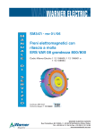
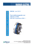
TCS251
PID multi-regulator board with PWM output
Connections and setting
with dancer arm
SERVICE MANUAL
MC557-gb-0506
WARNER ELECTRIC EUROPE - Tél. +33 (0)2 41 21 24 24, Fax + 33 (0)2 41 21 24 00
www.warnerelectric-eu.com
Dancer arm control
Ce mode de fonctionnement vous permet de régler la position du bras danseur et, indirectement, la tension en
ajustant la pression appliquée à l’intérieur du piston du rouleau.
Le régulateur TCS-251 reçoit le signal analogique indiquant la position du rouleau danseur, la vitesse de la
machine et la vitesse de la bobine (ou le diamètre) et puis fournit en sortie 2 signaux analogiques (couple et vitesse)
pour commander un driver (moteur), en conséquence le bras danseur reste toujours à la position désirée (consigne).
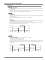
Programming
Une liste de brèves descriptions sur les fonctions de programmation de l'appareil sont donnés ci dessous. Pour
une description détaillée des fonctions de programmation, demander à Warner Electric.
To enter the programming environment, press the
tion ("F.1") will then appear on the display.
key for approximately 3 seconds. The number of the func-
To scroll the programming function menu use the
and
keys.
To modify the parameters belonging to a function call up the number of the desired function on the display,
press the
key and the function value set is displayed. Change the setting to the desired value by
pressing the
and
keys, and then press the
key to confirm.
Operating functions
Function
1
2
3
4
5
6
7
8
9
10
11
12
13
14
15
16
17
18
19
20
21
23
24
Description
Entering the password
Accessing calibration
Setting proportional band in AUTO
Setting integral band in AUTO
Setting derived band in AUTO
Setting proportional band in ACC
Setting integral band in ACC
Setting derived band in ACC
Setting proportional band in DEC
Setting integral band in DEC
Setting derived band in DEC
Setting proportional band in STOP
Setting derived band in STOP
Setting tension when machine is stationary
Emergency stop
Display filter
AIN1 input filter
AIN2 input filter
Setting password
Setting decimal point
Setting tension setpoint
Percentage variation in proportional gain
Percentage variation in derived band
WARNER ELECTRIC EUROPE - Rue Champfleur, B.P. 20095, F - 49182 St Barthélemy d’Anjou Cedex
Value
range
0➛999
*
0➛99.9
0➛9.99
0➛9.99
0➛99.9
0➛9.99
0➛9.99
0➛99.9
0➛9.99
0➛9.99
0➛99.9
0➛9.99
0➛999
0➛999
0➛99
0➛99
0➛99
0➛999
0➛3
0➛FS
0➛100
0➛100
MC557gb- rev 05/06
Factory
setting
0
*
10.0
0.30
7.00
10.0
0.30
7.00
10.0
0.30
7.00
0.0
0.00
0
600
75
10
10
0
0
50
0
0
2/6
Fonctions de calibrages
Function
50
51
52
53
54
55
56
57
60
61
62
63
64
65
67
68
69
70
73
Value
range
*
0➛2
0➛1
0➛1
0➛2
0➛999
*
*
0➛1
0➛1
0➛1
0➛999
0➛DMax
DMin➛DMax
0➛999
1➛999
0➛10
*
0➛1
Description
Function reset
Selecting AIN0 input type
Selecting AIN1 input type
Selecting AIN2 input type
Selecting output type
Setting AIN0 input full scale
Zeroing AIN0 input
Calibrating AIN0 input
Selecting DIN1 input function
Using coil diameter or speed for determining adjustments
Adjusting rewinder or unwinder
Maximum diameter
Minimum diameter
Calibrating diameter
Setting torque saturation constant
Speed for AUTO/STOP switchover
Display brightness
Displaying operating mode
Setting AUTO/STOP switchover mode
Factory
setting
*
0
0
0
0
100
*
*
1
1
0
100
9
50
150
20
2
*
0
To exit the programming environment scroll the function menu until you reach function 73, then press
the
key or move onto function 1 and press the
key.
Fast set up
This section describes the installation and test procedures that must be carried out if you wish to set the instrument up quickly. It also includes the wiring diagrams and a description of how to use the digital inputs.
For more detailed descriptions, please consult Warner Electric.
1. Fit the control device;
2. Make the electrical connections as illustrated in the § Wiring diagrams on page 4.
3. Connect the instrument to a power supply;
4. The word 'HI' should appear on the display and it should get steadily brighter;
5. Enter the programming environment: the number of the function that is currently selected (F. 1) is shown on
the display;
6. Using the
key, select function 2. Press
and the word 'CAL' will appear on the display and flash
three times, then the calibration functions needed for the -02 operating mode fast set up are given in sequence.
7. Function 51 appears on the display. Use this function to select the type of input for the dancer (AIN0).
Press
and the function value set is displayed. Using the
input, to 1 for a 0-5V input and to 2 for a mA input. Press
function.
or
key, set the value to 0 for a 0-10V
to confirm and
to move onto the next
8. Function 55 appears on the display. Use this function to set the position full scale for the dancer, which is
normally set at the factory value (100). Press
and the function value set is displayed.
Using the
or
key, set the value to the desired position full scale. Press
to move onto the next function.
to confirm and
9. Function 56 appears on the display. Position the dancer so that it supplies the maximum voltage (e.g.: 0V).
Press
and the word 'YES' flashes on the display, then the number of the function (F.56) is displayed
again. Press the
key to move onto the next function.
10.Function 57 appears on the display. Position the dancer so that it supplies the maximum voltage (e.g.: 10V).
Press
and the word 'YES' flashes on the display, then the number of the function (F.57) is displayed
again. Press the
key to move onto the next function.
WARNER ELECTRIC EUROPE - Rue Champfleur, B.P. 20095, F - 49182 St Barthélemy d’Anjou Cedex
MC557gb- rev 05/06
3/6
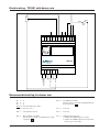
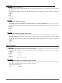
10 K
Electromagnetic Brake
Electric wiring - TCS251 with dancer arm
Po
AOUT1 AOUT0
1
2
0V
3
AIN2
AIN1
4 5
AN0
0V
DIN2
6
7
8
DIN1
DIN0
SW1
Auto/
Stop
DIN0 PWM+ PWM-
9 10 11 12
3
4
5
6
24 VDC
0V
12 VDC
2
Supply
18 VAC/24VDC
1
0V
TCS 251
Recommended setting for dancer arm
F3 = P
F4 = I
F3 = D
Note: You must start with these values
P = 40, I = 0, D = 0
F57 =
Up calibration for AIN0
Turn the sensor to have max voltage between pin
6 and 7 and push
F71 =
0 Not use
F55 =
full scale(often 100%)
F72 =
0 Not use
F56 =
Down calibration for AIN0
Turn the sensor to have 0 volt between pin 6 and
7 and push
F14 =
Holding torque when stop
if F66=0 then PWM output= constant
● if F66=1 then PWM output= last output value
before to go in stop mode
●
WARNER ELECTRIC EUROPE - Rue Champfleur, B.P. 20095, F - 49182 St Barthélemy d’Anjou Cedex
MC557gb- rev 05/06
4/6
Analog and digital I/O descriptions
Digital inputs
Pin: DIN0
Function: AUTO/STOP
It is active if F.73=1.
If the input is in the "HIGH" logic state (+24 Vdc the device switches to the AUTO state, otherwise it is
in the STOP state.
When F.73=0 the switchover between the STOP and AUTO states (and vice versa) takes place automatically
when the line speed goes above (or below) the value set at F.68.
Pin: DIN1
If F.60 = 0
Function: ZERO
If the input is in the "HIGH" logic state (+24 Vdc) the device switches to the ZERO state, zeroing the brake
control output voltage.
N.B.: The ZERO state is applied only if the device is in the STOP state.
If F.60 = 1
Function: ACC
If the input is in the "HIGH" logic state (+24 Vdc) the device switches to the ACC state, performing
adjustments with the set of PID acceleration parameters (F.6, F.7 and F.8).
The following diagram illustrates the correct activation sequence of the digital inputs for passing from the
STOP to the AUTO state, through the acceleration state.
DIN 0
DIN 1
DIN 2
STATE
STOP
ACC
AUTO
Pin: DIN2
If F.60 = 0
Function: ACC or DEC
If the input is in the 'HIGH' logic state (+24Vdc) the device switches:
- to the ACC state, if it was initially in STOP;
- to the DEC state, if it was initially in AUTO.
The following diagram illustrates the correct activation sequence of the digital inputs for passing from the
STOP to the AUTO state, through the ACC state and, vice versa, from the AUTO to the STOP state , through
the DEC state
DIN 0
DIN 1
DIN 2
STATE
STOP
ACC
AUTO
WARNER ELECTRIC EUROPE - Rue Champfleur, B.P. 20095, F - 49182 St Barthélemy d’Anjou Cedex
DEC
STOP
MC557gb- rev 05/06
5/6
Analog inputs
Pin: AIN0
Function: Dancer analog input
This accepts an analog signal proportional to the position of the dancer. It is connected to the dancer position
sensor output.
The type of input accepted can be altered during calibration by changing the software settings; in particular:
If F.51 = 0
0-10V
If F.51 = 1
0-5V
If F.51 = 2
0-20 mA
Pin: AIN1
Function: Line speed analog input
This accepts an analog signal proportional to the machine line speed. It is connected to the output of a dynamo or
of an analog encoder which detects the speed of rotation of the machine MASTER motor.
The type of signal accepted can be altered during calibration by changing the software settings; in particular:
If F.52 = 0
0-10V
If F.52 = 1
0-5V
Pin: AIN2
Function: Coil speed or diameter analog input
This accepts an analog signal proportional to the coil speed (F.60=1) or coil diameter (F.60=0). It is connected to
the analog output of a dynamo which detects the speed of rotation of the coil or of a diameter reader (a Warner Electric
US sensor or probe).
The type of signal accepted can be altered during calibration by changing the software settings; in particular:
If F.53 = 0
0-10V
If F.53 = 1
0-5V
Sorties analogiques
Pin: AOUT0
Function: Analog output for the motor speed command
This supplies an analog speed reference for the motor. It must be connected to the motor driver speed analog input.
The type of signal accepted can be altered during calibration by changing the software settings; in particular:
If F.54 = 0
0-10V
10mA max
If F.54 = 1
-5-+5V
20mA max
If F.54 = 2
4-20mA
Rload = 330 Ohm max
Pin: AOUT1
Fonction: Analog output for the motor torque command
This supplies an analog torque reference for the motor. It must be connected to the motor driver torque analog input,
which allows modulation of the current in the motor armatures.
The analog reference type is:
0-10V
10mA max
WARNER ELECTRIC EUROPE - Rue Champfleur, B.P. 20095, F - 49182 St Barthélemy d’Anjou Cedex
MC557gb- rev 05/06
6/6
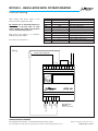
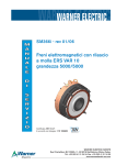
BTCS251 - REGULATOR WITH POTENTIOMETER
Function setting
After wiring, enter these values in the
control. Please respect this order.
Be careful: F72 is overload function; if
the power is off and after on with
some trouble on supply, the function
can be automatically set to 0.
That means the output is in maximum
braking to protect people.
To restart, set the F72 to 1
Function
F3
F4
F5
F14
F53
F55
F56
F57
F64
F63
F66
F72
Value
99.9
0
0
999
0
100
min. volt on AIN0 input
max. volt on AIN0 input
min. volt on AIN2 input
max. volt on AIN2 input
0
1
Description
proportional band
integral band
derived band
Max output adjustment
AIN2 input 0-10 volts
AIN0 full scale
Calibrating min. signal on AIN0
Calibrating max. signal on AIN0
Calibrating min. signal on AIN2
Calibrating max. signal on AIN2
output enable for F14 value
input enable for AIN2 analog signal
LINEAR POTENTIOMETER
Powder brake
10 K
Wiring
BTCS254-10
AOUT1 AOUT0
1
2
0V
3
AIN2
AIN1
4 5
AN0
0V
DIN2
6
7
8
DIN1
DIN0 PWM+ PWM-
9 10 11 12
BTCS 251
+ 5
6
12 VDC
4
0V
0V
3
24 VDC
2
Supply
18 VAC/24VDC
1
Optional supply
BTCS 252
90-260 VAC/24 VDC
WARNER ELECTRIC EUROPE
Rue Champfleur, B.P 20095, F- 49182 St Barthélemy d’Anjou Cedex
Tél. +33 (0)2 41 21 24 24, Fax + 33 (0)2 41 21 24 00 - www.warnerelectric-eu.com
Subject to alteration without prior notice
SM563-gb rev0306
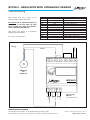
BTCS251 - REGULATOR WITH ULTRASONIC SENSOR
Function setting
After wiring, enter these values in the
control. Please respect this order.
Be careful: F72 is overload function; if
the power is off and after on with
some trouble on supply, the function
can be automatically set to 0.
That means the output is in maximum
braking to protect people.
To restart, set the F72 to 1
Function
F3
F4
F5
F14
F53
F55
F56
F57
F64
F63
F66
F72
Value
99.9
0
0
999
0
100
min. volt on AIN0 input
max. volt on AIN0 input
min. volt on AIN2 input
max. volt on AIN2 input
0
1
Description
proportional band
integral band
derived band
Max output adjustment
AIN2 input 0-10 volts
AIN0 full scale
Calibrating min. signal on AIN0
Calibrating max. signal on AIN0
Calibrating min. signal on AIN2
Calibrating max. signal on AIN2
output enable for F14 value
input enable for AIN2 analog signal
Powder brake
Wiring
SIGNAL
AOUT1 AOUT0
1
2
0V
3
AIN2
AIN1
4 5
AN0
0V
DIN2
6
7
8
DIN1
DIN0 PWM+ PWM-
9 10 11 12
HSCUA-130
OR
HSCUA-140
BTCS 251
+ -
WARNER ELECTRIC EUROPE
Rue Champfleur, B.P 20095, F- 49182 St Barthélemy d’Anjou Cedex
Tél. +33 (0)2 41 21 24 24, Fax + 33 (0)2 41 21 24 00 - www.warnerelectric-eu.com
6
12 VDC
5
0V
4
24 VDC
3
0V
2
Supply
18 VAC/24VDC
1
Optional supply
BTCS 252
90-260 VAC/24 VDC
Subject to alteration without prior notice
SM564-gb rev0306
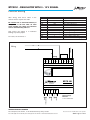
BTCS251 - REGULATOR WITH 0 - 10 V SIGNAL
Function setting
After wiring, enter these values in the
control. Please respect this order.
Be careful: F72 is overload function; if
the power is off and after on with
some trouble on supply, the function
can be automatically set to 0.
That means the output is in maximum
braking to protect people.
To restart, set the F72 to 1
Value
99.9
0
0
999
0
100
min. volt on AIN0 input
max. volt on AIN0 input
min. volt on AIN2 input
max. volt on AIN2 input
0
1
Description
proportional band
integral band
derived band
Max output adjustment
AIN2 input 0-10 volts
AIN0 full scale
Calibrating min. signal on AIN0
Calibrating max. signal on AIN0
Calibrating min. signal on AIN2
Calibrating max. signal on AIN2
output enable for F14 value
input enable for AIN2 analog signal
0V
Powder brake
Wiring
Function
F3
F4
F5
F14
F53
F55
F56
F57
F64
F63
F66
F72
0 - 10 V SIGNAL
AOUT1 AOUT0
1
2
0V
3
AIN2
AIN1
4 5
AN0
0V
DIN2
6
7
8
DIN1
DIN0 PWM+ PWM-
9 10 11 12
BTCS 251
+ 6
12 VDC
5
0V
4
24 VDC
3
0V
2
Supply
18 VAC/24VDC
1
WARNER ELECTRIC EUROPE
Rue Champfleur, B.P 20095, F- 49182 St Barthélemy d’Anjou Cedex
Tél. +33 (0)2 41 21 24 24, Fax + 33 (0)2 41 21 24 00 - www.warnerelectric-eu.com
Optional supply
BTCS 252
90-260 VCA/24 VCC
Sous réserve de modifications sans préavis
SM571-gb rev1006