1
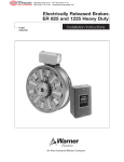
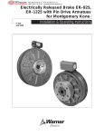
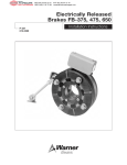
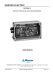
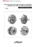
MEX (55) 53 63 23 31
DIST. AUTORIZADO QRO (442) 1 95 72 60
®
MTY (81) 83 54 10 18
[email protected]
Electrically Released Permanent Magnet
Clutch Compatible Modules
Installation Instructions
P-1349
819-0318
EM-50-20 FBC
EM-180-20 FBC
EM-210-20-FBC
5370-169-056
5370-169-057
5371-169-028
Follow Steps 4 and 8 in the Service Manual.
20 FBC-30-B
Warner Electric’s FBC series of Electrically
Released Modules are designed to be used in
clutch-brake combinations only. The FBC
modules can be mounted on a C-face motor
with the proper input module (10 module), and
can also be foot mounted with a 30 Input Clutch
Module and base. The FBC modules include a
spacer for mounting to 10 and 30 clutch
modules. The fail safe brake engages when
power goes off.
10-20 FBC
Reference: Electro-Module Service Manual
P-213.
Mounting Instructions
Follow Steps 1 and 2 in the Service Manual.
Step 3
Assembling two modules. The 20 FBC brake
module may be assembled to the mounted
model 10 motor clutch module as follows:
Reference: Electro-Module Service Manual
P-213.
Mounting Instructions
Follow Step 2 in the Service Manual.
Step 3
Assembling two modules. The 20 FBC brake
module may be assembled to the (30) input
clutch module.
A. Position the modules with the ventilation
holes down when in their normal horizontal
position to prevent foreign matter from falling
into the units.
B. Assemble the 20 FBC brake module to the 30
input clutch module, inserting the spacer
provided between the units. Bolt the modules
together with the long hex head bolts provided.
Follow Step 4 in the Service Manual.
A. Position the modules with the ventilation
holes down when in their normal horizontal
position to prevent foreign matter from falling
into the units.
Step 7
B. Assemble the 20 FBC brake module to the
motor clutch module, inserting the spacer
provided between the (20) and (10) modules.
Bolt the modules together with the long hex
head bolts provided.
A. Mount the modules so that the base is
located below the ventilation holes. A pilot
diameter on the end of each module mates with
pilot diameter on the base.
Warner Electric
Installing the Base Mount. The 20 FBC brake
module and the 30 input clutch module can be
base mounted as follows:
800-825-9050
MEX (55) 53 63 23 31
DIST. AUTORIZADO QRO (442) 1 95 72 60
®
MTY (81) 83 54 10 18
[email protected]
B. Secure the base to the modules with the four
(4) bolts provided.
Control Requirement
Electrically Released Permanent Magnet Brakes
must use one of Warner’s adjustable power
supplies. See the Service Installation sheet
included with the power supply for connection
information.
Note: All Electrically Released Permanent
magnet modules are polarity sensitive.
Therefore, the (+) wire must be connected to
the positive terminal and the (-) wire to the
negative terminal. Potentiometer control will
then provide adjustment for the proper brake
release point.
Switching of clutch and brake with this type of
module should allow both clutch and brake to
be engaged and disengaged simultaneously for
proper operation.
Brake Release Adjustment
Instructions for setting the optimum release
voltage of permanent magnet applied/
electrically released brakes.
The following procedure will
result in the brake releasing and allowing the
load to be free to move. Be sure the load is in
a safe condition before proceeding with this
process.
In a permanent magnet applied/electrically
released brake, the attractive force between the
brake surfaces is created by permanent
magnets. The brake is electrically released by
applying DC power to the electro-magnetic coil
2
Warner Electric • 800-825-9050
in the brake that opposes the permanent
magnets. Electrically released brakes are
polarity sensitive: the positive lead of the power
supply must be connected to the positive lead
of the brake, and the negative lead of the power
supply must be connected to the negative lead
of the brake. The power supply applied to the
brake must also be adjustable so that the
optimum release voltage for each individual
brake can be determined and set.
The following procedure describes how to set
the adjustable power supply to the optimum
release point of the brake. A volt-meter is
required to perform the procedure.
No power is applied to motor
during this procedure. Power normally
supplied by motor to brake control should be
supplied by alternate method.
After control is adjusted per steps below,
brake control may need to be fine tuned
(adjusted) with motor running to compensate
for any changes in supply voltage used.
1. With power off, connect the positive lead of
the power supply to the positive lead of the
brake and the negative lead of the power
supply to the negative lead of the brake.
2. Connect a volt-meter to measure the voltage
applied across the brake.
3. Adjust the power supply to its lowest
possible output, then energize the power
supply only, to apply power to the brake.
4. Starting from the low point, slowly increase
the applied voltage until the brake armature
disengages from the magnet. Note and
record the applied voltage at this point.
819-0318
MEX (55) 53 63 23 31
DIST. AUTORIZADO QRO (442) 1 95 72 60
®
MTY (81) 83 54 10 18
[email protected]
5. Continue to slowly increase the applied
voltage until the armature re-engages the
magnet. If the maximum voltage available
from the supply does not cause the armature
to re-engage, the armature should be
manually assisted into engagement.
Note: If armature needs to be manually
assisted, armature should be pressed on
back side to make contact with friction face
of magnet.
6. With the armature re-engaged, slowly reduce
the applied voltage until the armature
disengages from the magnet. Note and
record the applied voltage at this point.
7. The optimum release point for the brake is
half-way between the two recorded voltage
readings. Adjust the supply to this optimum
release voltage.
Note: The above procedure should be done
by visually watching the armature move and
may be repeated if necessary from Step 1
through Step 7.
If any problems should occur during
adjustments or application questions arise,
please contact Technical Support at 1-800-8259050 Monday through Friday 7:30 a.m. - 4:30
p.m. central time.
Warner Electric • 800-825-9050
819-0318
3
MEX (55) 53 63 23 31
DIST. AUTORIZADO QRO (442) 1 95 72 60
®
MTY (81) 83 54 10 18
[email protected]
Warranty
Warner Electric LLC warrants that it will repair or replace (whichever it deems advisable) any
product manufactured and sold by it which proves to be defective in material or workmanship
within a period of one (1) year from the date of original purchase for consumer, commercial or
industrial use.
This warranty extends only to the original purchaser and is not transferable or assignable without
Warner Electric LLC’s prior consent.
Warranty service can be obtained in the U.S.A. by returning any defective product, transportation
charges prepaid, to the appropriate Warner Electric LLC factory. Additional warranty information
may be obtained by writing the Customer Satisfaction Department, Warner Electric LLC, 449
Gardner Street, South Beloit, Illinois 61080, or by calling 815-389-3771.
A purchase receipt or other proof of original purchase will be required before warranty service is
rendered. If found defective under the terms of this warranty, repair or replacement will be made,
without charge, together with a refund for transportation costs. If found not to be defective, you
will be notified and, with your consent, the item will be repaired or replaced and returned to you
at your expense.
This warranty covers normal use and does not cover damage or defect which results from
alteration, accident, neglect, or improper installation, operation, or maintenance.
Some states do not allow limitation on how long an implied warranty lasts, so the above limitation
may not apply to you.
Warner Electric LLC’s obligation under this warranty is limited to the repair or replacement of the
defective product and in no event shall Warner Electric LLC be liable for consequential, indirect,
or incidental damages of any kind incurred by reason of the manufacture, sale or use of any
defective product. Warner Electric LLC neither assumes nor authorizes any other person to give
any other warranty or to assume any other obligation or liability on its behalf.
WITH RESPECT TO CONSUMER USE OF THE PRODUCT, ANY IMPLIED WARRANTIES WHICH
THE CONSUMER MAY HAVE ARE LIMITED IN DURATION TO ONE YEAR FROM THE DATE OF
ORIGINAL CONSUMER PURCHASE. WITH RESPECT TO COMMERCIAL AND INDUSTRIAL
USES OF THE PRODUCT, THE FOREGOING WARRANTY IS IN LIEU OF AND EXCLUDES ALL
OTHER WARRANTIES, WHETHER EXPRESSED OR IMPLIED BY OPERATION OF LAW OR
OTHERWISE, INCLUDING, BUT NOT LIMITED TO, ANY IMPLIED WARRANTIES OF
MERCHANTABILITY OR FITNESS.
Some states do not allow the exclusion or limitation of incidental or consequential damages, so
the above limitation or exclusion may not apply to you. This warranty gives you specific legal
rights and you may also have other rights which vary from state to state.
Changes in Dimensions and Specifications
All dimensions and specifications shown in Warner Electric catalogs are subject to change without
notice. Weights do not include weight of boxing for shipment. Certified prints will be furnished
without charge on request to Warner Electric.
Warner Electric LLC
449 Gardner Street • South Beloit, IL 61080
815-389-3771 • Fax: 815-389-2582
www.warnerelectric.com
P-1349 819-0318 6/05
Printed in USA