1
BodyElectrical
\
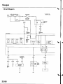
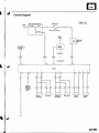
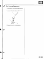
Body Electrical
SpecialTools
GeneralTroubleshooting
tntorrnaiion.'......
22,3
RelayandControlUnit Locations.....22-7
Connectors
and Harnesses
22-13
Fuse/Relay
Boxes...............................
22-44
PowerDistribution.............................
22-46
GroundDistribution...........................
22-4A
Under-dash
Fuse/Relay
Box ..............
22-49
Battery ..............
Relays................
*lgnitionSwitch ..............
22-50
22-51
22-53
*Gauges
C o m p o n e nLto c a t i o Inn d e x . . . . . . . . . . . . . . . . 22-54
.......
S e l f - d i a g n o sPt irco c e d u r .e. . . . . . . . . . . . . . . . . 22-56
........
CircuitDiagram
22-54
G a u g eB u l bR e p l a c e m e n. .t . . . . . . . . . . . . . . . .22
. . . .63
....
GaugeAssemblyReplacement
22-64
CoolantTemperature
......
G a u g eT r o u b l e s h o o t i n.g. . . . . . . . . . . . . . . . 22-64
VehicleSpeedSignalCircuit
Troubleshooting
22-65
VSSReplacement
22 61
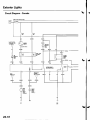
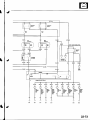
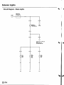
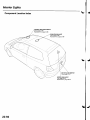
ExteriorLights
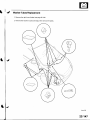
C o m p o n e nLto c a t i oInn d e x . . . . . . . . . . . . . . . . 22-68
.......
C i r c u iD
t iagram
22--71
DaytimeRunningLightsControi
U n i tI n p u tT e s t( C a n a d a .) . . . . . . . . . . . . . . . .22-7
. . . . .6. .
H e a d l i g hAtd , u s t m e n .t . . . . . . . . . . . . . . . . . . 22-74
H e a d l i g hRr e p l a c e m e n. .t. . . . . . . . . . . . . . . . . . .22-79
.........
CombinationLightSwitch
Test/Replacement
22-AO
B u l bR e p l a c e m e n t
22-41
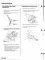
T a i l l i g hRt e p l a c e m e n. .t . . . . . . . . . . . . . . . . . . . .22-82
....
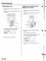
HighMountBrakeLightReplacement......22-42
LicensePlateLightReplacement..............
22-43
S i d eM a r k e L
r i g h tR e p l a c e m e n. .t. . . . . . . . . .22-43
....
BrakePedalPositionSwitchTest ..............
22-44
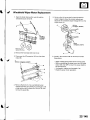
SideTurn SignalLightReplacement........22-84
Turn Signal/Hazard
Flasher System
C o m p o n e nLto c a t i o Inn d e x . . . . . . . . . . . . . . . . 22-85
.......
C i r c u iD
t iagram
22 A6
Turn Signal/Hazard
RelaylnputTest ........22-87
HazardWarningSwitchTest
22-88
Entry Lightscontrol system
ComponentLocationIndex .......................
22-89
C i r c u iD
t iagram
. . . . . . . 2. .2 9 0
lgnitionKeySwitchTest .....................,......
22-9'l
l g n i t i o nK e yL i g h tT e s t . . . . . . . . . . . . . . . . . . . . . 2
. .2. .-.9. .1. . .
C o n t r oUl n i tI n p u tT e s t . . . . . . . . . . , . . . . . . . . . . 2
. .2. .9. 2
.....
InteriorLights
ComponentLocationIndex .......................
22-94
CircuitDiagram
.........22-95
CeilingLighVSpotlights
T e s V R e p l a c e m e. n
. .t. . . . . . . . . . . . . . . . . . . . .2. .2. -. .9.6. . . . .
RearCeilingLightTesVReplacem
ent ........22-96
CargoAreaLightTest/Replacem
ent .........22-97
HatchLatchSwitchTest ..,..,.......................
22-97
*Audio System
ComponentLocationIndex .......................
22-98
CircuitDiagram
.........22,99
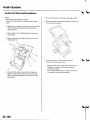
AudioUnit Removal/lnstallation
...............
22-1OO
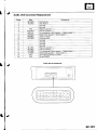
Audio Unit ConnectorReplacement.........22-101
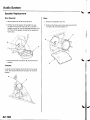
SpeakerReplacement................................
22-102
RoofAntennaRep1acement
....................-..
22-103
Rear Window Defogger
ComponentLocationIndex ...........
22-104
C i r c u iD
t i a s r a m. . . . . . . . . . . . . . . . . . . . . : : : : : . : :22-105
.::.
FunctionTest
D e f o g g eW
r i r eR e p a i r. . . . . . . . . . . . . . . . . . . . . . .22-106
..........
N o i s eC o n d e n s eCra p a c i t y T e s. t. . . . . . . . . . .22-107
....
Moonroof
C o m p o n e nLto c a t i o Inn d e x . . . . . . . . . . . . . . . . 2. .2. .-.1. .O B
CircuitDiagram
.........22-109
MoonroofControlUnitInputTest .............
22-'l10
S w i t c hT e s V R e p l a c e m e. n
. .t. . . . . , . . . . . , . . .2. .2. .- .11. .2.
MotorTest
.................
22-112
LimitSwilchTest
......22-'l'13
Auto-stopSwitchTest ................................
22-113
PowerMirrors
ComponentLocationIndex .......................
22-114
CircuitDiagram
.........22-115
FunctionTest
.............
22-116
P o w e rM i r r o rS w i t c hT e s t . . . . . . . . . . . . . . . . . . 2. .2. .-.l .l .7.
PowerMirrorActuatorTest .......................
22-117
PowerMirrorActuatorReplacement........22-11A
* Horns
ComponentLocationIndex .......................
22-120
CircuitDiagram
.........22-121
H o r nT e s V R e p l a c e m e. n
. .t. . . . . . . . . . . . . . . . .2. .2. -. .1. 2. -2.
HornSwitchTest
.,....22-122
\
PowerWindows
22 124
ComponentLocationIndex ..........
::::.:
c i r c u i tD i a g r a m. . . . . . . . . . . . . .......... . . . . : . : : : : .22-125
M a s t eS
r w i t c hI n p u tT e s t . . . . . . . . . . . . . . . . . . .22-126
........
22-128
MasterSwitchTest
......
D r i v e r 'W
s i n d o wM o t o rT e s t . . . . . . . . . . . . . . .22-129
Passenger's
WindowSwitchlnputTest ... 22- t30
Passenger's
WindowSwitchTest .............
22-132
22 132
Passenger's
WindowMotorTest ..............
22-133
lMaster
SwitchReplacement......................
Passenger's
WindowSwitch
22-133
Replacement
Wipers/Washers
22-134
ComponentLocationIndex .......................
C i r c u iD
t iagram
RearWindowWiperIntermiftent
........
C o n t r oU
l n i tI n p u tT e s t . . . . . . . . . . . . . . . . . . .22-138
Wiper/Washer
Switch
22-140
TesVReplacement
..
C o n t r oU
l n i tI n p u tT e s t . . . . . . . . . . . . . . . . . . . . . .2.2. .-.1. .4. 1
WiperMotorTest
22-143
22-144
WasherMotorTest
WasherFluidLevelSwitchTesV
.......
R e p l a c e m e(nCt a n a d a.l . . . . . . . . . . . . . . . . . .22-144
WindshieldWiperMotor Replacement.... 22-145
RearWindowWiperMotor
Replacement
22-146
....
W a s h eR
r e s e r v oR
i r e p l a c e m e n. .t. . . . . . . . . .22-146
. . . 147
...
W a s h eTr u b e sB e p l a c e m e n. .t. . . . . . . . . . . . . .22
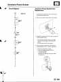
Accessory Power Socket
.........22-149
CircuitDiagram
AccessoryPowerSocket
. .t. . . . . . . . . . . . . . . . . . . . .2. .2. .- .14. .9. . . .
T e s V R e p l a c e m e. n
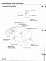
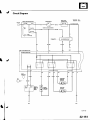
Keyless/Power Door Lock System
22-150
ComponentLocationIndex .......................
.........22-151
CircuitDiagram
22-153
KeylessReceiver
Unit InputTest ...............
22-155
ControlUnit InputTest ...............................
D o o rL o c k A c t u a t o r T e s. .t. . . . . . . , . . . . . . . , . .2, 2. ,-.1. .5. .8
. .5. .9
H a t c hL o c k A c t u a t o r T e s. .t. . . . . . . . . . . . . . . . .2. .2. -. 1
22-160
DoorLockKnobSwitchTest ......................
22-160
DoorLockSwitchTest ................................
.......22-161
TransmitterTest
T r a n s m i t t ePrr o g r a m m i n .g. . . . . . . . . . . . . . . . .2. 2. .-.1. .6. 1
lmmobilizerSystem
22-162
componentLocationIndex ...........
...
S y s t e mD e s c r i p t i o .n. . . . . . . . . . . . . . . :. . . : . . : . :22-163
22-164
CircuitDiagram
Troubleshooting
lmmobilizerControlUnit
- R e c e i v eRre p l a c e m e n. .t. . . . . . . . . . . . . . . . .22-167
........
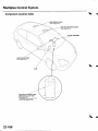
Multiplex ControlSystem
22,164
ComponentLocationIndex ...........
:.:..:.::.:
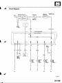
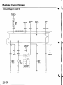
c i r c u i tD i a g r a m. . . . .... . . . . . . . . . . . . . . . . . . . . . . :22-169
22-17'l
SvstemDescriDtion
22,112
Troubleshooting
M u l t i o l eC
x o n t r oUl n i tI n D uTt e s t . . . . . . . . . . .2.2. - 1 7 5
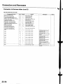
BodyElectrical
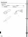
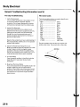
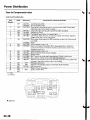
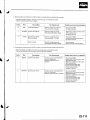
SpecialTools
Ref. No.
Q)
o)
o
Tool Number
07wAz-001010A
O7LAJ-PT3O2OA
07TAz-001020A
Description
MPCSServiceConnector
Test Harness
BackProbeAdaotet
1
1
1
@
22-2
Otv
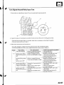
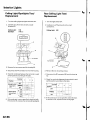
GeneralTroubleshootingInformation
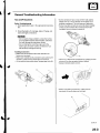
Tipsand Precautions
Before Troubleshooting
1. Checkapplicablefuses in the appropriatefuse/relay
oox.
Some connectorshave a clip on their side used to
attachthem to a mount bracketon the body or on
a n o t h e rc o m p o n e n tT. h i sc l i p h a sa p u l lt y p e l o c k .
Some mountedconnectorscannot be disconnected
unlessyou first releasethe lock and removethe
connectorfrom its mount bracket(A).
2. Checkthe batteryfor damage.stateof charge,and
cleanand tight connections.
. Do not quick-chargea batteryunlessthe battery
ground cable has been disconnected,otherwise
you will damagethe alternatordiodes.
. Do not attemptto crankthe enginewith the
batteryground cable looselyconnectedor you
w i l l s e v e r e l yd a m a g et h e w i r i n g .
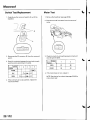
Handling Connectors
. Make surethe connectorsare clean and have no
l o o s ew i r e t e r m i n a l s .
. Make sure multiplecavity connectorsare packedwith
dielectricgrease(exceptwatertight connectors).
. All connectorshave push-downreleasetype locks(A).
Nevertry to disconnectconnectorsby pulling on their
wires; pull on the connectorhalvesinstead.
Alwavs reinstallDlasticcovers,
Beforeconnectingconnectors,make sure the
terminals(A) are in placeand not bent.
(cont'd)
22-3
BodyElectrical
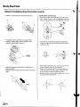
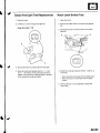
GeneralTroubleshootingInformation(cont'd)
Checkfor looseretainer(A)andrubberseals(B).
The backsof some connectorsare packedwith
dielectricgrease.Add greaseif necessary.lf the
greaseis contaminated,replaceit.
HandlingWires and Harnesses
. Securewires and wire harnessesto lhe frame with
their respectivewire ties at the designatedlocations.
. Removeclips carefully;don't damagetheir locks(A).
S l i p p l i e r s( A ) u n d e rt h e c l i p b a s ea n dt h r o u g ht h e
hole at an angle,then squeezethe expansiontabs to
r e l e a s et h e c l i p .
J
lnsertthe connectorall the way and make sure it is
securelvlocked.
Positionwires so that the open end of the cover faces
oown.
After installingharnessclips, make sure the harness
doesn't interferewith any moving pans.
Keepwire harnessesaway from exhaustpipes and
other hot parts,from sharp edgesof bracketsand
holes,and from exposedscrewsand bolts.
Seatgrommets in their grooves properly{A). Do not
leavegrommets distorted(B).
| . , ./ f
.ll
----E;
'l/ F.
I
22-4
t/
lwtl"//
\--------\
tflr'---'..-
It
Testingand Repairs
. Do not usewires or harnesseswith brokeninsulation.
Replacethem or repairthem by wrappingthe break
withelectricaltape.
. After installingparts,make surethat no wires are
o i n c h e du n d e rt h e m .
. When using electricaltestequipment,followthe
manufacturer'sinstructionsand those describedin
t h i sm a n u a l .
. l f p o s s i b l ei ,n s e r t t h ep r o b eo f t h e t e s t e r f r o m t h ew i r e
side (exceptwaterproofconnector).
UsebackDrobeadaotor07TM-0010204.
Referto the instructionsin the HondaTerminal Kit for
identificationand reolacementof connectorterminals.
( c o n td )
22-5
BodyElectrical
GeneralTroubleshootingInformation(cont'dl
Five-stepTroubleshooting
'1.
Verify The Complaint
T u r n o n a l l t h e c o m p o n e n t si n t h e p r o b l e mc i r c u i t
to verify the customercomplaint.Note the
symptoms.Do not begin disassemblyor testing
until you have narroweddown the problem area.
2. AnalyzeThe Schematic
Look up the schematicfor the problem circuit.
Determinehow the circuit is supposedto work by
tracingthe currentpathsfrom the power feed
through the circuitcomponentsto ground. lf
severalcircuitsfail at the same time, the fuse or
g r o u n di s a I i k e l yc a u s e .
Basedon the symptoms and your understandingof
the circuitoperation,identifyone or more possible
causesof the problem.
3. lsolateThe ProblemBy TestingThe Circuit
Make circuitteststo checkthe diagnosisyou made
i n s t e p2 . K e e pi n m i n d t h a t a l o g i c a ls, i m p l e
procedureis the key to efficienttroubleshooting.
Testfor the most likelycauseof failure first, Try to
make tests at pointsthat are easilyaccessible.
4. Fix The Problem
Oncethe specificproblem is identified.make the
repair.Be sure to use propertools and safe
proceoures.
5. Make Sure The CircuitWorks
Turn on all componentsin the repairedcircuit in all
modes to make sure you've fixed the entire
problem.lf the problemwas a blown fuse, be sure
to test all of the circuitson the fuse. Make sure no
n e w p r o b l e m st u r n u p a n d t h e o r i g i n a p
l roblem
does not recur.
22-6
Wire Color Codes
The following abbreviationsare usedto identifywire
colors in the circuitschematics:
w H T . . . . . . . . . . . . . . . . . . . . , . , . White
............
Y E L . . . . . . . . . . . . . . . . . . . . . . , , .Y. .e.l.l .o. w
,......
B 1 K . . . . . . . . . . . . . . . . . . . . . . . . . . .B
. .l.a. .c. k. . . . .
B L U. . . . , . . . . . . . . . . . . . . . . . . . . . . .B. .l.u. .e. . . .
G R N . . . . . . . . . . . . . . . . . . . . . . . .G
. .r.e. .e.n. . . . . . .
R E D. . . . . . . . . . . . . . . . . . . . . . . . . . . .Red
........,
o R N . . . . . . . . . . . . . . . . . . . . . . . . Orange
.............
P N K . . . . . . . . . . . . . . . . . . . . . . . .P
. .i,n. k. . . . . . . . .
B R N . . . . . . . . . . . . . . . . . . . . . . . .Brown
.............
G R Y . . . . . . . . . . . . . . . . . . . . . . . .Gray
............,
P U R . . . . . . . . . . . . . . . . . . . . . . . .P
. .u. .r .p.l.e. . . . . .
1 T 8 1 U . . . . . . . . . . . . . . . . . . . . . Light
. . . . . ,Blue
.....
1TGRN....................L
. .i.g. h
. .G
t. ,r.e. .e n
The wire insulationhas one color or one color with
anothercolor stripe.The secondcolor is the stripe.
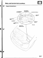
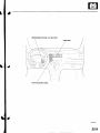
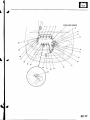
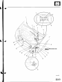
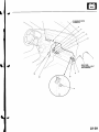
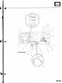
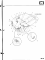
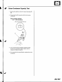
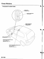
Relayand Control Unit Locations
EngineCompartment
BLOWERMOTORRELAY
RADIATORFAN
RELAY
HORNRELAY
CONDENSERFAN
RELAY
ELDUNIT
UNDER-HOOD
FUSE/RELAY
BOX
\...
,-:1-'...
22-7
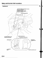
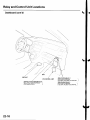
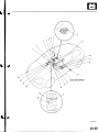
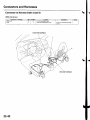
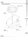
Relayand GontrolUnit Locations
Dashboard
RUNNINGLIGHTSEELAYlCanada)
_DAYTIME
lWirecolorsrRED,RED/YEL,I
andRED/8LU
LRED/BLK
I
BEAMCUTRELAYlcanada) _
_LOW
REDMHT,
RED/BLK,
colors:
lWire
I
andRED/BLU
LBEDA/EL
I
KEYLESSRECEIVER
UNIT
CRUISECONTROLUNIT
'
':
'-.:-
..? ;,
POWERWINOOW RELAY
TURN SIGNAL/HAZARDRELAY
TAILLIGHTRELAY
;
.[:_- -
-l:r
UNDER.DASH
FUSE/RELAY
BOX
--
MULTIPLEXCONTROLUNIT
22-8
(cont'd)
22-9
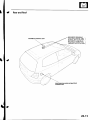
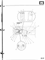
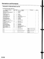
Relayand Control Unit Locations
a
Dashboard(cont'd)
L
\
SRSUNIT
EPSCONTROLUNIT
AIR/FUEL
RATIOSENSOR
RELAY
[WirecolorsrWHT,WHT/RED, I
OBNandBLK/ORN
I
22-10
PGM.FIMAINRELAY1
lWirecolors:YEUBLK,
WHT/BLKand RED/YEL
LWHT/BLK,
PGM.FIMAN RELAY2
fwirecolors:YEUBLK,
I
YEUBLKand GRN/YELI
LYEUGRN,
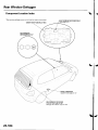
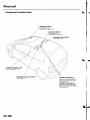
Rearand Roof
OPENRELAY MOONROOF
Wirecolors:GRNI/EL,
GRN, I
BLKandYEL/GRNI
LRED/YEL,
MOONROOF
CLOSERELAY
GRN, l
fwire colors:GRN/BLK,
BLKand YEL/GRNI
IGRN,AtVHT,
REARWINDOWWIPERINTERMITTENT
CONTBOL
UNIT
22-11
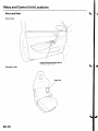
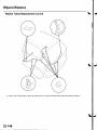
Relayand ControlUnit Locations
Door and Seat
Driver'sDoor:
l\:
].\
POWERWINDOWMASTERSWITCH
lHasbuilt-incontrolunit)
Passenger's
Seat:
22-12
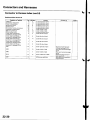
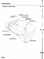
Gonnectors
and Harnesses
a
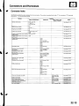
GonnectorIndex
"G" for ground
ldentification
numbershavebeenassigned
to in-lineconnectors.
The numberis preceded
by the letter"C" for connectors,
terminalsor "T" for non groundterminals.
Hamess
Location
EngineCompartment
Dashboard
Others{Floor,Door,
Trunk.and Roo{l
Not€s
Startersubharness
C 1 0 2a n dC 1 0 3
T1 andT2
T 1 0 1a n dT 1 0 2
(seepage22-15)
Batterygroundcable
T3
G'l and ( T4
{seepage22-l!)
Enginegroundcable
{seepage22-14)
Enginewire harness
C l 0 l t h r o u g hC 1 0 4
G1 0 1
Enginecompartment
wire harness G201andG202
{riohtbranchi
Enginecompartment
wire harness G301
(leftbrench)
Enginecompartment
wire harness
(dashboard)
(seepage22 16)
(seepage22 18)
(seepage22 18)
(seepage22-18)
c401
C451and C452
C501throughC503
c551
c851
G402
EPSsubharness
C 1 5 1a n d C 1 5 2
G'151
\seepage22 241
Dashboard
wire harness
A
lleftbranch)
C504throughC510
G501andG503
(seepage22-26)
L e f ts i d et u r n s i g n a l l i g h t
c506
(seepage22-26)
Dashboard
wire harness
A
(rightbranch)
C50lthroughC503
C 5 l l t h r o u g hC 5 1 5
C852andC853
G502
(seepage22-26)
lseepage22-26)
Rightside turn si9nal light
sub harness
Dashboard
wire harnessB
ECMwire harness
(seepage22-30)
C40lthrough
C403
c510
G40l
c101
cl52
C451
through
C453
c511
{seepage22-32}
G451
Floorwireharness(frontside)
C402
andC403
c453
C508
andC509
c512
G551
(see page 22'34)
Floorwire harness(rearside)
C553and C554
(seepage22-34)
Roo{wire harness
Hatchwire harness
Driver'sdoorwire harness
c507
C553andC554
C504andC505
5 1 4a n dC 5 1 5
)552
(seepaqe22-38)
c851 rhrouoh c853
( s e ep a q e 2 2 . 4 3 i
C 5 5 1a n . l C 5 5 ?
P a s s e n q e r ' sd o o r w i . e h a r n e s s
T eh a r n e s s
/C wire harness
( s 6 ep a q e 2 2 ' 3 9 )
(see paqe 22-40)
( s e eo a o e 2 2 - 4 1
(seeoaqe22-42i
22-13
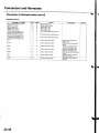
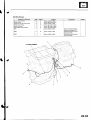
and Harnesses
Connectors
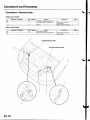
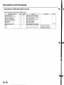
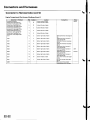
Gonnectorto Harnesslndex
BatteryGroundCable
Connectoror Terminal
Cavities
T3
2
Location
Left side of enqinecompartment
Left side of enginecompartment
Batterv
Connectsto
Notes
Bodygroundviabattery
qroundcar)le
B a t t e r vn e o a t i v et e r m i n a l
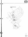
EngineGround Cable
r4
Connectoror Terminal
Cavities
5
4
focation
Riohtsideof enoine
Rightsideof enginecompartment
Connec{sto
Bodygroundviaengine
ENGINEGROUNDCABLE
BATTERYGROUNDCABLE
\.....
22-14
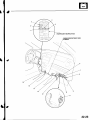
Notes
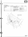
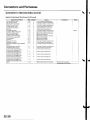
StarterSubharness
Connectoror Terminal
Alternator
Knocksensor
Startersolenoid
c102
Ret
10
8
5
7
Cavities
4
1
1
6
c103
6
1
T1
2
T101
4
1
I
r2
r102
Location
Connoc,ts
to
Right side of eng;necompartment
Front of engine
Middle of enginecompartment
Front of enginecompartment
F r o n t o f e n g a n ec o m p a r t m e n t
L€tt sideof enginecompartment
Middleor enoinecomDanment
Under-hood
fuse/relay
box
Alternator
Batterv
Notes
Enginewire harness(see
page22 16)
Enginewire harness(see
o a a e2 2 - 1 6 )
Underhoodfuse/relay
box
Stanermotor
Battervpositiveterminal
STARTERSUB HARNESS
22-15
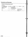
Connectorsand Harnesses
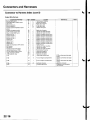
Connectorto HarnessIndex(cont'dl
EngineWireHarness
position(CMP)sensor
Camshaft
Lllr sensor
EC[,4connectorA
ECI/lconnectorB
(ECT)
Enginecoolanttemperature
sensor
Engineoil pressure
switch
EVAPcanisterpurgevalve
ldleair control(lAC)valve
lgnitioncoilNo. l
lgnitioncoilNo.2
lgnitioncoilNo.3
lgnitioncoilNo.4
IniectorNo. 1
InlectorNo.2
IniectorNo.3
IniectorNo.4
Intakeairtemperature
{lAT)sensor
2
3
3
24
2
28
18
4
5
6
7
25
24
20
19
12
TDCsensor
Throttleposition(TP)sensor
Vehiclespeedsensor(VSSI
VTCoil controlsolenoidvalve
VTECoil pressureswitch
VTECsolenoidvalve
c 101
8
11
10
27
29
30
3
c102
22
1
2
3
3
3
3
3
2
2
2
2
2
3
3
3
2
2
2
20
Transmission
housing
Leftsideof engine
Rightsideofengine
Underglovebox
Underglovebox
Leftside of engine
BightsideoI engine
Leftside of intakemanifold
Left sideof intakemanifold
Middleof enginecompartment
Middleof enginecompartment
Middleof enginecompartment
Middleof enginecompartment
Middleof enginecompartment
Middleof enginecompartment
Middleof enginecompartment
Middleof enginecompanment
Leftsideof intakemanifold
Leftsideof engine
Left side of intakemanifold
housing
Transmission
Rightsideo{ engine
Rightsideof engine
Rightsideof engine
Underrightsideof dash
Frontof enginecompanment
Frontof enginecompartment
22-16
ECMwire harness{seepage
22-321
(seepage
Startersubharness
22-15)
(seepage
Startersubharness
22 151
....-
10
11
13
14
22-17
Connectorsand Harnesses
Connectorto HarnessIndex{cont'dl
EngineCompartmentWire Harness(Rightbranch)
Connsctoror Terminal
ABSmodulator-control
unit
Bearwasher
motor
RightfrontABSwheelsensor
Rightfrontairbags€nsor
Bightfrontparkinglight
Rightfrontsidemarkerlight
Rightfrontturn signallight
Rightheadlight
Righthorn
wash€rfluidlevelswitch
Windshield
washermotor
G201
G202
Cavitiss
8
12
1
10
11
2
7
6
2
2
2
2
2
2
I
2
2
Location
Bightsideo{ enginecompartment
Behindrightsideof {rontbumper
Rightsideot enginecompartment
Behindrightsideof frontbumper
Behindrightheadlight
Behindrightsideof Jrontbumper
Behindrightheadlight
Behindrightheadlight
Behindfrontbumper
Behindrightsideof trontbumper
Behindriohtsideof frontbumoer
Behindrightsideof trontbumper
Behindrightsideof Jrontbumper
Connectsto
Notes
Canada
Bodygroundvia€ngine
compartment
wtreharness
Bodygroundviaengine
.omnerhent
wire harness
\
22-18
ENGINECOMPARTMENT
WIRE
HARNESS
(cont'd)
22-19
Connectors
and Harnesses
Connectorto HarnessIndex (cont'dl
EngineCompartmentWire Harness(Left branch)
AirJuel(A,,/F)
ratiosensor
Brakefluidlevelswitch
Condenser
fan motor
Cruisecontrolactuator
ELDunit
Foglightconnector
LeftfrontABSwheelsensor
Leftfrontairbagsensor
Leftfrontparkinglight
Leftfrontsidemarkerlight
Leftlrontturnsignallight
Leftheadlight
Lefthorn
Radiatorfan motor
Radiator
fan switch
Secondary
heatedoxygen(SHO2S)
Testtachometer
connector
Windshield
wipermotor
Under'hood
fuse/relay
box
connector
A {seepage22-44)
Under-hood
f use/relay
box
connectorB (seepage22-44)
Underhoodfuse/relay
box
connector
C (seepage22-44)
Underhoodfuse/relay
box
D (seepage22 44)
connector
fuse/relay
Under-hood
box
24
22
2
2
25
1
9
2
2
4
3
,l
3
4
Frontof enginecompanment
Leftsideof enginecompartment
Leftsideof enginecompartment
Leftsideo{ enginecompartment
Frontof enginecompartment
Underrightsideof cowlcover
Under'hood
f use/relay
box
Leftsideof enginecompartment
Leftsideof enginecompanment
Behindleftsideof frontbumper
Behindleftheadlight
Behindleftsideof frontbumper
Eehindleftheadlight
Behindleftheadlight
Behindfrontbumper
Leftsideof enginecompartment
Frontof enginecompartment
Leftsideof enginecompartment
11
7
2
5
2
Leftsideof enginecompanment
L.Jnder
leftsideof cowlcover
L.Jnder
hoodfuse/relay
box
I
5
L.Jnder
hoodfuse/relay
box
10
12
L.Jnder'hood
f use/relay
box
12
17
13
20
21
23
l
2
2
2
2
2
3
l
2
2
5
underhoodfuse/relay
box
6
fuse/relay
Under-hood
box
\
22-20
l'
\-
ENGINECOMPARTMENTWIRE
HARNESS
(conr'd)
22-21
and Harnesses
Connectors
Connectorto HarnessIndex (cont'd)
EngineCompartmentWire Harness(Dashboard)lcont'dl
Connectoror Terminal
Cavities
Location
1
Undermaddle
of dash
12
Underleftsideof dash
Foglightconnector
Under'dash
fuse/relay
box
connector
F (seepage22-45)
Underdash
fuse/relay
box
G (seepage22-45)
connector
Underdash
fuse/relay
box
connector
H (seepage22'45)
fuse/relay
Under-dash
box
connector
| (seepage22'45)
Under-dash
fuse/relay
box
connector
J (seepage22-45)
c151
c401
1
Underrightsideot dash
c451
I
Underrightsideot dash
c452
9
UnderrightsideoJdash
c501
10
'10
UnderrightsideoI dash
c502
6
4
Underrightsideol dash
c502
6
8
UnderrightsideoJdash
5
UnderrightsideoJdash
10
Undermiddleof dash
1
Underrightsideof dash
5
5
10
Underleftsideof dash
3
Underleftsideof dash
2
5
Underleftsideof dash
3
8
Underleftsideol dash
12
2
Underrightsideof dash
c503
c851
'14
G402
1' I
Connectsto
EPSsubharness
{seepage2224)
wire harnessB
Dashboard
(seepage22-30)
ECMwire harness(seepage
22-321
ECMwire harness(seopage
22 32)
Dashboard
wire harnessA
(seepage22-26)
Dashboard
wire harnessA
USA
lsee page 22-261
Dashboard
wire harnessA
Canada
(seepage22-26)
Dashboard
wire harnessA
(seepage22-26)
Floorwireharness(seepage
22-34l'
,VCwire harnesslsee page
22-43\
Eodygroundviaengine
..mdarlma.t
22-22
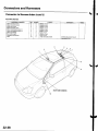
Notes
Oplion
w,rc harncss
BOX
FUSE/RELAY
UNDER-DASH
WIRE
ENGINECOMPARTMENT
D
'
-
' 1_-1.:,
-.,.i
ifa.: ,, ..j
,
. -,,
-g'-.t
';.-a
22-23
Connectorsand Harnesses
Connectorto Harnesslndex (cont'dl
EPSSubharness
Connectoror Terminal
EPScontrolunitconnectorA
EPScontrolunitconnectorB
EPScontrolunitconnector
C
EPSmotor
EPStorquesensor
c151
2
,l
3
1
6
c152
4
G151
5
22-24
Cavities
2
2
20
2
6
2
I
Location
Underrightsideofdash
Underrightsideof dash
Underrighrsideof dash
Middleof enginecompanment
Middleof enginecompartment
Underrightsideof dash
Underrightsideof dash
Connectsto
Enginecompartment
wire
harness(seepage22-18)
ECI\,4
wire harness(seepage
22-321
aodygroundvia EPS
Notes
EPSSUB HARNESS
22-25
Connectorsand Harnesses
Connectorto HarnessIndex (cont'd)
DashboardWire HarnessA {Leftbranchl
Connectoror Terminal
Accessorypower socket
Audioantenna
Brakepedalpositionswitch
Clutchinterlockswitch
Clutchpedalpoistionswitch
Cruisecontrolunit
Cruisemainswitch
Daytimer!nning lightscontrolunit
Daytimerunninglightsrelay
Gaugeassembly
connector
A
GaugeassemblyconnectorB
Hazardwarningswitch
Heatercontrol panelconnectorA
Heatercontrol panelconnectorB
HVACpush switch assembly
Keyless
receiverunit
Low beamcut relay
Optionalsecurityconnector
Powermirrorswitch
Under-dash
fuse/relay
box
connector
K (seepage22-45)
Under'dashfuse/relaybox
L {seepage22-45}
Underdashfuse/relay
box
connectorM lsee page22'45)
Under-dash
fuse/relay
box
connectorN (seepage22-45)
UndeFdash
fuse/relay
box
connector
O (seepage22-45)
UndeFdash
fuse/relay
box
connectorY(seepage22 45)
c504
22
2
26
30
29
6
28
I
8
20
11
18
19
10
5
3
27
,I4
2
2
4
2
2
14
5
14
4
22
22
10
22
'14
10
5
5
16
13
17
Undermiddleof dash
Underleftsideof dash
] Underleftsideof dash
] Underleftsrdeof dash
| Underleftsideof dash
I Underleftsideof dash
Underleftsideof dash
Underlettsideof dash
Underlettsideof dash
I Behindgaugeassembly
i Behindgaugeassembly
Behindhazardwarnningswitch
Behindheatercontrolpanel
Behindheatercontrolpanel
] BehindHVACswitchassembly
I Undermiddleof dash
lUnderleftsideofdash
Underlefrsideof dash
UnderleftsideoI dash
ln the under-dash
fuse/relay
box
l0
In the under-dash
fuse/relay
box
12
ffi
Canada
Canada
In the undeFdash
fuse/relay
box
In the underdashfuse/relay
box
12
11
Inthe under-dash
fuse/relay
box
L
In the under-dash
fuse/relay
box
Underleftsideof dash
c505
Underleftsideot dash
c506
34
Underleftsideof dash
c507
1
Underleftsideof dash
c508
Undermiddleof dash
c509
24
c510
25
G501
1
Undergaugeassembly
G503
21
Underleftsideof dash
Undermiddleof dash
12
Undermiddleol dash
Driver'sdoorwire harness
(seepage22'40)
Driver'sdoorwire harness
(seepage22-40)
Leftsideturo signallight
suonarness
Roofwire harness(seepage
22 3Al
Floorwire harness{seepage
22-341
Floorwire harness(seepage
22 34J
Dashboard
wire harnessB
(seeoaoe22-30)
Body ground via dashboard
Body ground via dashboard
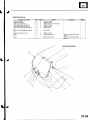
Left Side Turn Signal Light Sub harness
Connectoror Terminal
Leftsideturn signallight
c506
22-26
35
34
Cavities
Location
2
B e h i n d l e f t s i d e t u r n s i g n a ll i g h t
2
Under left side of dash
Connectsto
Dashboard
wire harnessA
Noles
WIRE
DASHBOARD
A
HARNESS
,./
-19
20
34
LEFTSIDETURN SIGNAL LIGHT
SUB HARNESS
I
2s
). \'u
)t
30
(cont'd)
22-27
Connectorsand Harnesses
Connectorto HarnessIndex (cont'd)
DashboardWire HarnessA (Rightbranch)
Connecloror Terminal
Cavities
Location
20
Eehindaudiounit
10
Underrightsideof dash
Audiounitconnector
c501
6
c502
5
4
Underrightsideof dash
c502
5
8
Underrightsideof dash
c503
4
5
tJnderrightsideof dash
c5' 11
c512
c514
ca52
c853
Undermiddleof dash
12
8
Undermiddleof dash
8
2
Underrightsideof dash
9
Underrightsideof dash
10
6
Underrightsideof dash
2
21
Undermiddleofdash
3
'l
G502
Undermiddleof dash
Underrightsideof dash
Connectsto
Enginecompartment
wire
harness(seepage22,18)
Enginecompanmentwire
harness(seepage22-18)
Enginecompartment
wire
harness(seepage22-18)
Enginecompartment
wire
harness(seepage22-18)
ECN4
wire harness(seepage
22-321
Floorwire harness{seepage
22-341
Rightsideturn signallight
suonarness
Passenger's
doorwire
harness(seepage22 4l)
Passenger's
doorwire
harness(seepage22 4'l)
A,/Cwire harness(seepage
22-43)
ly'Cwire harness(seepage
22-431
Eodygroundvia dashboard
Notes
USA
Canada
Right Side Turn Signal Light Sub harness
ConnectororTorminal
Rightsideturn signallight
c5't3
22-28
1
8
Cavities
Location
2
Eehindrightsideturn signallight
2
Underriohtsideof dash
Connectsto
Dashboard
wire harnessA
Not€s
WIBE
DASHBOARO
HARNESS
A
'---/...'
T
I
22-29
Connectors
and Harnesses
Connectorto HarnessIndex(cont'd)
DashboardWire HarnessB
Collqctor or Terminal
C a b l e reel
2
1
17
16
't9
Cavities
Locatiol|
5
In steeringcolumncover
In steeringcolumncover
4
In steeringcolumncover
In steeringcolumncover
1
In steeringcolumncover
1
In steeringcolumncover
4
Undermiddleof dash
18
Undermiddleofdash
14
In steeringcolumncover
5
Underleft sideof dash
Combination
lightswitch
Driver'sairbaginflator
lgnitionkey switch
lgnitionswitch
lmmobilizer
controlunit receiver
Passenger's
airbaginflator
SRSunitconnector
A
Wiper/washerswitch
Underdashfuse/relay
box
connectorAlseepage22,45)
Under dashluse/relaybox
connectorB (seepage22-45)
Under'dash
fuse/relay
box
connectorC (seepage22-45)
Under-dash
fuse/relay
box
connector
S lseepage22-45)
Under'dash
fuse/relay
box
connectorX(seepage22 45)
c401
10
c402
12
10
Undermiddleof dash
c403
11
4
Undermiddleof dash
G510
14
12
Undermiddlesideof dash
G40l
22-30
18
I
3
5
6
6
Underleftsideofdash
14
Underleftsideof dash
1
2
Underlettsideof dash
8
8
Under left sideof dash
Underrightsideof dash
Undergaugeassembly
Connectsto
Enginecompartment
wire
harness(seepage22-'18)
Floorwire harness(seepage
22-34J
Floorwire harness(seepage
22-341
Dashboard
wire harnessA
(seeoaoe22-26)
Bodygroundviadashboard
Notes
WIRE
OASHBOARD
HARNESS
B
22-31
Connectors
and Harnesses
Connectorto HarnessIndex(cont'd)
ECMWire Harness
Connectoror TerminiF
Arrruert/vrl ralo sensorretay
Datalinkconnector
EC[/lconnectorE
PGM-Flmainrelay1
PGM-Flmainrelay2
Under-dash
fuse/relay
box
connector
D (seepage22 45)
Underdashfuse/relay
box
connectorE lsee page22-45)
under-dashfuse/relaybox
connectorR lsee page22-45)
c10'1
I Re- lcavities
8
7
6
1
4
4
2
L
Location
Eehindglovebox
Undermiddleof dash
Behindglovebox
Behindglovebox
Behindglovebox
In the under-dash
fuse/relay
box
Inthe under-dash
fuse/relay
box
3
6
In the under-dash
fuse/relay
box
4
20
Underrlghtsideof dash
c152
1' I
8
Underrightsideof dash
c451
I
c452
10
4
Underrightsideot dash
c453
14
6
UndermiddleoI dash
c511
12
G451
22-32
Connectsto
Underrightsideof dash
Undermiddleof dash
Undergaugeassembly
Enginewire harness(see
page22'16)
EPSsubharness(seepage
22-24)
Enginecompanment
wire
harness{seepage22-18)
Enginecompartment
wire
harness{seepage22-18)
Floorwire harness(seepage
22-34)
Dashboard
wire harness
A
{seeoaoe22-26)
Bodygroundvia ECMwire
harness
Notes
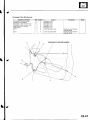
ECMWIREHARNESS
22-33
Connectorsand Harnesses
Connectorto Harnesslndex (cont'd)
FloorWire Harness(Frontsidel
Connec-tor
or Terminal
I
Driver'sseatbeltswitch
Driver'ssideairbaginflator
Driver'ssideimpactsensor
Leftside seatbelt buckletensioner
Memoryerasesignal(MES)connector
Parkingbrakeswitch
Passenger's
seatbelt switch
Passenger's
sideairbaginflator
Passenger's
sideimpactsensor
Rightsideseatbeltbuckletensioner
SRSunitconnector
B
SRSunitconnector
C
Under-dashfuse/relaybox
connector
P {seepage22-45)
Under-dash
fuse/relay
box
connectorO (seepage22,45)
c402
c403
Ref
uavftres
11
l0
13
12
19
9
5
3
7
4
20
21
11
3
2
2
4
2
1
3
2
2
4
18
8
18
'r8
8
22
23
c453
10
4
Location
I Underdriver'sseat
i Underdriver'sseat
I Leftside offloor
Underdriver'sseat
Underdashfuse/relay
box
1Middleoffloor
Underpassenger's
seat
Underpassenger's
seat
Rightsideoffloor
Underpassenger's
seat
I Undermiddleof dash
Undermiddleof dash
Underdashfuse/relay
box
Underdashfuse/relay
box
]
I
Undermiddleof dash
Undermiddleof dash
6
Undermiddleof dash
c508
2
4
Undermiddleof dash
c509
14
6
Undermiddleofdash
c512
1
8
10
6
G551
22-34
I
4
connects to
Undermiddleof dash
I
Undermiddleof dash
] Unaermiddleof aasn
L,nderpassenger's
seat
Dashboard
wire harnessB
{seepage22 30)
Dashboard
wire harnessB
(seepage22-30)
ECMwire harness(seepage
22-321
Dashboard
wire harnessA
(seepage22-26)
Dashboard
wire harnessA
\see page 22-26)
Dashboard
wire harnessA
{seepage22-26)
Enginecompartment
wire
harness(seepage22 18)
OPDSunitharness(seepage
22-421
Bodygroundviafloorwire
Nol6s
- 10
11
FLOORWIREHARNESS
( c o n t ' d)
22-35
Gonnectors
and Harnesses
a
Connectorto HarnessIndex (cont'dl
Floor Wire Harness {Rear side}(cont'dl
Cargoarea
Driver'sdoorswitch
EVAPemissionbypasssolenoidvalve
EVAPemissioncontrolcanistervent
shutvalve
Fuelpump/sending
unit
Fueltankpressure
sensor
Left back-uplight
Left rearABS wheel sensor
Leftrearsidemarkerlight
Left rear speaker
Leftrearturn signallight
Leftsideseatbelttensioner
LefttaillighVbrake
light
(rearwindow
Noisecondenser
defogger)
(rearwindowwiper)
Noisecondenser
Passenger's
door switch
Rearwindowwiperintermiftent
controlunit
Rightback-uplight
Righttaillighvbrake
tight
Rightrearturn signallight
BightrearABSwheelsensor
Rightrearsidemarkerlight
Rightrearspeaker
Rightsideseatbelttensioner
c554
6
2
24
2
1
2
2
LeftB pillar
Fueltank
Fueltank
I
3
25
1
26
4
2A
5
27
'13
5
3
2
2
2
2
2
2
3
2
Fueltank
Fueltank
Lefttaillight
Left rear offloor
Behindleftsideof rearbumper
Leftquarterpanel
Lefttaillight
LeftB-pillar
Lefttaillight
Rightquarterpanel
18
10
11
2
1
20
Rightquarterpanel
R i g hB
t pillar
Rightq uarterpanel
22
20
21
15
19
12
11
7
2
3
2
2
2
2
2
12
Righttai ight
Righttaillight
Righttaillight
Rightsideof cargoarea
Behindrightsideof rearbumper
Rightquanerpanel
RightB-pillar
Rightquanerpanel
I
12
Rightquanerpanel
side of cargo area
rearseal bdcl
Rightsideof cargoarea
22-36
H a t c hw i r e h a r n e s s( s e ep a g e
22 39)
H a t c hw i r e h a r n e s s( s e e p a g e
Bodv ground vta
Bodygroundviafloorwire
FLOORWIREHARNESS
22-37
Connectors
and Harnesses
Connectorto HarnessIndex(cont'd)
RoofWire Harnsss
Connectoror Terminal
Moonroofclose
relay
Moonrool control unit
Moonroofmotor
Moonrootopenrelay
Moonroofpositionsensor1
N4oonroofpositionsensor2
Moonroofswitch
Rearceilinglight
SpotlighVceiling
light
c507
22-38
6
I
7
8
5
1
2
10
Cavities
5
5
2
5
2
4
5
3
4
8
tocation
Middleof roof
Middleof roof
Middleof roof
Middleof roof
MiddleoI roof
Middleof roof
Frontof roof
N4iddleof roof
Frontof roof
Underleftsideof dash
Connectsto
Dashboard
wire harnessA
(seeoaoe22-261
Notes
HatchWire Harness
Connectoror Torminal
Hatchlatchswitch
Hatchlockactuator
Highmountbrakelight
Licenseplatelight connectorA
Licenseplatelight connectorB
Rearwindowde{ogger
connector
A
I
3
Cavities
2
2
2
2
2
1
B
Bearwindowdetoggerconnector
10
1
LeftC-pillar
Bearwindowwipermoto.
c553
6
2
4
12
Middleof hatch
Rightquanerpanel
c554
l
2
Rightquanerpanel
( )
7
8
Location
Middleo{ hatch
Middleof hatch
Behindhighmountbrakelight
Middleof hatch
Middleof hatch
RightC-pillar
Connects to
Notes
Floorwire harness(seepage
22-341
Floorwire harness(seepage
)2-34\
22-39
Connectors
and Harnesses
Connectorto Harnesslndex (cont'd)
\,
Driver'sDoorWire Harness
Connectoror Terminal
Driver'sdoor lockactuator
Driver'sdoorlockknobswitch
Driver'sdoor lockswitch
Driver'sdoorspeaker
Driver'spowerwindow motor
Left power mirror actuator
Left tlveeter
Powerwindow masterswitch
c504
c505
ReI
9
10
1
7
2
3
Cavities
2
3
3
2
Location
8
5
20
Driver'sdoor
Driver'sdoor
Driver'sdoor
Driver'sdooa
Driver'sdoor
Driver'sdoor
Driver'sdoor
Driver'sdoor
Underleftsideof dash
6
't3
Underleftsideof dash
6
2
DRIVER'SOOORWIREHABNESS
22-40
Connectsto
A
Dashboard
wire harness
\seepage22-261
A
Dashboard
wire harness
Notes
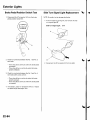
Passenger'sDoor Wire Harness
Connectoror Terminal
Passenger's
doorlockactuator
Passenger's
doorspeaker
powerwindowmotor
Passenger's
powerwindowswitch
Passenger's
Rightpowermirroractuator
Righttweeter
c514
Rel
6
I
5
1
4
3
2
Cavities
2
2
2
5
6
2
13
Passenger's
door
Passenger's
door
Passenger's
door
Passenger's
door
Passenger's
door
Passenger's
door
Underrightsideof dash
1
6
Underrightsideof dash
Location
Connectsto
Notes
Dashboard
wire harnessA
(seepage22'26)
Dashboard
wire harnessA
lsee oeoe 22-26\
PASSENGER'S
DOORWIREHABNESS
22-41
and Harnesses
Gonnectors
Connectorto Harnesslndex {cont'dl
OPDSUnit Harness
ConnoctororTorminal
OPDSunit
Cavitios
2
1
I
Location
In frontpassenger's
seat
Underfrontpassenger's
seat
FLOORWIBEHARNESS
22-42
Connectsto
Floorwareharness(seepage
22-34)
Notes
A/C Wire Harness
Connoctoror Terminal
Air mix controlmotor
Blowermotor
Evaporator
temperature
sensor
Modecontrol motor
Powertransistor
Recirculation
controlmotor
c851
Rel
I
2
8
3
4
1
1
Cavities
5
2
2
10
5
1
Undermaddle
of dash
Underrightsideof dash
Undermiddleof dash
Underrightsideof dash
Underrightsideof dash
Underrightsideof dash
Undermiddleol dash
c852
6
21
Undermiddleofdash
c853
5
,]
Undermiddleo{ dash
Location
Connec'tsto
Notes
Enginecompartment
wire
harness(seepage22-18)
Dashboard
wire harnessA
{seepage22 26i
Dashboard
wire harnessA
lsee oaoe 22-261
22-43
Fuse/Relay
Boxes
Connectorto Fuse/RelayBox Index
Under-hoodFuse/RelayBox
Socket
Ref
14
2
Ay'Ccompressorclutch relay
B
Blower motor relay
c
15
9
C o n d e n s efra n r e l a y
D
E
E L Du n i t
H e a d l i g hrte l a y1
Headlightrelay 2
Horn relay
Radiatorfan relay
Rearwindow defoqqerrelay
T1 (Batterv)
T101 (Alternator)
-
I
L'
-
1'
11
to
5
6
10
'l
J
|
||
-
-
-
T---r .-:-
t L _ _| . 1 I
t
t
t
L
"
"
tr
T
T
tTt Tr
,/^-------lFr
-/1-l
szl:!)
lrt
lview of tront sidel
22-44
Startersubharness(seeoaqe22-15)
Startersubharness{seeoaoe22-'15}
8
7
a-------) |
-
4
4
4
t t-l t t_l t tIl L l L l t l ' " . -
""""-l-
r^l
tt
Terminal
Connects to
2
Enginecompartmentwire harness(seepage 22-18)
4
5
Enginecompartmentwire harness(seepage22-18)
4
Enginecompartmentwire harness(seepage 22-18)
4
14
Enginecompartmentwire harness(seepage 22-18)
7
E n g i n ec o m p a r t m e nwt i r e h a r n e s s( s e ep a g e2 2 - 1 8 )
3
Enginecompartmentwire harness{seepage 22-18)
4
{View of back side)
Under-dashFuse/RelayBox
Socket
B
c
D
E
F
G
H
Ref
Terminal
2
3
1
5
6
14
5
19
9
I
20
13
12
10
3
J
K
24
22
27
26
7
M
N
o
P
Powerwindow relay
o
6
10
25
14
18
R
S
Startercut relay
T
Taillightrelay
Turn signal/hazardrelay
U
11
1:
.o^
;;
4
8
2
in
a
Floorwire harness(seepage 22-34)
ECMwire harness(seepage 22-32)
Dashboardwire harnessB (seepage 22-30)
Multiplexcontrol unit servicecheckconnector
l
l
17
2
Optionalconnector
Optionalconnector
Floorwire harness(seepage22-34)
28
I
13
{Plugsdirectly into the multiplexcontrol unat)
( P l u q sd i r e c t l vi n t ot h e m u l t i D l e cx o n t r o lunrl)
l5
to
W ( M e m o r ye r a s es i g n a l( M E S )
connector)
X
Y
:
11
'10
Connects to
Dashboardwire harnessB {seepage 22-30)
Dashboardwire harnessB {seepage 22-30)
Dashboardwire harnessB (seepage 22-30)
ECMwire harness(seepage 22-32)
ECI\4wire harness(seepage 22-32)
Enginecompartmentwire harness(seepage 22-'l8l
Enginecompartmentwire harness(see page 22-181
E n g i n ec o m p a r t m e nwt i r e h a r n e s s( s e ep a g e2 2 - 1 8 )
Enginecompartmentwire harness(see page 22-18)
Enginecompartmentwire harness(seepage 22-18)
Dashboardwire harnessA (seepage 22-26)
Dashboardwire harnessA (seepage 22-26)
Dashboardwire harnessA (seepage 22-26)
Dashboardwire harnessA (seepage 22-26)
Dashboardwire harnessA (seepage 22-26)
Floorwire harness(seepage 22-34)
l t
tn--rl
I U LI L.]L.J
h - - n UL]L]UL]
I] L] L] LI L]
!3
12
22-45
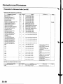
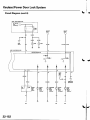
PowerDistribution
Fuseto Componentslndex
Under-hoodFuse/RelayBox
Fuse
Number
'I
Amps
204
15A
WireColor
Component(sl or Circuit(s) Protected
BLUI/EL Condenserfan motor
BLU/RED Ay'Ccompressorclutch
WHT/GRN Dashlights,Front parkinglights,Frontside marker lights,Licenseplate
l i q h t ,R e a rs i d em a r k e rl i q h t s T
, ailliqhts
15A
WHT/BLU C a r q oa r e al i q h t ,C e i l i n ql i q h t s l. q n i t i o nK e v l i q h t .S o o t l i o h t s
BLU/BLK Radiatorfan motor
WHT/BLK Turn siqnal/hazardrelav,Turn siqnal liqhts
WHT/BLK CKPsensor,ECM,IACvalve, lmmobilizercontrol unit-receiver,Injectors,
15A
WHT/GRN Brakelights,Brakesignals(to ABS modulator-controlunit, Cruisecontrol
20A
10A
B L U / R E D i1Orns
WHT/GRN ABS modulatorcontrol unit
, a u g ea s s e m b l yl,m m o b i l i z e r
WHT/RED A u d i o u n i t ,D a t al i n kc o n n e c t o(rD L C )G
7.5A
5
204
10A
P G M - Fm
I a i n r e l a v1 a n d 2 . T D Cs e n s o r
7
unit, ECM)
8
9
control unit-receiver,lmmobilizerindicatorlight. Keylessreceiverunil,
lvlultiDlexcontrol unit
10
40A
11
30A
IJ
40A
40A
14
40A
t5
15A
16
17
204
WHT/RED ABSmodulator-control
unit
BLK/YEL Noisecondenser,Rearwindow defoqqer
BLU^^/HT Blower motor
WHT/BLK No. 7 fuse (in the under-dashfuse/relavbox), Powerwindow relav
WHT/RED No.2 and No.3 fuses (in the under-dashfuse/relavbox)
REDI/EL Daytimerunning lightscontrol unit (Canada),Daytimerunning lights relay
{ C a n a d a )H, i o hb e a mi n d i c a t o lri q h t .L e f th e a d l i q h t
18
19
20
15A
60A
WHT
Multiplexcontrol unit
RED
D a v t i m er u n n i n ql i q h t sc o n t r o lu n i t ( C a n a d a )R. i o h th e a d l i o h t
WHTiBLU EPScontrol unit
80A
40A'
50A'?
WHT
Batterv.Power distribution
lgnition switch (BAT)
* 1 :U S A
" 2. Canada
l
l
II
I
E'l
22-46
t4 " t |
t
l
lI
l - - -
E,l E,l r--r r---rt__J i; i6'!/'
E,l E,l E,l
l'lr]n
r L__J,a
,..r^{-------l^-,
n[:]$"Lrt
O: Sparefuse
t
t
" N2,
Eol E l f__--l
|
|
nf
- r^l
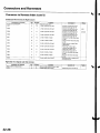
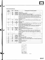
Under-dashFuse/RelayBox
Fuse
Number
Amps
1
15A
2
3
204
10A
10A
5
6
7.5A
7
204
I
7.5A
9
10A
10
7.54
11
7.5A
7.5A
12
13
't4
10A
10A
1E
Wire Color
Component(s) or Circuit(s) Protected
BLKA/VHT l g n i t i o nc o i l s
WHT/RED Airlfuelratiosensor,ECM
RED/BLU D a y t i m er u n n i n gI i g h t sc o n t r o lu n i t{ C a n a d a )
BLI(ORN Air/fuel ratio sensorrelay,Alternator,CMP sensor,Cruisecontrol main
switch,Cruisecontrol unit. ELDunit, Evaporativeemission(EVAP)bypass
solenoidvalve, Evaporativeemission(EVAP)canisterpurge valve,
Evaporativeemission(EVAP)canistervent shut valve,SecondaryH02S,
Vehiclespeed sensor
Not used
Y E U G R N Moonroof control unit, Moonroof open and close relay,Powerwindow
relaV
GRN
Moonroof motor
YEURED A u d i o u n i t
GRN
OPDSunit, Rearwindow wiper motor, Rearwindow washer motor, Rear
window wiper intermittentcontrol unit
YEL
Back-uplights,Cruiseindicatorlight, EPScontrol unit, Gaugeassembly,
Keylessreceiverunit, Multiplexcontrol unit, Securitycontrol unit
connector(optional)
BLIVORN ABS modulator-controlunit
YEURED D a y t i m er u n n i n ol i o h t sc o n t r o lu n i t ( C a n a d a )
PNK
S R Su n i t
BLK/YEL A,,/C
compressorclutch relay,Blower motor relay,Condenserfan relay,
Heatercontrol panel,Power mirror actuator,Power mirror defogger
(Canada),Radiatorfan relay,Rearwindow defoggerrelay,Recirculation
control motor
Not used
17
15A
18
19
15A
7.5A
20
21
22
23
24
25
30A
Notused
YEL/BLK E C M ,F u e lp u m p
BLK/YEL >H> Unrr
Y E U G R N Accessorypower socket
Y E U B L K T u r ns i q n a l / h a z a rrde l a v T
, u r ns i q n a l i o h t s
G R N / B L K M u l t i p l e xc o n t r o lu n i t ,W i n d s h i e l dw a s h e rm o t o r .W i n d s h i e l dw i o e r m o t o r
204
20A.
G R N / B L K Passenqer'swindow motor
GRN,A/VHT Driver'swindow motor
lo
Not used
Not used
Notused
_ _ ^ :
Hr tl_l
f at-t
at\t I
r^,rl fl
!!;r -
!f 3 3 9: , i ; s ! ! s
Fnf
|rnITf
22-47
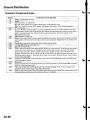
GroundDistribution
Groundto ComponentsIndex
Componentor circuit qrounded
Ground
Batterv,Transmissionhousinq
En g i n e
G1 0 1
G 15' ]
ECM(PGis BLK;LGis BRN/YEL)
BLK:IACvalve,lgnitioncoils,Vehiclespeedsensor,VTECsolenoidvalve
switch
BRNA/EL:
Camshaft
oosition(CMP)sensor.CKPsensor,TDCsensor.VTECoil pressure
EPScontrolunit
G201
ELDunit. Multiplexcontrol inspectionconnector,Multiplexcontrol unit, Powerwindow relay,Rear
window washer motor, Rightfront parkinglight, Rightfront side marker light, Rightfront turn signal
light,Turn signal/hazardrelay,Washerfluid level sensor(Canada), Windshieldwasher motor,
WindshieldwiDer motor
G202
G301
ABSmodulator-control
unit
G401
G402
G4 5 1
G501
G502
G503
G551
G552
22-48
Blower motor relay,Brakefluid level switch,Condensorfan motor, Cruisecontrol actuator,Leftfront
parkinglight, Leftfront side marker light, Leftfront turn signallight, Radiatorfan motor, Radiatorfan
swrtcn
Combinationliqht switch,lqnitlon kev srvitch,Wiper/wasfrersr,virch
Left and riqht airbaqsensors,SRS unit
Datalink connector(DLC)
Clutchinterlockswitchm Clutchpedal positionswitch (for cruisecontrol),Cruisecontrol main switch,
Cruisecontrol unit, Daytimerunning lightscontrol unit (Canada),Driver'sdoor lock knob switch,
Driver'sdoor lockswitch,Driver'spower window motor, Heatercontrol panel,Left power mirror
defogger(Canada),left side turn signal light, Moonroof control unit, Monroof open and close relays,
'1,
Moonroof positionsensor Moonroof seitch,Power mirror switch,Powertransistor,Powerwindow
masterswitch.SDotliqhts
Accessorypower socket,Gaugeassembly,Keylessreceiverunit, lvlultiplexcontrol unit, Right power
m i r r o rd e f o g g e {r C a n a d a )
A u d i ou n i t
Driver'sseat belt switch,Fuelgauge sendingunit, Fuelpump, Memory erasesignal(IMES)connector,
OPDSunit. Riohtseat belt switch
High mount brakelight, Licenseplate lights,Rearwindow defogger,Rearwindow defoggernoise
condenser.Rearwindow wioer motor, Hatchlatch switch
Back-uplights,Brakelights,Rearside marker lights,Rearturn signal lights,Rearwindow wiper noise
condenser,Rearwindow wiper intermittentcontrol unit, Taillights
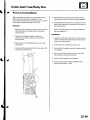
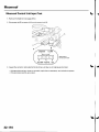
Under-dashFuse/RelayBox
Removaland Installation
SRScomponentsare locatedin this area.Reviewthe
SRScomponentlocations{seepage 23-13)and
precautionsand procedures(seepage23-14)in the SRS
sectionbeforeperformingrepairsor service.
Removal
1. Make sure you have the anti-theftcode for the radio,
then write down the frequenciesfor the radio's
presetbuttons.
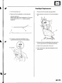
5. Removethe mounting bolt, and slidethe underdash fuse/relaybox (A) down from the bracket{B).
6. Disconnectthe backside from connectorsfrom the
back of the under-dashfuse/relaybox, and remove
the fuse/relaybox.
N O T E : T h eS R Sc o n n e c t o irs a s p r i n g - l o a d eldo c k
type (seepage 23-11).
lnstallation
2. Disconnectthebatterynegativecable,then
disconnectthe positivecable,and wait at least
three minutes.
1. Installthe under-dashfuse/relaybox in the reverse
order of removal and connectall connectorsto the
under-dashfuse/relaybox.
3. Removethe driver'sdashboardlower cover (see
page 20-59).
2 . I n s t a l l t h ed r i v e r ' sd a s h b o a r dl o w e rc o v e r .
4. Disconnectthe connectorsfrom the fuse side of the
under-dashfuse/relaybox.
3. Connectboth the negativecable and positivecable
to the battery.
4. Enterthe anti-theftcode for the radio,then enter
the customer'sradio stationpresets.
5. Confirmthat all systemswork properly,
6 . D o t h e e n g i n ec o n t r o lm o d u l e( E C M )i d l e l e a r n
p r o c e d u r e( s e ep a g e1 1 - 1 3 9 ) .
22-49
Battery
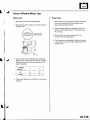
Battery Test
A batterycan explodeif you do not follow the
proper procedure,causingseriousinjury to anyone
nearby.Follow all procedurescarefullyand keep
sparksand open flames away from the battery.
Use eithera JCI or BearARBSTtester,and follow the
manufacturer'sprocedures.lf Vou don't have one of
these computerizedtesters,follow this conventional
test procedure:
1. Be sure the temperatureof the electrolyteis
between70'F (21"C)and 100'F(38'C).
2. Inspectthe batterycasefor cracksor leaks.
. l f t h e c a s ei s d a m a g e d r, e p l a c e t h eb a t t e r y . l
. lf the case looksOK, go to step 3.
3. Checkthe indicatorEYE.
. lf the EYEindicatesthebafteryischarged,goto
step 4.
. l f t h e E Y Ei n d i c a t e s al o w c h a r g e ,g o t o s t e p 7 .
4. Apply a 300 amp load for 15 secondsto removethe
surfacecharge.
5, Wait 15 seconds,then apply a test load of 280 amps
for 15 seconds.
6. Recordbatteryvoltage.
. l f v o l t a g ei s a b o v e 9 . 6 v o l t s , t h e
b a t t e r yi s O K . l
. l f v o l t a g ei s b e l o w 9 . 6 v o l t sg, o t o s t e p T .
7 . C h a r g et h e b a t t e r yo n H i g h( 4 0a m p s )u n t i lt h e E Y E
shows the batteryis charged,plus an additional30
minutes.lf the batterychargeis very low, it may be
necessaryto bypassthe charger'spolarity
protectioncircuitry.
. l f t h e E Y Ei n d i c a t e s t h eb a t t e r yi s c h a r g e d w i t h i n
3 hours,the batteryis OK.l
. lf the EYEindicatesthebatteryis notcharged
within 3 hours,replacethe battery.l
22-50
{
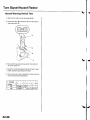
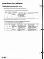
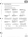
Relays
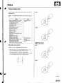
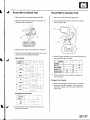
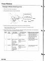
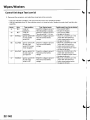
PowerRelayTest
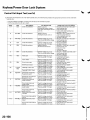
Usethischanto identifythetypeof relay,thendo the
testlistedfor it.
type 1:
NOTE:Turnsignal/hazard
relayinputtest(seepage2287).
Relay
A'lCcomoressor
clutchrelav
Airlfuel ratio sensorrelav
Condenserfan relay
H e a d l i o hrte l a v1
H e a d l i q hrte l a v2
H o r nr e l a v
Powerwindow relay
R a d i a t oIra n r e l a y
Reverserelav
Startercut relav
T a i l l i q h rt e l a V
D a y t i m er u n n i n gl i g h t sr e l a y
{ C a n a d)a
Test
Normally-open
type A
type 2:
P G M - FmI a i nr e l a v1
P G M - Fm
l a i n r e l a v2
Blower motor relav
Rearwindow defoqoerrelav
Moonroofclose relay
Moonroof oDenrelav
Low beam cut relav {Canada)
Normally-open
tvpe B
F i v et e r m i n a l
type
Normally-open
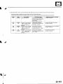
type A:
PGM-FImain relay 1
PGM-FImain relay 2
type 1:
Checkfor continuitvbetweenthe terminals.
. Thereshould be continuitybetweenthe No. 1 and
N o , 2 t e r m i n a l sw h e n p o w e ra n d g r o u n da r e
connectedto the No. 3 and No. 4 terminals.
. Thereshould be no continuitybetweenthe No. 1 and
N o . 2 t e r m i n a l sw h e n p o w e ri s d i s c o n n e c t e d .
type 2:
(cont'd)
22-51
Relays
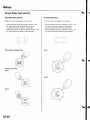
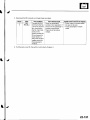
PowerRelayTest (confdl
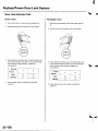
Normally-open
type B:
Five-terminal
type
Checkfor continuitybetweenthe terminals.
C h e c kf o r c o n t i n u i t yb e t w e e nt h e t e r m i n a l s .
. Thereshould be continuitybetweenthe No. 1 and
N o . 3 t e r m i n a l sw h e n p o w e ra n d g r o u n da r e
connected
t o t h e N o .2 a n d N o . 4 t e r m i n a l s .
' Thereshould be no continuitybetweenthe No, 'l and
No. 3 terminalswhen power is disconnected.
. T h e r es h o u l db e c o n t i n u i t yb e t w e e nt h e N o . 1 a n d
N o . 2 t e r m i n a l sw h e n p o w e ra n d g r o u n da r e
c o n n e c t e tdo t h e N o . 3 a n d N o . 5 t e r m i n a l s .
. T h e r es h o u l db e c o n t i n u i t yb e t w e e nt h e N o . 1 a n d
N o . 4 t e r m i n a l sw h e n p o w e ri s d i s c o n n e c t e d .
tF-gr
tJ 1l
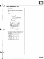
Rearwindow defonn* *O,
type 1:
6:)
rc*V
.r{{
(n F, t )\
\
s3.
Blower motor relay
type 1:
type2:
type 2;
22-52
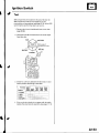
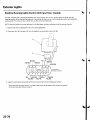
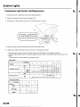
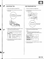
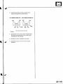
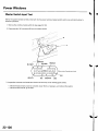
lgnitionSwitch
Test
SRScomponentsare locatedin this area.Reviewthe
S R Sc o m p o n e n lto c a t i o n s( s e ep a g e2 3 - 1 3 a
) nd
precautionsand procedures{seepage 23-'l4)in the SRS
sectionbefore performingrepairsor service.
1, Removethe driver's dashboardlower cover {see
page 20-59).
2. Disconnectthe 5P connectorfrom the under-dash
fuse/relaybox.
WHT/RED
Wiresideof
f e m a l tee r m i n a l s
BLK/YEL
BLK/WHT
BLK/RED
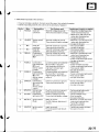
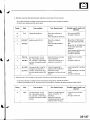
Checkfor continuitybetweenthe terminalsin each
switch positionaccordingto the table.
\
Terminal WHT/
BLK/ BLK/ BLK/
RED WHT YEL RED WHT
p.J,i""-\ (ACC)
(BAT) flGl) trc2t (sr)
o (LocK)
| (ACC)
o- --o
_H
[ (oN)
c)III (START)
o _H
lf the continuitychecksdo not agreewith the table,
replacethe steeringlock assembly(seepage'17-121.
22-53
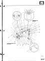
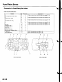
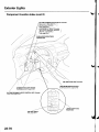
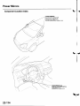
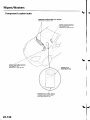
Gauges
\-
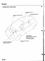
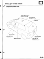
ComponentLocationIndex
PARKINGBRAKESWITCH
p a g e1 9 - 1 0
FUELGAUGESENDING
p a g e1 1 - 1 5 6
SWITCH
ENGINEOILPRESSURE
page8-4
GAUGEASSEMBLY
Procedure,page22-56
SelJ-diaqnostic
page22 63
Gauqedulb Replacement,
Rep6cement,page22-64
CoolantTemperatureGauge
page22'64
TroLrbleshooting,
VEHICLESPEEDSENSOR{VSS)
page22-65
Troubleshooting,
Beplacement,page22-67
BRAKEFLUIDLEVELSWITCH
p a g e1 9 - 1 0
\
22-54
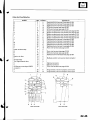
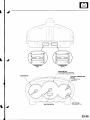
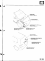
CONNECTOR
B
lgreenJ
CONNECTORA
(bluel
SPEEDOMETER
VehicleSpeedSignalCircuit
page22-65
Troubleshooting,
TACHOMETEB
\7
t----/
\
_ / \
i . . _ ODO/TRIPMETER
FUELGAUGE
Test,page11-156
22-55
Gauges
v
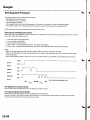
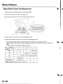
Self-diagnosticProcedure
The gaugeassemblyhas a self-diagnosisfunction.
. T h e B e e p e rD r i v eC i r c u i C
t heck
. The IndicatorDrive CircuitChecL
. The LCDSegmentsCheck
. The GaugesDrive CircuitCheck(Speedometer,Tachometer,Fuelgauge,Coolanttemperaturegauge)
. T h e C o m m u n i c a t i oLni n eC h e c k( t h ec o o l a n t t e m p e r a t u rsei g n a l i n e b e t w e e nt h e g a u g ea n d E C M )
NOTE:Indicatorsare also controlledvia the communicationline.
Enteringthe self-diagnosis
f unction:
Beforedoing the self-diagnosisfunction,checkthe No. 9 (10A)fuse in the under-hoodfuse/relaybox and No. 10 {7.5A)
fuse in the under'dashfuse/relaybox.
1. Pushand hold the trip/resetbutton.
2 . T u r nt h e l i g h t i n gs w i t c hO N .
3 . T u r nt h e i g n i t i o ns w i t c hO N ( l l ) .
4 . W i t h i n5 s e c . ,t u r n t h e l i g h t i n gs w i t c hO F F ,t h e n O N a n d O F Fa g a i n .
5. Within 5 sec.,releasethe trip/resetbutton,then push and releasethe buttonfour times reDeatedlv.
NOTE:
. While in the self-diagnosismode, the dash lights brightnesscontrolleroperatesnormally.
'Whileintheself-diagnosismode,thetrip/resetbuttonisusedtostartthebeeperdrivecircuitcheckandthegauge
drive cicuit check.
. lf the vehiclespeedexceeds1.2 mph 12km/h)orthe ignition switch is tu rned OFF,the self,diagnosis mode ends.
oN flrl
lgnition
OFF
Switch
Lighting
Switch
Trip/Reset
Switch
->
5 sec.
Move to selt-diagnosis mode.
5 sec.
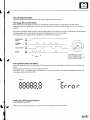
The BeeperDriveCircuitCheck:
When enteringthe self-diagnosismode, the beepersoundsfive times
TheIndicatorDriveCircuitCheck:
When enteringthe self-diagnosismode,the following indicatorsblink.
Seatbelt indicator,Door/hatchindicator,Brakesystem,Lowfuel indicator,Maintenancerequiredindicator(USA),
) , i l p r e s s u r el i g h t .
W a s h e rf l u i d l e v e li n d i c a t o (r C a n a d a O
22-56
\
The LCDSegmentCheck:
W h e ne n t e r i n gt h e s e l f - d i a g n o s m
i s o d e ,t h e o d o / t r i ps e g m e n tb l i n k sf i v et i m e s .
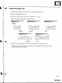
TheGaugeDriveCircuitCheck:
W h e ne n t e r i n gt h e s e l f - d i a g n o s m
i s o d e ,t h e s p e e d o m e t e trh, e t a c h o m e t e rt ,h e f u e l g a u g e ,a n d t h e c o o l a n t
g a u g en e e d l e ss w e e pf r o m t h e m i n i m u mp o s i t i o nt o m a x i m u mp o s i t i o nt,h e n r e t u r nt o t h e m i n i m u m
temperature
posrtron.
NOTE:After the beeperstops soundingand the needlesreturnto the minimum position,pushingthe trip/resetbutton
s t a r t st h e b e e p e rd r i v ec i r c u i tc h e c k( o n eb e e p )a n d t h e g a u g ed r i v ec i r c u i tc h e c ka g a i n .
T h e c h e c kc a n n o tb e s t a r t e du n t i l t h en e e d l e sr e t u r nt o t h e m i n i m u mp o s i t i o n .
Self-diagnosis
mode
ON
OFF
Trip/Reset
switch
9loFF _---
causeneedlesXl"
Beeper
ON
;;
r
n =--llJL--
f---U---------l
r-r r-r r-r .-1 r-r
r-r
lll u u l_lL__l
I
@,
[-----l
l-l
The needlessweepfrom the
minimum positionto the
maximum position,then return
t o t h e m i n i m u mp o s i t i o n -
5 sec
The Communication Line Check:
In the self-diagnosismode, after the odo/trip LCDsegmentscheck,the self-diagnosisstartsthe communicationline
cnecK.
l f a l l s e g m e n t sc o m e so n , t h e c o m m u n i c a t i o lni n e i s O K .
" E r r o r "i s i n d i c a t e d ,
l f t h ew o r d
t h e r ei s a m a l f u n c t i o ni n t h e c o m m u n i c a t i o lni n e b e t w e e nt h e g a u g ea s s e m b l yt.h e
m u l t i D l e cx o n t r o lu n i t .a n d t h e E C M .
Faulty:
Normal:
iD
:-l!:!!JlJ!J
t l
i-
f l
O i -
,-
t
--
-
,-
r-
i-
,
| | | t t f
i-
r-
Endingthe self-diagnosisfunction:
T u r nt h e i g n i t i o ns w i t c hO F F .
N O T E lrf t h e v e h i c l es p e e de x c e e d s1 . 2m p h { 2 k m / h ) t, h e s e l f d i a g n o s i sf u n c t i o ne n d s .
22-57
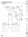
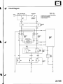
Gauges
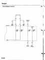
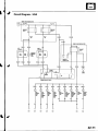
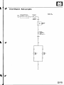
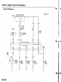
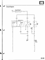
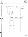
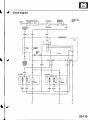
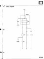
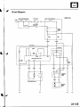
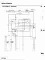
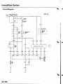
CircuitDiagram
'
UflOEN fiOOOFUSE/8ILAY
8OX
ECM/PCM
V
I
-r'
r--l
l J ,
I
I 8|
COOLANI
TEMPfNAIUFT
SPIEDOMEIENTACHOMEIIR FUTLGAUGI GAUGE
Norll0AlFUSE
8L(
-o-
22-58
ii-ciorurnn
coNNECron
N o 2 0 i o A: lU S A
ti) l To mxr I
MAi{IIiIANCE
ft0unlD
[{0tcaTo8
LIGH]
(LEDI
(cont'd)
22-59
Gauges
I
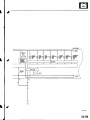
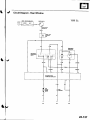
CircuitDiagram(cont'dl
No2il5AlFUSE
ilnlh.undi hooq
llu!./rcl.ybox r
DASH
LGHTS
Yt
Yl
t
'-
l
-t
WASHEF
Itut0
I!VEL
6t0tc ToR
UGHT
(tDl
J
ls?2
I
BLUIYEL
I
J
cSutsE
m n0L
a
22-60
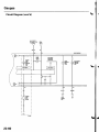
'-
./
ib-n'rnoL
UNIT
tNGniEorL
PRESSUBE
swtTcH
lCld.d Eisin.3topp.d
l
iopd Ersin.runni.s
i
I
!
i
I
I
L
--t
DAYTIME
BUNN|NG
LIGHTS
@NTROL
UNII
I
;
I
-.-..
I
i
icmadd
(cont'd)
22-61
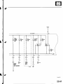
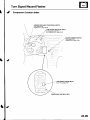
Gauges
CircuitDiagram(cont'dl
\"
GRNIfiED
I
\""'7
V
GAUGIASSEi|BLY
LEFTTUN
SIGI'IAL
II'{DICATOR
LTCHTS
HIGHSEAM
-|.
IMMOBITIZER
ltDtcATon r/: \ tilucaToB
f,il
CoME|NAT|ON
LtctlTswtTclt
vll9i,]
\,
tMf,tOBtUZEn
@l\tTRoL
UN|I ftCtIVER
J
22-62
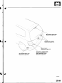
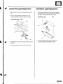
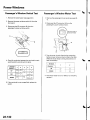
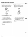
GaugeBulb Replacement
LIGHT{1.4WI
RIGHTTURNSIGNALINDICATOR
CRUISE
HIGHBEAMINOICATOR
LIGHT{1.4W)
ITORLIGHT{I.4W)
LEFTTURNSIGNALINDICATORLIGHTl1.il wl
GAUG€LIGHT{1.4WI
GAUGELIGHT{1.4W}
IMMOBILIZENINDICATOR
LTGHT
{1.4Wl
22-63
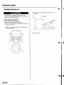
Gauges
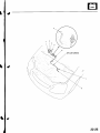
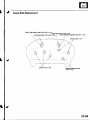
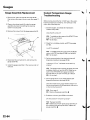
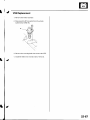
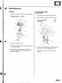
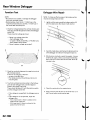
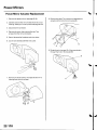
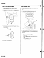
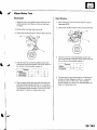
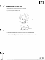
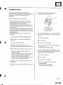
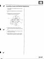
GaugeAssemblyReplacement
CoolantTemperature
Gauge
Troubleshooting
1 . Removethe instrumentpanel (seepage 20-59),
t h e n r e m o v et h e u p p e rc o l u m nc o v e r{ s e ep a g e1 7 -
2. P l a c ea c l e a ns h o pt o w e l ( A )u n d e rt h e g a u g e
assemblyto preventscratchingthe steering
c o l u mn o r d a s hp a n e l .
Beforetesting,checkthe No. I { 10A)fuse in the underhood fuse/relaybox and the No. '10(7.5A)fuse in the
under dash fuse/relaybox.
1. Startthe engine,and checkthe malfunction
i n d i c a t o lra m p ( M l L ) .
3 . Removethe screwsfrom the gauge assembly(B).
Does the MIL come on?
YES- Troubleshootthe causeof the ECM DTC(see
p a g e11 - 5 7 )a, n d r e c h e c k .
NO-Go to step 2.
2. Checkfor a multiplexcontrol unit DTC(seepage
22,168).
ls a DTC indicated?
YES Troubleshootingthe causeof the multiplex
control unit DTC{seepage 22-168),and recheck.
NO Go to step 3.
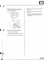
4. Disconnectthe connectors(C),and removethe
g a u g ea s s e m D r y .
I n s t a l l t h eg a u g ea s s e m b l yi n t h e r e v e r s eo r d e ro f
removal.
3 . D o t h e c o m m u n i c a t i o lni n ec h e c kw i t h t h e s e l f diagnosisprocedure(seepage 22-56).
ls the word "Error" indicated on the odo/ttip
d isplay ?
YES The gaugecannot receivethe signalfrom the
multiplexcontrol unit and the ECI\,4.
Checkfor an
open in the WHT/GRNwire (gaugeconnector
t e r m i n a lB1 3 ) .l f n o o p e ni s f o u n d ,g o t o s t e p5 .
NO Go to step 4.
4. Do the gaugedrive circuitcheckwith the selfd i a g n o s i sp r o c e d u r e( s e ep a g e2 2 - 5 6 ) .
Does the temperaturegauge needle sweep lrom
the minimum position to the maximum, then tetutn
to the minimumposition?
YES Go to step 5.
NO Replace
t h e g a u g ea s s e m b l y . l
5. Substitutea known-goodECM and recheck.
Did the symptom/ ind ication go away?
YES Replace
theECM.
NO Substitutea known good gaugeassembly.lf
the symptom/indicationgoes away, replacethe
g a u g ea s s e m b l y . l
22-64
I
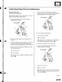
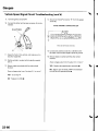
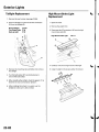
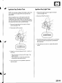
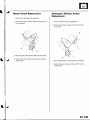
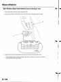
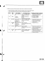
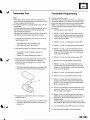
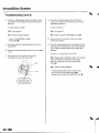
VehicleSpeedSignalCircuitTroubleshooting
Special Tools Required:
Test Harness07LAJ-PT3020A
5. Connectthe WHT test harnesscliD(B)to the
positiveprobe of a voltmeter,and connectthe RED
test harnessclip (C)to the negativeprobe.
Beforetesting,inspectthe No. 4 (10A)and No. 10 (7.5A)
fuses in the under-dashfuse/relaybox.
1. Disconnectthe 3P connectorfrom the vehicle
speedsensor(VSS){A).
T u r nt h e i g n i t i o ns w i t c hO N ( l l ) .
le thara
h2ltarv
v^ltada?
Y E S - G o t o s t e p7 .
Connectthe test harnessonly to the enginewire
harness.
wire betweenthe
NO Repairopen in the BLK,/YEL
VSS and the under-dashfuse/relaybox.l
3 . Connectthe REDtest harnessclip (B)to the positive
probe of an ohmmeter.Coverthe white (C)and
green {D)test harnessleadswith protectivetape (E).
4 . Checkfor continuitybetweenthe REDtest harness
c l i p a n d b o d yg r o u n d ,
7 . Disconnectthe WHT test harnessclip (B).
8 . C o n n e ctth e G R Nt e s th a r n e s sc l i p{ D )t o t h e
positiveprobe of a voltmeter.
ls there continuity?
YES Go to step 5.
N O R e p a i ro p e ni n t h e B L Kw i r e b e t w e e nt h e V S S
a n dG1 0 1 . I
Is there 5 V or more?
YES- Go to step 9.
NO Repairshort or open in the BLUMHT or WHT/
GRNwire betweenthe VSS and the cruisecontrol
u n i t ,o r t h e E C M . I
(cont'd)
22-65
Gauges
VehicleSpeedSignalCircuitTroubleshooting(cont'dl
9 . Turn the ignitionswitch OFF.
14. Disconnectthe 22Pconnector"8" from the gauge
assemDry.
1 0 .Connectthe other test harnessconnector(A)to the
V S S( B ) ,
GAUGE
ASSEMBLY
CONNECTOR
B (22P)
Wire side ot femaleterminals
'15.
Connectthe positiveprobe of a voltmeterto the
BLU/WHTwire and the negativeprobeto ground.
1 1 .R aisethe front of the vehicle,and make sure it is
securelysupported.
' t 2 .Put
t5.
'16.
Slowly rotateone wheel with the other wheel
blocked.
the vehiclein neutralwith the ignitionswitch
o N { |)| ,
Does voltage pulse f rom 0 to about 5 V or more?
Slowly rotateone wheel with the other wheel
blocked.
YES- Replacethe speedometerassembly.I
Does voltage pulse ttom 0 to about 5 V ot morc?
YES Go to step 14.
NO Replacethe VSS.I
22-66
NO Repairopen in the BLUMHTwiTe between
the VSS and the speedometer.l
I
J
VSS Replacement
1. Removethe intakeresonator.
2. Disconnectthe 3P connectorfrom the vehicle
speed sensor{VSS)(A).
Removethe mounting bolt, then removethe VSS.
4 . lnstallthe VSS in the reverseorder of removal.
22-67
ExteriorLights
GomponentLocationIndex
UNDER.HOOD
FUSE/RELAY
BOX
HEADLIGHT
RELAY1
Test,page22-51
HEADLIGHT
RELAY2
Test,page22-5'l
BRAKEPEDALPOSITION
swtTcH
Test,page22-84
Adjustment,page l9'6
0/
SIDETURN SIGNAL LIGHT
page22-84
Replacement,
\
/
FRONTTURNSIGNAL
LIGHT
, g e2 2 8 1
B u l bB e p l a c e m e npt a
HEADLIGHTS
page22 79
Replacement,
Adjustment.page22-78
page22-81
Eulb Replacement,
22-68
PARKINGLIGHT
B u l bR e p l a c e m e npt a, g e2 2 - 8 1
FRONTSIDEMARKERLIGHT
Bulb Replacement,page22 83
-a-.,_
z
HIGHMOUNTBRAKELIGHT
page22-82
Replacement,
LICENSE
PLATELIGHTS
page22-83
Replacement,
BACK.UPLIGHT
page22-82
Replacement,
REARSIDEMARKERLIGHT
page22-83
Replacement,
TAILLIGHTSsnd BRAKELIGHTS
page22-82
Replacement,
REARTURNSIGNALLIGHT
Beplacement,page22-82
(cont'd)
22-69
ExteriorLights
!
ComponentLocationIndex(cont'dl
DAYTIMERUNNINGLIGHTSRELAY{Canadal
[Wirecolors:RED,REDryEL,
I
andRED/BLU I
LRED/BLK
Test,page22-51
BEAMCUTRELAY
{Canadal_
_LOW
WirecolorsrREDMHT,
RED/BLK,I
andRED/BLU
I
LREDryEL
Test,page22-51
DASH LIGHTSBRIGHTNESS
CONTROLLER
. . i
'
:'
\
--,': -
' i,-'-'l
/
DRLINDICATOR
LIGHT{Canadal
HIGH BEAM INDICATORLIGHT
page22-63
Bulb Replacement,
COMBINATION
LIGHTSWITCH
page22-80
TesVReplacement,
oAYTIME RUNNING LIGHTSCONTROLUNIT lcanada)
InputTest,page22-76
I
t-
-
FUSE/
UNDER.DASH
RELAYBOX
22-70
LET]
FBOIII
SIDE
MAiKEE
L.IGHT
f,IGHT
TSONT
s]0E
MANXtF
IJGIIT
IETT
NEANSIDE
MAircN
IIGHT
I ucEr\6E
I PI.ATE
|fiIli
I
8L.l(
_o
22-71
ExteriorLights
CircuitDiagram- Canada
t
J
t
J
UNOEN
HOOO
FUSE/8ELAY
BOX
N ol 9 l 8 0 A l
J
) to.o
- i50Al
No.1'l
loa)
WHT ED
IT
N o . ! 0S( 7A lusE
r
d.3hl
V
RED,I
I- _ l
'2
/', t-\
\ rc|'/moN
. rcz/ swfrcH
I EAr
\
,'orrro"
-.
vG2Horin0N{ll)
) INDICAIOF
-/ l'lcli;
*01
I
I
I
BU1
BED
'l'I
I
I
=
.|
DNL
A
\y
II
TIGHT
luDl
RED/
BLU
,
12
l
t1
{ r-
oorr,",rr.,ro
uctrrscournoLu,'r"
J
l
I I
8
SLU/BID
3
!3
||MoS|UZEn
CONTNOL
UNIT RECEIVEB
SYSIIMUGHI
VY
I
t0
,{
--t
RE
ll
T
GNfl/FEO
DAYTIME
BUNNINC
LIGHTS
EfLAY
II
tU
HT/BI
In
RE
fifili{*1l,.H'
I
) No12
i l7.5Al
BI(
BI
BI
G8N
17
Y
I
GRI\/NED
II
I
f'
r\
(
88A(E
I FiUrD
2 , LTVEL
[./ SWITCH
F\ PANKNG
; } BNAXE
+./ swrTcH
'nddoM
I
I
i
i
G301
cl.1
G501
\,
22-72
J
J
DASH
LIGHTS
COMEINATION
LIGHT
SWIqI
TTFT
TRONT
3r0E
MABKER
LIG}IT
LEFT
PAfiX*'IG
LIG}IT
BLI(
!
t
BL](
l
G301
!
I
l
G301
BIGHT
PANKNG
LIGIIT
FIGIIT
FBONT
SIDE
MAfircF
LJGHT
l5w)
LEFT
TAIILGl T
LEFT
BEAFSIDE
LJGHT
RIGHT
RIAFSIDI
I/IAFrc8
UCHT
NEHI
I LICENSE
IAILUOHI I PLAII
I LIGNTS
(twr2l
|
8LI
I
I
G552
I
22-73
ExteriorLights
CircuitDiagram- BrakeLights
UiDENHOOD
FUSE/NEUYBOX
SATIISY
\
22-74
r!o7l15A)
I
|
,r-T-v--rrni'citr
\
CircuitDiagram- Back-upLights
UiDEN H@DFUSI/8EIAY
80)(
22-75
ExteriorLights
DaytimeRunningLightsControlUnit InputTest- Canada
T h e D R Li n d i c a t o lri g h ti n t h e g a u g ea s s e m b l yw i l l c o m e o n w h e n y o u t u r n t h e i g n i t i o ns w i t c ht o O N ( l l )w i t h t h e
headlightswitch off and the parkingbrakese1.lt should go off when you turn on the headlightswitch and releasethe
parkingbrake.lf it comes on at any other time, do the control unit input test.
r i l l g l o w a t h a l fi t s n o r m a li n t e n s i t y .
N O T EW
: h e nt h e d a y t i m er u n n i n gl i g h t sa r e o n ,t h e h i g h b e a mi n d i c a t ow
1. Removethe driver'sdashboardlower cover (seepage 20-60).
2 , D i s c o n n e c t t hle4 P c o n n e c t o r ( Af)r o m t h e d a y t i m er u n n i n gl i g h t s c o n t r oul n i t ( B ) .
RED/BLU
RED/BLU
GRN/BLK
GNN/BLK
GRN/ORN
BLU/RED
RED/YEL
YEL/RED
Inspectthe connectorand socketterminalsto be sure they are all makinggood contact.
. lf the terminalsare bent,loose orcorroded, repairthem as necessary,and recheckthesystem.
' lf the terminalslook OK, go to step 4.
22-76
\
4. Makethese input tests at the connector,
.lfanytestindicatesaproblem,findandcorrectthecause,thenrecheckthesystem.
. lf all the input tests prove OK,the control unit must be faulty. Replaceit.
2
Wire
Test condition
RED/BLU U n d e a
r ll
conditions
12
YEL/RED
Cavity
lgnitionswitch
o N( r )
BLK
7
10
U n d e ra l l
conditions
BLK
U n d e ra l l
conditions
REDI/EL C o m b i n a t i o n
light switch ON
/ =f\\
1
'11
3
5
6
8
RED/BLU
Combination
light switch ON
{iD), and
dimmer switch
inHIGH
RED/BLK C o m b i n a t i o n
light switch ON
(iD), and
dimmer switch
inHIGH
G R N / B L K C o mb i n a t i o n
light switch ON
(iD), and
dimmer switch
inHIGH
G R N / O R NParkingbrake
l e v e ro u l l e d
B L U / R E DC o m b i n a t i o n
l i g h ts w i t c hO F F
WHT/BLU lgnitionswitch
o N0 r )
t5
GR N / R E D lgnition switch
o N( | | )
Test:Desiredresult
Possiblecauseif resultis not obtained
Blown No. 14 (40A)fuse in the
under-hoodfuse/relaybox
B l o w nN o . 3 { 1 0 A ) f u s ei n t h e
under-dashfuse/relaybox
A n o p e ni n t h e w i r e
Checkfor voltageto ground:
B l o w nN o . l 2 ( 7 . 5 A ) f u s ei n t h e
Thereshould be batteryvoltage.
under-dashfuse/relaybox
An open in the wire
C h e c kf o r c o n t i n u i t yt o g r o u n d : . P o o rg r o u n d{ G 5 0 ' 1 )
. An oDenin the wire
T h e r es h o u l db e c o n t i n u i t v .
. P o o rg r o u n d( G 5 0 1 )
Checkfor continuityto ground:
' A n o p e ni n t h e w i r e
Thereshould be continuitv.
Checkfor voltageto ground:
B l o w nN o . 1 5 ( 1 5 A )f u s ei n t h e
Thereshould be batteryvoltage.
under-hoodfuse/relaybox
Faultyheadlightrelay 2
Faultycombinationlight switch
An open in the wire
Connecta jumper wire between
B l o w nb u l b
No.3 andNo.1terminals.
Faultylow beam cut relay
B o t hh e a d l i g h t (sH I G H a) n d
Faultycombinationlight switch
h i g h b e a mi n d i c a t o lri g h t
Poor ground (G50'l)
s h o u l dc o m eo n .
An open in the wire
Connecta jumper wire between . B l o w nb u l b
. Faultycombinationlight switch
N o . 5 a n d N o . 1 1t e r m i n a l s .
.
(
H
I
G
H
)
R i g h th e a d l i g h t
should
Poor ground (G50'1)
. A n o p e ni n t h e w i r e
c o m eo n .
Checkfor voltageto ground:
Thereshould be batteryvoltage.
C h e c kf o r c o n t i n u l t yt o g r o u n d
T h e r es h o u l db e c o n t i n u i t y .
. Faultycombinationlight switch
. P o o rg r o un d { G 5 0 1 )
. A n o p e ni n t h e w i r e
C h e c kf o r c o n t i n u i t yt o g r o u n d :
There should be continuitv.
Checkfor voltageto ground:
Thereshould be batteryvoltage.
Faultyparkingbrakeswitch
A n o p e ni n t h e w i r e
F a u l t yh e a d l i g hrt e l a y s
Short to ground
A n o o e ni n t h e w i r e
. B l o w nN o . 1 0 ( 7 . 5 A f)u s e i n t h e
under-dashfuse/relaybox
. FaultyDRLindicator
. A n o o e ni n t h e w i r e
Faultybrakesystem indicator
A n o p e ni n t h e w i r e
Attachto ground:
T h e D R Li n d i c a t o lri g h ts h o u l d
c o m eo n .
Attachto ground:
T h e b r a k es y s t e ml i g h ts h o u l d
c o m eo n .
22-77
ExteriorLights
\
HeadlightAdjustment
2. Parkthe vehicle7.5 m (25 ft) away from a wall or a
screen(A).
Headlightsbecomevery hot during use;do not
touch them or any attachinghardwareimmediately
afterthey have beenturned off.
7.5m {25ftl
Beforeadiustingthe headlights:
. Parkthevehicleon a levelsurface.
. Makesurethetire pressures
arecorrect.
. Thedriveror someonewho weighsthe sameshould
sit in the driver'sseat.
'1.
Cleanthe outer lens so that you can seethe center
of the headlights(A).
3 . O p e nt h e h o o d .
22-78
HeadlightReplacement
5
T u r nt h e l o w b e a m so n .
'1.
Determineifthe headlightsare aimed properly.
2 . Disconnectthe connectors(A)from the headlight
(B).
Removethe front bumper (seepage 20-85).
Verticaladjustment:
Measurethe height ofthe headlights(A).The lights
should reflect52 mm (2.'1in.) below headljght
h e i g h t( B ) .
i
6. lf necessary,adjustthe headlightsto local
requirementsby turning the verticaladjuster.
Removethe five mounting bolts,then removethe
corner upper beam (C)and headlightassembly.
Installin the reverseorder of removal.
5 . After replacement,adjustthe headlightsto local
requirements.
22-79
ExteriorLights
CombinationLight Switch Test/Replacement
1. Removethe driver's dashboardlower cover (seepage 20-60).
2. Removethe steeringcolumn covers(seepage 17-9).
3 , D i s c o n n e c t t hle6 P c o n n e c t o r ( Af)r o m t h e c o m b i n a t i o nl i g h ts w i t c h( B ) .
4 . Removethe tlvo screws,then slide out the combinationlight switch.
5 . Inspectthe connectorterminalsto be surethey are all makinggood contact.
. lf the terminalsare bent, looseor corroded,repair them as necessary, a nd recheckthe system.
.lftheterminalslookOK,checkforcontinuitybetweentheterminalsineachswitchpositionaccordingtothe
tables.
- lf the continuityis not as specified,replacethe switch.
Light switch:
\
Telmint
12
5
4
Position
OFF
Headlight switch
o--
LOW
Passingswitch
HIGH
OFF
o--
ON
o-
Turn signalswitch:
Terminal
\
2
10
Position
LEFT
----o
NEUTRAL
RIGHT
22-80
o--
11
13
Bulb Replacement
Headlight:
FrontTurn SignalLight:
ParkingLight:
1. Disconnectthe 3P connector(A)from the headlight.
1 . R e m o v et h e i n n e rf e n d e r( s e ep a g e2 0 - 1 0 2 ) .
Headlight{high/low): 60/55 W
2. Disconnecttheconnectors(A) from the lights.
Frontturn signallight:
Parkinglight:
21W
5W
f-rI
A-
-'-+l
)/
2. Removethe rubbercover (B).
Pullthe retainingspring (C)away from the bulb (D),
then removethe bulb.
Installa new bulb in the reverseorder of removal.
Make sure the notchesin the bulb align with the
t a b sl n t h e h e a d l i g h t .
Turn the bulb sockets(B) 45'counterclockwiseto
removethem from the headlighthousing.
4 . Installthe new bulb(s)in the reverseorder of
removat.
22-81
ExteriorLights
TaillightReplacement
HighMount BrakeLight
Replacement
1 . Removethe rearbumper(seepage20-86).
2 . Openthetailgate,anddisconnect
the connectors
1. Open the hatch.
(A)fromthetaillight(B).
2. Removethe plastictrim.
Brako/Taillight; 2115W
TurnSignalLight: 21 W
Back-upLight:
21W
3. Disconnectthe2P connectors(A)from the high
m o u n tb r a k el i g h t( B ) .
High Mounl BrakeLight:
5W x 5
=\\
ili--- _\
\
, \ .
r B ---'a
t
\r
\
Removethe mounting nuts and bolts,then remove
t h et a i l l i g h t .
Carefullyremovethe high mount brakelight.
5 . lnstallthe light in the reverseorder of removal.
Turn the bulb socket45' counterclockwise
to
removethe bulb socket.
When installingthe taillight.checkthe gasket;if it is
distortedor stayscompressed,replaceit.
After installingthe taillight.run water over the
taillightto make sure it does not leak.
'
22-82
LicensePlateLight Replacement
1 . Removethe hatch lower trim panel (seepage20-
P u l l t h el i c e n s ep l a l el i g h ta s s e m b l yo u t . a n d
disconnectthe 2P connector(A) from the light.
Side Marker Light Replacement
1. Carefullyprythe light(A)outofthe rearbumper,
(B)fromthe light.
anddisconnect
the 2Pconnector
Becarefulnotto damagethe rearbumper.
Side Marker Light:
5W
LicensePlateLight: 5Wx2
'[-J^
,^f , t lo \
+tiP'-
' f l ^
t
\-J
"/
\==-^
3 . S e p a r a t et h e l e n s( B )a n d h o u s i n g( C ) ,t h e n r e m o v e
2 . Removethe bulbsocket(A)by turningit 45'
counterclockwise.
thenreolace
the bulb.
the bulb.
4 . l n s t a l l t h el i g h ti n t h e r e v e r s eo r d e ro f r e m o v a l .
22-83
ExteriorLights
BrakePedalPositionSwitch Test
1. Disconnectthe4P connector(A) from the brake
pedal positionswitch {B).
SideTurn SignalLight Replacement
NOTE:Be careful nol to damagethe fender.
1 . P u s ht h e r e t a i n i n gs p r i n g( A ) .a n d r e m o v et h e s i d e
t u r n s i g n a l i g h t( B ) ,
Side Turn Signal Light:
5W
Checkfor continuitybetweenthe No. 1 and No. 2
termtnals.
. T h e r es h o u l db e c o n t i n u i t yw h e n t h e b r a k ep e d a l
rs presseo.
. Thereshould be no continuitywhen the brake
pedal is released.
Checkfor continuitybetweenthe No. 3 and No. 4
terminals{with cruisecontrol).
T h e r es h o u l db e n o c o n t i n u i t yw h e n t h e b r a k e
pedal is pressed.
T h e r es h o u l db e c o n t i n u i t yw h e n t h e b r a k ep e d a l
is released.
lf necessary,adjustor replacethe switch,or adjust
t h e p e d a lh e i g h t( s e ep a g e1 9 - 6 ) .
22-84
2. Disconnectthe 2P connector{C)from the light.
TurnSignal/Hazard
Flasher
ComponentLocationIndex
COMBINATION
LIGHT/TURN
SIGNALSWITCH
Test,page22-80
page22-80
Beplacement,
TURNSIGNALINDICATOR
LIGHTS
(lnthegaugeassembly)
page22'63
BulbReplacement,
HAZARDWARNINGSWITCH
Test,page22-88
page22-88
Replacement,
TURNSIGNAL/HAZARDRELAY
InputTest,page22-87
FUSE/RELAY
BOX
UNDER.DASH
22-85
TurnSignal/Hazard
Flasher
CircuitDiagram
\
DASH
Ut\toEB
TUSVRILAY
8OX
UNDff HOOD
FUSUftIIY8OX
'No20lr0A
USA
No.2{
l50A):Cmada
J
fiIGHTT
INDICATON
IIGHT
11.1W)
FBONT
!
22-86
RelayInputTest
TurnSignal/Hazard
1 . R e m o v e t h e t u r ns i g n a l / h a z a rrde l a y( A )f r o m t h e u n d e r - d a sfhu s e / r e l a yb o x ( B ) .
000i0!1000
00u!u0
Inspectthe relay and fuse/relaybox socketterminalsto be sure they are all makinggood contact
. lf the terminalsare bent.loose,or corroded,repairthem as necessary,and recheckthesystem.
. lf the terminalslook OK, go to step 3.
Make these input tests at the fuse/relaybox.
.lfanvtestindicatesaproblem,findandcorrectthecause,thenrecheckthesystem.
. l f a l l t h e i n p u t t e s t sp r o v eO K , t h e t u r ns i g n a l / h a z a rrde l a ym u s t b e f a u l t y .R e p l a c ei t
Cavitv
1
3
2
Possiblecauseil resultis not obtained
Test: Desired result
. P o o rg r o u n d( G 2 0 1 )
Checkfor continuityto ground:
. An ooenin thewire
Thereshould be continuiw.
' Blown No. 19 (7.5A)fuse in the
(
ground:
for
voltage
to
Check
lgnitionswitch ON ll)
under-dashfuse/relaybox
Hazardwarning switch Thereshould be batteryvoltage.
. Faultyhazardwarning switch
OFF
. A n o o e ni n t h e w i r e
. Blown No. 5 {10A)fuse in the
ground:
warningswitch Checkfor voltageto
Hazard
voltage.
under-hoodfuse/relaybox
There
be
battery
should
ON
. Faultyhazardwarning switch
lgnitionswitchOFF
. An ooen in the wire
. P o o rg r o u n d( G 2 0 1G
, 3 0 1 ,G 5 0 1 ,
(
C o n n e cN
t o . 2 t e r m i n a l t oN o . 3
l g n i t i o ns w i t c hO N l l )
G553)
G502,
terminal:
and turn signal switch
. Faultyturn signalswitch
in Rightor Left position R i g h to r l e f tt u r n s i g n a l i g h t s
. A n o D e ni n t h e w i r e
s h o u l dc o m e o n .
. P o o rg r o u n d( G 2 0 1G
, 3 0 1 ,G 5 0 1 ,
C o n n e cN
t o . 2 t e r m i n a tl o N o . 3
lgnitionswitch OFF
G502,
G553)
Hazardwarning switch t e r m r n a l :
. Faultyhazardwarning switch
H a z a r dw a r n i n gl i g h t ss h o u l d
ON
. An open in lhe wire
c o m eo n .
Tesl condition
U n d e ra l l c o n d i t i o n s
22-87
TurnSignal/Hazard
Flasher
HazardWarningSwitch Test
1 . Removethe centerpanel (seepage 20-62).
2 . Disconnectthe 10Pconnector(A)from the hazard
w a r n i n gs w i t c h( B ) .
3 . Pushout the hazardwarning switch from behind
t h e c e n t e rp a n e l( C ) .
4 . Checkfor continuitybetweenthe terminalsin each
switch positionaccordingto the table.
lf the continuityis not as specified,replacethe bulb
( D )o r t h e h a z a r dw a r n i n gs w i t c h .
\
Termin6l
1
;;;-_-\
OFF
ON
22-88
@
2
4
7
10
Entry Light ControlSystem
ComponentLocationIndex
CEILINGLIGHT/SPOTLIGHTS
Test,page22-96
page22-96
Replacement,
REARCEILING
LIGHT
Test,page22-96
page22-96
Replacement,
FRONTPASSENGER'S
DOORSWITCH
IGNITIONKEYLIGHT
Test,page22-91
IGNITIONKEY SWITCH
lest, page22-91
HATCHLATCHSWITCH
Test,page22-97
DRIVER'SDOORSWITCH
AREALIGHT
CARGO
Test,page22-97
page22 97
Replacement,
22-89
EntryLightControlSystem
t
CircuitDiagram
J
'No.20({0A)
USA
UiIOTf,HOOD
fUSE/8ELAY
BOX
EiIIpN
SMTqI
lGlHoTin0Nilll
nd STAnT
0D
CEILING
UGHT
Y
I
I
\
DtrVTN'S
DOOR
Locx
(NOB
s!t/tTc8
ORIVEBS
DOOR
SWITCH
PASSTNGERS
DOOB
SWITCH
i9r"..d l
IGNIlx)N
KEY
SWtTCH
l'
J
j
BU
I
G()t
J
22-90
\
lgnition KeySwitch Test
NOTE:For more key-inbeeperinformation,referto the
circuitdiagram (seepage 22-90)and input test (see
page 22-921.
lgnition Key Light Test
1 . Removethe steeringcolumn upper and lower
covers(seepage 17-9).
Disconnectthe 6P connector,
When the ignition key is in the ignition switchthe
multiplexcontrol unit sensesground through the
closedignition key switch.When you open the driver's
door, the multiplexcontrol unit sensesground through
the closeddoor switch and soundsthe beeper.
1. Removethe steeringcolumn upper and lower
c o v e r s( s e ep a g e ' 1 7 - 9 ) .
i'
/.'
2. Disconnectthe 6P connector.
The LEDshouldcome on when power is connected
to the No. 6 terminal and ground is connectedto
N o .5 t e r m i n a l .
lf the LEDdoes not come on, replacethe ignition
swrtch.
3 . Checkfor continuitybetweenthe No. 1 and No. 2
termrnars.
. There should be continuitywith the key in the
ignition switch.
. Thereshould be no continuitywith the key
removedfrom the ignitionswitch.
lf the continuityis not as specfied,replacethe
ignition switch.
22-91
EntryLightControlSystem
Control Unit Input Test
1. Beforetesting,trou bleshootthe m u ltiplex control system (seepage22-172).
2. Removethe dashboardlower cover.
3. Disconnectthe under-dashfuse/relaybox connectors.
NOTE:All connectorsare wire side of femaleterminals.
UNDER.DASH
FUSE/RELAY
BOXCONNECTOR
K Il7PI
UNDEB-DASIJ
FUSE/RELAYBOX CONNECTOR
O {,I2PI
GRN/RED
UNDEB.DASH
FUSE/RELAY
BOXCONNECTOR
P {18PI
3
4
5
6),/18.
GRN LT GRN/REO
UNOER.DASHFUSE/REI"AY
BOX CONNECTOBX I8PI
1
,/13
4
5
7
8
8ED/WHT WHT/BLK
UNDER.DASH
FUSE/RELAY
BOXCONNECTOR
Y {13PI
YEL/RED
4 . Inspectthe connectorand socketterminalsto be sure they are all making good contact.
. lf the terminalsare bent, looseorcorroded, repairthem as necessary,and recheckthe system.
. lf the terminalslook OK, go to step 5.
22-92
I
maketheseinputtestsat theconnector'
stilldisconnected,
5. Withtheconnectors
. lf anvtestindicates
the system
a problem,find andcorrectthe cause,then recheck
. lf allthe inpultestsproveOK,go to step6.
Cavitv
K2
o7
X8
Possiblecquseil resultis not obtained
Test:Desiredresult
Test condition
Wire
8LU/ORN lJnderallconditions Checkfor continuitybetweenthe K2
terminalandthe keylessreceiver
No.2 terminal:
unit5Pconnector
Thereshouldbecontinuitv.
GRN/RED C e j l i n gl i g h t s w i t c h i n Attachto ground:
comeon.
Ceilinglight(s)should
middle position.
An open in the wire
BlownNo.3 (7.5A)fusein the underhood
Blownbulb
Faultyceilinglight
An ooenin the wire
in the underhood
ElownNo.3 (7.5A)fuse
fuse/relay
box
Faultyignitionkeylight(LED)
An ooenin the wire
r l l c o n d i t i o n s Attachto ground:
WHT/BLK U n d e a
lgnitionkeylightshouldcomeon.
on the under-dash
connectors
box,and maketheseinputtestsat the appropriate
to the underdashfuse/relaV
the connectors
6. Reconnect
fuse/relay
box.
.lfanytestindicatesaproblem,findandcorrectthecause,thenrecheckthesystem.
.lfalltheinputtestsproveOK,themultiplexcontrolunitmustbefaulty.Replacetheunder'dashfuse/relaYboxassemblY
Cavitv
P18
Q3
o4
X5
Wire
RED
GRN
Test condition
C h e c kf o r v o l t a g et o g r o u n d :
Thereshould be 1 V or less.
H a t c hc l o s e d
Checkfor voltageto ground:
Thereshouldbe 5 v or more.
Driver'sdooropen
C h e c kf o r v o l t a g e t o g r o u n d :
Thereshould be 1 V or less.
Driver'sdoorclosed
Checkfor voltageto ground:
Thar. shoul.lhe 5 V or more.
Checkfor voltageto ground:
Thereshouldbe 1 V or less.
Checkforvoltageto ground:
Thereshouldbe 5 Vor more.
Checkfor voltageto ground:
Thereshouldbe 1 V or less.
door
LTGRN/ Passenger's
BED
Passenger's
door
croseo
RED^vHT lgnitionkey inserted
intothe ignition
lgnitionkey removed
from the ignition
Y8
YEURED Driver'sdoorlock
knob switchlocked
Driver'sdoorlock
kn6h cwirch Inl6cke.l
Posq!!!c sq!!ej1!.9!!!!j
Poorground(G552)
Fauhyhatchlatchswitch
An openinthewire
Faultyhatchlatchswitch
Shorttooround
Faultydrlver'sdoorswitch
An oDenin thewire
Faultydriver'sdoorswitch
Test:Desiredresult
H a t c ho p e n
'
'
.
.
doorswitch
Faultypassenger's
An oneninthewire
doorswitch
Faultypassenger's
Shor o oround
Poorground(G401)
Faultyignitionkeyswitch
An ooenin the wire
C h e c kf o r v o l t a g et o g r o u n d :
Thereshould be 5 V or more.
F a u l t yi g n i t i o n k e y s w i t c h
Short to ground
Checkfor voltageto ground:
Thereshouldbe 1 V or less.
Poorground{G501)
Faultydriver'sdoorlockknobswitch
An ooenin thewire
Faultydriver'sdoorlockknobswitch
Shortto oround
Checkfor voltageto ground:
Thereshouldbe 5 V or more.
€d
22-93
InteriorLights
ComponentLocationIndex
u
J
v
J
$
J
CEILING
LIGHT/SPOTLIGHTS
Test,page22-96
page22-96
Replacement,
REARCEILING
LIGHT
Test,page22-96
page22-96
Replacement,
HATCHLATCHSWITCH
Test,page22-97
CARGOAREALIGHT
fesl, page 22-97
page22-97
Replacement,
22-94
CircuitDiagram
STAB
ctu[G
LIGHT
MUITIPLEX
c0NTlot
UIIIT
\
J
HATCH
LATClI
swtTcH
22-95
Interior Lights
CeilingLight/SpotlightsTest/
Replacement
RearCeilingLight Test/
Replacement
1 . Turn the ceiling lighvspotlightsswitchesOFF.
1 . Turn the light switch OFF.
2 . Carefullypry off the lens {A) wilh a small
screwdnver,
2 . Carefullypry offthe lens (A) with a small
screwdriver.
CeilingLight:
Spotlight:
5W
5Wx2
CeilingLight: 8 W
x 1-0 mm
5x1.0mm
\A
A.
3. Removethe two screwsand the housing(B).
4 . D i s c o n n e ct h
t e 4 Pc o n n e c t o(rC )f r o m t h e h o u s i n g .
3. Removethe two mounting screws.
5. Checkfor continuitybetweenthe terminalsin each
switch positionaccordingto the table.
4. Disconnectthe 3P connector(B)from the housing
\
P."lil;-
Terminal
-----_l
il
oFF
celL,"ca,c",
MIDDLE
isoottiohts\
'uir
a}-+4
oN
re
SPOTLIGHTS
I C e i l i n ql i o h t
r o F F - - i
R
ON
o
-o
-o
(.F.O
Checkfor continuitybetweenthe terminalsin each
switch positionaccordingto the table.
Terminal
Position
G-
L
1
2
3
OFF
MIDDLE
OFF
ON
{c).
ON
o
G -@- O
OFF
lf the continuityis not as specified,checkthe bulb.
l f t h e b u l bi s O K , r e p l a c et h e c e i l i n gl i g h v s p o t l ihgt s .
22-96
lf the continuityis not as specified,checkthe bulb.
l f t h e b u l b i s O K , r e p l a c et h e r e a rc e i l i n gl i g h t .
CargoArea Light Test/Replacement Hatch Latch Switch Test
1 . Open the hatch.
Carefullypry out the cargo area light (A).
'1.
Open the hatch.
Removethe hatch lower trim panel (seepage 20-
s3).
CargoArea Light: 5W
Disconnectthe 2P connector{A) from the hatch
l a t c h( B ) ,
Disconnectthe 2P connector(B)from the light.
Checkfor continuitybetweenthe No. 1 (+) and
N o . 2 ( ) t e r m i n a l sT. h e r es h o u l db e c o n t i n u i t y .
lf there is no continuitv,checkthe bulb. lf the bulb
is OK, replacethe cargo area light.
4 . Checkfor continuitybetweenthe No. 1 and No. 2
terminals.
. Thereshould be continuitywith the hatch open
. Thereshould be no continuitywith the hatch
ctoseo.
lf the continuityis not as specified,replacethe
hatch latch.
22-97
AudioSystem
ComponentLocationIndex
AUOIOUNIT
Removal/f
nstallation,
Daoe22-100
pa-ge
Connector
Terminals,
22-101
RIGHTDOOBTWEETER
page22-102
Replacement,
ROOFANTENNA
page22-'1
Replacement,
03
ANTENNA SUB LEAD
DRIVER'SDOORSPEAKER
page22 102
Replacement,
LEFTREARSPEAKER
page22-102
Replacement,
RIGHT
REARSPEAKER
page22-102
Replacement,
ANTENNA LEAD
22-98
t
CircuitDiagram
'
/ 8AT
--------F
\
\
f!tACC
/
No.20ioA)
:USA
WHT/FED
ACC
HoTinACC
lllmd0Nllll
AUDIO
UflIT
t
-
DRIVER'S
DOORSPEArcF
r
a
-
IEFITWEETER
r
:
PASSE!{GIF'S
DOOB
SPEAKES
-
r
a
SIGIITTWEETEB
O
LEFTFEAB
SPEA(I8
e
?
a
NrcBTREAF
SPEAKEF
22-99
AudioSystem
!\,
Audio Unit Removal/lnstallation
NOTE:
. Put on glovesto protectyour hands.
. Takecare not to scratchthe dashboardand related
parts.
Removethe heatercontrol panel (seepage 21 38).
R e m o v et h e f o u r m o u n t i n gb o l t sa n d t h e a u d i ou n i t
from the radio brackets.
1. Make sure you have the anti-theftcode for the radio,
then write down the frequenciesfor the radio's
presetbuttons.
2. Removethe driver's dashboardlower cover (see
page20-59).
3. Removethe two mounting bolts,then pull out the
centerpanel (A).
7 . I n s t a l l t h ea u d i ou n i ti n t h e r e v e r s eo r d e ro f
removal,and note these items:
4 . Disconnectthe audio connector(B)and antenna
lead (C),heatercontrol panelconnectors(D) and
HAVCpush switch assembly(E),then removethe
center panel.
22-100
. Make sure the audio unit and A/C connectorsare
pluggedin properly,and the antennalead is
connectedproperly.
. Enterthe anti-theftcode for the radio,then enter
the customer'sradio stationpresets.
\v
Audio Unit ConnectorReplacement
Cavity
1
2
3
4
5
Wire
YEUGRN
YEURED
PNK
Connectsto
Roof antenna
ACC (Power)
Not used
Not used
R i o h tr e a rs D e a k e(r+ I
6
BLU^/vHT
(+)
LeftrearsDeaker
7
8
GRN/YEL
Front oassenqer'sdoor sDeaker{+)/Riqht tweeter (+)
Driver'sdoor speaker{ + )/Lefttweeter (+ )
Liqhts on siqnal
Constantpower
Not used
Not used
Not used
9
10
GRN/BLK
RED/BLK
WHT/RED
11
12
Notused
14
ta
to
11
18
19
20
BLU/YEL
BLU/BLK
GRY/RED
LT GRN
RED
BLK
R i o h tr e a rs o e a k e (r Left rear sDeaker(
Front passenqer'sdoor speaker( )/Riqhttweeter{
Driver'sdoor sDeaker( )/Lefttweetr ( Dashliqhts briqhtnesscontroller
Gr o u n d( G 5 0 3 )
AUDIOUNIT2OPCONNECTOR
22-101
AudioSystem
SpeakerReplacement
DoorSpeaker:
Rear:
1 . R e m o v et h e d o o r p a n e l( s e e p a g e 2 0 - 4 ) .
1 . Removethe speakercover (A).
2. Pullthe top of the speaker{A) straightout, just
enoughto releasethe upper clip. lf you pull the
speakerout too far, you will damagethe lower clips
(C).Then lifi the speakerstraightup to releasethe
lower clips.
2. Removethe three screws,then disconnectthe 2P
3. Disconnectthe 2P connector(B),and removethe
speaKer.
Tweeter:
Carefullypry the tweeter (A) out of the mirror mount
cover,then disconnectthe 2P connector(B)from the
tweeter.
'-----d
22-102
connector(B)from the speaker(C).
RoofAntennaReplacement
1. Removethe rear part of headliner(seepage20-54).
2, Disconnectthe antennalead connector(A) and 1P
connector(B)from the roof antenna(C).
3. Removethe mounting nut and the antenna.
22-103
RearWindow Defogger
t
ComponentLocationIndex
*:Rearwindow defoggerswitch is built into the heatercontrol panel.
UNDER.HOOD
FUSE/RELAY
BOX
J
REARWINDOWDEFOGGER
RELAY
Test,page22-51
REARWINDOW
DEFOGGER
SWITCH+
u
I
NOISE
CONDENSER
page22 107
CapacityTest,
REARWINDOWDEFOGGEB
Function
Test,page22 106
DefoggerWire Repair,page22 106
J
22-104
J
CircuitDiagram
;Hl}lj.'fl,1fl1fi"
t
T f,rAiwrxDow
,74 DEfOGGES
I SWrcfl
BEATERcoNrf,oLpANrL(\iP\/
L
INDIATOR
ILEDI
J
22-105
RearWindowDefogger
FunctionTest
DefoggerWire Repair
NOTE:
. Be carefulnot to scratchor damagethe defogger
wires with the testerprobe.
. Beforetesting,checkthe No. 11 (30A)fuse in the
'14('10A)
under-hoodfuse/relaybox and No.
fuse in
the under-dashfuse/relaybox.
NOTE:To make an effectiverepair,the brokensection
m u s t b e n o l o n g e rt h a n o n e i n c h .
1. Lightly rub the area aroundthe brokensection(A)
with fine steelwool, then clean it with alcohol.
1. Checkfor voltage betweenthe verticaI dividersand
body ground with the ignitionswitch and defogger
switch ON.
There should be voltageas shown.
. lf there is no voltage.checkfor:
- faulty defoggerrelay.
- an open in the BLK,BLK,/YEL,
or YEL/BLKwire.
- taulty heatercontrol panel.
. lf there is batteryvoltage,goto step 2.
2. Carefullymask above and below the brokenportion
of the defoggerwire (B)with transparenttape {C).
Mix the silverconductivepaint thoroughly.Using a
small brush,apply a heavy coat of paint extending
about 1/8 inch on both sidesof the break.Allow 30
minutesto dry.
6V
2 . Checkfor continuitybetweenthe negativeterminal
( B )a n d b o d y g r o u n d .
lf there is no continuity,checkfor:
. a n o p e n i n t h e B L Kw i r e .
. Poor body ground at the window antennacoil
mounting bolt.
Touchthe voltmeterpositiveprobe to the halfway
point of each defoggerwire. and the negative
probeto the negativeterminal,
Thereshould be about 6 V with the ignitionswitch
and the defoggerswitch ON.
. l f t h e v o l t a g ei s a s s p e c i f i e dt ,h e d e f o g g e r w l r ei s
oK.
. lf the voltage is not as specified,repairthe
defoggerwire.
- l f i t i s m o r et h a n 6 V , t h e r ei s a b r e a ki n t h e
n e g a t i v eh a l fo f t h e w i r e .
- lf it is lessthan 6 V, there is a breakin the
positivehalf of the wire.
22-106
Checkfor continuityin the repairedwire.
5 . Apply a secondcoat of paint in the same way. Let it
dry 3 hours before removingthe tape.
NoiseGondenserCapacityTest
1 . Removethe right rear side trim panel (seepage 2066).
Disconnectthe 2P connector(A)from the noise
condenser.
Noise condenser capacity:
0.47 a 0.09 microfarads
Wiresideol femaleterminals
Use a commerciallyavailablecondensertester.
Connectthe condensertester probes,and the
measurecondensercapacity.
4. lf it is not within the specification,replacethe noise
condenser.
22-107
Moonroof
ComponentLocationIndex
MOONROOF
SWITCH
f e $ , p a g e2 2 - 1 1 2
R e p l a c e m epnat ,g e2 2 - 1 2
T e s tp. a g e 2 2 - 1 1 2
page20-41
Replacement,
MOONROOFLIMIT SWITCH
Test,page22-113
\|.
MOONROOF
CONTROLUNIT
InputTest,page22-'l10
MOONROOFAUTO-STOPSWITCH
Test,page22'113
22-108
MOONROOF
OPENRELAY
GRN, I
lwire colors:GRN/YEL,
BLKandYEUGRNI
LRED/YEL,
Test,page22-51
MOONROOF
CLOSERELAY
GRN, I
lwire colorsrGRN/BLK,
BLKand YEL/GRNI
LGRN/WHT,
Test,page22-51
CircuitDiagram
UNDIR OAS8FUSE/NILAY
MX
No.20lOAl:US
No.20150
) :Canda
A Clos.dfom lh€ ruto nop poshio. to lh€ doed porhion
B Clo!.d in th€ lilt or do3.d poilion
C : Clo!.d in anyop.n (io! riltl posirion
D Clos.d in th€ tilt po6iiion
BL|(
8LI
+
I
G50t
G5{1
22-109
Moonroof
MoonroofControlUnit Input Test
I
J
b
J
1 . R e m o vteh eh e a d l i n e( sr e ep a g e2 0 - 5 4 ) .
(A)fromthecontrolunit(B).
2 . Disconnect
the 5Pconnector
GRN/WHT
1
2
3
LT GRN
4
5
Wire sideof
f e m a l et e r m i n a l s
RED/YEL BLK
Inspectthe connectorand socketterminalsto be sure they are all making good contact.
. lf the terminalsare bent, looseor corroded,repairthem asnecessary.and recheckthesystem.
. lf the terminalslook OK, go to step 4.
$ J
22-110
4- Reconnect
the moonroolcontrolunit5Pconnector,
andmaketheseinputtestsattheconnector.
.lfanytestindicatesaproblem,findandcorrectthecause,thenrecheckthesystem.
. lf all the inputtestsproveOK,go to step5.
Caviiy
Wire
5
BLK
,l
Test condition
Test:Desiredresuh
Possiblecaus6if result is not obtained
Underallconditions
Checkfor continuityto ground:
Thereshouldbe continuity.
Poorground(G501)
An openin the wire
YEUGRN lgnitionswitchON (ll)
C h e c kf o r v o l t a g e t o g r o u n d :
There should be baftery voltage.
BlownNo.6 (7.54)tusein the under
dashfuse/relaybox
An openin the wire
lgnitionswitchON (ll)
Moonroofclosed
C h e c kf o r v o l t a g et o g r o u n d :
Thereshould be 1V or less.
Poorground(G501)
Faultymoonroof auto-stopswitch
An openinthewire
Moonroof open
Checkfor voltageto ground:
Thereshouldbe batteryvoltage.
Shorttoground
Faultymoonroofauto-stop
switch
LT GRN
Disconnectthe
moonroofcontrolunit5Pconnector,
andmakethese;nputtests
at the connector
'lfanytestindicatesaproblem,findandcorrectthecause,thenrecheckthesystem.
. lf all the inputtestsproveOK,the controlunit mustbefaultv.Replace
it.
Cavity
Wire
Test condition
3
RED//EL lgnitionswitchON lll)
2
cRN,4/VHTl g n i t i o n s w i t c h O N ( l l )
Test:Desiredrosult
Connecta jumperwire betweenNo,
3 and No.5 terminals.
Moonroofmotorshouldrun
(opened).
Possiblecauseif resultis not obtained
Poorground(G501)
BlownNo.6 (7.5Aifusein the under'
dashfuse/relaybox
BlownNo.7120Alfuse
inthe under
dashfuse/relay
box
Faultymoonroofopenrelay
Faultymoonroofcloserelay
FaultymoonrooJmotor
A n o p e n ; nt h e w i r e
Connecta jumperwire betweenNo.
Poorground(G501)
2 and No.5 terminals.
BlownNo.6 (7.5Aifusein the under
I\,4oonroof
motorshouldrun {closed). dashfuse/relay
box
ElownNo.7 (20A)fusein the under
dashfuse/relaybox
Faultymoonroofopenrelay
Faultymoonroolcloserelay
Faultymoonroof motor
An openin thewire
22-111
Moonroof
Motor Test
Switch Test/Replacement
'1
. Carefullypry the moonroof switch (A) out of the
headlin
er.
\
J
1 . R e m o v et h e h e a d l i n e(rs e ep a g e2 0 - 5 4 ) .
2. Disconnectthe 2P connectorfrom the moonroof
motor.
2. Disconnectthe5P connector(Blfrom the moonroof
swtrcn.
3. Checkfor continuitybetweenthe terminalsin each
switch positionaccordingto the table.
Terminal
\
--\
Pi.iti..
1
4
5
Terminal
pl.iri""---\
OPEN
\7
CLOSE
(,
o
lf the motor does not run. replaceit,
TILT
-o
4 . lf the continuityis not as specified.replacethe
moonroof switch.
22-112
\
FO
CLOSE
OPEN
3. Checkthe motor by connectingpower and ground
accordinoto the table.
NOTE:See closingforce check(seepage20-48)for
motor clutchtest.
J
Limit Switch Test
Auto-stopSwitch Test
l . Removethe headliner(seepage 20-54).
1 . Removethe headliner(seepage 20-54).
2. Disconnectthe 4P connectorfrom the moonroof
2 . Disconnectthe 2P connectorfrom the moonroof
auto-stopswitch.
limit switch.
Checkfor continuily betweenthe terminalsin each
switch positionaccordingto the table.
Checkfor continuitybetweenthe terminalsin each
switch positionaccordingto the table.
NOTE:Turn the motor by hand with the wrench.
NOTE:
. Turn the motor by hand with the wrench,
. The auto-stoppositionis about 145 mm (5.75in.)
from fully closed.
Terminal
\
Position
TILT
1
3
o-
o-
4
Terminal
OPEN
Position
CLOSE
BotwoenAUTO-STOP
andCLOSE
lf the continuityis not as specified,replacethe
moonroof limit switch.
1
2
Between OPEN and
AUTO.STOP
lf the continuityis not as specified,repairor replace
the auto-stopswitch.
22-113
PowerMirrors
ComponentLocationIndex
POWERMIRRORS
FunctionTest,page22-116
page20-15
Replacement,
ActuatorTest,page22-117
ActuatorReplacemenl,page22-118
q3:.[
---\,--,-'/
-:,)
j-' ',i. it .i/
'\ \,
-,''
-o
t:
'
-lo'
,.'7
POWERMIRRORand
MIRRORDEFOGGERSWITCH
lesl, page22-111
page22-117
Replacement,
$r22-114
CircuitDiagram
'1
UiIDTSrcODR]SE/R€LAY
8OX
t
rcilmoN
s1/vtTcH
UiD$ DASH
N'SUnIIAY8OX
ih.a i|0At :Usa
J
22-115
PowerMirrors
FunctionTest
1. Removethe driver's pocket(seepage 20-60).
2. Reachthrough the pocketopening,and push out
the power mirror switch (A).
, \
Left mirror
7 . C o n n e ctth e N o . 2 t e r m i n a tl o t h e N o . l 0 t e r m i n a l ,
a n dt h e N o . 5 ( o r N o . 1 2 )t e r m i n a tl o t h e N o . 6
t e r m i n aw
l i t h j u m p e rw i r e s .T h e l e f tm i r r o rs h o u l d
t i l t d o w n ( o r s w i n gl e f t ) w i t ht h e i g n i t i o ns w i t c hO N
flr).
. l f t h e m i r r o r d o e sn o t t i l t d o w n ( o r d o e sn o t s w i n g
left),checkfor an open in the GRN/WHT(or BLU/
Wl-lT)wirebetweenthe left mirror and the 13P
conneclor,lf the wire is OK, checkthe left m irror
actualor.
. lf the mirror neithertiltsdown nor swings left.
r e p a i rt h e B L U / B L K
wire.
. l f t h e m i r r o r w o r k sp r o p e r l yc, h e c k t h em i r r o r
RED B
SWIICN,
Right mirror
W i r es i d eo f
t e m a l et e r m i n a l s
WHT/RED
RED/BLK
RED/YEL
o n n e c t o(rB )f r o m t h e s w i t c h .
3 . D i s c o n n e c t t h e ' 1 3cP
4. Choosethe appropriatetest basedon the
symptom:
. Both mirrors don't work, go to step 5.
. Left mirror doesn'twork, go to step 7.
. Rightmirror doesn'twork, go to step 8.
. Defoggerdoesn'twork (Canada),go to step 9.
8 . C o n n e ctth e N o . 2 t e r m i n a l t ot h e N o . 1 1t e r m i n a l ,
a n d t h e N o . 5 { o r N o . 1 3 )t e r m i n a tl o t h e N o . 6
terminaw
l i t h j u m p e rw i r e s .T h e r i g h tm i r r o rs h o u l d
tilt down (or swing left)with the ignition switch ON
( ).
. lf the mirror does not tilt down (or does not swing
left),checkfor an open in the GRN/WHT(or WHT/
R E D ) w i r eb e t w e e nt h e r i g h tm i r r o ra n d t h e 1 3 P
connector.
lf the wire is OK, checkthe right mirror actuator.
. l f t h e m i r r o r n e i t h e r t i l t s d o w n o r s w i n g sl e f t ,
repalrthe RED|YELwire.
' l f t h e m i r r o r w o r k sp r o p e r l yc. h e c k t h em i r r o r
swrrcn.
Both mirrors
Defogger(Canada)
5. Checkfor voltage betweenthe No. 2 terminal and
b o d y g r o u n dw i t h t h e i g n i t l o ns w i t c hO N ( l l ) .
There should be batteryvoltage.
. lf there is no batteryvoltage,checkfor:
- b l o w n N o . 1 4 ( 1 0 A )f u s e i n t h e u n d e r ' d a s h
fuse/relaybox.
- a n o p e ni n t h e B L K r y E L
wire.
. lf there is batteryvoltage,goto step 6.
6. Checkfor continuitybetweenthe No. 6 terminal
a n d b o d yg r o u n d .
T h e r es h o u l db e c o n t i n u i t y .
. lf there is no continuity,checkfor:
- a n o p e ni n t h e B L Kw i r e .
- p o o r g r o u n d( G 5 0 1 ) .
. lf there is continuity,checkboth mirrors
i n d i v i d u a l la
y s d e s c r i b e di n t h e n e x tc o l u m n .
22-116
9 . C o n n e ctth e N o . 1 a n d N o . I t e r m i n a l sw i t h a
jumper wire, and checkfor voltage betweenthe
N o . 2 t e r m i n a lo f t h e m i r r o rc o n n e c t oar n d b o d y
ground.Thereshould be batteryvoltageand both
m i r r o r ss h o u l dw a r m u p w i t h t h e i g n i t i o ns w i t c h
oN t).
. l f t h e r ei s n o v o l t a g eo r n e i t h e r w a r m su p , c h e c k
for:
- a n o p e n i n t h e B L K I / E Lo r o R N w i r e .
- b l o w n N o . 1 4 ( ' l 0 A ) f u s ei n t h e u n d e r - d a s h
fuse/relaybox.
. l f o n l y o n e f a i l st o w a r m u p , c h e c k :
- its defogger.
- p o o r g r o u n d( G 5 0 1G
, 502)
. l f b o t hw a r m u p , c h e c k t h e d e f o g g e r s w i t c h .
PowerMirror Switch Test
Power Mirror ActuatorTest
1 . Removethe driver'spocket(seepage 20-60).
1 , Removethe door panel (seepage 20-4).
2 . Reachthrough the pocketopening,and push out
the power mirror switch (A).
2 . Disconnectthe 6P connector(A) from the power
m i r r o ra c t u a t o r( B ) .
3 . Disconnectthe 13Pconnector(B)f rom the switch.
Checkfor continuitybetweenthe terminalsin each
switch positionaccordingto the table.
Checkactuatoroperationby connectingpower and
ground accordingto the table.
Mirror Switch:
\.f9.-'"1L
Position
2
CF
UP
5
6
10
o-
o
11
12
13
--o
o-
-c)
G
TILTDOWN
o
oo
SWINGLEFT
o
SWING RIGHT
@
4
o
o
o
@
!
-o
RIGHT
6
TILTUP
-o
o-
Terminal
\
Position
-o
UP
4. lf the mirror fails to work properly,replacethe
mtrror actuator.
DefoggerTest {Canada);
"[T
5 . C h e c kf o r c o n t i n u i t yb e t w e e nt h e N o . 1 a n d N o . 2
terminalsof the 6P connector.Thereshould be
continuity.lf there is no continuity,checkfor an
open circuit.
RIGHT
Defogger Switch (Canadal:
\
Te.minal
tlf
il;;;
ON
I
8
o
o
OFF
5 . lf the continuityis not as specified,replacethe
power mirror switch.
22-117
PowerMirrors
PowerMirror Actuator Replacement
'1.
Removethe power mirror (seepage 20-15).
\
4
8. Removethe three Torx screws,and separatelhe
actuator(A)from the mirror housing{B).
2 . Carefullyremovethe mirror holderfrom the mirror
h o u s i n gG
. e n t l yp u l l i t o u t b y h a n d( s e ep a g e2 0 - 1 5 ) .
3 . Disconnectthe connector.
4 . Removethe cover,then removethe two Torx
screwsfrom the mirror connector.
5 . Recordthe terminal locationsand wire colors.
6 . Cut the wire harnesswith the wire cutter.
9 . Routethe wire harness{A) ofthe new actuator
t h r o u g ht h e h o l ei n t h e b r a c k e (t B ) .
\
J
7. Removethe three screws,and separatethe mirror
housinqfrom the mirror base.
J
22-118
10. lnsertthe terminalsinto the connectorin the
o r i g i n aa
l r r a n g e m e nat s s h o w nb e l o w .
LEFTMIRROR
CONNECTOR RIGHTMIRROR
CONNECTOR
*:Canada
'l'1.
Wiresideof femaleterminals
Reassemblein the reverseorder of disassembly.
Be carefulnot to breakthe mirror holderwhen
reinstallingit to the actuator.
1 2 .R e i n s t a l l t h m
e i r r o ra s s e m b l yo n t h e d o o r .
tJ.
Operatethe power mirror to ensuresmooth
operation.
22-119
Horns
\
ComponentLocationIndex
UNDER-HOOD
FUSE/RELAY
BOX
HORNRELAY
Test,page22-51
.-
:.."'
HORNSWITCH
fesl, page22-122
HORNS
Test,page22 122
B e p l a c e m e npt a
, g e2 2 1 2 2
CABLEREEL
page23,119
Replacement,
*r
22-120
J
GircuitDiagram
J
22-121
Horns
Horn Test/Replacement
1 . Removethe front bumper {seepage 20-85).
Horn Switch Test
1 . Removethe steeringcolumn covers(seepage '179).
Disconnectthe 1Pconnector(B),and removethe
horn (A).
Disconneclthe dashboardwire harnessB 5P
connector(A) from the cable reel (B).
|. . . . : .../..
...,
3 . Testthe horn by connectingbatterypower to the
terminal (A) and ground to the bracket(B).The horn
s h o u l ds o u n d .
Using a jumper wire . connectthe dashboardwire
harnessB 5P connector(A) No. 2 terminal to body
g r o u n d.
. lf the horns sound,goto step 4.
. l f t h e h o r n sd o n o t s o u n d ,c h e c k t h e s ei t e m s :
- Horn relay
- N o . 7 ( 1 5 A ) f u s ei n t h e u n d e r - h o o fdu s e / r e l a y
box
- Horns (see page 22-122).
- An open in the wire
4. lf it fails to sound, replaceit.
22-122
I
wire harnessB 5P
4. Reconnect
the dashboard
the hornswitch
connector
{A),anddisconnect
(B).
positive1Pconnector
wheelto
1 . Usinga jumperwire,connentthe steering
b o d yg r o u n d .
8 . Closethecontactsbetweenthe hornplateandthe
contactplate.
. lf the hornssound,replacethesteeringcolumn.
. l f t h eh o r n s d on o t s o u n dr,e p l a c e t hheo r na n d
contactplate.
Using a jumperwire, connectthehorn switch
positive1Pconnector(B)to ground
. lf the horns sound,go to step 6.
. l f t h e h o r n sd o n o t s o u n d ,r e p l a c e t h e c a b lree e l .
6 , Reconnectthe horn switch positive1Pconector(B).
22-123
PowerWindows
ComponentLocationIndex
I
J
t
J
UNDER.DASH
FUSE/RELAY
BOX
al.l ' -f..--.-L - . : :
POWERWINDOWRELAY
Iest, page22-51
FRONTPASSENGER'S
WINDOWMOTOR
Test,page22-132
DRIVER'SWINDOWMOTOR
Test,page22-129
POWERWINDOW MASIER SWITCH
InputTest.Daqe22.126
Test,page22--128
page22-133
Replacement,
FRONTPASSENGER'SWINDOW SWITCH
I n D uT
t e s l ,p a q e2 2 - 1 3 0
f est, page 22-132
Beplacement,page22-133
\
22-124
J
CircuitDiagram
'No.20il0A)
: USA
UNOERHMO FUSI/8tLAY8OI
tGt'TtoitswtTcfi
--+r
U/
o'F
BTTYEL
lGl HOTin 0N {ll)
tnd STABT{llll
WHT/BU
22-125
PowerWindows
MasterSwitch Input Test
NOTE:Thepowerwindowcontrolunitis builtintothe powerwindowmasterswitch,andit onlycontrolsthe driver's
windowoperations.
1. Removethe windowmasterswitch{A)(seepage22-133).
(B)from the masterswitch.
2. Disconnect
the 14Pconnector
GRN/WHT
3. Inspectthe connectorand socketterminalsto be sure they are all makinggood contact.
. lf theterminals are bent, looseorcorroded, repairthem as necessary,and recheckthesystem.
. lf the terminalslook OK, go to step 4.
22-126
4. Withthe connectorstill disconnected,maketheseinputtests attheconnector.
.lfanytestindicatesaproblem,findandcorrectthecause.thenrecheckthesystem.
. l f a l l t h e i n p u t t e s t sp r o v eO K ,g o t o s t e p5 .
Cavity
Wire
Test condition
10
BLK
U n d e ra l l c o n d i t i o n s
14
11
GRN^,^/HT l g n i t i o ns w i t c hO N ( l l )
2
GRN/BLK
1
RED/YEL C o n n e ctth e N o .
RED/BLK
'l'1
and
N o . 7 t e r m i n a l sa, n d t h e
N o , 4 a n d N o . 1 4t e r m i n a l s ,
and turn the ignition switch
Test:Desiredresult
Checkfor continuityto
grouno:
Thereshould be continuity.
Checkfor voltageto
ground:
Thereshould be battery
voltage.
Checkfor driver'swindow
molor operaflon:
I t s h o u l dr u n ( t h ed r i v e r ' s
w i n d o w m o v e sd o w n ) .
Possiblecauseif result is not
obtained
. P o o rg r o u n d{ G 5 0 ' 1 )
. An openin thewire
B l o w nN o . 6 ( 7 . 5 A f)u s e i n
the under-dashfuse/relay
box
Blown No. 22,23 l2OA)tuse
in the under-dashfuse/
relay Dox
Faultypower window relay
P o o rg r o u n d( G 2 0 1 )
An open in the wire
. Faultydriver'swindow
motor
. An open in the wire
oN flr).
3
B L U / R E DConnectthe No. 2 and No. 1 Checkfor passenger's
t e r m i n a l sa, n dt h e N o . 3
BLU/WHT a n d N o . 1 0t e r m i n a l sa, n d
t u r n t h e i g n i t i o ns w i t c hO N
fir),
window motor operation:
I t s h o u l dr u n ( t h e
passenger'swindow moves
oown).
Faultypassenger'swindow
motor
Faultypassenger'swindow
swatch
An open in the wire
5. Reconnectthe 14Pconnectorto the switch,and performthe following input tests.
.lfanytestindicatesaproblem,findandcorrectthecause,thenrecheckthesystem.
. lf all the input tests prove OK, the control unit must be faulty. Replacethe power window masterswitch.
Cavity
Wire
Test condition
Test: Desired result
13
ORN
C o n n e ctth e N o . 1 1 a n d
N o . 7 t e r m i n a l sa, n d t h e
N o . 4 a n d N o . 1 4t e r m i n a l s ,
and turn the ignition switch
Checkfor voltagebetween
t h e N o . 1 3a n d N o . 1 4
termtnals:
About6Vshouldbe
indicatedwith the driver's
window motor running.
o N0 r ) .
Possible cause if result is not
obtained
. Faultydriver'swindow
molor
. A n o p e ni n t h e w i r e
22-127
Driver'sWindow Motor Test
Motor Test:
PulserTest:
1 . Removethe door panel (seepage 20-4).
Disconnectthe 4P connector(A)from the driver's
window motor.
1 . Reconnectthe 4P connectorto the driver'swindow
motor, and reconnectthe 20Pconnectorto the
power window masterswitch.
Connectthe test leadsof a voltmeterto the No, 3
and No. 4 terminalsof the driver'swindow motor
4P connector.
Run the motor usingthe masterswitch.The
voltmetershould read about 6 V.
lf the voltageis not as specified,checkfor an open
in the wires. lf the wires are OK, replacethe driver's
window motor.
Testthe motor in each directionby connecting
batterypower and ground accordingto the table.
When the motor stops running,disconnectone
lead immediatelv.
\
Terminal
il;;'-\
2
UP
e
DOWN
@
o
e
4 . lf the motor does not run or fails to run smoothly,
replacerL
22-129
PowerWindows
Passenger's
Window Switch Input Test
1 . Removethe switch panel (seepage 20-4).
2 . Disconnectthe 5P connector(A)from the switch (B).
o
'' "'"1.
Wire side of femaleterminals
BLU/WHT
GRN/BLK
Inputthe connectorand socketterminalsto be sure they are all making good contact.
. lf theterminals are bent, looseor corroded,repairthem as necessary,and recheckthesystem.
. lf the terminalslook OK, go to step 4.
4 . Reconnectthe connector,and using a back probe, makethese input tests at the connector.lf any test indicatesa
problem,find and correctthe cause,then recheckthe svstem,
Cavitv
3
Wire
Test condition
G R N / B L K lgnitionswitch ON
{l l )
2
BLD,A/VHT lgnitionswitch ON
( )
At the master
window switch,
pressand hold
down the
passenger'sswitch
BLU/RED lgnitionswitch ON
(||)
At the master
window switch,
p u l lu p a n d h o l d
the passenger's
switch
22-130
Test:Desiredresult
Checkfor voltageto
grouno:
There should be battery
voltage.
Checkfor voltageto
ground:
Thereshould be battery
voltage.
Checkfor voltageto
grouno:
Thereshould be battery
voltage.
Possiblecauseif resultis not obtained
B l o w nN o . 6 ( 7 , 5 A ) f u s ei n t h e
under-dashfuse/relaybox
B l o w nN o . 2 2 { 2 0 A ) f u s ei n t h e
under-dashfuse/relaybox
Faultypower window relay
An open in the wire
P o o rq r o u n d( G 2 0 1 )
Faultymasterwindow switch
An open in the wire
Faultymasterwindow switch
An open in the wire
5. Disconnect
the 5Pconnector,
andmaketheseinputtests.
Cavitv
1
Wire
Test condition
Test: Desired result
RED
Connectthe No. 2
Checkfor passenger's
RED/BLU t e r m i n a tl o t h e N o . window motor operation:lf
Possiblecauseil resultis not obtained
Faultymaster'swindow switch
An open in the wire
1 t e r m i n a la
, n dt h e should run (the passenger's
Faultypassenger'swindow
N o . 4 t e r m i n a tl o
window moves down),
moror.
t h e N o . 5 t e r m i n a l , There should be battery
a n dt u r n t h e
voltage.
ignition switch ON
{ll),and pressthe
down button on
the power window
masterswitch for
the passenger's
window.
6. lf allthe tests prove OK, the switch must be faulty. Replaceit.
22-131
PowerWindows
Passenger's
Window Switch Test
1 . Removethe switch panel (seepage 20-4).
Removethe power window switch (A) from the
doorpanel.
Passenger's
Window Motor Test
1 . Removethe passenger'sdoor panel (seepage204).
Disconnectthe 2P connector(A)from the
passenger'spower window motor.
Disconnectthe 5P connector(B)from the
passenger'spower window switch.
Terminalside of
m a l et e r m i n a l s
tfiTtTtT;Etl
'-r--r-,Jl
l'
Checkfor continuitybetweenthe terminalsin each
switch positionaccordingto the table.
Testthe motor in each directionby connecting
batterypower and ground accordingto the table.
When the motor stops running,disconnectone
l e a di m m e d i a t e l y .
\
\Torminal
Poiition\
Terminal
Dl*;;;__\
1
2
4
UP
UP
DOWN
1
I
o
o
o
OFF
DOWN
lf the continuityis not as specified,replacethe
swtlcn.
22-132
lf the motor does not run or fails to run smoothly,
reptacert.
MasterSwitch Replacement
'1.
Passenger's
Window Switch
Replacement
Removethe door grip (seepage 20-4).
2 . Removethe power window masterswitch (A)f rom
t h e d o o rp a n e l .
1 . Removethe door grip {seepage 20-4).
2 . Removethe power window switch (A) from the
o o o rp a n e r .
3 . Disconnectthe 14Pconnector(B)from the switch.
Removethe three screwsand the switch from the
switch panel.
3 . Disconnectlhe 5P connector(B)from the switch.
4 . Removethe two screwsand the switch from the
switch panel.
22-133
Wipers/Washers
ComponentLocationIndex
WINDSHIELD
WIPERARMS and LINKAGE
page22-'145
Replacement,
WIPER/WASHERSWITCH
Test,page22-140
Replacement,page
22 140
WINDSHIELD
WIPERMOTOR
Test,page22-'143
page22-145
Replacement,
UNDER.DASH
FUSE/RELAY
BOX
INTERMITTENT
WIPERCIRCUIT
l l nt h em u l t i p l ecxo n t r oul n i t )
InputTest,page22-138
22-134
WASHER
TUBES
page22-147
Replacement,
WASHER
RESERVOIB
page22'146
Replacement,
WASHERFLUIDLEVELSWITCH{Canada)
TesI,page22-144
page22-144
Replacement,
REARWINOOWWASHERMOTOR
Test,page22-144
page22 146
Replacement,
WINDSHIELD
WASHERMOTOR
fesl, page22 144
page22-146
Beplacement,
CONDENSER
CapacityTest,page22 107
REARWINDOWWIPERINTERMITTENT
CONTROL
UNIT
InputTest,page22'138
REARWINDOWWIPERMOTOR
f e$, page22-143
page22 146
Replacement,
BEARWINDOWWIPERARM
page22 146
Replacement,
22-135
Wipers/Washers
\ 1
CircuitDiagram- Windshield
'7{
FL]SE/8ELAY
BOX
UNOENHOOD
F;^--il
U-I^--
I
-':-;--u,Hr-
IGNITIONSWITCN
6\
o,f-''*""
MULTIPIIX
coiln0L
UNIT
L\'
\,!
22-136
CircuitDiagram- RearWindow
UI\IOIF H@OFUSE/RELAY
MX
BATTERY
-;i
r--------------l No'g,soA, ro2o. |
(-;1_=l----_--_fww{"-'
No2olaoAl
:USA
GNMOIIISW|ICH
/,^1\
\+y
l
lErHorb0Ni||l
I
andsra8r
0
ffAn w$tDowwtPEE
INTE$'ITTEI'IT
C{)NNOL
UI'/IT
f---------------
li
22-137
Wipers/Washers
RearWindowWiperIntermittentGontrolUnit InputTest
1 . Remove
the rightrearsidetrim panel{seepage20-51).
(A)fromthe rearwindow.wiDer
the 20Pconnector
intermittent
controlunit(B).
2 . Disconnect
Wire side of femaleterminals
LTGRN/REO
WHT/RED
WHT/RED
LT GRN
LT GRN/BLK
Inspecttheconnector
andsocketterminalsto be suretheyareall makinggoodcontact.
. lf theterminalsare bent,looseorcorroded,repairthemas necessary,
andrecheckthe
system.
. lf theterminalslookOK,go to step4.
22-138
\
4. With the connectorstill disconnected,maketheseinput tests at the connecrors.
.lfanytestindicatesaproblem,findandcorrectthecause,thenrecheckthesystem.
' lf all the input tests prove OK, the control unit must be faultv. Replaceit.
Cavitv
Wire
GRN
Tesl condition
lgnitionswitch ON
flr)
10
6
4
BLK
U n d e ra l l
conditions
WHT/RED lgnitionswitch ON
LT GRN/
RED
LT GRN
( l l )a n d r e a r
window washer
switch ON
lgnition switch ON
( l l )a n d r e a r
window wiper
switch ON
lgnition switch ON
flr)
20
LT GRN/
BLK
lgnitionswitch ON
(ll)
Test: Desired result
Checkfor voltageto ground:
Thereshould be battery
voltaqe.
Possiblecauseif resultis not obtained
. B l o w nN o . 9( 1 0 A ) f u sien t h e
under-dash
fuse/relay
box
. An openin thewire
Checkfor continuity
to
grouno:
Thereshouldbe continuitv.
Poor ground (G553)
A n o p e ni n t h e w i r e
Checkfor voltageto ground:
Thereshould be battery
vortage.
B l o w nN o . 9 ( 1 0 A )f u s ei n t h e
under-dashfuse/relaybox
Faultyrearwlndow wiper/
washer switch
A n o p e ni n t h e w i r e
Attachto groundl
The rearwindow wiper motor
s h o u l dr u n .
Attachto ground:
The rear window wiper motor
s h o u l dr u n .
Checkfor voltageto ground:
Thereshould be battery
voltage.
B l o w nN o . 9 ( 1 0 A ) f u s ei n t h e
under-dashfuse/relaybox
Faultyrearwindow wiper motor
An open in the wire
B l o w nN o . 9 ( 1 0 A )f u s ei n t h e
under-dashfuse/relaybox
Faultyrearwindow wiper motor
A n o D e ni n t h e w i r e
22-139
Wipers/Washers
Wiper/WasherSwitch Test/Replacement
lowercover{seepage20-60).
1 . Remove
the driver'sdashboard
Removethesteeringcolumncovers(seepage17-9).
(A)fromthewiper/washer
switch{B)
Disconnecl
the 14Pconnector
Removethe two screws,then pull out the wiper/washerswitch.
Inspectthe connectorterminalsto be sure they are all making good contact.
. lf the terminalsare bent, looseor corroded,repairthem as necessary,and recheckthe system.
.lftheterminalslookOK,checkforcontinuitybetweentheterminalsineachswitchpositlonaccordingtothe
tables,
- lf the continuityis not as speciiied,replacethe switch.
Terminal
Position
6
4
14
l2
12
11
o- -{
o-
OFF
tNl
o-
LO
HI
Mist switchON
r
Washor 3witch ON
J
22-140
ControlUnit InputTest
l . Beforetesting,troubleshootthe multiplexcontrol system lsee page22-jj2).
2 . Removethe dashboardlower cover,
3 . Disconnectthe under-dashfuse/relaybox connectorsB, G, J, X and y
NOTE:All connectorsare wire side of female terminals.
UNDER-DASH
FUSE/RELAY
BOX
CONNECTOR
B I6PI
UNDER.DASH
FUSE/RELAY
BOX
CONNECTOR
G {1OP)
UNDER-DASH
FUSE/RELAY
BOX
CONNECTOR
J {8PI
WHT/BLU
\
l-,1
€ l l
l-rl
l-,1
- llTtl
F_j-JF-#
1 4 1 5 1 76 l 8 l
lslrlzlol
\
BLU/RED
BLU/WHT
UNDER.DASH
FUSE/RELAY
BOX
CONNECTOR
X I8PI
BLU/BLK
4. Inspectthe connectorand socketterminalsto be sure they are all makinggood contact.
. lf the terminalsare bent, looseor corroded,repairthem as necessary,and recheckthesystem.
. l f t h e t e r m i n a l sa r e O K ,g o t o s t e p5 .
(cont'd)
22-141
Wipers/Washers
ControlUnit Input Test (cont'dl
J
\
5. Reconnectthe connectors,and make these input tests at the connector.
.lfanytestindicatesaproblem,findandcorrectthecause,thenrecheckthesystem.
. l f a l l t h e i n p u t t e s t s p r o v e O K , t h e m u l t i p l e x c o n t r ou ln i tm u s t b e f a u l t y .R e p l a c e
t h e u n d e r - d a sfhu s e / r e l a yb o x
assembly.
Cavity
J4
Y6
BI
E'0
Wire
BLK
Test condition
U n d e ra l l
conditlons
BLK
U n d e ra l l
conditions
WHTiBLU lgnitionswitch ON
{ l l )a n d w a s h e r
switch ON
BLU/RED lgnitionswitch ON
( l l )a n d w i p e r
switch OFF(wiper
motor stopped)
G7
BLUA/VHT lgnitionswitch ON
( l l )a n d w i p e r si n
p a r kp o s i t i o n
x1
B L U / B L K l g n i t i o ns w i t c hO N
( l l )a n d w i p e r
switch in INT
Test:Desiredresult
C h e c kf o r v o l t a g et o g r o u n d :
T h e r es h o u l db e 1 V o r l e s s .
Checkfor voltageto ground:
T h e r es h o u l db e 1 V o r l e s s .
Checkfor voltageto ground:
Thereshould be battery
vortage.
Checkfor voltageto ground:
There should be battery
voltage.
Checkfor voltageto ground:
There should be battery
voltage.
Checkfor voltageto ground:
There should be battery
voltage.
Possiblecauseif resultis not obtained
. P o o rg r o u n d( G 5 0 1 )
. AnoDeninthewire
. Poor ground (G502)
. A n o D e ni n t h e w i r e
Blown No. 20 (20A)fuse in the
under-dashfuse/relaybox
Faultywiper/washerswitch
An open in the wire
Blown No. 20 (20A)fuse in the
under-dashfuse/relaybox
Faultywiper/washerswitch
F a u l t yw i n d s h i e l dw i p e r m o t o r
An open in the wire
B l o w nN o . 2 0 ( 2 0 A ) f u s ei n t h e
under-dashfuse/relaybox
F a u l t yw i n d s h i e l dw i p e r m o t o r
An ooen in the wire
B l o w nN o . 2 0 ( 2 0 A ) f u s ei n t h e
under-dashfuse/relaybox
Faultywiper/washerswitch
An oDenin the wire
J
\
L
22-142
J
Wiper Motor Test
Windshield:
RearWindow:
1. Open the hood,and carefullyremovethe cap nuts
and the wiper arms. Make surethey do not touch
the hood.
1. Open the hatch,and removethe hatchtrim panel
(seepage 20-53).
2. Disconnectthe4P connector{A) from the motor {B).
2, Removethe hood seal andcowl cover.
3 . D i s c o n n e c t t h5eP c o n n e c t o(rA ) f r o mt h e m o t o r ( B ) .
Testthe motor by connectingbatterypower and
ground accordingto the table. lf the motor does not
run or fails to run smoothly,replaceit.
Testthe motor by connectingbatterypower and
ground accordingto the table. lf the motor does not
run or fails to run smoothly,replaceit.
Terminal
P-"-,tion
LOWSPEED
HIGHSPEED
Telminal
Battery
Connected
1
o
2
4
O
O
o
5 . Testthe wiper motor park switch by connectingan
a n a l o gv o l t m e t e rb e t w e e nt h e N o , 5 ( + ) t e r m i n a l
a n d g r o u n d ,a n d r u n t h e m o t o ra t l o w o r h i g hs p e e d .
T h ev o l t m e t e rs h o u l di n d i c a t e1 2V a n d 4 V o r l e s s
alternately.lf it does not, replacethe motor.
@
o
4 . Testthe wiper motor park switch by connectingan
a n a l o gv o l t m e t e rb e t w e e nt h e N o . 4 ( + ) t e r m i n a l
and ground, and run the motor. The voltmeter
should indicate12 V and 4 V or lessalternatelv.lf it
does not, reolacethe motor.
.l
J
j
22-143
Wipers/Washers
WasherFluidLevelSwitch Test/
- Canada
Replacement
WasherMotorTest
1. Partiallyremovethe right inner fender (seepage
20-'t021.
2. Disconnectthe 2P connectors(A) from the washer
motors (B).
1 . Partiallyremovethe right innerfender (seepage
20-102).
Disconnectthe 2P connector{A) from the washer
level switch.
Testthe washer motor by connectingbattery
power and ground accordingto the lable.
3 . Removethe washer fluid level switchfrom the
Terminal
Battery
Connected
1
2
@
o
reservoir.
NOTEF
: l u i dm a y f l o w o u t t h e o p e n i n g .
4 . Checkfor continuitybetweenthe terminalsin each
float (B) positionaccordingto the table.
4. lf the motor does not run, replaceit,
Terminal
2
Position
FLOATUP
FLOATDOWN
o- ---o
lf the continuityis not as specified.replacethe
swtTcn.
22-144
WindshieldWiper Motor Replacement
1 . Open the hood. Removethe nuts (A) and the
w i n d s h i e l dw i p e ra r m s ( B ) .
5 . S c r i b ea l i n e ( A )a c r o s st h e l i n ka n d w l n d s h i e l d
wiper linkageto show the original adjustment.
Separate
t h e w i n d s h i e l dw i p e r l i n k a g e( B )f r o m t h e
w i p e r m o t o r( C ) .
N.m
(3.2ksf.m,23 lbt.ft)
Removethe hood seal and cowl cover.
Djsconnectthe 5P connector(A)from the wiper
motor (B).
9.8 N.m (1.0
Installin the reverseorder of removal,and note
lhese items.
Apply multipurposegreaseto the moving parts.
Beforereinstallingthe wiper arms,turn the wiper
switch ON, then OFFto returnthe wiper shaftsto
the oark oosition.
lf necessary,replaceany damagedclips,
Checkthe wioer motor oDeration.
R e m o v et h e b o l t s( C ) ,m o v ew i n d s h i e l dw i p e r
l i n k a g ea s s e m b l y{ D ) t o w a r dt h e p a s s e n g e r 'ssi d e
of the vehicle until it slidesoff of the pin (E),then
removethe assembly.
22-145
Wipers/Washers
RearWindow Wiper Motor
Replacement
WasherReservoirReplacement
1 . Partiallyremovethe right inner fender.
1 . Open the hatch,and removethe hatchtrim panel
(seepage 20-53).
Disconnectthe 2P connectors(A)irom the washer
motors (B) and level switch (Canada).
Removethe mounting nut (A),the wiper arm (B)
and the specialnut (C).
A
9.8N.m {1.0kgf.m,
7.2rbf.ftl
B
8 N.m 10.8kgt.m,
6.0rbf.ft)
3 . Disconneclthe tubes (C)from the washer motors.
Removethe three bolts (A) and the washer
reservoir(B).
Disconnect
the 4Pconnector
{A),removethethree
mountingbolts(B),thenremovethe rearwindow
wiDermotor(C).
A
9.8 N.m
(1.0kgt.m,
7.2 tbf.tt)
B
9.8 N.m
{1.0kgt.m,7.2lbfftl
4 , Installin the reverseorder oI removal,and note
these items.
Apply multipurposegreaseto the moving parts.
Beforereinstallingthe wiper arm, turn the wiper
switch ON, then turn OFFto returnthe wiper
shaft to the Darkoositon.
lf necessary,replaceany damagedclips.
Checkthe wiDer motor operation.
-
22-146
WasherTubesReplacement
1 . Removethe rightinnerfender{seepage20-102).
2 . Remove
the washernozzles
andclips,thenremovethetubes.
<=>
r"-----------='
--==':?-
L-!
(cont'd)
22-147
Wipers/Washers
WasherTubesReplacement(cont'dl
3 . I n s t a l il n t h e r e v e r s e o r d e r orf e m o v a lT. a k ec a r en o t t o p l n c h t h e w a s h e r t u b e sC. h e c kt h e w a s h e ro p er a t i o n .
22-148
AccessoryPowerSocket
CircuitDiagram
AccessoryPower Socket Test/
Replacement
1 . Carefullypry the accessorypower socket(A) out
from the centerlower cover.
Disconnectthe 2P connector(B)from the socket.
Inspectthe connectorterminalsto be sure they are
all making good contact.
. lf the terminalsare bent, loose orcorroded,
repairthem as necessary,and recheckthe
system.
. lf the terminalslook OK, go to step 4.
4 . Turn the ignition switchACC (l), and checkfor
voltage betweenthe No. 'l and No. 2 terminals.
. Thereshould be batteryvoltage.
. lf there is no baneryvoltage,checkfor:
- p o o r g r o u n d{ G 5 0 2 ) .
- an open in the wire.
- b l o w n N o . 1 8 ( 1 5 A ) f u s ei n t h e u n d e r - d a s h
fuse/relaybox.
22-149
DoorLockSystem
Keyless/Power
ComponentLocationIndex
Test,page22-161
P r o g r a m m i n gp,a g e2 2 - 1 6 1
DRIVER'SDOORLOCKSWITCH
Test,page22-160
RECEIVER
UNIT
lnput Test,page22-153
IGNITIONKEYSWITCH
Test,page22-91
PASSENGER'S
DOORLOCKACTUATOR
Test,page22 158
MUTIPLEXCONTROLUNIT
InputTest,page22-155
DRIVER'SDOORSWITCH
DRIVER'S
DOORLOCK
SWTICH
ACTUATOR/KNOB
Actuator
Test,page22-158
KnobSwitchTest,page22 160
HATCHLATCHSWITCH
Test,page22-97
HATCHLOOKACTUATOR
Test,page22 159
PASSENGER'SDOORSWITCH
-
22-150
\
J
CircuitDiagram
UNOEE
DASH
fUSE/SELAYBOX
8OX
UiDENHooDFUSE/RETIY
-)
/ 8Ar
\
\
cl-
lG1,/
lG1HoTin0N(lllaidSTAfft(llll
l3
IT
I
BLK
I
G502
UI'IDE8DASH
f USE/RETAY
80X
MULTIPUX
CONTNo!
Uflfi
I
J
000R
Loc(KNOE
tl
xtY
\"2
PASSTNGtrS
0008100(
ACTUATOi
t'-F>
Li___JDBt!'t8'S
000R100(
ACTUATOB
t
(cont'd)
22-151
Keyless/PowerDoor LockSystem
CircuitDiagram(cont'dl
J
\
HOOD
UNDEN
FU8E/BELAY
MX
l\br t15a)FUSE
t"-
HORN
SWTCH
UNDEN
DAS}I
FUSE/8ELAY
8OX
t J
Y,,,
mMErNAllofl
LIGHISWITCH
DFIVES'S
DOOB
TOCK
6WTCH
Df,IVEB'S
0008
swtrcH
plo'.d
l
tG tltot\t
IGY
stvrTcH
HATCH
LATCH
swlrol
\
22-152
KeylessReceiverUnit Input Test
1. Removethe driver'sdashboardlower cover (seepage 20-59).
2 . R e m o v et h e a u d i ou n i t ( s e ep a g e2 2 - 1 0 0 ) .
3. Disconnectthe 5P connector(A)from the keylessreceiverunit (B).
WHT/RED
Wiresideof femaleterminals
e a kl li n gg o o dc o n t a c t .
4 . I n s p e c t t h e c o n n e c t o r a n d s o c k e t t e r m i n a l s t o b e s u r e t h e y a rm
. lf the terminalsare bent.Iooseorcorroded, repairthem as necessary,and recheckthesystem.
. lf the terminalsare OK, go to step 5.
t
(cont'd)
22-153
Keyless/PowerDoor LockSystem
KeylessReceiverUnit Input Test (cont'dl
With the connectorstill disconnecled,makethe input test at the connector.
.lftestindicatesaproblem,findandcorrectthecause,thenrecheckthesystem.
. lf the inputtest provesOK, goto step 6.
Cavity
2
Wire
Test condition
BLU/ORN U n d e ra l l
conditions
Test:Desiredresult
Checkfor continuitybetween
t h e N o . 2 t e r m i n a la n dt h e
N o . 2 t e r m i n a lo f t h e
under-dashfuse/relaybox
connectorK { 17P).
There should be continuitv.
Possiblecauseil resultis not obtained
An open in the wire
Reconnectthe 5P connector,and make these input tests at the connector.
.lfanytestindicalesaproblem,findandcorrectthecause,thenrecheckthesystem.
. lf all the inputtests prove OK, replacethekeylessreceiverunit.
Cavitv
1
Wire
BLK
YEL
Test condition
U n d e ra l l
conditions
lgnition switch
o N( | | )
WHT/RED U n d e a
r ll
conditions
22-154
Test:Desiredresult
Checkfor voltageto ground:
There should be 1 V or less.
Checkfor voltageto ground:
There should be battery
voltaqe.
Checkfor voltageto ground:
There should be battery
voltaqe.
Possiblecauseif resultis not obtained
. Poor ground (G502)
. An oDenin the wire
Blown No. 10 {7.5A)fuse in lhe
under-dashfuse/relaybox
An ooen in the wire
' B l o w nN o . 9 ( 1 0 A )f u s ei n t h e
under-hoodfuse/relaybox
. A n o o e ni n t h e w i r e
Control Unit Input Test
1. Beforetesting,trou bleshootthe m u ltiplexcontroI system (seepage 22-172).
2, Removethe dashboardlower cover.
3. Disconnectthe under-dashfuse/relaybox connectors.
NOTE:All connectorsare wire side of female terminals.
FUSE/RELAY
BOX
UNDER.DASH
CONNECTOR
C {1itPl
BLU
UNDER.DASH
FUSE/RELAY
BOX
CONNECTOR
F I12P)
BOX
UNDER-OASH
FUSE/RELAY
CONNECTOR
J {8PI
BLU/RED
FUSE/RELAY
BOX
UNDER.DASH
CONNECTOR
K {17PI
BLU/ORN
UNDER.DASH
FUSE/RELAY
BOX
CONNECTOR
M Il2PI
FUSE/RELAY
BOX
UNDER.OASH
P I18PI
CONNECTOR
YEL/BLKYEL/BLK YEL YEL
UNDER.DASH
FUSE/RELAY
BOX
CONNECTOR
O (8P)
,/1,/ 3
GRN
4
5
6
UNDER-DAsH
FUsE/neLeY
sbx
X (8P)
CONNECTOR
YEL YEL/BLK
FUSE/RELAY
BOX
UNDER.DASH
Y {13P)
CONNECTOR
8
LT GRN/RED
RED/WHT
WHT/BLK YEL/RED WHT/GRN WHT/BLU
4. Inspectthe connectorand socketterminalsto be sure they are all making good contact.
. lf the terminalsare bent, loose orcorroded, repairthem as necessary,and recheckthesystem.
. lf the terminalslook OK, go to step 5.
(cont'd)
22-155
Keyless/PowerDoor LockSystem
Control Unit Input Test (cont'dl
5. Reconnect
all connections
to the underdashfuse/relay
box,and maketheseinputtestsat the appropriate
connectors
on the under-dash
fuse/relay
box.
'lfanytestindicatesaproblem,findandcorrectthecause,thenrecheckthesystem.
. lf all the inputtestsproveOK,goto step6.
Cavitv
c1'l
Wire
8LU
Test condition
Underall conditions
Test:Desiredresult
Aftachto ground:
Parking,
sidemarker,license
platelights,andtajllightsshould
comeon.
Possible
causeif resultis notobtained
B l o w nN o . 2( 1 5 A ) f u si en t h eu n d e r
hoodfuse/relaybox
Faultytaillightrelay
Faultyunder-dash
fuse/relay
box
An onen in rhc wire
BLU/BEO Underall conditions
Attachto ground:
Headlights
shouldcomeon.
WHT/RED Underall conditions
Checkfor voltageto ground:
Thereshouldbe batteryvoltage.
B l o w nN o .1 5o r 1 7( 1 5 A ) f u si en t h e
underhoodfuse/relay
box
Faultyheadlight
relay'1or 2
An ooen in the wire
J2
B l o w nN o . 9( 1 5 A ) f u si e
n t h eu n d e r hoodfuse/relay
box
An oncn in thc wirc
J6
BLK
Underall conditaons
Checkfor voltageto ground:
Thcreshoulnhc 1 V or lpqs
OBN
Under allconditions
Attachto ground:
The horns should sound.
Under all conditions
Checkfor voltageto ground:
Thereshouldbe batteryvoltage.
H a t c ho p e n
Checkfor voltageto ground:
Thereshouldbe 1 V or less.
H a t c hc l o s e d
Checkfor voltageto groundl
Thereshoul.lhe 5 V or more
Driver'sdooropen
C h e c kf o r v o l t a g et o
There should be 1 V
C h e c kf o r v o l t a g e t o
Thereshould be 5 V
Poorground(G501)
An ooenin the wire
BlownNo.7 (15A)fuse
in the under
hoodfuse/relay
box
Faultyhornrelay
Faultyhorns
An 6nen in rhe wire
J7
ElownNo.16(20A)fusein the under
hood fuse/relaybox
An oocn in ihc wi.c
P18
BED
Poorground(G552)
Faultyhatchlatchswitch
An oncn in rhc wirF
GBN
Driver'sdoorclosed
o4
X5
Y1
LT GRN
/RED
REDAVHT
Passenger's
dooropen
Checkfor voltageto ground:
Thereshouldbe 1 V or less.
Passenger's
doorclosed
C h e c kf o r v o l t a g e t o g r o u n d l
There should be sVor more
C h e c kf o r v o l t a g e t o g r o u n d :
There should be 1 V or less.
lgnition key inserted into
the ignitionswhch
lgnitionkeyremovedfrom
rhe ionitionswitch
WHT/BLK Driver'sdoorlockknob
switchunlocked
Driver'sdoorlockknob
Y8
g.ound:
or less
ground:
or more.
YEURED Driver'sdoorlockknob
switch locked
C h e c kf o r v o l t a g e t o
There should be 5 V
C h e c kf o r v o l t a g e t o
There should be 1 V
ground:
or more.
groundl
or less.
C h e c kf o r v o l t a g e t o
Ihere should be 5 V
C h e c kf o r v o l t a g e t o
There should be 1 V
groundl
or more.
groundl
or less.
Faulty hatch latch switch
. Faultydriver'sdoorswitch
. An ooenin thewire
Faultydriver'sdoorswitch
Shortto oround
Faultypassenger's
doorswitch
An ooeninthewire
. Faultypassenger's
doorswitch
. Shortto oround
Poorground{G401)
Faultyignitionkeyswitch
An ooeninthewire
Faultyignitionkeyswitch
Shortto oround
Poorground(G50'l)
Faultydriver'sdoorlockknobswitch
An openin thewire
Faultydriver'sdoorlockknobswitch
Shortto oround
Poorground(G50'l)
Faultydriver'sdoorlockknobswitch
An oncn inihewire
Driver'sdoorlockknob
switch unlocked
Y10
WHT/GRN Drtver's door lock switch
unlocked
Driver'sdoorlockswitchin
Y12
WHT/BLU Driver'sdoorlockswitch
locked
Driver'sdoorlockswitchin
C h e c kf o r v o l t a g e t o g r o u n d :
There should be 5Vor more
C h e c kf o r v o l t a g e t o g r o u n d l
There should be 1 V or less.
C h e c kf o r v o l t a g e t o g r o u n d :
Therc shorl.l be 5V or m6rp
C h e c kf o r v o l t a g e t o g r o u n d :
'l
There should be V or less.
C h e c kt o r v o l t a g e t o g r o u n d :
There should be 5Vor more
' Faultydriver'sdoorlockknobsw;tch
. Shorrto oround
Poorground(G501i
Faultydriver'sdoorlockswitch
An ooenin the wire
Faultydriver'sdoorlockswitch
Short to o rolrnd
Poorground(G501)
Faultydriver'sdoorlockswitch
An oDenin the wire
F a u l t yd r i v e r ' s d o o r l o c k s w i t c h
J
22-156
6. Disconnect
the M, P,K andJ connectors
fromthe underdashfuse/relay
box,and maketheseinputtestsat the connectors.
.lfanytestindicatesaproblem,findandcorrectthecause,thenrecheckthesystem.
.lfalltheinputtestsproveOK,themultiplexcontrolunitmustbefaulty.Replacetheunder-dashfuse/relayboxassembly.
Cavitv
K2
Wire
Test condition
BLU/ORN Underall conditions
M7
M9
YEUBLK
M6
M8
YEUBLK
P16
P17
YEL
YEUBLK
YEL
YEL
ConnectJ7 terminalto [,47
lMgl terminal,and Mg
lMTl terminaltoJ4
Test:Desiredresult
Checkfor continuitybetween
the K2terminalandthe keyless
receiver
unit5Pconnector
disconnected:
Thereshouldbe continuitv.
Checkactuatoroperation:
Thedriver'sdoorlockactuator
shouldlock lunlockl
ConnectJ7 terminalto M6
lMSl terminal,and M8
lM6l terminaltoJ4
Checkactuatoroperation:
The passenger's
doorlock
actuatorshouldlock iunlockl
Connect
J7 terminalto P17
lP16l terminal,and P16
l P 1 7 l t e r m i n a l t Jo4
Checkactuatoroperation:
The hatchlockactuatorshould
lock lunlockl
Pdsiblo c6useif resultis not obtain€d
An openin the wire
Faultydriver'sdoorlockactuator
An openin the wire
Faultypassenger's
doorlockactuator
An openin the wire
. Faultyhatchlockactuator
. An openin the wire
-
22-157
I
Keyless/Power
DoorLockSystem
Door LockActuatorTest
Driver'sdoor:
Passenger'sdoor:
1 . R e m o v et h e d r i v e r ' sd o o r p a n e l( s e e p a g e 2 0 - 4 ) .
1 . R e m o v et h e p a s s e n g e r 'dso o r p a n e l( s e e p a g e 2 0 4).
2. Disconnectthe 2P connectorfrom the actuator.
2. Disconnectthe 2P connectorfrom the actuator,
Checkactuatoroperationby connectingpower and
ground accordingto the table.To preventdamage
to the actuator,apply batteryvoltageonly
momenlanry.
\
Terminal
ilil;lll
LOCK
UNLOCK
'l
e
e
2
e
e
Checkactuatoroperationby connectingpower and
ground accordingto the table.To preventdamage
to the actuator,apply batteryvoltageonly
momenlanty.
\
Terminal
2
P."I,l.;--\
LOCK
UNLOCK
e
e
e
o
4 . lf the actuatordoes not operateas specified,
repracerr.
22-158
lf the actuatordoes not operateas specified,
reprace[,
Hatch Lock Actuator Test
1. Open the hatch.
2. Removethe hatch lower trim panel lsee page 2053).
3. Disconnectthe 2P connectorfrom the hatch lock
actualor.
Terminalside of
m a l et e r m i n a l s
J
4. Checkactuatoroperationby connectingpower and
ground accordingto the table.To preventdamage
to the actuator,apply batteryvoltage only
momentaflty.
\Terminal
Po.irion\
1
@
LOCK
UNLOCK
o
22-159
Keyless/Power
DoorLockSystem
Door LockKnob Switch Test
1 . Remove
the driver'sdoorpanel(seepage20-4).
Disconnect
fromthe actuator.
the3Pconnector
Door LockSwitch Test
'1.
Removethe driver'sdoor panel (seepage 20-4).
Removethe two mounting screwsand the door
lock switch.
Tr
NO
I
. t i
I
. l
I
(
. 1
I
1
Checkfor continuitybetweenthe No. 1 and No. 2
term anals.
. Thereshould be continuitywhen the door lock
knob switch is in the LOCKEDposition.
. Thereshould be no continuitywhen the door lock
knob switch is in the UNLOCKEDposition.
Checkfor continuitybetweenthe No. 2 and No. 3
termtnals.
. Thereshould be continuitywhen the door lock
knob switch is in the UNLOCKEDposition.
. Thereshould be no continuitywhen the door lock
knob switch is in the LOCKEDposition.
5. lf the continuityis not as specified,replacethe door
locl(actuator.
22-160
Checkfor continuitybetweenthe terminals.
. Thereshould be continuitybetweenthe No. 1
and No. 2 terminalswhen the door lock switch is
in the LOCKEDposition.
. Thereshould be continuitybetweenthe No. 2
and No. 3 terminalswhen the door lock switch is
in the UNLOCKEDposition.
lf the continuityis not as specified.replacethe door
lock switch.
TransmitterTest
TransmitterProgramming
NOTE:
. l f t h e d o o r su n l o c k o r l o c k w i t h t h e t r a n s m i t t ebru, t
the LEDon the transmitterdoes not come on, the LED
is faulty. Replacethe transmitter,
. l f a n y d o o r i s o p e n ,y o u c a n n o t l o c k t h e d o o r w i t h t h e
transmrtter.
. lf you unlockedthe doors with the transmitter,but do
not open any of the doors within 30 seconds,the
doors relockautomatically.
. The doors do not lock or unlockwith the transmitterif
the ignition key is insertedin the ignition switch.
Storingtransmittercodes:
The codes of up to three transmitterscan be storedin
the keylessreceiverunit memory. (lf a fourth code is
stored.the code which was input first will be erased.)
NOTE:lt is importantto maintainthe time limits
betweenthe steps.Make sure the doors and the hatch
are closed.
1 . T u r nt h e i g n i t i o ns w i t c hO N ( l l i .
1. Pressthe lock or unlock buttonfive or six times to
resetthe transmitter.
. lf the lockswork, the transmitteris OK.
. lf the locksdon't work, go to step 2.
2. Open the transmitterand checkfor water damage.
. lf you find any water damage,replacethe
transmrtter.
. lf there is no waterdamage,go to step 3.
2. Within 1 to 4 sec.,push the transmitterlock or
unlockbutton with the transmitteraimed at the
receiverin the multiplexcontrol unit behindthe
d r i v e r ' ss i d eo f t h e d a s h .
3. Within 1 to 4 sec.,turn the ignition switch OFF.
4. Within 1 to 4 sec.,turn the ignition switch ON (ll).
'l
5. Within to 4 sec.,push the transmitterlock or
unlock buttonwith the transmitteraimed at the
receiverin the multiplexcontrol unit behindthe
d r i v e r ' ss i d eo f t h e d a s h .
6. Within 1 to 4 sec.,turn the ignitionswitch OFF.
3. Replacethe transmitterbattery(A)with a new one,
and try to lock and unlockthe doors with the
transmitterby pressingthe lock or unlock button
five or six times.
. lf the doors lock and unlock,the transmifteris OK.
. lf the doors don't lock and unlock,go to step 4.
7 . W i t h i n4 s e c . t, u r n t h e i g n i t i o ns w i t c hO N ( l l ) .
8. Within 1 to 4 sec.,push the transmitterlock or
unlockbuttonwith the transmifteraimed at the
receiverin the mupltiplexcontrol unit behindthe
driver's side of the dash.
9. Within 1 to 4 sec.,turn the ignition switch OFF,
'10.
W i t h i n4 s e c . t, u r n t h e i g n i t i o ns w i t c hO N ( l l ) .
1 1 . W i t h i n1 t o 4 s e c . ,p u s ht h e t r a n s m i t t elro c ko r
unlockbutton with the transmitteraimed at the
r e c e i v e irn t h e m u l t i p l e xc o n t r o lu n i t b e h i n dt h e
driver'sside of the dash.
1 2 . C o n f i r my o u c a n h e a r t h es o u n do f t h e d o o r l o c k
actuators.Within 1 to 4 sec.,push the transmitter
lock or unlockbutton again,
4 . Reprogramthe transmitter,then try to lock and
u n l o c kt h e d o o r s .
. l f t h e d o o r sl o c k a n du n l o c k . t h e t r a n s m i t t e
i srO K .
. l f t h e d o o r sd o n ' t l o c k a n du n l o c k r, e p l a c e t h e
transmitter.
13, Within 10 sec.,aim the transmitters(up to two
additionalones)whose codesyou want to store at
the receiver,and pressthe transmitterlock or
unlockbuttons.
Confirmthat you can hear the sound of the door
lock actuatorsafter eachtransmittercode is stored.
1 4 . T u r nt h e i g n i t i o ns w i t c hO F F ,a n d p u l l o u t t h e k e y .
'15.
Confirm proper operationofthe transmitter.
22-161
lmmobilizerSystem
ComponentLocationIndex
INOICATOR
LIGHT
page 22 63
Bulb Replacement,
ECM
page 11-4
Replacement,
Substituteknown-goodfor testing,
p a g e1 1 - 5
IMMOBILIZER
CONTROLUNIT.RECEIVER
page22-165
Troubleshooting,
page22-167
Replacement,
TRANSPONDER
(8uiltintothe ignitionkey)
22-162
SystemDescription
The vehicleis equippedwith an immobilizersystemthat will disablethe vehicleunlessthe proper ignition key is used.
This system consistsof a transponderlocatedin the ignition key, an immobilizercontrol unit-receiver,an indicator
l i g h t ,a n d t h e E C M .
When the key is insertedin the ignition switch and turned to the ON {ll) position,the immobilizercontrol unit-receiver
sendspower to the transponderin the ignition key.The transponderthen sendsa coded signal backto the immobilizer
control unit-receiverwhich then sendsa coded signalto the ECI\4.
IMMOBILIZER
CONTROLUNIT.RECEIVER
KEYCYLTNDER
iEl'JUiliii'tlun"oona"|.r
lf the proper key has been used,the immobilizerindicatorlight will come on for about 2 seconds,then go off.
lf the wrong key has been used or the code was not receivedor recognizedby the unit,the indicatorlight will come
on for about 2 seconds,then it will blink until the ignition switch is turned OFF.
lf the ignition switch is turned OFF,the indicatorwill blinkfor about 5 secondsto signalthat the unit has reset
correctly,then the indicatorwill go off.
lf the customerhas lost his key,and cannot startthe engine,contactHondaCustomerRelations.
IMMOBILIZER
INDICATOR
LIGHTBLINKING
PATTERN:
IGNITIONSWITCH
ON
OFF
PROPER
KEY
INSERTED
INDICATOR
LIGHT
WRONGKEY
INSERTED
INDICATOR ON
LIGHT
ON
OFF
(| i.,
)
22-163
lmmobilizerSystem
CircuitDiagram
'
UNDTRrcODFUSE/RELAY
8OX
t
J
t
I
\
J
No20(LAl r USA
rGNtTt0i/
swlrcH
lct HoTin0N{ll)
.ndSIAnTl|l)
F G N
8ELAY1
YEUBIJ(
0R8
itAWStY
tct
tGPl
tGPz
EC
LGI
22-164
LG2
LG3
|M0CD
. PA8(II'IG
DATA
LIN(
SMIG
CONNECIOR SWITCH
.8nA{E
{0Lcl
FTUID
I!VEL
SWTfi
)
Troubleshooting
Beforetroubleshootingthe immobilizersystem,
troubleshootany EClvlDiagnosticTroubleCodes(DTCS)
( s e ep a g e1 1 - 3 )a, n d m a k es u r et h e E C Mh a s n o
malfunction.
5. Disconnectthe 7P connector(A)from the
i m m o b i l i z ecr o n t r o lu n i t - r e c e i v e( B
r ),
Note these items beforetroubleshooting:
. Due to the actionof the immobilizersystem,the
enginetakesslightly more time to startthan on a
vehiclewithout an immobilizersystem.
. When the system is normal,and the proper key is
inserted,the indicatorlight comes on for 2 seconds,
then it will go off.
. If the indicatorstartstoblink after 2 seconds,or if the
enginedoes not start.removeany other immobilizer
keysor large key fobs on the key ring,then repeatthe
startingprocedure.
lf the engine still does not start,continuewith this
procedure.
Checkfor voltage betweenthe immobilizercontrol
unit-receiver7P connectorNo. 7 terminal and body
ground.
1. Turn the ignitionswitch ON {ll) with proper key.
ls there battery voltage?
I
2. Checkto see if the immobilizerindicatorlight
c o m e so n .
YES-Go to step 7.
Does the indicator light blink?
NO Checkfor these problems;
YES Disconnectthe 7P connectorfrom the
immobilizercontrol unit-receiver,then go to step 9.
. B l o w nN o . 9 { 1 0 A ) f u s ei n t h e u n d e r - h o o fdu s e /
relay box.l
. An open in the WHT/REDwire.l
NO Checkfor these problems,then go to step 3.
. Blown No. 9 (10A)fusein the under-hood
fuse/relaybox.I
. An open in the wire betweenthe gaugeassembly
a n d t h e i m m o b i l i z ecr o n t r o lu n i t - r e c e i v e r . l
. A f a u l t yi m m o b i l i z eirn d i c a t o lri g h t , I
. An open in the wire betweenthe gauge assembly
and the under-hoodfuse/relaybox.l
1 . Checkfor voltage betweenthe immobilizercontrol
unit-receiver7P connectorNo. 6 terminal and body
ground with the ignition switch ON {ll).
ls there battery voltage?
YES- Go to step 8.
NO Checkfor these problems:
Removethe driver'sdashboardlower cover (see
page 20-59).
Removethe steeringcolumn lower cover (seepage
11-9).
. B l o w nN o . 6 ( 1 5 A ) f u s ei n t h e u n d e r - h o o d
fuse/relaybox,I
. F a u l t yP G M - Fm
l a i n r e l a y1 , t
. A n o p e ni n t h e Y E U B L Kw i r e . l
l
(cont'd)
22-165
lmmobilizerSystem
Troubleshooting(cont'dl
8. Checkfor voltage betvveenthe immobilizercontrol
unit-receiver7P connectorNo. 6 terminal and No. 1
rermlnat.
Checkfor continuitybetweenthe immobilizer
control unit-receiver7P connectorNo. 2 terminal
a n d E C Mt e r m i n a lE 2 7 .
ls thete battery voltage?
ls there continuity?
YES Go to step 12.
Y E S - G o t o s t e p1 3 .
NO Checkfor these problems,
wire.I
N O - R e p a i tr h e o p e ni n t h e R E D / B L U
. Open on the BRNI/ELwire.l
. F a u l t yE C M . I
9. Removethe driver's dashboardlower cover (see
page20-59).
10. Removethe steeringcolumn lower cover (seepage
17-9).
1 3 .Reconnectthe 7P connectorto the immobilizer
control unit-receiver.
1 4 . Checkfor voltage betweenthe immobilizercontrol
unit-receiver7P connectorNo. 4 terminal and body
ground with the parkingbrakelever pulled,then
released.
ls there 1 V or less,then 5 V or more?
11. Disconnectthe 7P connector(A) from the
immobilizercontrol unit-receiver(B).
YES Replacethe immobilizercontrol unit-receiver.
After replacingthe immobillzercontrol unitreceiver,rewritethe unit with a HondaPGM
Tester.l
NO Checkfor these problems:
{
. Faultyparkingbrakeswitch or a poor body
ground of the parkingbrakeswitch.l
. R e p a i rs h o r to r o p e ni n t h e G R N / O R N
w i r e .I
-
22-166
t
lmmobilizerControl Unit-ReceiverReplacement
'L
Removethe driver'sdashboardlower cover (see
page20-59).
2 . Removethe steeringcolumn covers(seepage 17-
3 . Disconnectthe 7P connector(A)from the
immobilizercontrol unit-receiver(B).
I
Removethe two screwsand the immobilizer
control unit-receiverfrom the ignition key cylinder
J
(c).
5 . Installthe immobilizercontrol unit-receiverin the
reverseorder of removal.
6 . After replacement,rewritethe unit with a Honda
PGM Tester,then checkthe immobilizersystem.
22-167
MultiplexControlSystem
lr,
ComponentLocationIndex
J
REARCEILINGLIGHT
Test,page22'96
LIGHT/SPOTLIGHTS
Test,page22-96
ASSEMBLY
GAUGE
IGNITIONKEYLIGHT
Test,page22'91
ECM
MULTIPLEXCONTROLUNIT
{Builtinto the under-dash
fus6/relav boxl
Troubleshooting,page22'172
InputTest,page22-175
t
22-168
I
CircuitDiagram
UiIDM HOOD
IUSE/NEUY
BOX
'
I'10.20
:usA
{a0AJ
UNDEf,
DASH
ib.a)l50A):C.nd.
FUSE/NEUYBOX
IGNITiON
SWITCH
--_to
/ BAI \
oJ\
tcl ./
BLI,'YEL
J
MULTIPLEX
c0NT80r
tNsPECTror!
CONNECIOF
HAICII
LATCH
SWITCH
G201
{cont'd)
22-169
MultiplexControlSystem
CircuitDiagram(cont'd)
J
l'1o.3
tUSt
l7.5AJ
lln$.uidt hoodr
itutefd4bor I
V
I
wHTPLU
l0
t--t---
lrfl |
lE
lnv*| > | ucHT
lt A
l'*'
Y l
I'
CIILINGLIGHT
I.l|MOBItEER
@NTIOL
UIIIT
RECEIVEE
VI
I
J
{
22-170
I
SystemDescriptions
The MultiplexControlSystem hasfour internal
functions:
. Multiplexing
( s e n dm u l t i p l es i g n a l so v e rs h a r e d
wtres)
. Wake up/sleep(runsat full power only on demandto
reducebatterydraw)
. Fail-safe(fixesor ignoresfaulty signals)
. Self-diagnosis(Mode 1 for the system,Mode 2 for
i n p u tl i n e s )
The systemcontrolsthe functionof these circuits:
. E n t r yl i g h t c o n t r o(l i g n i t i o nk e y l i g h t a n d c e i t i n gl i g h t )
. Wiper/washerintermittentwipe and park functions
. Keyless/powerdoor lock
. Meter assembly,temperaturegauge,and indicator
lights
. HVAC(compressorand fan control)
. K e y - i nr e m i n d e r
. H e a d l i g hrte m i n d e r
. Seatbeltreminder
I
J
MultiplexCommunication
To reducethe number of wire harnesses,digital signals
a r e s e n tv i a s h a r e dm u l t i p l e xc o m m u n i c a t i o lni n e s
r a t h e rt h a n s e n d i n gn o r m a le l e c t r i c asl i g n a l st h r o u g h
i n d i v i d u awl i r e s .
. The input signalsfrom each switch are convertedto
digital signalsat the centralprocessingunit (CpU).
. T h e d i g i t a ls i g n a l s a r e s e n t f r o m t h e t r a n s m i t t i nu gn i t
t o t h e r e c e i v i n gu n i t a s s e r i a ls i g n a l s .
. The transmittedsignalis convertedto a switch signal
at the receivingunit, and it operatesthe related
componentor monitors a swltch.
. There are exclusivecommunicalionlines between
the ECM,the gauge assembly,and the under,dash
fuse/relaybox.
Wake-upand Sleep
The multiplexcontrol system has "wake-up" and
"sleep" functions
to decreaseparasiticdraw on the
batterywhen the ignitionswitch is OFF.
. ln the sleep mode,the multiplexcontrol unit stops
functioning(communicationand CPUcontrol)when it
is not necessaryfor the systemto operate.
. As soon as any operationis requested(for example,a
door is unlocked),the relatedcontrol unit in the sleep
mode immediatelywakes up and beginsto function.
. When the ignition switch is turned OFF,and the
driver'sor front passenger'sdoor is opened,then
closed,there is about a 10 seconddelay beforethe
control unit goes from the wake-upmode to the sleep
mode.
. lf any door is open,the sleep mode will not function.
. l f a k e y i s i n t h e i g n i t i o ns w i t c h ,t h e s l e e pm o d ew i l l
not function.
. When in sleep mode,the draw is reducedfrom
70 80 mA to lessthan 10 mA.
Fail-safe
To preventimproper operation,the multiplexcontrol
system has a fail-safefunction.In the fail-safemode,
the output signal js fixed when any part of the system
malfunctions(for examplea faulty control unit or
c o m m u n i c a t i o lni n e ) .
Eachcontrol unit has a hardwarefail-safefunctionthat
fixes the output signalwhen there is any CPU
malfunction,and a softwarefail-safefunctionthat
i g n o r e st h e s i g n a lf r o m t h e m a l f u n c t i o n i ncgo n t r o lu n i t
and allowsthe systemto operatenormally.
22-171
/ar
Multiplex ControlSystem
Troubleshooting
Mode 1 Tset
1. Removethe driver's dashboardlower cover {see
page 20-59).
7. Checkfor continuitybetweenterminal 4ofthe
under-dashfuse/relaybox connectorJ and body
ground.
ls there continuity?
2. Checkthe No. 9 ( 10A)fuse in the under-hoodfuse/
relay box and the No. 10 (7.5A)fuse in the underdash fuse/relaybox.
Are the fuses OK?
YES-Go to step 2.
N O - F i n d a n d r e p a i r t h ec a u s eo f t h e b l o w nf u s e . !
3 . T u r nt h e i g n i t i o ns w i t c hO N ( l l ) . l tf h e d r i v e r ' s
seatbeltis unbuckledthe seat belt reminderwill
c h i m e6 t i m e s .
YES Replacethe under-dashfuse/relaybox.l
N O- R e p a i tr h e o p e n i n t h e w i r e . l ft h e w i r e i s o k ,
r e p a i rG 3 0 1 . 1
8. lf ther are any DTCSpresent,the spotlightand
lf more
ceiling light will blink to indicatethe DTC(S).
than one DTCis present,the DTCSwill be displayed
in ascendingorder,lf there are no DTCSthe
s p o t l i g h at n d c e i l i n gl i g h tw i l l n o t b l i n ka g a i na f t e r
the mode1 indication.
Are there any DTCg?
4. Set the ceiling light to the centerpositionand close
a l l t h ed o o r s .
5. Connectthe specialtoolto the multiplex inspection
conneclor.
6. After about 5 secondsthe spotlightand ceiling light
should come on for 2 seconds,go out, then blink on
for 0.2 secondto show the system is now in mode
1.
Did the spotlight and ceiling light indicate mode
1?
YES-Go to step 8.
YES Go to step 9.
NO Go to the Mode 2 test.
9. Troubleshootthe DTC(S)in the order indicated
u s i n gt h e f o l l o w i n gc h a r t s .
lf a faulty control unit is suspected,substituteit
with a known food part and recheckfor DTCS,
. lf the DTC(s)isstill present.go to the next step
listedfor the DTC.
. lf the DTC(S)is no longer presentreplacethe
originap
l art.
NO Go to step 7.
-
22-172
I
Individual
Multiplex
DTC
Probable Cause
The multiplexcontrol unit cannot
receivesignalsfrom the gauge
assemDty.
'l
Faultypoweror groundto the
gaugeassembly
2 . Faultygauge assemblv
3 . Faultyunder-dashf use/relay
box
The multiplexcontrol unit cannot
receivesignalsfrom the ECM
1
Faultypower or ground to the
ECM
2 . F a u l t yE C M
?
J
Faultyunder-dash
fuse/relay
box
Internalfailure of the multiplex
control unit
1 Faultyunder-dash
fuse/relay
box
5
I
6
The gaugeassemblycannot receive
signalsfrom the multiplexcontrol
u n i ta n d t h e E C M
Faultypower or ground to the
g a u g ea s s e m b t v
F a u l t yq a u g ea s s e m b l v
The ECMcannot receivesignals
from multiplexcontrol unit and the
gaugeassembty
1 Faultypower or ground to the
ECM
F a u l t yE C M '
DTCs
Multiplex
DTC
1 , 2a n d3
Probable Cause
Short to ground on one of the
&
communicationwires.
ECMDTC
Short to ground on the YELwire
P0600
betweenthe PCMterminal E24
Simultane
and the under-dashfuse/relay
ously
b o x t e r m i n a lE 1 0
2 . Short to ground on the WHT/
GRNwire betweenthe Gauge
assemblyterminal A2 and
under-dashfuse/relaybox
t e r m i n a lK 1 0
1 a n d 6 Open in the communicationwire
Simultane I
Open in WHT/GRNwire
o u sl y
betweenthe under-dashfuse/
relay box terminal K10 and the
GauqeassemblVterminal 42
2 a n d 5 O p e ni n t h e c o m m u n i c a t i o w
n ire
S i m u l t a n e 1 Open in the YELwire between
ously
the under-dashfuse/relaybox
t e r m i n a lE 1 0a n d E C Mt e r m i n a l
'Before
replacinga FaultyECM/PCMmake sure it
has the latestsoftwarerevision.UDdateif
necessarybeforeswappingor replacing.
(cont'd)
22-173
I
MultiplexControlUnit Input Test
1 . Removethe driver'sdashboardlower cover (seepage20-59).
2 . Disconnectthe under-dashfuse/relaybox connectorsC, E, F, J, K, O, p, O, X and y.
NOTE:All connectorsare wire side of female terminals.
CONNECTOR
C {14P}
CONNECTOR
E I13P)
3
6
GRN/ORN
7
BLU
1
I
2
4
10
5
/V
1
1 0) . / 12
E
4
GRN/RED
3
5
,/1,/l,/ 12
WHT/BLK
RED/WHT
7
I
17
CONNECTORY {13P)
BRN/YEL
6
BLU/RED BLU/RED
3
1
RED
CONNECTOR
X {8P)
LTGRN/RED GRN/ORN
6
15
GRN/RED
CONNECTOR
O (8P}
6
coNNECTOR
P (18P)
7
,/ l,/
2
5
BLK
CONNECTOR
O I12P)
WHT/GBN
CONNECTOR
J {8PI
WHT/RED
5
YEL
CONNECTOR
K {17P)
8
4
CONNECTOR
F {12P}
GRN/RED
{USAI
(Canada)
GRN/ORN
2
3
1
8
,/1,/
r0
12
BLK
{cont'd)
22-175
MultiplexControlSystem
MultiplexControl Unit lnput Test (cont'd)
andsocketterminals
to be suretheyareall makinggoodcontact
the connector
3. Inspect
.lftheterminalsarebent,looseorcorroded,repairthemasnecessary,andrecheckthesystem
. llthe terminalslookOK,go to step4.
Test condition
J4
Wire
BLK
[ Jn d e r a l l c o n d i t i o n s
Y6
BLK
lJnderall conditions
Cavitv
Test:Desired.esult
Check{or voltage1oground:
Therc sholl.l he 1V or less
C h e c kf o r v o l t a g et o g r o u n d :
There should bc 1 V or less.
Checkfor voltageto ground:
Thereshouldbe batteryvoltage
down,turn the
igntionswitchON (ll) whilethe Brakesystemindicatoris
on forthe buldcheck.
Checkfor voltageto ground:
Thereshouldbe 1V or lesswhenthe
Y1
BFNryEL Parkingbrakelever
J2
r l l c o n d i t i o n s Checkfor voltageto groundi
WHT/RED U n d e a
Thereshouldbe bafteryvoltage.
r
Possible
causeif resullEqS!q!!e!!ed
Poorground(G20'l)
An ooenin the wire
Poorground1G501)
An ooenin thewire
An openin thewire
Shorttoground
unit
FaultyABSmodulatorcontrol
in the under'hood
BlownNo.9 (10A)fuse
box
fuse/relay
An oncnin rhc wire
connectors
on lhe underunderdashfuserelaybox,andmakesuretheseinputtestsatthe appropriate
4. Reconnectthe
connectorstothe
box.
dashfuse/relav
. lf anytestindicates
the system
a problem,{ind andcorrectthe cause,then recheck
fuse/relay
box assembly
. lf alltheinputtestsproveOK,the multiplexcontrolunit mustbe faulty.Replace
the under_dash
Cavitv
o3
GRN
Test condition
Driver'sdooropen
Driver'sdoorclosed
door
LT GRN/RED Passenger's
O4
door
Passenger's
osI]l
.
GRN/ORN Parkingbrakelever
l
4.,
GRN/ORN
F1
GRN/RED
(USA)
GRN/ORN
(Canada)
F8
Tesi: Oesiredresult
C h e c kf o r v o l t a g e t o g r o u n d :
There should be 1 V or lessC h e c kf o r v o l t a g e t o g r o u n d :
There should be 5 V or more.
C h e c k. f o rv o l t a g e 1 0 g r o u n d :
There should be 1 V or less.
Checkfor voltageto ground:
Thereshouldbe 5 V or more.
C h e c kf o r v o l t a g et o g r o L r n d :
Thereshorl.l be 1 V or less.
C h e c kf o r v o l t a g e t o g r o u n d :
There should be 5 V or more.
o5
BLU/RED lgnitionswitchON (ll), C h e c kf o r v o l t a g et o g r o u n d :
Thereshould be 1V or less.
driver'sseatbeltis
Q6
BLU/RED lgnitionswitchON (ll) Check{or voltageto ground:
Thereshouldbe 6 V or more.
driver'sseatbeltis
buckled.
Checkfor voltageto ground:
RED
Theresho0ldbe 1V or less-
P18
H",=
f-9*:li:'^:**:':s*:*
X5
22-176
l g n i r i o nk e y i n t h e
ignit on switch
C h e c kf o r v o l i a g e t o g t o u n d :
Thpre should be I V or lcss
l g n r t r o nk e v o u r o { t h e
C h e c kf o r v o l l a g e t o g r o u n d :
Possible
causeifresultis notobtained
Faultydriver'sdoorswitch
An ooenin the wire
Faultydriver'sdoorswitch
Shortto qround
doorswitch
Faultypassenger's
An ooeninthewire
doorswitch
Faultypassenger's
Shortto oround
F a u l t yp a r k i n gb r a k e s w i t c h
. An ooen in thewire
. Faultyparkingbrakeswitch
Shorttoground
Faultydriver'sseatbeltswitch
P o o r g r o u n(dG 5 5 1 )
An oDenin the wire
Faultydriver'sseatbeltswitch
Shorttoground
Faultyhatchlatchswrtch
Poorground(G552)
An openin the wire
F a u l t yh a t c h l a t c hs w i t c h
. F a u l t yi g n i t i o n k e y s w i t c h
. Poorground (G401)
. An open in the wire
**6
I : [11y.'::i':::1"'
\
I
J
Cavitv
X8
o7
Wire
WHT/BLK
GRN/RED Ceilinglightswitchin A t t a c h t o g r o u n d : T h e c e i l i n g l i g h t ,
the middleposition, s p o t l i g h t ss h o u l d c o m e o n .
all doorsclosed
c]1
BLU
F8
GRN/RED
E10
Test condition
Test:Desiredresult
Underallconditions Attachto ground:Theignitionkey
lightshouldcomeon.
YEL
Underall conditions Attachto ground:Dashlightsshould
Brakefluidreservoir C h e c kf o r v o l t a g et o g r o u n d :
float in down
T h e r e s h o u l d b e l e s st h a n I V .
position(brakefluid
Brakelluid reservoir Checkfor voltageto ground:
floatin up position
Thereshouldbe 5 V or more.
(brakefluidat full
level)
Underall conditions C h e c kf o r v o l t a g et o g r o u n d :
Possible
causeif resukis notobtained
BlownNo.3 (7.5A)fuse
in the under,hood
BlownLED
An ooenin the wire
ElownNo.3 (7.54)fusein the undeFhood
Faultyceilinglight
An oDenin the wire
BlownNo.2 (15Aifusein the under-hood
fuse/relaybox
Faultytaillightrelay
An ooenin the wire
Faultybrakefluidlevelswitch
An openin thewire
Faultybrakefluid levelswitch
Shorttoground
. An openor shortin thewire
T h e r e s h o u l d b e b a t t e r yv o l t a g e i n
t h e s l e e pm o d e a n d 3 T v o l t s w h e n
K10
I
WHT/GRN Underall conditions Checkfor voltageto ground:
Thereshouldbe batteryvoltagein
the sleepmodeand3 Tvoltswhen
An openor shortin the wire
J
I J
22-177