1
I
Restraints
Restraints
SpecialTools
.............
23-2
SeatBelts
Component
LocationIndex .........................................
23-3
FrontSeatBeltReplacement
.......................................
23-4
RearSeatBeltReplacement
........................................
23-6
Inspection
..................
23-8
ChildSeatTetherAnchorRemoval/lnstallation
........23-9
SRS(SupplementalRestraintSysteml
I
Component
LocationIndex .........................................
23-13
Precautions
and Procedures
,,.,.........
23-14
General
Troubleshooting
Information.......................
23-23
DTCTroubleshooting
Index
..............
23-28
SymptomTroubleshooting
Index...............................
23-30
SystemDescription.................
...........
23-31
CircuitDiagram
.........23-34
DTCTroubleshooting
...............
..........
23-36
Indicator
SRS
CircuitTroubleshooting
.......................
23-105
ComponentReplacemen(/lnspection After
Deployment
..............23-112
Driver'sAirbagReplacement
............
23-113
FrontPassenger's
AirbagReplacement
.....................
23-114
SideAirbagReplacement
..................
23-115
A i r b a gD i s p o s a.l . . . . . . . . . . . . . . . . . . . . . .
........2
. .3. - 1 1 6
l eplacement
C a b l eR e eR
. . . . . . . . . . . . . .2. .3. .- .1. 1 9
SRSUnitRepfacement
.......................
23-122
SidefmpactSensorReplacement
..........,....................
23-123
OPDSUnitReplacement
....................
23-124
FrontfmpactSensorReplacement
..............................
23-125
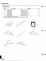
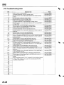
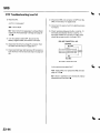
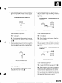
Restraints
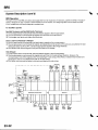
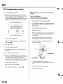
SpecialTools
'
07HAZ-SG00500
8t
oTPM-oo101oo
€
oTsM-TB4o114
O
oTTM-sz5o114
o-'
07TM-0010204
@
-1
o7xAz-s140200
07xAz-s230100
\
DeploymentTool
SCSServiceConnector
r i mu l a t o r
S R SI n f l a t o S
S R SS i m u l a t o rL e a dC
B a c k p r o bA
e dapter1
, 7m m
S R SS i m u l a t o rL e a dE
S R SS i m u l a t o rL e a dF
S R SS i m u l a t o rL e a dH
* 1 : I n c l u d e di n S R ST o o l S e t0 7 M M ' S M 5 0 0 0 8
*2: Use with the stackingpatchcords from T/N 07SAZ-0010004,
BackprobeSet.
o
o
\
J
Gl
@
ro
L .
23-2
SeatBelts
I
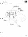
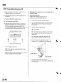
ComponentLocationIndex
REARCENTER
BELTand
REARSEATBELTBUCKLES
step1 on page23-8
page23 9
Inspection,
SHOULDER
ANCHOR
ADJUSTER
step8 on page23-4
FRONTSEATBELT
page23-4
Replacement,
page23 9
Inspection,
I
CHILDSEATTETHER
ANCHORS
Removal/lnstallation,
page23-11
REARSEATBELT
page23.7
Beplacement,
page23-9
Inspection,
FRONTSEAT
BELTBUCKLES
step1 on page23'6
23-3
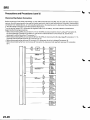
SeatBelts
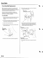
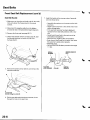
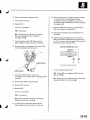
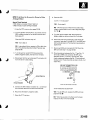
FrontSeat Belt Replacement
SRScomDonentsare locatedin this area.Reviewthe
SRScomponentlocations(seepage23-13)and the
precautionsand procedures(seepage23-14)in the SRS
sectionbefore performingrepairsor service,
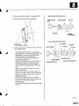
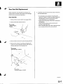
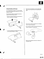
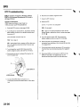
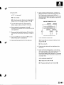
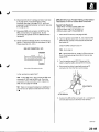
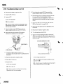
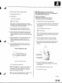
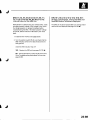
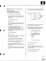
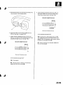
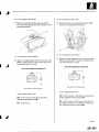
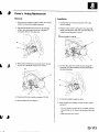
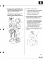
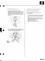
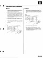
6. Removethe upper anchorcover {A),and remove
t h e u p p e ra n c h o rb o l t( B ) .
B
7/16-20
UNF
32N m (3.3kgf.m,24lbt.ft)
NOTE:Checkthe front seat beltsfor damage,and
replacethem if necessary.Be careful not to damage
them during removaland installation.
Front Seat Belt
1 . Make sure you have the anti-theftcode for the radio,
then write down the frequenciesfor the preset
buttons.
Disconnectthe negativecablefrom the battery,and
wait at least3 minutes beforebeginningwork.
3 . Slidethe front seatforward fully.
Removethe lower anchorcap (A),and removethe
lower anchor bolt (B).
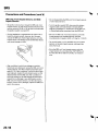
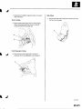
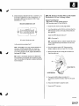
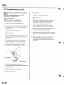
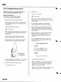
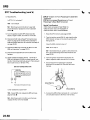
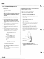
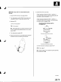
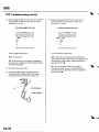
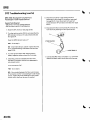
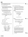
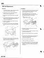
7. Disconnectthe seat belt tensionerconnector(A).
Removethe retractormounting self-tappingET
screw {B),and the retractorbolt (C),then remove
the front seat belt (D) and retractor(E).
6x1.0mm
3.4N m {0.35kgf.m,2.5lbf.ft)
5 . R e m o v et h e r e a rs i d et r i m p a n e l( s e e p a g e 2 0 - 5 1 ) .
7/16-20
UNF
32 N.m(3.3kgf m,2irlbf.ft)
8. lf necessary,removethe front seat belt protecto
(F).
qt
23-4
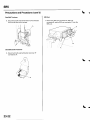
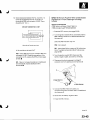
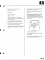
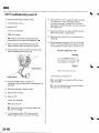
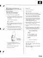
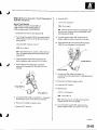
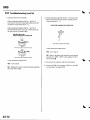
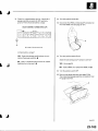
9 . Removethe B-pillaruppertrim {seepage20-50)
1 0 .Removethe shoulderanchoradjuster{A).
Upperanchorbolt construction:
UPPERANCHOR
BOLT
UPPERANCHOR
BUSHING
COLLAR
TOOTHED
LOCKWASHER
Lower anchor bolt construction:
8 x 1.25mm
WASHER
22 N.m(2.2kgf.m,16lbf.ftl
1 1 .Installtheseat belt in the reverseorder of removal,
and note these items:
. lf thethreads on the retractormounting selftapping ET screw are worn out, use an oversized
self-tappingET screw (P/N90133-SZ4-0030)
made specificallyfor this application.
. Checkthat the retractorlockingmechanism
functions(seepage 23-9).
. A s s e m b l et h e w a s h e r sc, o l l a r s a, n d b u s h i n go n
the upper and lower anchorbolts as shown.
. lf the seat belt tensionerhas been deployed
replacethe front seat belt protectorwith a new
one.
. A p p l y l i q u i dt h r e a dl o c kt o t h e a n c h o rb o l t s
beforereinstallation.
. Beforeinstallingthe anchorbolts,make sure
there are no twists or kinksin the front seat belt.
. Make sure the seat belt tensionerconnectoris
pluggedin properly.
. Reconnectthe negativecableto the battery.
. Enterthe anti-theftcode for the radio,then enter
the customer'sradio stationpresets.
. Resetthe clock.
. Do the ECM/PCMidle learn procedure{seepage
11,139).
LOWERANCHORBOLT
TOOTHEDLOCKWASHER
{cont'd)
23-5
Seat Belts
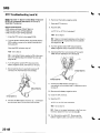
Front Seat Belt Replacement(cont'd)
SeatBelt Buckle
1. Make sure you have the anti-theftcode for the radio,
then write down the frequenciesfor the preset
buttons.
2. Disconnectthe negativecablefrom the battery,
and wait at least3 minutesbefore beginningwork.
3. Removethe front seat (seepage 20-7'1).
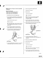
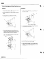
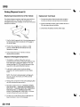
4. Detachthe seat belt switch connectorclip (A),seat
belt buckletensionerconnectorclip (B),and
h a r n e s sc l i p ( C ) .
.-..:.a--
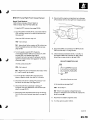
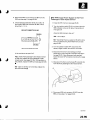
5. Removethe centeranchor bolt (A),and removethe
seat belt buckle{B).
7/16-20
UNF
32N m {3.3kgf m,24lbf.ft)
6. Pullthe seat belt switch/tensionerharness(C)out
through the hole on the seattrack.
23-6
7. Installthe bucklein the reverseorder of removal,
and note these items:
. Assemblethe washerson the centeranchor bolt
as shown.
. Apply liquid thread lockto the centeranchor bolt
before reinstallation.
. lf the seat belt tensionerhas been deployed,
replacethe front seatbelt protectorwith a new
one.
. Apply liquid thread lockto the seat mounting
bolts before reinstallation
. Reconnectthe negativecableto the battery.
. Enterthe anti-theftcode for the radio,then enter
the customer'sradio stationpresets.
. Resetthe clock.
. Do the ECMiPCMidle learn procedure(seepage
11 _ 1 3 9 ) .
COLLAR
I
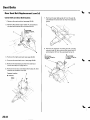
RearSeat Belt Replacement
NOTE:Checkthe rear seat beltsfor damage,and
replacethem if necessary.Be carefulnot to damage
l n di n s t a l l a t i o n .
t h e m d u r i n gr e m o v a a
RearSeatBelt
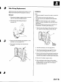
1 . R e m o v et h e r e a rs e a tc u s h i o n( s e ep a g e2 0 8 0 ) .
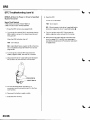
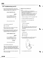
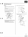
2. Removethe lower anchor bolt {A}.
A
7/16-20UNF
32 N.m (3.3kgf.m,
24 tbf.ftl
l
I
.
\
J
5. Installtheseat belt in the reverseorder of removal,
and note these items:
. lf the threadson the retractormounting selftapping ET screw are worn out, use an oversized
self-tappingET screw (P/N90133-524-0030)
m a d es p e c i f i c a l lfyo r t h i s a p p l i c a t i o n .
. Apply liquid thread lockto the anchorbolt before
reinstallation.
' Checkthat the retractorlockingmechanism
functions{seepage 23-9).
. Beforeinstallingthe anchor bolt, make sure there
are no twists or kinksin the rear seat belt.
,
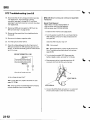
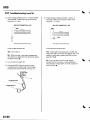
3 , R e m o v et h e r e a rs i d et r i m p a n e l( s e ep a g e2 0 - 5 1 ) .
4 . Removethe retractormounting self-tappingET
screw (A),and the retractorbolt (B),then remove
the rear seat belt (C)and retractor{D).
B
7/16-20
UNF
N m {3.3kgf.m,2irlbf.ft)
A
6x1.0mm
3.4 N.m {0.35kgl m,2.5 lbf.ftl
(cont'd)
23-7
SeatBelts
RearSeat Belt Replacement{cont'd)
CenterBelt and Seat Belt Buckles
1. Removethe seatcushion{seepage 20-80).
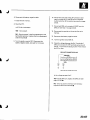
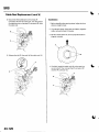
7. Removethe seat belt guide (A)from the pin (B),
and releasethe centerbelt (C)from the seat belt
g ui d e .
2. Removethe centeranchor bolts (A),and remove
the seat belt buckles(B)and centerbeh (C).
A
7/16-20
UNF
32N.m13.3kgf.m,
24 tbt.ft)
'.;r'"
1-..i, ,
<i..
-"':''
"':
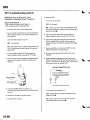
Removethe retractormounting bolt (A),and the
retractorbolt (B),then removethe centerbelt (C)
and retractor(D)from the seat-backframe (E).
3. Removethe right seat-back(seepage 20-80).
A
6x1.0mm
9.8 N.m (1.0kgf m,
7.2 tbl.ttl
7/16-20UNF
32 N.m(3.3kgf m,
24 tbf.ftl
4. Removethe seat-backcover (seepage20-82).
5, Removethe seat-backpad from the seat-back
frame (seestep 3 on page 20-81).
6. Removethe screw,and releasethe hooks (A),then
removethe retractorcover (B).
FastenerLocation
B
.:.',
t.)
23-8
I
Inspec'tion
9. lnstallthe seat belt and bucklesin the reverseorder
of removal,and note these items:
. Checkthat the retractorlockingmechanism
functions(seestep 1 on page 23-10).
. Assemblethe washerson the centeranchor bolt
as shown (exceptcentershoulderbelt).
. Apply liquidthread lock to the anchor bolts
beforereinstallation.
. Beforeinstallingthe centeranchor bolt, make
sure there are no twlsts or kinksin the centerbelt,
Canler anchor bolt construction:
WASHER
with seatbelttensioners.
Forfrontseatbeltretractors
locations(seepage23-13)
reviewtheSRScomponent
(seepsge23-14)in
andprocedures
andthe precautions
the SRSsectionbeforeperformingrepairsor service.
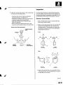
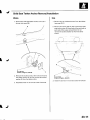
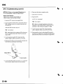
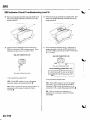
Retractor,Front and Rear
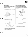
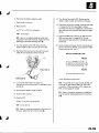
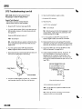
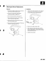
1. Beforeinstallingthe retractor,checkthat the seat
belt can be pulled out freely.
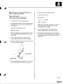
2. l\4akesure that the seat belt does not lockwhen the
retractor(A) is leanedslowly up to 15'from the
mounted position.The seat belt should lock when
the retractoris leanedover 40'. Do not attemDtto
disassemblethe retractor.
Front:
Forward
lnside
Rear:
Forward
Inside
Replacethe seat belt with a new assemblyif there
is any abnormality.Do not disassembleany pan of
the seat belt for any reason,
(cont'd)
23-9
Seat Belts
Inspection(cont'd)
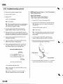
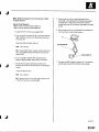
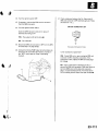
RetraEtor,RearCenter
In-vehicle
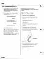
1. Beforeinstallingthe retractor,checkthat the seat
belt can be pulled out freely.
1. Checkthat the seat belt is not twisted or caught on
anything.
2, Make sure that the seat belt does not lockwhen the
retractor(A) is leanedslowly up to 15' from the
mounted position.
2. After installingthe anchors.checkfor free
movementon the anchorbolts. lf necessary,
removethe anchor bolts and checkthat the
washersand other partsare not damagedor
i m p r o p e r l yi n s t a l l e d .
3. Checkthe seat beltsfor damageor discoloration.
Cleanwith a shop towel if necessary.Use only
soap and water to clean.
NOTE:Dirt build-upin the loops of the upper
anchorscan causethe seat beltsto retractslowly.
Wipe the insideof the loops with a cleancloth
d a m p e n e di n l s o p r o p yal l c o h o l .
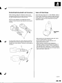
lnside
Forward
3 , Leanthe retractorover 40', and make sure that the
seat belt does not lockwhen pulled out over 900
mm (35.4in.).Do not aftemptto disassemblethe
retractor.
4 . Replacethe seat belt with a new assemblyif there
is any abnormality.Do not disassembleany part of
the seat belt for any reason.
Checkthat the seat belt does not lockwhen pulled
out slowly. The seatbelt is designedto lock only
during a sudden stop or impact.
For rearcentershoulderbelt,checkthat the seat
b e l tl o c k sw h e n p u l l e do u t o v e r 4 0 0m m ( 1 5 . 7i n . )
with the seat-backfolded down.
Make sure that the seat belt will retract
automaticallywhen released.
7 . For each passenger'sseat belt, checkthe seat belt
retractorlockingmechanismALR (automatic
lockingretractor).This function is for securingchild
seats.
- 1 P u l l t h es e a tb e l ta l l t h e w a y o u t t o e n g a g et h e
ALR.The seat belt should retractwith a
ratchetingsound, but not extend.This is
normal.
-2 To disengagethe ALR, releasethe seat belt and
a l l o w i t t o f u l l y r e t r a c tt,h e n p u l l t h es e a tb e l t
out part-way.The seat belt should retractand
extend normally.
8 . Replacethe seat belt with a new assemblyif there
is any abnormality.Do not disassembleany part of
the seat belt for any reason.
\,J
23-10
I
ChildSeatTetherAnchorRemovaUlnstallation
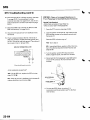
Side
Middle
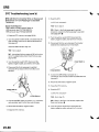
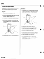
1. Removethe child seattether anchorcover (A) in
t h e r e a rt r i m p a n e l( B ) .
1. Removethe rear bulkheadcoversfrom both sides
( s e ep a g e2 0 - 5 1 ) .
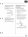
2. Removethe anchorbolt (A),then removethe child
seattether anchor (B)from behindthe seat-backon
each side ofthe cargo compartment.Do not
removethe toothedwasher (C)from the tether
anchor.
f-..- t"
.i..].-
,tltl
8 x 1.25mm
22 N m {2.2ksf.m, 16lbf.ft)
v\
2 . R e m o v et h e a n c h o rb o l t( C ) ,t h e n r e m o v et h e c h i l d
seattether anchor(D).Do not removethe toothed
washer (E)from the tether anchor.
A
I
1
8 x 1 . 2 5m m
22 N.m {2.2kgt m. 16lbfft)
l n s t a l l t h ea n c h o r si n t h e r e v e r s eo r d e ro f r e m o v a l .
3 . I n s t a l l t h ea n c h o ri n t h e r e v e r s eo r d e ro f r e m o v a l .
I J
23-11
sRs
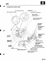
ComponentLocationIndex
LEFTFRONTIMPACTSENSOB
RIGHTFRONTIMPACTSENSOR
SRSINOICATOR
page23-105
Troubleshooting,
SIDEAIRBAG CUTOFFINDICATOR
AIRBAG
DRIVER'S
page23-113
Replacement,
page
Disposal, 23 1'16
FRONTPASSENGER'SAIRBAG
page23-114
Replacement,
Disposap
l , a g e2 3 ' 1 1 6
SENSOR/
SEATBACK
Replacement,
page20-75
FRONTPASSENGER'S
SIDEAIRBAG
Replacement,
p a g e2 3 ' 1 ' 1 5
Disposal,
p a g e2 3 ' 1 1 6
FRONTPASSENGER'S
SEATBELT
TENSIONER
Beplacement,
page23-4
Disposal,
page23-'116
CABLEREEL
Beplacement,
p a g e2 3 - 1 1 9
MEMORYERASE
(MES}
SIGNAL
CONNECTOR
I2PI
OPDSUNIT
page23-27
Initialization,
page23-124
Replacement,
SIOE
PASSENGER'S
IMPACTSENSOR
Replacement,
p a g e2 3 - 1 2 3
DATA LINK
CONNECTOR
(DLCI16P
FRONTPASSENGER'SSEAT
BELTBUCKLETENSIONER
DRIVER'SSEATBELTTENSIONER
page23 4
Replacement,
D i s p o s a pl ,a g e2 3 - 1 1 6
23-13
sRs
Precautionsand Procedures
GeneralPrecautions
Steering-related
Plecautions
Pleaseread the following precautionscarefullybefore
performingairbagsystem service.Observethe
instructionsdescribedin this manual.or the airbags
could accidentallydeploy and causedamageor injuries.
CableReelAlignment
. Exceptwhen performingelectricalinspections.
alwaysturn the ignition switch OFF,disconnectthe
negativecablefrom the battery,and wait at least3
minutesbefore beginningwork.
NOTE:The memory is not erasedeven if the ignition
switch is turned OFFor the batterycablesare
disconnectedfrom the battery.
. Use replacementpans which are manufacturedto the
same standardsand quality as the original parts.Do
not installused SRSpartsfrom anothervehicle.Use
only new pans when making SRS repairs.
. Carefullyinspectany SRS part beforeyou installit.
Do not installany part that shows signs of being
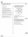
droppedor improperlyhandled,such as dents,cracks,
or deformation.
. Beforeremoving any SRSparts (includingthe
disconnectionof connectors),alwaysdisconnectthe
SRSconnector.
. Use only a digital multimeterto checkthe system.lf it
is not a Honda multimeter,make sure its outout is 10
mA (0.01A)or lesswhen switchedto the lowestvalue
in the ohmmeter range.A testerwith a higheroutput
could causeaccidentaldeploymentand possible
injury.
. Do not put objectson the front passenger'sairbag.
. The original radio has a coded theft protectioncircuit.
Be sure to get the customer'sradio code and write
down the frequenciesfor the radio's presetstations
beforedisconnectingthe batterycable.
. Beforereturningthe vehicleto the customer,enter
the radio code.then enter the customer'sradio
stationpresets,and set the clock.Do the engine
control module (ECM)idle learn procedure(seepage
11-139).
23-14
. M i s a l i g n m e not f t h e c a b l er e e lc o u l dc a u s ea n o p e ni n
t h e w i r i n g ,m a k i n gt h e S R Ss y s t e ma n d t h e h o r n s
inoperative.Centerthe cable reelwheneverthe
following is performed(seestep 6 on page23-121).
-
Installationof the steeringwheel
Installationof the cable reel
I n s t a l l a t i oonf t h e s t e e r i n gc o l u m n
Other steering-related
adjustmentor installation
. Do not disassemblethe cable reel.
. Do not apply greaseto the cable reel.
. lf the cable reel shows any signs of damageor
contamination.replaceit with a new one. For
example,it does not rotatesmoothly.
\rc
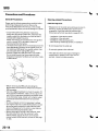
AirbagHandlingand Storage
. Storethe removedairbagon a secure,
flat surface
200'Fi
awayfrom any highheatsource(exceeding
Do not disassemblean airbag,lt has no serviceable
parts.Oncean airbag has been deployed,it cannot be
repairedor reused.
For temporarystorageof an airbagduring service,
observethe following precautions.
. Storethe removedairbagwith the pad surfaceup.
Never put anythingon the airbag.
Never perform electricalinspectionsto the airbags,
such as measuringresistance.
Do not positionyourselfin front of the airbagduring
removal,inspection,or replacement.
To preventdamageto the airbag,keep it free from
any oil, grease,detergent,or water,
Referto the scrappingproceduresfor disposalof a
d a m a g e da i r b a g .
(cont'd)
23-15
sRs
.j
Precautionsand Procedures{cont'dl
SRSUnit, Front lmpact Sensors,and Side
lmpact Sensors
. Do not disassemblethe SRS unit,front impactsensors,
or side impact sensors.
. Be careful not to bump or impactthe SRS unit, front
impact sensors,or side impactsensorswheneverthe
ignition switch is ON (ll),or for at least3 minules after
the ignition switch is turned OFF.
. Turn the ignition switch OFF,disconnectthe battery
negativecable,and wait at least3 minules before
beginninginstallationor replacementof the SBS unit,
or disconnectingthe connectorsfrom the SRSunit.
. During installationorreplacement,be carefulnotto
bump (by impactwrench, hammer,etc.)the area
aroundthe SRS unit, front impact sensors,and sjde
impact sensor.The airbagscould accidentallydeploy
and causedamageor injury.
. Be sure the SRSunit,front impactsensors,and side
impact sensorsare installedsecurely.with the
mounting bolts torquedto 9.8 N.m (1.0kgf.m,7.2 lbf.ft)
. Do not spill wateroroil on the SRSunit, front impact
sensors,or the side impact sensors,and keepthem
away from dust.
. Store the SRS unit, front imDactsensorsand side
impactsensorsin a cool (lessthan 104"F/40'C)and
dry (lessthan 80 % relativehumidity,no moisture)
area.
After a collisionin which any airbagsor seat belt
tensionerswere deployed.replacethe SRSunit, front
impact sensors,and other relatedcomponents(see
page 23-112).After a collision in which a side airbag
was deployed.replacethe side impact sensoron the
deployedside and the SRS unit. After a collisionin
which the airbagsor the side airbagsdid not deploy,
inspectfor any damageor any deformationon the
SRS unit, front impact sensors,and the side impact
s e n s o r sl.f t h e r ei s a n y d a m a g e r, e p l a c et h e S R Su n i t
and/orthe sensors.
23-16
I
I
WiringPrecautions
Precautions
for ElectricalInspections
Some of the SRSwiring can be identifiedby a special
yellow outer covering,and the SRSconnectorscan be
identifiedby their yellow color.
Observethe instructionsdescribedin this section.
. When using electricaltestequipment,insertthe
probe of the tester into the wire side of the connector.
Do not insertthe probe of the testerinto the terminal
side of the connector,and do not tamper with the
connector.
. Neverattemptto modify. splice,or repairSRSwiring.
l f t h e r ei s a n o p e no r d a m a g ei n S R Sw i r i n g ,r e p l a c e
the harness.
Use a U-shapedprobe.Do not insertthe probe
forcibly.
J
Be sure to installthe harnesswires so they do not get
Dinchedor interferewith other Darts.
Use specifiedserviceconnectorsin tro u bleshooting.
U s i n gi m p r o p e rt o o l sc o ul d c a u s ea n e r r o ri n
inspectiondue to poor metal-to-metalcontact.
M a k es u r ea l l S R Sg r o u n dl o c a t i o n sa r e c l e a n ,a n d
groundsare securelyfastenedfor optimum metal-tometal contact.Poorgroundingcan causeintermittent
problemsthat are difficultto diagnose.
(cont'd)
23-17
sRs
Precautionsand Procedures(cont'dl
Spring-loaded
LockConnector
Side Airbag Connector:
Some SRSsystemconnectorshave a spring-loaded
lock.
Disconnecting
T o r e l e a s et h e l o c k ,p u l l t h es p r i n g - l o a d esdl e e v e( A )
a n dt h e s l i d e r{ B )w h i l e h o l d i n gt h e o p p o s i t eh a l fo f t h e
connector.Then pullthe connectorhalvesapart.Be
sure to pull on the sleeveand not on the connectorhalf.
Front Airbag Connectors:
Disconnecting
To releasethe lock.pullthe spring-loadedsleeve(A)
toward the stop (B)while holdingthe oppositehalf of
the connector.Then pullthe connectorhalvesapart,Be
sure to pull on the sleeveand not on lhe connector.
Connecting
1. To reconnect,hold the pawl-sideconnector,and
presson the backof the sleeve-sideconnectorin
the directionshown. As the two connectorhalves
are pressedtogether,the sleeve(A) is pushedback
by the pawl (C).Do not touch the sleeve.
Connecting
Hold both connectorhalves,and pressthem firmly
togetheruntil the projection(C)of the sleeveside
connectorclicks.
J
When the connectorhalvesare completelV
connected,the pawl is released,and the springloadedsleevelocksthe connector.
\ J
23-18
Backprobing
Spring-loaded
LockConnectors
Seatswith SideAirbags
When checkingvoltageor resistanceon this type of
connectorthe first time, you must removethe retainer
to insertthe tester orobe from the wire side.
"SIDEAIRBAG" label
Seatswith side airbagshave a
on
the seat-back.Becausethe componentpans (seat-back
cover,cushion,etc.)of seatswith and without airbags
are different,make sure you installonly the correct
replacementparts.
NOTE:lt is not necessaryto reinstallthe removed
retainer;theterminalswill stay lockedin the connector
housrno.
A
To removethe retainer(A),inserta flat-tipscrewdriver
(B) betweenthe connectorbody and the retainer,then
carefullypry out the retainer.Takecare not to breakthe
connector.
W h e n c l e a n i n gd, o n o t s a t u r a t e t h es e a t w i t hl i q u i d ,
and do not sDravsteam on the seal
Do not reoalra torn or fraved seat-backcover.
ReDlacethe seat-backcover.
A f t e ra c o l l i s i o ni n w h i c ht h e s i d ea i r b a gw a s
deployed,replacethe side airbagwith new parts.lf
the seat-backcushion is split, it must be replaced.lf
the seat-backframe is deformed,it must be replaced.
Never put aftermarketaccessorieson the seat{covers,
pads,seat heaters,lights,etc.).
(cont'd)
23-19
sRs
Precautionsand Procedures(cont'dl
DisconnectingSystemConnectors
Beforeremoving a front airbag.side airbag,or other SRS relateddevices{the SRS unit,the cable reel,the front impact
sensors,the side impact sensors,the seat belt buckletensioners,and the seat belt tensionerconnector),disconnecting
connectorsfrom relateddevices,or removingthe dashboardor the steeringcolumn, disconnectthe airbagconnectors
or the side airbagconnectorsto preventaccidentaldeploVment.
Turn the ignition switch OFF,disconnectthe negativecablefrom the battery,and wait at least3 minutesbefore
beginningthe following procedures.
'BeforedisconnectingSRSunitconnectorA(1)fromtheSRSunit,disconnectthedriver'sairbag4Pconnector(3).
the front passenger'sairbag4P connector(4),the driver'sseat belt tensioner2P connector(6),and the front
passenger'sseatbelt tensioner2P connector(7).
. BeforedisconnectingSRS unit connectorB (8)from the SRS unit, disconnectboth side airbag2P connectors(11.'12),
and both seat belt buckletensioner4P connectors(9, 10).
. Beforedisconnectingthe cable reel 4P connector(2),disconnectthe driver'sairbag4P connector(3).
'Beforedisconnectingthefloorwireharness4Pconnector(5),disconnectbothseatbelttensioner2Pconnectors
(6.7).
\
23-20
.
1. Disconnectthe batterynegativecable,and wait at
least3 minutes.
Driver's Airbag
Side Airbag
4. Disconnectboth side airbag2P connectors(Alfrom
the floor wire harness.
2. Removethe accesspanel (A)from the steering
wheel,then disconneclthe driver'sairbag 4P
connector(B)from the cable reer.
Front Passenger'sAirbag
3. Disconnectthe front passenger'sairbag4P
connector(A)from dashboardwire harnessB.
(cont'd)
23-21
sRs
Precautionsand Procedures(cont'd)
SeatBelt Tensioner
bothseatbelttensioner2Pconnectors
5. Disconnect
(A)fromthefloorwire harness
4
SRS Unit
7. DisconnectSRS unit connectorA, SRS unit
connectorB, and/or SRS unit connectorC from the
S R Su n i t .
Seat Belt Buckle Tensioner
6. Disconnectboth seat belt buckletensioner4P
connectors(A).
\ J
23-22
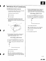
GeneralTroubleshooting
Information
DTC(Diagnostic
TroubleCodesl
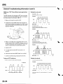
Readingthe DTC
The self-diagnostic
function of the SRSsystem allows it
to locatethe causesof system problemsand then store
this informationin memory. For easiertroubleshooting,
this data can be retrievedvia a data link circuit.
When the SRSindicatoris on, read the DTCusing either
of the following methods:
. W h e ny o u t u r n t h e i g n i t i o ns w i t c hO N ( l l ) ,t h e S R S
indicatorwill come on. lf it goes off after 6 seconds,
the system is normal.
. lf there is an abnormality,the svstem locatesand
definesthe problem,storesthis informationin
memory, and turns the SRS indicatoron. The data
w i l l r e m a i ni n t h e m e m o r ye v e nw h e n t h e i g n i t i o n
switch is turned off or if the batteryis disconnected.
. When you connectthe HondaPGlMTesterto the 16P
d a t al i n kc o n n e c t o(rD L C ) t os h o r tt h e S C St e r m i n a l ,
a n d t u r n t h e i g n i t i o ns w i t c hO N ( l l ) .t h e S R Si n d i c a t o r
will indicatethe diagnostictrouble code (DTC)by the
n u m b e ro f b l i n k s .
. When you connectthe HondaPGM Testerto the 16P
data link Connector(DLC),you can retrievethe DTCin
t h e H o n d aS y s t e m s" S R S " m e n u .
. After readingand recordingthe DTC,proceedwith
the troubleshootingprocedurefor th is code.
PGM Tester "SRS" Menu Method:
Connectthe Honda PGM Tester{A)to the 16Pdata link
connector{DLC)(B),
and follow the Tester'sDromptsin
"SRS"
the
menu.
lf the Testerindicatesno DTC,no communication.DTC
3-6 to 3-'10,DTC4-6 to 4-10,DTC9-1,or DTC9-2,
double-checkby usingthe "SCS" menu method.
Precautions
. U s eo n l y a d i g i t a lm u l t i m e t etro c h e c kt h e s y s t e m .l f
it's not a Hondamultimeter,make sure its output is
1 0 m A ( 0 . 0 1 Ao) r l e s sw h e n s w i t c h e dt o t h e s m a l l e s t
v a l u ei n t h e o h m m e t e rr a n g e A
, t e s t e rw i t h a h i g h e r
o u t p u tc o u l dd a m a g et h e a i r b a gc i r c u i to r c a u s e
a c c i d e n t aal i r b a gd e p l o y m e nat n d p o s s i b l ei n j u r y .
. Wheneverthe ignition switch is ON (ll),or has been
turned OFFfor lessthan 3 minutes,be careful not to
b u m pt h e S R Su n i Ut h e a i r b a g sc o u l da c c i d e n t a l l y
d e p l o ya n d c a u s ed a m a g eo r i n j u r i e s .
. Beforeyou removethe SRSharness,disconnectthe
driver's airbagconnector.the front passenger's
airbagconnector,both side airbagconnectors,both
seat belt buckletensionerconnectors,and both seat
b e l tt e n s i o n ecr o n n e c t o r s .
. Make sure the batteryis sufficientlycharged.lf the
batteryis dead or low, measuringvalueswon't be
correct.
. Do not touch a tester probe to the terminalsin the
SRSunit or harnessconnectors,and do not connect
t h e t e r m i n a l sw i t h a j u m p e rw i r e . U s eo n l y t h e
backprobeset and the HondaPGM Tester.Backprobe
spring loadedlocktype connectorscorrectly.
(cont'd)
23-23
sRs
L
GeneralTroubleshootingInformation(cont'd)
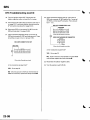
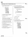
PGM Tester "SCS" Menu Method {retrieving the flash
codes):
The SRSindicator(A) indicatesthe DTCby lhe number
of blinkswhen the Honda PGM Tester(B) is connected
to the DLC(datalink connector)( 16P)(1).
'1.
Readingthe main code:
I nc a s eo f 1 - 1 0
Countthe numberof blinks.
Examplo:
1 . 2S r . 2S 1 . 2S 1 . 2S 1 . 2S
*t**t*l*l
""_f]_flfl
Make sure the ionition switch is OFF.
2. Connectthe HondaPGN4Tester(B)to the DLC(C),
"SCS" menu
and follow the Tester'soromDtsin the
(see
ground
to
the SCS line
the HondaPGM Tester
ODerator'sManual).
4
+
Maincodo= 1
1
+
=3
1
In caseot 11..'15
Fourfastblinkscountas 10.
Add anyfunherblinkstogetheras shown.
Example:
0 . 1s
,A
/// t\\\
_
1.rs r.2s r.2s 1.2s
*t*
- L'- - * l
//lii\\
|
""ffi
Main code=
3 . Make sure the SCS line is grounded,then turn the
ignitionswitch ON (ll).The SRS indicatorcomes on
for about 6 seconds,and then goes off. Then it will
blinkto indicatethe DTC(seethe table below).
=12
I
10
l n c a s eo f 2 0 o r m o r e
T w o s e t s o f f o u r f a s t b l i n k sc o u n t a s 2 0 .
A d d a n y f u n h e r b l i n k s t o g e t h e ra s s h o w n .
Examplo:
0 . 1s
4. Readthe DTC.
0.1s
12s12s
,y'fl\,,. /[N *l*FtftffN*+fH-t-ff
5 . Turn the ignition switch OFF,and wait for 10
seconds.
6, Disconnectthe Honda PGMTesterfrom the DLC.
7. Do the troubleshootingprocedurefor the DTC.
Patteins of DTC Indications:
Main code=
10
+
10
Readingthe subcode:
Count
thenumber
of blinks.
T h e D T C c o n s i s t so f a m a i n c o d e a n d s u b c o d e .
Example:
S: Second
6S
25
o N
[ l I t l - l- - - -|- L [l - - - l
oFFl
First emitting Main code
0.3s 0.3s 0.3s 0.3s 0.3s 0.3s 0.3s
l**t**t*t*t*l
35
Subcode
I
""ffi
S
u
b
c
o
d
lf the main code is
DTC 3 4.
e
'3',
=
1
+
1
+
1
a n d t h e s u b c o d ei s
r
'
1
=
4
' 4 ' , r e c o r da
\ J
23-24
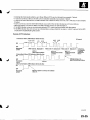
Includingthe most recentproblem,up to three differentDTCScan be indicated(seeexample 1 below).
ln case of a continuousfailure,the DTCwill be indicatedrepeatedly{seeexample 1 below).
In caseof an intermittentfailure,the SRS indicatorwill indicatethe DTCSone time, then it will stay on (seeexample
2 below).
lf both a continuousand an intermittentfailure occur,both DTCSwill be indicatedas continuousfailures.
When the system is normal (no DTCS),the SRS indicatorwill stay on (seeexample3).
lf the SRSindicatorcomes on continuouslywithout a DTC,there mav be a problemwith the svstem.
lf the SRSindicatordoes not come on as indicatedabove,alwayscheckfor an open or a short to ground in the SCS
circuitbeforetroubleshootingthe system.
Example of DTC Indications:
1. Continuousfailure,SRSIndic6torblink$likethis:
1 . 2S 1 , 2S
0.3s
0.3s 0.3s
S: Second
ON
OFF
Bulb check
period
Maincode(21 Subcode
l1)
Main code l1l Subcode(3) Main code {11 Subcode{'l) Indications
are lepeated
DTC2-l
tn cese ot
DTC1-3
DTC1-1
Most recentp.oblem
continuous
Sscond-mostrecent
Third-mostrocent
problem
problem
failure.
2. Intermittent failure, SRS lndicator blinks like this:
ON
OFF
Bulb check
DTC 5-1
period
(no
3. Normal
failure|,SRSIndicatorblinks like this:
lndicator stays on in
case of i nterm ittent failu re.
ON
OFF
Bulb chock
period
No DTC,systom is normal, the indicator
stays on.
(cont'd)
23-25
sRs
GeneralTroubleshootingInformation(cont'dl
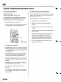
Erasingthe DTGMemory
Troubleshootinglntermittent Failures
Specisl Tool Required
SCSserviceconnector07PAz-0010100
lf there was a malfunction,but it doesn't recur.it will be
storedin the memory as an intermittentfailure,and the
SRS indicatorwill come on.
To erasethe DTC(S)fromthe SRSunit, use a Honda
PGMTester{seelhe HondaPGfMTesterSRSVehicle
SystemSupplement)or the following procedure.
1. Make sure the ignition switch is OFF.
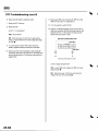
2. Connectthe SCSserviceconnector{A) to the MES
2P connector(B).Do not use a jumper wire.
After checkingthe DTC,troubleshootas follows:
1. Readthe DTC(see"Readingthe DTC").
"Erasingthe DTC
2. Erasethe DTCmemory (see
Memory").
3. With the shift lever in neutral,startthe engine,and
letit idle.
4 . The SRSindicatorwill come on for about 6 seconds
and then go off.
Shakethe wire harnessand the connectors.take a
test drive (quickacceleration,quick braking,
cornering),turn the steeringwheel fully left and
'10
seconds.lf the
right, and hold it there for 5 to
problem recurs,the SRSindicatorwill come on.
07PAZ-0010100
lf you can't duplicatethe intermittentfailure,the
system is OK at this time.
3 . T u r nt h e i g n i t i o ns w i t c hO N ( l l ) .
4. The SRS indicatorwill come on for about 6 seconds,
and then go off. Removethe SCSserviceconnector
from the MES connectorwithin 4 secondsafterthe
indicatorgoes off.
5. The SRS indicatorwill come on again.Reconnect
the SCSserviceconnectorto the MES connector
within 4 secondsafter the indicatorcomes on.
6. When the SRSindicatorgoes off, removethe SCS
serviceconnectorfrom the MES connectorwithin 4
seconds.
7 . T h e S R Si n d i c a t ow
r i l l b l l n kt w o t i m e s i n d i c a t i n g
that the memory has beenerased.
8. Turn the ignition switch OFF,and wait for
seconds.
'10
. h e S R Sj s
9 . T u r nt h e i g n i t i o ns w i t c hO N ( l l )a g a i n T
OK if the SRSindicatorcomes on for 6 secondsand
then goes off.
23-26
\ J
I
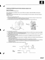
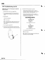
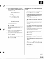
Initializingthe OPDS{OccupantPositionDetectionSystem}Unit
Special Tool Required
SCSserviceconnector07PAz-00'1
0100
When a seat-backcover,seat-backcushion,and/or OPDSunit is replaced,initializethe OPDSby following the
procedurebelow.
NOTE:Make sure the front passenger'sseat is dry. Set the seat-backin the normal position,and make sure there is
nothing on the seat.
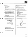
'1.
l\4akesure the ignition switch is OFF.
2. Connectthe HondaPGM Tester(A)to the DLC(16P)(B),andfollowtheTester's prompts jn the ,,SCS,,menu to
ground the SCSline (seethe Honda PGM TesterOperator'sManuaD.
3. Connectthe SCSserviceconnector(C)to the MES 2P connector(D).Do not use a iumoer wire.
c
07PAZ-00r0100
4 . T u r nt h e i g n i t i o ns w i t c hO N { l l ) .
5. The SRS indicatorcomes on for about 6 secondsand goes off. Removethe SCSserviceconnectorfrom the MES
connectorwithin 4 secondsafterthe SRSindicatorwent off.
6. The SRSindicatorcomes on again.Reconnectthe SCSserviceconnectorto the MES connectorwithin 4 seconds
afterthe SRS indicatorcomes on.
7. The SRSindicatorgoes off. Removethe SCSserviceconnectorfrom the MES connectorwithln 4 seconds.
8. Watch the sRS indicator.
'lftheindicatorblinkstwotimesandthenstayson,theOPDSisinitialized.buttheDTCSneedtobeerased.
step 9, then erasethe DTCS.
.lftheindicatorblinkstwotimesandthengoesoff,theOPDSunitisinitialized.Gotostep9.
' lf the indicatorstayson without first blinking.theOPDSis not initialized.Readthe DTC.lf DTC 15-'lis indicated,
repeatthe initializationprocedure.lf anotherDTCis indicated,go to the appropriatepage in the DTC
TroubleshootingIndex.
9. Turn the ignition switch off, and disconnectthe PGM Tester.
SBS indic.ror
MES
I J
DISCONNECTED
23-27
sRs
t .
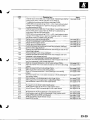
DTCTroubleshootingIndex
DTC
t- |
t-5
1-4
t-5
2-1
2-2
2-3
2-4
2-5
3-1
3-2
3-3
3-4
3-5
21-1
2't-4
2't-5
4-'l
4-2
4-3
4-4
4-5
22-3
22-4
22-5
5-1
5-2
5-4
5-8
6-3
6-4
Detection ltem
O D e ni n d r i v e r ' sa i r b a qi n f l a t o r
Increasedresistancein driver'sairbaq inflator
Shon to anotherwire or decreasedresistancein driver's airbag
inflator
Shortto Dowerin driver'sairbao inflator
Shortto qround in driver'sairbaq inflator
Open in front Dassenqer's
airbaq inflator
I n c r e a s e rde s i s t a n cien f r o n tp a s s e n q e r 'asi r b a qi n t l a t o r
Short to anotherwire or decreasedresistancein front passenger's
airbao inflator
Short to oower in front oassenoer'sairbaq inflator
Short to qround in front passenqer'sairbaq inflator
ODenin driver'sseat belttensioner
lncreasedresistancein driver's seat belt tensioner
Short to anotherwire or decreasedresistancein driver'sseat belt
tensioner
Short to oower in driver'sseat belt tensioner
Short to oround in driver'sseat belt tensioner
ODenor increasedresistancein driver'sseat belt buckletensioner
Short to anotherwire or decreasedresistancein driver'sseat belt
buckletensioner
Short to Dowerin driver'sseat belt buckletensioner
Shon to oround in driver'sseat belt buckletensioner
ODenin front oassenoer'sseat belt tensioner
lncreasedresistancein front oassenqer'sseat belttensioner
Short to anotherwire or decreasedresistancein front passenger's
seat belt tensioner
seat belt tensioner
Shon to Dowerin front Dassenqer's
Short to qround in front oassenoer'sseat belt tensioner
Open or increasedresislancein front passenger'sseat belt buckle
tensioner
Short to anotherwire or decreasedresistancein front passenger's
seat belt buckletensioner
Short to oower in front oassenqer'sseat belt buckletensioner
Short to oround in front oassenoer'sseatbelt buckletensioner
lnternalfailure of SRSunit
NOTE:
BeforetroubleshootingDTCS5-1 through 8-6,checkbattery/system
voltage.lf the voltage is low, repairthe charging system before
troubleshootinothe SRS.
Notes
(seeDaqe23-36)
(seeDaoe23-36
(seepage23-37)
(seepaqe23-39
{seepaqe23-40
{seeoaoe23-42
(seeoaqe 23-42
(seepage23-43)
(seepaqe23-45
(seepaqe 23-46
(seepage 23-48
(seepaqe 23-48
(seepage 23-49)
(seeDaqe23-51
(seeoaoe 23-52
(seepaqe 23-54
(seepage23-55)
(seepaqe 23-56)
(seeoaqe23'57
{seepage23-58)
{seepaqe23-58)
{seepage23-60)
t J
lsee oaqe23-61
(seeDaqe23-63
(seepage 23-64)
(seepage 23-65)
(seepaqe 23-66
(seepaqe 23-68
(seepage23-69)
6-7
6-8
1-)
7-3
8-1
a-2
8-4
8-5
8-6
23-28
\ J
I
J
DTC
9-1
Detection ltem
Internalfailure of the SRS unit. lf intermittent,it could mean internal
failure of the unit or a faulty indicatorcircuit.Referto
TroubleshootingIntermittentFailures(seepage 23-26).
NOTE:BeforetroubleshootingDTC9-1 or 9-2,checkbattery/system
voltage.lf the voltage is low, repairthe chargingsystem before
t r o u b l e s h o o t i nt gh e S R S .
Internalfailure of the SRSunit. lf intermittent,it could mean internal
failure of the power supply (VB line).Referto Troubleshooting
IntermittentFailures(seepage 23-26).
NOTE:BeforetroubleshootingDTC9-1 or 9-2,checkbattery/system
voltage.lf the voltage is low, repairthe chargingsystem or replace
the b€tterybeforetroubleshootingthe SRS.
Faultydriver'sseat belt buckleswitch
9-2
9-3
9-4
9-6
9-7
FaultLtglt passenger's
seatbeltbuckleswitch
FaultyIeft front imDactsensor
Faultyright front impact sensor
Seat belt and seat belt buckletensioners(and airbag(s))deployed
D r i v e r ' ss i d ea i r b a gd e p l o y e d
Seat belt and seat belt buckletensioners(and airbag(s))and driver's
s i d ea i r b a gd e p l o y e d
Frontpassenqer'sside airbaodeDloved
Seat belt and seat belt buckletensioners(and airbag(s))and front
passenqer'sside airbaq deDloved
Driver'sand front passenqer'sside al
Seat belt and seat belt buckletensioners(and airbag(s))and driver's
and front passenger'sside airbagsdeployed
Open or increasedresistancein driver's side airbao inflator
Short to anotherwire or decreasedresistancein driver'sside airbao
inflator
Short to power in driver'sside airbaq inflator
Short to ground in driver's side airbaq inflator
Open or increasedresistancein front passenger'sside airbag
inflator
Short to anotherwire or decreasedresistancein front passenger's
side airbag inflator
Short to power in front passenqer'sside airbaq inflator
S h o r tt o g r o u n di n f r o n t p a s s e n g e r 'ssi d ea i r b a qi n f l a t o r
Internalfailure of the driver's side impactsensor
10-1
10-2
r0-3
'10-4
'10-5
10-6
l r
10-7
11-1
11-4
I t-5
12-4
Iz-5
13-1
N o s i g n a lf r o m t h e d r i v e r ' ss i d ei m p a c ts e n s o r
- 7
13-4
14-1
i i
14-3
14-4
15-1
15-2
15-3
,
Notes
(seepage23-69)
(seeDaqe23-71)
lgqgfage 23-74)
{see Daqe23-77)
(seepaqe 23-79)
(seepage23-69)
( s e ep a q e2 3 - 8 1 )
(seepage23-82)
(seeoaqe 23-83)
{seepaqe 23-85)
(seepage 23-86)
(seepage 23-87)
{seeDaqezJ-uu}
(seeoaqe 23-90)
(seepage 23-70)
( s e ep a q e2 3 - 9 1 )
Faultypowersupplyto the df,rglllug t Opacts9I99L
Internalfailureofthe frontpassenger's
sideimpactsensor
(seepage23-92)
(seepage23-70)
N o s i g n a lf r o m t h e f r o n t p a s s e n g e r 'ssi d ei m p a c ts e n s o r
Faultypower supply to the front passenqer'sside impact sensor
F a u l t vO P D Su n i to r O P D Sn o t i n i t i a l i z e d
Faultyside airbagcutoff indicatorcircuit
FaultyOPDSsensor
(seepaqe 23-94)
(seepage 23-95)
( s e ep a q e2 3 - 9 6 1
(seeDaqe23-99)
(seeoaoe 23-104)
I J
23-29
SRS
\
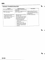
Symptom TroubleshootingIndex
Symptom
SRSindicatordoesn'tcome on
SRSindicatorstayson when in
"SCS" menu method
Slde airbagcutoff indicatorstays
o n a f t e rb u l bc h e c k( l f t h e
indicatorstayson, it does not set
a DTC).Side airbagcutoff
indicatoris flashing
Diagnosticprocedure
S R SI n d i c a t oTr r o u b l e s h o o t i n(gs e e
p a o e2 3 - 1 0 5 )
SRSIndicatorTroubleshooting(see
step 1 on page 23-107)
. M a k es u r en o t h i n gi s o n t h e f r o n l
passenger'sseat.
. lf the side airbagcutoff indicator
stayson after the ignition switch
i s t u r n e dO N ( l l ) ,i n i t i a l i z teh e
OPDSunit (see page23-271.
- lf the side airbagcutoff
i n d i c a t o or p e r a t e sn o r m a l l Yt,h e
system is OK.
- lf the side airbagcutoff
indicatorstayson, replacethe
nUl.
u F U 5 S e n S O{ rS e eS e C r O Z
The sensor is part of the seatback Dad.
4
Also check for
Inabilityto retrieveDTCswith the
PGM Tester.Retrievethe flash
codes usingthe SCSmenu method
(seepage 23-24).
DTC 15-2troubleshooting
t r J
\ J
23-30
I
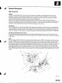
SystemDescription
SRSComponents
Airbags
The SRSis a safetydevicewhich, when used with the seat belt, is designedto help protectthe driver and front
passengerin a frontal impact exceedinga certainset limit. The system consistsofthe SRS unit, includingsafing
sensorand impactsensor(A),the cable reel (B),the driver's airbag(C),the front passenger,sairbag (D).seat belt
tensioners(l),seat belt buckletensioners(J), and front impactsensors(K).
Sincethe driver'sand front passenger'sairbagsusethe same sensors,both normally inflateat the same ttme.
However,it is possiblefor only one airbagto inflate.This can occurwhen the severityof a collision is at the margin,or
threshold,that determineswhether or not the airbagswill deploy.In such cases,the seat belt will provide sufficient
protection,and the supplementalprotectionofferedby the airbagwould be mininal.
Side Airbags
The side airbags(E)are in eachfront seat-back.They help protectthe upper torso of the driver or front seat passenger
during a moderateto severeside impact.Side impact sensors(F) in each door sill and in the SRS unit detectsuch an
impactand instantlyinflatethe driver'sor the passenger'sside airbag.Only one side airbagwill deploy during a side
impacl. lf the impact is on the passenger'sside,the passenger'sside airbagwill deploy even if there is no passenger.
Seat Belt and Seat Belt Buckle Tensioners
The seat belt and seat belt buckletensionersare linkedwith the SRSairbagsto further increasethe effectivenessof
the seat belt. ln a front-endcollision,the tensionersinstantlyretractthe belt and bucklefirmly to securethe occupants
in their seats.
I
OPDS
The side airbagsystemalso includesan occupantpositiondetectionsystem (OpDS).This systemconsistsof sensors
( G ) a n da n O P D Su n i t( H )i n t h e f r o n t p a s s e n g e r 'sse a t - b a c kT.h e O P D Su n i t s e n d so c c u p a nht e i g h la n d p o s i t i o nd a t at o
the SRS unit. lf the OPDSunit determinesthat the front passengeris of small stature(for example,a child) and the
front passengeris leaninginto the side airbag deploymentpath,the SRSunit will automaticallydisablethe passenger's
side airbag.The SRSunit will also disablethe airbagwhen the OPDSdetectscertainobiectson the seat.When the
side airbag is disabled,the side airbagcutoff indicatoron the instrumentpanel alertsthe driver that the passenger's
side airbagwill not deploy in a side impact.When the object is removed,or the passengersits upright,the side airbag
cutoff indicatorwill go off after a few seconds,alertingthe driver that the passenger'sside airbagwill deploy in a side
imDact.
(cont'd)
23-31
sRs
SystemDescription(cont'dl
!J
SRSOperation
The main circuit in the SRS unit sensesand judgesthe force of impact and, if necessary.ignitesthe inflatorcharges.lf
batteryvoltage is too low or power is disconnecteddue to the impact,the voltage regulatorand the back-uppower
circuit,respectively,will keepvoltageat a constantlevel.
For the SRS to operate:
Seat Belt Tensioners and Seat Belt Buckle Tensioners
(1)A front impact sensormust activateand send electricsignalsto the microprocessor.
(2)The microprocessormust computethe signalsand send them to the tensioners.
(3)The chargesmust ignite and deploy the tensioners.
Driver's and Front Passenger'sAirbagls)
(1)A front impactsensor musl activate.and send electricsignalsto the microprocessor.
(2)The microprocessormust computethe signals.and dependingon the severityof the collisionand whetherthe seat
belt buckleswilch is ON or OFF,it sendsthe appropriatesignalsto the airbag inflator(s).
(3)The inflatorsthat receivedsignalsmust ignite and deploy the airbags.
Side Airbaglsl
( 1)A side impact sensormust activate,and send electricsignalsto the microprocessor.
(2)The microprocessormust computethe signalsand send them to the side airbag inflator(s).However,the
microprocessorcuts off the signalsto the front passenger'sside airbag if the OPDSunit determinesthat the tront
passenger'shead is in the deploymentpath of the side airbag.
(3)The inflatorthat receivedthe signal must ignite and deploythe side airbag.
lw$ad..n sl
T'
n0m
S I
P gsfrlctR
S oXrVEr
9oEAiA$ SOtlr&G I
J
sEctto
f'**)r !
\ J
23-32
Self-diagnosis System
A self-diagnosiscircuitis built into the SRS uniUwhen the ignition switch is turned ON (ll),the SRS indicatorcomes on
and goes off after about 6 secondsif the SRS is operatingnormally.
lf the indicatordoes not come on, or does not go off after 6 seconds.or if il comes on while driving, it indicatesan
abnormalityin the SRS.The SRSmust be inspectedand repairedas soon as possible.
For betterserviceability,the SRSunit memory storesa DTCthat relatesto the causeof the malfunction,and the unit is
connectedto the data link circuit.This informationcan be read with the Honda PGM Testerwhen it is connectedto the
data link connector(DLc) (seepage 23-23).
23-33
SRS
J
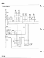
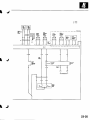
CircuitDiagram
srarsftr
rrl$0[n
rrssf c s
r-----Tr-i
4
i___':--_:"1
\ J
23-34
I
J
tr ozr"*
tr ul"ar
NJfl
t
I
1i
l
|-(tzl
J
I J
23-35
sRs
J
DTCTroubleshooting
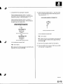
DTC1-1:Openin Driver'sAirbagInflator
Resistance
in Driver's
DTC1-2:Increased
AirbagInflator
Special Tools Required
. SRS inflatorsimulator07SAZ-TB4011A
. SRSsimulatorlead F 07XAZ-S230100
6. Reconnectthe batterynegativecable.
7. Erasethe DTCmemory.
8. Readthe DTC,
ls DTC 1-1or DTC 1-2indicated?
1. Erasethe DTCmemory (seepage 23-26).
YES-Go to step 9.
2. Turn the ignition switch ON {ll),and checkthat the
SRSindicatorcomes on for aboul 6 secondsand
then goes off.
NO Open or increasedresistancein the driver's
airbag inflator;replacethe driver'sairbag (seepage
23-113).t
9. Turn the ignition switch OFF.Disconnectthe
batterynegativecable,and wait ior 3 minutes.
Does the SBS indicator stay on?
YES-Go to step 3.
NO Intermittentfailure,system is OK at this time.
Go to TroubleshootingIntermittentFailures(see
page 23-26).
3. Turn the ignition switch OFF.Disconnectthe
batterynegativecable,and wait for 3 minutes.
4. Disconnectthe driver's airbag4P connector(A)
from the cable reel.
07sAz-TB4011A
07xaz-s230100
5. Connectthe SRS inflatorsimulator(2 Q
connectors)and the simulatorlead F to the cable
reet.
23-36
10. Disconnectthe front passenger'sairbag4P
connectorfrom dashboardwire harnessB (seestep
3 o n p a g e2 3 - 2 1 ) .
11. Disconnectboth seat belt tensioners2P connectors
from the floor wire harness(seestep 5 on page23-
22t.
1 2 . D i s c o n n e cSt R Su n i tc o n n e c t oA
r ( 1 8 P ) f r o mt h e
SRSunit (seestep 7 on page 23-22).Do not
disconnectthe specialtool from the cable reel.
a
13. Checkresistancebetweenthe No. 7 and the No.
t e r m i n a l sa n d b e t w e e nt h e N o . 6 a n d t h e N o . 1 5
r ( 1 8 P )T. h e r e
t e r m i n a l so f S R Su n i tc o n n e c t oA
s h o u l db e 2 . 0 3 . 0 0 .
'16
SRSUNITCONNECTOR
A I18P)
DTC1-3:Shortto AnotherWire or Decreased
in Driver'sAirbagInflator
Resistance
SpecialToolsRequired
. SRS inflatorsimulator07SAZ-T8401
1A
. SRSsimulatorlead F 07XAZ-S230100
1. ErasetheDTCmemory (seepage 23-26).
2. Turn the ignition switch ON (ll),and checkthat the
SRS indicatorcomes on for about 6 secondsand
then goes of{.
Does the SRS indicator stay on?
YES-Go to step 3.
Wiresideof femaleterminals
ls the resistance as specilied?
YES-Faulty SRS unit or poor contactat SRSunit
connectorA (18P)and the SRSunit, checkthe
connectionbetweenthe connectorand the SRS
unit. lf the connectionis OK, replacethe SRSunit
( s e ep a g e2 3 - 1 2 2 ) . 1
NO Intermittentfailure,system is OK at this time.
Go to TroubleshootingIntermittentFailures(see
page 23-261.
Turn the ignition switch OFF.Disconnectthe
batterynegativecable,and wait for 3 minutes,
Disconnectthe driver'sairbag 4P connector(A)
from the cable reel.
NO-Open or increasedresistancein dashboard
wire harnessB orthe cable reel;replacethe cable
reel.lf the problemstill present,replacedashboard
w i r e h a r n e s sB .
07sAz-T84011A
07xAz-s230100
ConnecttheSRSinflatorsimulator{2 0
connectors)and the simulatorlead F to the cable
reel.
Reconnectthe batterynegativecable.
1 . Erasethe DTCmemory.
(cont'd)
23-37
sRs
DTCTroubleshooting{cont'd)
8. Readthe DTC.
Is DTC 1-3indicated?
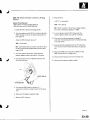
14. Checkresistancebetweenthe No. 7 and the No. 16
t e r m i n a l sa n d b e t w e e nt h e N o . 6 a n dt h e N o . 1 5
t e r m i n a l so f S R Su n i tc o n n e c t o r A( 1 8 P )T. h e r e
should be an open circuit,or at least 1 M Q .
YES Go to step 9.
NO Short in the driver'sairbag;replacethe
driver's airbag (seepage 23-'l13).1
SRSUNITCONNECTOR
A {18P)
GRN/WHT GRN/RED
9. Turn the ignition switch OFF.Disconnectthe
batterynegativecable,and wait for 3 minutes.
10. Disconnectthe front passenger'sairbag4P
connectorfrom dashboardwire harnessB (seestep
3 o n p a g e2 3 - 2 1 ) .
1'1. Disconnectboth seat belt tensioner2P connectors
from the floor wire harness(seestep 5 on page 23-
GRN/YEL
GRN/BLK
Wire side of femaleterminals
22t.
ls the rcsistance as specified?
1 2 . D i s c o n n e cSt R Su n i tc o n n e c t o r A( 1 8 P ) f r o mt h e
SRS unit (seestep 7 on page 23-221.
YES FaultySRS unit; replacethe SRS unit (see
page 23-122],.a
13. Disconnectthespecialtool from the cable reel.
NO Go to step 15.
Disconnectthe cable reelfrom dashboardwire
harnessB. Checkresistancebetweenthe No,7 and
the No. 16 terminalsand betweenthe No. 6 and the
No. 15 terminalsof SRS unit connectorA (18P).
Thereshould be an open circuit,or at least 1 M Q .
ls the resistance as specified?
YES Replacethe cable reel.I
N O - R e p l a c ed a s h b o a r dw i r e h a r n e s sB . l
IJ
23-38
DTC1-4:Shortto Powerin Driver'sAirbag
Inflator
Readthe DTC.
ls DTC 1-4indicated?
SpecialToolsBequired
. sRS inflatorsimulator07SAZ-T84011A
. SRSsimulatorlead F 07XAZ-S230100
1. Erasethe DTCmemory (seepage 23-26).
2 . T u r nt h e i g n i t i o ns w i t c hO N ( l l ) ,a n d c h e c kt h a tt h e
SRS indicatorcomes on for about 6 secondsand
then goes off.
YES-Go to step 9.
NO-Short to power in the driver's airbag;replace
t h e d r i v e r ' sa i r b a g( s e ep a g e2 3 - 11 3 ) . 1
te
9 . T u r nt h e i g n i t i o ns w i t c hO F F .D i s c o n n e ct h
batterynegativecable,and wait for 3 minutes.
1 0 .Disconnectthe front passenger'sairbag4P
connectorfrom dashboardwire harnessB (seestep
3 o n p a g e2 3 ' 2 1 ) .
Does the SRS indicator stay on?
YES Go to step 3.
NO Intermittentfailure,system is OK at this time.
Go to TroubleshootingIntermittentFailures(see
page 23-26).
3. Turn the ignition switch OFF.Disconnectthe
batterynegativecable,and wait for 3 minutes.
s
1 1 .Disconnectboth seat belt tensioner2P connectors
from the floor wire harness(seestep 5 on page 23221.
1 2 . D i s c o n n e cSt R Su n i tc o n n e c t oA
r ( 1 8 P ) f r o mt h e
(see
page
23-22).
step 7 on
SRSunit
Disconnectthe specialtool from the cable reel.
4. Disconnectthe driver'sairbag4P connector(A)
f r o m t h e c a b l er e e l .
't4. Reconnectthe batterynegativecable.
07sAz-T84011A
C o n n e ctth e S R Si n f l a t o rs i m u l a t o r( 2 0
connectors)and the simulatorlead F to the cable
reel.
6 . Reconnectthe batterynegativecable.
1 . Erasethe DTCmemory.
(cont'd)
23-39
SRS
L
DTCTroubleshooting(cont'd)
Turn the ignition switch ON {ll).
1 6 . Checkfor voltage betweenthe No. 7 terminal of
) n d b o d y g r o u n d ,t h e
S R Su n i tc o n n e c t oA
r ( 1 8 Pa
N o . 1 6t e r m i n a a
l n d b o d y g r o u n d ,t h e N o . 6
t e r m i n a la n d b o d y g r o u n d ,a n dt h e N o . 1 5t e r m i n a l
and body ground.Thereshould be 0.5 V or less.
DTC1-5:Shortto Groundin Driver's
Airbag
lnflator
Special Tools Required
. SRS inflatorsimulator07SM-TB4011A
. SRSsimulatorlead F 07XM-S230100
1. Erasethe DTCmemory (seepage 23-26).
SRSUNITCONNECTOR
A {18P)
2. Turn the ignition switch ON (ll),and checkthatthe
SRS indicatorcomes on for about 6 secondsand
then goes oIf.
Does the SBS indicator stay on?
YES Go to step 3.
Wiresideol lemaleterminals
NO-lntermittent failure,system is OK at this time.
Go to TroubleshootingIntermittentFailures(see
page 23-26).
Is the voltage as specilied?
3. Turn the ignition switch OFF.Disconnectthe
batterynegativecable,and wait for 3 minutes.
YES-Faulty SRS uniUreplacethe SRS unit (see
page 23-122).a
4. Disconnectthe driver'sairbag 4P connector(A)
from the cable reel.
a
NO Go to step 17.
1 1 . Turn the ignition switch OFF.
1 8 . Disconnectthe cable reel from dashboardwire
harnessB.
1 9 . Turn the ignition switch ON (ll).
07sAz-T84011A
20. Checkfor voltage betweenthe No. 7 terminal of
) n d b o d y g r o u n d ,t h e
r ( 1 8 Pa
S R Su n i tc o n n e c t oA
N o . 1 6t e r m i n a la n d b o d y g r o u n d ,t h e N o . 6
t e r m i n a la n d b o d y g r o u n d ,a n d t h e N o . 1 5t e r m i n a l
and body ground.Thereshould be 0.5 V or less.
ls the voltage as specitied?
07xaz-s230100
C o n n e ctth e S R Si n f l a t o rs i m u l a t o r( 2 0
connectors)and the simulatorlead F to the cable
reet.
YES Replace
t h e c a b l er e e l . l
Reconnectthe batterynegativecable.
N O - R e p l a c ed a s h b o a r dw i r e h a r n e s sB . l
1 . Erasethe DTCmemory.
IJ
23-40
8. Readthe DTC.
ls DTC 1-5 indicated?
YES-Go to step 9.
NO Short to ground in the driver's airbaginflator;
replacethe driver's airbag(seepage 23-113).I
9. Turn the ignition switch OFF.Disconnectthe
batterynegativecable,and wait for 3 minutes.
14. Checkresistancebetweenthe No.7 terminal of
SRS unit connectorA {18P)and body ground,the
N o . 1 6t e r m i n a la n d b o d y g r o u n d ,t h e N o . 6
t e r m i n a la n d b o d y g r o u n d .a n d t h e N o . 1 5t e r m i n a l
and body ground.There should be an open circuit,
o r a t l e a s t1 M Q .
A I18PI
SRSUNITCONNECTOR
GRN/WHT
GRN/RED
'10.
Disconnectthefront passenger'sairbag 4P
connectorfrom dashboardwire harnessB (seestep
2 on page 23-21).
11. Disconnectboth seat belt tensioner2P connectors
from the floor wire harness (seestep 5 on page 23-
22t.
12. DisconnectSRSunit connectorA (18P)fromthe
SRS unit (see step 7 on page 23-22],.
1 3 . D i s c o n n e c t t hsep e c i a l t o o l f r o mt h e c a b l er e e l .
Wiresideof femaleterminals
ls the resistance as specified?
YES-Faulty SRS unit; replacethe SRS unit {see
page 23-1221.f
N O - G o t o s t e p1 5 .
Disconnectthe cable reel from dashboardwire
h a r n e s sB .
1 6 . Checkresistancebetweenthe No.7 terminal of
S R Su n i tc o n n e c t oA
r ( 1 8 P )a n d b o d y g r o u n d ,t h e
N o . 1 6t e r m i n a a
l n d b o d y g r o u n d .t h e N o , 6
terminaa
l n d b o d y g r o u n d ,a n dt h e N o . 1 5t e r m i n a l
a n d b o d y g r o u n d .T h e r es h o u l db e a n o p e nc i r c u i t ,
or at least 1 fvlQ .
ls the resistanceas specified?
t h e c a b l er e e l . I
YES Replace
NO Replacedashboardwire harnessB.l
23-41
sRs
DTCTroubleshooting(cont'dl
DTC2-1:Openin FrontPassenger's
Airbag
Inflator
DfC 2-2:Increased
Resistance
in Front
Passenger's
AirbagInflator
{
Readthe DTC.
ls DTC 2-1 or DTC 2-2 indicated?
YES Go to step 9.
Special Tools Bequired
. S R Si n f l a t o rs i m u l a t o 0
r 7SAZ-T84011A
. SRSsimulatorlead F 07XAZ-S230100
'1.
NO-Open or increasedresistancein the front
passenger'sairbag inflator;replacethe front
p a s s e n g e r 'asi r b a g{ s e ep a g e2 3 - 1 1 4 ) . I
Erasethe DTCmemory {seepage 23-26).
9 . Turn the ignitionswitch OFF.Disconnectthe
2 . T u r nt h e i g n i t i o ns w i t c hO N ( l l ) ,a n d c h e c kt h a t t h e
SRS indicatorcomes on for about 6 secondsand
then goes off.
batterynegativecable,and wait for 3 minutes.
1 0 .Disconnectthe driver'sairbag 4Pconnectorfrom
the cable reel (seestep 2 on page 23-21],.
Does the SRS indicator stay on?
1 1 .Disconnectboth seatbelt tensioner2P connectors
from the floor wire harness(seestep 5 on page 2322).
YES Go to step 3.
NO Intermittentfailure,system is OK at this time,
Go to TroubleshootingIntermittentFailures(see
page 23-261.
3. Turn lhe ignition switch OFF.Disconnectthe
batterynegativecable,and wait for 3 minutes.
DisconnectSRS unit connectorA (18P)from the
SRSunit (seestep 7 on page23-22).Do not
disconnectthe specialtool from dashboardwire
h a r n e s sB .
!.
4. Disconnectthe front passenger'sairbag 4P
connector(A) from dashboardwire harnessB.
07sAz-T84011A
07xAz-s230100
5 . Connectthe SRS inflatorsimulator(2 0
connectors)and the simulatorlead F to dashboard
w i r e h a r n e s sB .
6 . Reconnectthe batterynegativecable.
7 . Erasethe DTCmemory.
! J
23-42
\
13. Checkresistancebetweenthe No. 4 and No. 13
t e r m i n a l sa n d b e t w e e nt h e N o . 5 a n d N o . 1 4
t e r m i n a l so f S R Su n i tc o n n e c t oA
r ( 1 8 P )T. h e r e
s h o u l db e 2 . 0 3 . 0 Q .
A {18P)
SRSUNITCONNECTOR
DTC2-3:Shortto AnotherWire or Decreased
Airbag
Resistance
in FrontPassenger's
lnJlator
SpecialToolsRequired
. S R Si n f l a t o rs i m u l a t o 0
r 7SAZ-T8401'1A
. SRSsimulatorlead F 07XAZ-S230100
1. Erasethe DTCmemory (seepage 23-261.
2 . T u r nt h e i g n i t i o ns w i t c hO N ( l l ) , a n d c h e c k t h a t t h e
SRS indicatorcomes on for about 6 secondsand
then goes off.
Does the SRS indicator stay on?
Wiresideof femaleterminals
ls the resistance as specified?
J
YES FaultySRSunit or poor contactat SRS unit
connectorA (18P).Checkthe connection;if the
connectionis OK, replacethe SRSunit (seepage
23-1221.a
NO Open or increasedresistancein dashboard
wire harnessB; replacedashboardwire
h a r n e s sB . I
YES-Go to step 3.
NO Intermittentfailure, system is OK at this time.
Go to TroubleshootingIntermittentFailures{see
page23-26).
3. Turn the ignition switch OFF.Disconnectthe
batterynegativecable,and wait for 3 minutes.
4. Disconnectthe front passenger'sairbag 4P
connector(A) from dashboardwire harnessB.
07sAz-T84011A
07xAz-s230100
C o n n e ctth e S R Sl n f l a t o rs i m u l a t o r( 2 0
c o n n e c t o r sa)n d t h e s i m u l a t o rl e a dF t o d a s h b o a r d
w i r e h a r n e s sB .
6 . Reconnectthe batterynegativecable.
7 . Erasethe DTCmemory.
T J
(cont'd)
23-43
sRs
qJ
DTGTroubleshooting(cont'd)
Readthe DTC.
'12.
DisconnectSRS unit connectorA (18P)from the
SRS u nit (see step 7 on page 23-22l..
ls DTC 2-3 indicated?
YES Go to step9.
NO-Short in the front passenger'sairbag inflator;
replacethe front passenger'sairbag (seepage 231 1 4 )t .
9 . Turn the ignition switch OFF.Disconnectthe
batterynegativecable,and wait for 3 minutes.
1 0 .Disconnectthe driver'sairbag 4P connectorfrom
13. Disconnectthespecialtool from dashboardwire
h a r n e s sB .
14. Checkresistancebetweenthe No. 4 and No. 13
t e r m i n a l sa n d b e t w e e nt h e N o . 5 a n d N o . 1 4
t e r m i n a l so f S R Su n i tc o n n e c t oA
r ( 1 8 P )T. h e r e
s h o u l db e a n o p e nc i r c u i t o
, r a t l e a s t1 M Q .
SRSUNIT CONNECTOR
A I18P)
BLU/RED
the cable reel {seestep 2 on page 23-21).
1 1 .Disconnectboth seat belt tensioner2P connectors
from the floor wire harness(seestep 5 on page 23221.
BLU/BLK
Wiresideof femaleterminals
ls the resistance as specitied?
YES FaultySRSunit; replacethe SRS unit (see
page 23-122)'.a
N O - S h o n i n d a s h b o a r dw i r e h a r n e s sB ; r e p l a c e
d a s h b o a r dw i r e h a r n e s sB . l
T J
23-44
DTC2-4:Shortto Powerin FrontPassenger's
AirbagInflator
8. Readthe DTC.
ls DTC 2-4 indicated?
Special Tools Required
. SRSinflatorsimulator07SAZ-TB4011A
. SRSsimulatorlead F 07XAZ-S230100
1. Erasethe DTCmemory (seepage 23-26).
2. Turn the ignition switch ON (ll),and checkthat the
SRSindicatorcomes on for about 6 secondsand
then goes off,
Does the SRS indicatot stay on?
YES-Go to step 9.
NO-Short to power in the front passenger'sairbag
inflator;replacethe front passenger'sairbag (see
p a g e2 3 - 1 1 4 ) . I
9. Turn the ignitionswitch OFF.Disconnectthe
batterynegativecable,and wait for 3 minutes.
10. Disconnectthe driver's airbag4P connectorfrom
the cable reel (seestep 2 on page 23-21).
YES-Go to step 3.
NO Intermittentfailure,system is OK at this time.
Go to TroubleshootinglntermittentFailures(see
page23-26).
11. Disconnectboth seatbelttensioner2P connectors
from the floor wire harness(seestep 5 on page 2322).
3. Turn the ignitionswitch OFF.Disconnectthe
batterynegativecable,and wait for 3 minutes.
I
I
4. Disconnectthe front passenger'sairbag 4P
connector(A) from dashboardwire harnessB.
07sAz-T84011A
07xAz-s230100
Connectthe SRSinflatorsimulator(2 Q
connectors)and the simulatorlead F to dashboard
w i r e h a r n e s sB .
6 . Reconnectthe batterynegativecable.
7 . Erasethe DTc memory.
{cont'd)
23-45
sRs
DTCTroubleshooting(cont'd)
DisconnectSRSunit connectorA (18P)from the
SRSunit (seestep 7 on page23-221.
1 3 .Disconnectthe specialtool from dashboardwire
harnessB.
{
DTC2-5:Shortto Groundin FrontPassenger's
AirbagInflator
SpecialToolsRequired
. SRSinflator simulator07SAZ-T84011A
. SRSsimulatorlead F 07XAZ-S230100
1 4 . Reconnectthe batterynegativecable.
1. Erasethe DTCmemory (seepage 23-26).
1 5 . Turn the ignition switch ON (ll).
t o . Checkfor voltage betweenthe No. 4 terminal of
SRSunit connectorA (18P)and body ground,the
N o . 1 3t e r m i n a a
l n d b o d y g r o u n d ,t h e N o . 5
terminal and body ground,and the No. 14 terminal
and body ground.Thereshould be 0.5 V or less.
2. Turn the ignition switchON (ll),and checkthat the
SRSindicatorcomes on for about 6 secondsand
then goes off.
Does the SRS indicator stay on?
YES Go to step 3.
SRS UNIT CONNECTOBA {18PI
NO Intermittentfailure,system is OK at this time.
Go to TroubleshootingIntermittentFailures{see
page 23-261.
3. Turn the ignition switch OFF.Disconnectthe
batterynegativecable,and wait for 3 minutes.
4, Disconnectthe front passenger'sairbag4P
connector(A) from dashboardwire harnessB.
4
Wire side o{ {emaleterminals
ls the voltageas specified?
YES FaultySRSuniureplace
the SRSunit(see
page23-1221
.a
NO-Short to powerin dashboard
wire harnessB;
replacedashboard
wire harnessB.!
07saz-T84011A
07xAz-s230100
5 . Connectthe SRSinflatorsimulator(2 Q
connectors)and the simulatorlead F to dashboard
wire harnessB.
\ J
23-46
I
Reconnectthe batterynegativecable.
12. DisconnectSRS unit connectorA (18P)from the
SRS unit (seestep7 on page 23-221.
7 . Erasethe DTCmemory.
1 3 .Disconnectthespecialtool from dashboardwire
Readthe DTC.
ls DTC 2-5 indicated?
YES-Go to step 9.
NO-Shon to ground in the front passenger's
airbaginflator;replacethe front passenger'sairbag
( s e ep a g e2 3 - 11 4 ) . 1
9 . Turn the ignitionswitch OFF.Disconnectthe
batterynegativecable,and wait for 3 minutes.
h a r n e s sB .
't4.
Checkresistancebetweenthe No. 4 terminal of
SRS unit connectorA (18P)and body ground,the
No. 13 terminal and body ground.the No. 5
terminaa
l n d b o d y g r o u n d ,a n d t h e N o . 1 4t e r m i n a l
and body ground.Thereshould be an open circuit,
o r a t l e a s tl M Q .
A {18P}
SRSUNITCONNECTOR
BLU/RED
BLU/YEL
1 0 .Disconnectthe driver's airbag4P connectorfrom
the cable reel {seestep 2 on page 23-21).
1 1 .Disconnectboth seat belt tensioner2P connectors
from the floor wire harness(seestep 5 on page 2322).
I
I
Wire side ol temaleterminals
ls the tesistanceas specitied?
YES FaultySRSuniureplacethe SRSunit(see
page23-122),
.l
wire harnessB;
NO Shortto groundin dashboard
r e p l a cdea s h b o a rwdi r eh a r n e sBs . l
I
23-47
sRs
DTCTroubleshooting(cont'dl
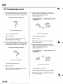
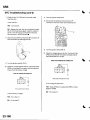
DTC3-1:Openin Driver'sSeatBeltTensioner
DTC3-2:Increased
Resistance
in Driver's
SeatBeltTensioner
6. Reconnectthe batterynegativecable.
Special Tools Required
. sRS inflatorsimulator07sAz-TB4011A
. SRSsimulatorlead C 07TM-S25011A
. SRSsimulatorlead F 07XAZ-S230100
8. Readthe DTC.
7. Erasethe DTCmemory.
ls DTC 3-1ot DTC 3-2 indicated?
YES Go to step 9.
1. Erasethe DTCmemory (seepage 23-26).
NO-Open or increasedresistancein the driver's
seat belt tensioner;replacethe driver'sseat belt
(seepage23-4).I
2. Turn the ignition switch ON (ll),and checkthat the
SRSindicatorcomes on for about 6 secondsand
then goes off.
L Turn the ignition switch OFF.Disconnectthe
batterynegativecable,and wait Ior 3 minutes.
Does the SRS indicator stay on?
YES Go to step 3.
10. Disconnectthe floor wire harness4P connector
C403{A)from dashboardwire harnessB.
NO Intermittentfailure,system is OK at this time.
Go to TroubleshootinglntermittentFailures(see
page 23-26).
3. Turn the ignition switch OFF.Disconnectthe
batterynegativecable,and wait for 3 minutes.
4. Disconnectthe driver's seat belt tensioner2P
connector{A) trom the floor wire harness.
07sAz-T84011A
07sAz-T8401'lA
1 1 .Connectthe SRSinflatorsimulator(2 Q
connectors)and simulatorlead F to dashboardwire
harnessB.
1 2 . Reconnectthe batterynegativecable.
Erasethe DTCmemory.
07TAZ-52501'lA
1 4 .Readthe DTC.
5. ConnecttheSRSinflatorsimulator(2 0 connector)
and simulatorlead C to the floor wire harness.
ls DTC 3-1 or DTC 3-2 indicated?
YES Go to step 15.
NO-Open or increased
r e s i s t a n c ien t h e f l o o rw i r e
harness;replacethe floor wire harness.l
t5.
23-48
Turn the ignition switch OFF.Disconnectthe
batterynegativecable.and wait for 3 minutes.
\ J
I
to.
Oisconnectthe driver's airbagconnector(seestep
2 on page 23-21),f ront passenger'sairbag
connector(seestep 3 on page 23-21),andfront
passenger'sseat belt tensionerconnector(seestep
5 on page 23-22).
1 7 . DisconnectSRSunit connectorA (18P)from the
SRSunit (seestep 7 on page 23-22).Do not
disconnectthe specialtool from dashboardwire
harnessB.
1 8 . Checkresistancebetweenthe No.8 terminal and
r (18P).
t h e N o . 1 7t e r m i n a o
l f S R Su n i tc o n n e c t oA
2
.
0
3
.
0
T h e r es h o u l db e
Q.
DTC3-3:Shortto AnotherWire or Decreased
in Driver'sSeatBeltTensioner
Resistance
SpecialToolsRequired
. SRS inflatorsimulator07SAZ-T8401'1A
. SRSsimulatorlead C 07TM-S25011A
. SRSsimulatorlead F 07XAZ-S230100
1. Erasethe DTCmemory (seepage 23-26).
2. Turn the ignition switch ON (ll),and checkthatthe
SRS indicatorcomes on for about 6 secondsand
then goes off.
Does the SRS indicator stay on?
A (18P)
SRSUNITCONNECTOR
RED/WHT
2
3
10 1 l 1Z t 3
5
6
1
t 5 16
i-4
\lel a;
E a
RED/BLU
I
]
Wiresideof femaleterminals
YES Go to step 3.
NO-lntermittent failure,system is OK at this time,
Go to TroubleshootingIntermittentFailures{see
page 23-26).
Turn the ignition switch OFF.Disconnectthe
batterynegativecable,and wait for 3 minutes.
Disconnectthe driver'sseat belt tensioner2P
connector(A) from the floor wire harness.
ls the resistance as specitied?
YES FaultySRS unit or poor contactat SRSunit
connectorA (18P)and the SRSunit. Checkthe
connection;if the connectionis OK, replacethe
SRSunit (seepage 23-'1221.a
-T84011A
NO Open or increasedresistancein dashboard
wire harness
w i r e h a r n e s sB ; r e p l a c ed a s h b o a r d
B,t
07TAZ-S25011A
5 . C o n n e ctth e S R Si n f l a t o rs i m u l a t o r( 2 0 c o n n e c t o r )
a n d s i m u l a t o rl e a dC t o t h e f l o o rw i r e h a r n e s s .
I
(cont'd)
23-49
sRs
DTCTroubleshooting(cont'd)
6. Reconnectthebatterynegativecable.
7. Erasethe DTCmemory.
8. Readthe DTC.
ls DTC 3-3 indicated?
16. Disconnectthe driver'sairbagconnector(seestep
2 on page23-211,lrontpassenger'sairbag
connector(seestep 3 on page 23-21),and front
passenger'sseat belt tensionerconnector(seestep
5 on page 23-22).
1 7 . D i s c o n n e cSt R Su n i t c o n n e c t oA
r ( 1 8 P f)r o m t h e
SRSunit (seestep 7 on page 23-22:,.
YES-Go to step L
NO-Shon in the driver'sseat belt tensioner;
replacethe driver's seat belt (seepage 23-4).1
L Turn the ignition switch OFF.Disconnectthe
batterynegativecable,and wait for 3 minutes.
10. Disconnectfloor wire harness4P connectorC403
(A)from dashboardwire harnessB.
18. Disconnectthe specialtool from dashboardwire
harnessB.
1 9 . C h e c kr e s i s t a n c be e t w e e nt h e N o . 8 t e r m i n a a
l nd
t h e N o . 1 7t e r m i n a o
l f S R Su n i tc o n n e c t oA
r ('l8P).
Thereshould be an open circuit,or at least 1 l\4Q .
SRSUNIT CONNECTOR
A I18P)
RED/WHT
RED/BLU
07sAz-TB4or
1A
L
J
W i r es i d eo f f e m a l e
terminals
ls the resistanceas specified?
1 1 .ConnecttheSRSinflatorsimulator(2 Q
connectors)and simulatorlead F to dashboardwire
harnessB.
YES FaultySRS unit; replacethe SRSunit (see
page 23-1221.a
N O - S h o r ti n d a s h b o a r dw i r e h a r n e s sB ; r e p l a c e
d a s h b o a r dw i r e h a r n e s sB . l
Reconnectthe batterynegativecable.
1 3 .Erasethe DTCmemory.
1 4 .Readthe DTC.
ls DTC 3-3 indicated?
YES-Go to step 15.
NO Short in the floor wire harness;replacethe
floor wire harness.l
Turn the ignition switch OFF.Disconnectthe
batterynegativecable,and wait for 3 minutes.
t J
23-50
I
J
DTC3-4:Shortto Powerin Driver'sSeatBelt
Tensioner
6. Reconnectthe batterynegativecable.
7. Erasethe DTCmemory.
SpecialToolsBequired
. SRSlnflatorsimulator07SAZ-TB4011A
. S R Ss i m u l a t o lre a dC 0 7 T M - S 2 5 0 1 1 A
. SRSsimulatorlead F 07XAZ-S230100
8. Readthe DTC.
Is DTC 3-4 indicated?
1. Erasethe DTCmemory (seepage 23-261.
YES- Go to step 9.
2. Turn the ignition switch ON (ll),and checkthat the
SRSindicatorcomes on for about 6 secondsand
then goes off.
NO-Short to power in the driver'sseat belt
tensioner;replacethe driver'sseat belt
( s e ep a g e2 3 - 4 ) . 1
L Turn the ignition switch OFF.Disconnectthe
batterynegativecable,and wait for 3 minutes.
Does the SRS indicatot stay on?
YES- Go to step 3.
NO Intermittentfailure,system is OK at this time.
Go to TroubleshootingIntermittentFailures(see
page 23-261.
L
]
10. Disconnectfloor wire harness4P connectorC403
(A) from dashboardwire harnessB.
Turn the ignitionswitch OFF.Disconnectthe
batterynegativecable,and wait for 3 minutes.
Disconnectthe driver'sseat belt tensioner2P
connector(A)from the floorwire harness.
TB4O11A
07sAz-T84011A
1 1 .C o n n e ctth e S R Si n f l a t o rs i m u l a t o r( 2 0
connectors)and simlator lead F to dashboardwire
h a r n e s sB .
' t 2 .Reconnectthe batterynegativecable.
Erasethe DTCmemory.
5. Connectthe SRSinflatorsimulator(2 !J connector)
and simulatorlead C to the floor wire harness.
1 4 . Readthe DTC.
ls DTC 3-4 indicated?
YES-- Go to step 15.
N O - S h o n t o p o w e ri n t h e f l o o rw i r e h a r n e s s ;
r e p l a c et h e f l o o rw i r e h a r n e s s . I
I
te
T u r nt h e i g n i t i o ns w i t c hO F F .D i s c o n n e ct h
batterynegativecable,and wait for 3 minutes.
(cont'd)
23-51
sRs
DTCTroubleshooting(cont'dl
16. Disconneclthe driver'sairbagconnector(seestep
2 on page23-21l,Irontpassenger'sairbag
connector(seestep 3 on page 23-2'l),and front
passenger'sseat belt tensionerconnector(seestep
5 on page 23-221.
17. DisconnectSRSunit connectorA (l8P)from the
SRS unit (see step 7 on page 23-22).
DTC3-5:Shortto Groundin Driver'sSeatBelt
Tensioner
Special Tools Required
. sRS inflalor simularor07sAz-TB4011A
. SRSsimulatorlead C 07TAZ-S25011A
. SRSsimulatorlead F 07XAZ-S230100
1. Erasethe DTCmemory {seepage23-26).
18. Disconnectthe specialtoolfrom dashboardwire
h a r n e s sB .
19. Reconnectthe batterynegativecable.
2. Turn the ignition switch ON (ll),and checkthat the
SRS indicatorcomes on for about 6 secondsand
then goes off.
20. Turn the ignition switch ON (ll),
Does the SRS indicator stay on?
21. Checkfor voltage betweenthe No. 8 terminal of
SRSunit connectorA (18P)and body ground,and
t h e N o . 1 7t e r m i n a la n d b o d yg r o u n d .T h e r es h o u l d
be 0.5 V or less.
YES Go to step 3.
SRS UNIT CONNECTORA {18PI
NO Intermittentfailure,system is OK at this time.
Go to TroubleshootingIntermittentFailures(see
page 23-26).
3. Turn the ignitionswitch OFF.Disconnectthe
batterynegativecable,and wait for 3 minutes.
4, Disconnectthe driver'sseat belt tensioner2P
connector(A) from the floor wire harness,
ls the voltageas specified?
L
-T84011A
YES-FaultySRSunit;replace
the SRSunit{see
page23-122],
.a
wire harnessB;
NO Shorttopowerin dashboard
replacedashboard
wire harnessB.l
07TAZ-S25011A
5. Connectthe SRSinflatorsimulator(2 Q conneclor)
and simulatorlead C to the floor wire harness.
L J
23-52
t
6. Reconnectthe batterynegativecable.
7. Erasethe DTCmemory.
8. Readthe DTC.
16. Disconnectthedriver'sairbagconnector(seestep
2 on page23-211,lrontpassenger'sairbag
connector(seestep 3 on page 23-21),and front
passenger'sseat belt tensionerconnector(seestep
5 on page 23-22).
17, DisconnectSRS unit connectorA ('l8P)from the
SRS unit (seestep 7 on page 23-221.
ls DTC 3-5 indicated?
YES-Go to step 9,
NO Shortto ground in the driver'sseat belt
tensioner;replacethe driver'sseat belt
(seepage 23-4).I
9. Turn the ignition switch OFF.Disconnectthe
batterynegativecable,and wait for 3 minutes.
10. Disconnectfloor wire harness4P connectorC403
(A)from dashboardwire harnessB.
18. Disconnectthe specialtoolfrom dashboardwire
harnessB.
19. Checkresistancebetweenthe No. 8 terminal of
SRS unit connectorA (18P)and body ground, and
t h e N o . 1 7t e r m i n a a
l n d b o d y g r o u n d .T h e r es h o u l d
be an open circuit,or at least 1 M Q .
A (18P)
SRSUNIT CONNECTOR
)
07sAz-T84011A
ls the resistance as specified?
'11.
C o n n e ctth e S R Si n f l a t o rs i m u l a t o r( 2 Q
connectors)and simulatorlead F to dashboardwire
h a r n e s sB .
Y E S - F a u l t yS R Su n i u r e p l a c et h e S R Su n i t{ s e e
page 23-122l,.a
NO Short to ground in dashboardwire harnessB;
r e p l a c ed a s h b o a r dw i r e h a r n e s sB . l
Reconnectthe batterynegativecable.
Erasethe DTCmemory.
1 4 . Readthe DTC.
ls DTC 3-5 indicated?
YES Go to step 15.
NO-Short to ground in the floor wire harness;
replacethe floor wire harness.l
I
Turn the ignition switch OFF.Disconnectthe
batterynegativecable,and wait for 3 minutes.
23-53
sRs
DTCTroubleshooting{cont'd)
DTC21-1:Openor Increased
Resistance
in
Driver'sSeatBeltBuckleTensioner
8. Readthe DTC.
l s D T C 2 1 - 1i n d i c a t e d ?
SpecialTools Required
. SRSinflatorsimulator07SAZ-TB4011A
. SRSsimulatorlead F 07XAZ-S230100
1. ErasetheDTCmemory (seepage 23-261.
2. Turn the ignition switch ON (ll),and checkthat the
SRS indicatorcomes on for about 6 secondsand
then goes off.
Does the SBS indicatot stay on?
YES Go to step3.
NO-lntermittent failure,system is OK at this time.
Go to TroubleshootingIntermittentFailures(see
page 23-261.
3. Turn the ignition switch OFF.Disconnectthe
batterynegativecable,and wait for 3 minutes.
4. Disconnectthe driver's seat belt buckletensioner
4P connector(A) from the floor wire harness.
YES Go to step 9.
NO Open or increasedresistancein the driver's
seat belt buckletensioner;replacethe driver'sseat
b e l tb u c k l e . I
9. Turn the ignition switch OFF.Disconnectthe
batterynegativecable.and wait for 3 minutes.
10. Disconnectboth side airbag2P connectors(see
step 4 on page 23-2lland the front passenger's
seat belt buckletensioner4P connector(seestep 6
on page 23-22).
1 1 . D i s c o n n e cSt R Su n i tc o n n e c t o B
r ( 1 8 P ) f r o mt h e
SRSunit (seestep 7 on page 23'22).Do not
disconnectthe specialtool from the floor wire
narness.
12. Checkresistancebetweenthe No. 1 and No. 10
t e r m i n a l so f S R Su n i tc o n n e c t oB
r ( 1 8 P )T. h e r e
s h o u l db e 2 . 0- 3 . 0 O .
b
/
SRSUNITCONNECTOR
B Il8PI
GRN/YEL
l t ' '
A\ I' ?
Y
l r 0t l
]
3
6
1
6
s
1 5 t 6 17 t6
TI
GRN/BLK
W i r es i d eo f f e m a l tee r m i n a l s
5. ConnecttheSRSin{latorsimulator(2 Q connectors)
and simulatorlead F to the Iloor wire harness.
6. Reconnectthe batterynegativecable.
7. Erasethe DTCmemory.
ls the resistanceas specified?
Y E S * F a u l t yS R Su n i to r p o o rc o n t a c a
t t S R Su n i t
) n d t h e S R Su n i t .C h e c kt h e
c o n n e c t oB
r ( 1 8 Pa
connection;if the connectionis OK, replacethe
SRS unit (seepage 23-122).a
NO Open or increasedresistancein the floor wire
h a r n e s sr;e p l a c et h e f l o o rw i r e h a r n e s s . l
L J
23-54
I
DTC21-3:Shortto AnotherWireor
Decreased
Resistance
in Driver'sSeatBelt
EuckleTensioner
Special Tools Required
. SRSinflatorsimulator07SAZ-T840't1A
. SRSsimulatorlead F 07XAZ-S230100
8. Readthe DTC.
ls DTC 21-3 indicated?
YES-Go to step 9.
NO- Short in the driver'sseat belt buckle
tensioner;replacethe driver's seat belt buckle.l
1. Erasethe DTCmemory (see page23-26).
2. Turn the ignition switch ON (ll),and checkthat the
S R Si n d i c a t o cr o m e so n f o r a b o u t6 s e c o n d sa n d
then goes off.
Does the SRS indicator stay on?
9. Turn the ignition switch OFF.Disconnectthe
batterynegativecable,and wait for 3 minutes,
10. Disconnectboth side airbag2P connectors(see
step 4 on page 23-21)and the front passenger's
seat belt buckletensioner4P
connector(seeslep 6 on page 23-22).
YES Go to step 3.
NO Intermittentfailure.system is OK at this time.
Go to TroubleshootingIntermittentFailureslsee
page 23-26).
Turn the ignitionswitch OFF.Disconnectthe
batterynegativecable,and wait for 3 minutes.
I
f
D i s c o n n e ct h
t e d r i v e r ' ss e a tb e l tb u c k l et e n s i o n e r
4P connector(A) from the floor wire harness.
1 1 . D i s c o n n e c t S RuSn i t c o n n e c t o r B( 1 8 P ) f r o m t h e
SRS unit {seestep 7 on page 23-22l .
'12.
Disconnectthe specialtoolf rom the floor wire
harness.
13. Checkresistancebetweenthe No. 1 and No. 10
t e r m i n a l so f S R Su n i tc o n n e c t o B
r ( 1 8 P )T. h e r e
s h o u l db e a n o p e nc i r c u i t o
, r a t l e a s t1 M Q .
SRS UNIT CONNECTORB {18PI
GRN/YEL
GRN/BLK
Wiresideof femaleterminals
ls the resistanceas specified?
C o n n e c t t h eS R Si n f l a t o rs i m u l a t o (r 2 i )
c o n n e c t o r sa)n d s i m u l a t o rl e a dF t o t h e f l o o r
w t r en a r n e s s .
6 . Reconnectthe batterynegativecable.
YES FaultySRS unit; replacethe SRSunit (see
page 23-1221.a
NO Short in the floor wire harness;replacethe
f l o o rw i r e h a r n e s s . l
7 . Erasethe DTCmemory.
23-55
sRs
(cont'dl
DTCTroubleshootang
DTG21-4:Shortto Powerin Driver'sSeatBelt
BuckleTensioner
Readthe DTC.
ls DTC 21-4 indicated?
SpecialToolsRequired
. SRSinflatorsimulator07SAZ-TB4011A
. SRSsimulatorlead F 07XM-S230100
1. Erasethe DTCmemory (seepage23-26).
2. Turn the ignition switch ON (ll),and checkthat the
SRSindicatorcomes on for about 6 secondsand
then goes off.
YES Go to step 9.
NO Shon to power in the driver'sseat belt buckle
tensioner;replacethe driver's seatbelt buckle.l
L Turn the ignition switch OFF.Disconnectthe
batterynegativecable,and wait for 3 minutes.
1 0 .Disconnectboth side airbag2P connectors(see
Does the SRS indicatot stay on?
YES-Go to step 3.
step 4 on page 23-21)and the front passenger's
seat belt buckletensioner4P connector(seestep 6
on page 23-22).
NO Interminentfailure,system is OK at this time.
Go to TroubleshootingIntermittentFailures(see
page 23'26).
3. Turn lhe ignition switch OFF.Disconnectthe
batterynegativecable,and wait for 3 minutes.
4. Disconnectthe driver's seatbelt buckletensioner
4P connector(A) from the floor wrre narness.
t,
.J
5 . ConnecttheSRSinflatorsimulator{2 0
connectors)and the simulatorlead F to the f loor
wireharness.
Reconnectthe batterynegativecable.
7 . Erasethe DTCmemory.
\, .J
23-56
1 1 .DisconnectSRS unit connectorB (18P)from the
SRSunit (seestep 7 on page 23-22).
DTC21-5:Shortto Groundin Driver'sSeat
BeltBuckleTensioner
1 2 . Disconnectthe specialtool from the floor wire
harness.
Special Tools Required
. SRS inflatorsimulator07SAZ-TB4011A
. SRSsimulatorlead F 07XAZ-S230100
Reconnectthe batterynegativecable.
1 4 . Turn the ignitionswitch ON (ll).
Checkfor voltage betweenthe No. 1 lerminal of
SRSunit connectorB {18P)and body ground, and
t h e N o . 1 0t e r m i n a la n d b o d y g r o u n d .T h e r es h o u l d
be 0.5 V or less.
SRSUNITCONNECTOR
B I18PI
1. Erasethe DTCmemory {seepage 23-26}.
2. Turn the ignition switch ON (ll),and checkthat the
SRSindicatorcomes on for about 6 secondsand
then goes off.
Does the SBS indicator stay on?
YES-Go to step 3.
NO Intermittentfailure,system is OK at this time.
Go to TroubleshootingIntermittentFailures(see
page 23-26).
Turn the ignition switch OFF.Disconnectthe
batterynegativecable,and wait for 3 minutes.
I
f
4 . Disconnectthe driver'sseat belt buckletensioner
4P connector{A) from the floor wire harness.
J
ls the voltageas specitied?
YES FaultySRSunit;replace
the SRSunit(see
page23-1221
.f
NO Shortto powerin thefloorwire harness;
replace
the floorwire harness.l
C o n n e ctth e S R Si n f l a t o rs i m u l a t o r( 2 Q
connectors)and simulatorlead F to the floor wire
n ar n e s s .
6 . Reconnectthe batterynegativecable.
7 . Erasethe DTCmemory.
(cont'd)
23-57
sRs
DTCTroubleshooting(cont'dl
DTC4-1:Openin FrontPassenger's
SeatBelt
renstoner
DTC4-2:lncreasedResistance
in Front
Passenger's
SeatBeltTensioner
Readthe DTC.
ls DTC 21-5 indicated?
YES Go to step 9.
NO Short to ground in the driver's seat belt
buckletensioner;replacethe driver's seat belt
buckle.l
9 . Turn the ignitionswitch OFF.Disconnectthe
Special Tools Required
. SRS inflatorsimulator07SM-T84011A
. SRSsimulatorlead C 07TAZ-S25011A
. SRSsimulatorlead F 07XAZ-S230100
'L
Erasethe DTCmemory (seepage23-26).
batterynegativecable,and wait for 3 minutes.
1 0 .Disconnectboth side airbag2P connectors(see
step 4 on page 23-21)andthe front passenger's
seat belt buckletensioner4P connector(seestep 6
on page 23-221.
1 1 .DisconnectSRSunit connectorB (18P)from the
SRS unit (see step 7 on page 23-22)
1 2 .Disconnectthe specialtool from the floor wire
harness.
'1
1 3 .Checkresistancebetweenthe No. terminal of
SRS unit connectorB (18P)and body ground,and
t h e N o . 1 0t e r m i n a la n d b o d y g r o u n d .T h e r es h o u l d
b e a n o p e nc i r c u i t o
, r a t l e a s t1 M Q .
SRSUNITCONNECTOR
B {18PI
ls the tesistanceas specilied?
YES FaultySRSuniureplace
the SRSunit(see
page23-122)
.a
Turn the ignition switch ON {ll),and checkthat the
SRS indicatorcomes on for about 6 secondsand
then goes off.
Does the SBS indicator stay on?
YES-Go to step 3.
NO- Intermittentfailure,system is OK at this time.
Go to TroubleshootingIntermittentFailures{see
page23-26).
Turn the ignition switch OFF.Disconnectthe
batterynegativecable,and wait for 3 minutes.
Disconnectthe front passenger'sseat belt
tensioner2P connector(A) from the floor wire
harness.
07TAZ-525011A
5. Connectthe SRS inflatorsimulator(2 0 connector)
a n d s i m u l a t o rl e a dC t o t h e f l o o rw i r e h a r n e s s .
N O - S h o r t o g r o u n di n t h ef l o o rw i r eh a r n e s s ;
replace
thefloorwire harness.l
\ J
23-58
)
6. Reconnectthe batterynegativecable.
7. Erasethe DTCmemory.
15. Turn the ignition switch OFF.Disconnectthe
batterynegativecable.and wait for 3 minutes.
'16.
8. Readthe DTC.
ls DTC 4-1 or DTC 4-2 indicated?
Disconnectthe driver'sairbagconnector{seestep
2 on page23-211,
tront passenger'sairbag
connector(seestep 3 on page 23-21),and driver's
seat belt tensionerconnector(seestep 5 on page
23-221.
YES Go to step 9.
NO-Open or increasedresistancein the front
passenger'sseat belttensioner;replacethe front
passenger'sseat belt (seepage 23-4).t
L Turn the ignition switch OFF.Disconnectthe
batterynegativecable,and wait for 3 minutes.
10, Disconnectthe floor wire harness4P connector
C403(A)from dashboardwire harnessB.
17. DisconnectSRS unit connectorA (18P)from the
SRS unit (seestep 7 on page 23-22).Do not
disconnectthe specialtool from dashboardwire
harnessB.
18. Checkresistancebetweenthe No. 9 terminal and
'18
the No. terminal of SRS unit connectorA (18P).
T h e r es h o u l db e 2 . 0 - 3 . 0 Q .
SRS UNIT CONNECTORA {18P}
RED/YEL
1
2
3 4
1 0 11 12
7
5
15
)
8
{
l
l 6
1 7 r8l \t
r l
RED/BLK
07sAz-T840't
1A
Wire side of lemale terminals
ls the resistance as specitied?
1 1 .Connectthe SRSinflatorsimulator(2 i)
connectors)and simulatorlead F to dashboardwire
harnessB.
YES FaultySRS unit or poor contactat SRS unit
connectorA (18P)and the SRS unit. Checkthe
connection;if the connectionis OK, replacethe
SRS unit (seepage 23-122l,.a
1 2 .Reconnectthe batterynegativecable.
Erasethe DTCmemory.
NO-Open or increasedresistancein dashboard
wire harnessB; replacedashboardwire harness
B.T
1 4 . Readthe DTC.
ls DTC 4-l or DTC 4-2 indicated?
YES-Go to step
'15.
NO-Open or increasedresistancein the floor wire
harness;replacethe floor wire harness.I
I
23-59
sRs
DTCTroubleshooting(cont'dl
DTC4-3:Shortto AnotherWire or Decreased
Resistance
in FrontPassenger's
SeatBelt
Tensioner
Special Tools Required
. SRSinflatorsimulator07SAZ-TB40l1A
. SRSsimulatorlead C 07TM-S25011A
. SRSsimulatorlead F 07XAZ-S230100
8. Readthe DTC.
ls DTC 4-3 indicated?
YES-Go to stepL
NO-Short in the front passenger'sseatbelt
tensioner;replacethe front passenger'sseat belt
( s e ep a g e2 3 - 4 ) . 1
1. ErasetheDTCmemory (seepage 23-26).
2. Turn the ignitionswitch ON (ll),and checkthat the
SRSindicatorcomes on for about 6 secondsand
then goes off.
9. Turn the ignition switch OFF.Disconnectthe
batterynegativecable,and wait for 3 minutes.
'10.
Disconnectthe floor wire harness4P connector
C403{A)from dashboardwire harnessB.
Does the SRS indicator stay on?
YES-Go to step 3.
NO Intermittentfailure.system is OK at this time.
Go to TroubleshootinglntermittentFailures(see
page 23-26).
3. Turn the ignitionswitch OFF.Disconnectthe
batterynegativecable,and wait for 3 minutes.
TB40,I1A
L
4. Disconnectthe front passenger'sseat belt
tensioner2P connector(A)from the floor wire
narness.
1 1 .C onnectthe SRSinflatorsimulator(2 0
connectors)and simulatorlead F to dashboardwire
harnessB.
Reconnectthe batterynegativecable.
1 3 .Erasethe DTCmemory.
1 4 .Readthe DTC.
ls DTC 4-3 indicated?
07TAZ-S25011A
Connectthe SRS inflatorsimulator(2 Q connector)
and simulatorlead C to the floor wire harness.
6 . Reconnectthe batterynegativecable.
Y E S - G o t o s t e p1 5 .
NO Short jn the floor wire harness;replacethe
f l o o rw i r e h a r n e s s . I
1 5 .Turn the ignition switch OFF.Disconnectthe
batterynegativecable,and wait for 3 minutes.
7 . Erasethe DTCmemory.
\ J
23-60
16. Disconnectthedriver'sairbagconnector(seestep
2 on page23-211,
front passenger'sairbag
connector(seestep 3 on page 23-21),and driver,s
seat belt tensionerconnector(seestep 5 on page
23-221.
17. DisconnectSRSunit connectorA (18p)from the
SRS unit (see step 7 on page 23-22).
18. Disconnectthe specialtool from dashboardwire
harnessB.
19. Checkresistancebetweenthe No. 9 terminal and
t h e N o . 1 8t e r m i n a o
l f S R Su n i tc o n n e c t oA
r (18p).
T h e r es h o u l db e a n o p e nc i r c u i t o
, r a t l e a s t1 M e .
SRSUNITCONNECTOR
A I18P}
RED/YEL
2 3
4
10 t l 12 t 3
5
6
8
It 6]
1. Erasethe DTCmemory (seepage 23-26).
2. Turn the ignition switch ON {ll),and checkthat the
SRS indicatorcomes on for about 6 secondsand
then goes off.
Does the SRS indicator stay on?
YES Go to step 3.
NO- Intermiftentfailure.system is OK at this time.
Go to TroubleshootingIntermittentFailures(see
page 23-261.
3. Turn the ignition switch OFF.Disconnectthe
batterynegativecable,and wait for 3 minutes.
RED/BLK
4. Disconnectthefront passenger'sseat belt
tensioner2P connector(A)from the floor wire
harness.
T
]
Special Tools Required
. SRS inflatorsimulator07SAZ-T84011A
. S R Ss i m u l a t o rl e a dC 0 7 T A Z - S 2 5 0 1 1 A
. SRSsimulatorlead F 07XAZ-S230100
r8l \P
15 16 1 7
I
DTC4-4:Shortto Powerin FrontPassenger's
SeatBeltTensioner
Wire side of femaleterminals
ls the resistanceas specified?
YES-FaultySRSunit;replace
the SRSunit(see
page23-1221
.f
NO-Short in dashboard
wire harnessB;replace
d a s h b o a rwdi r eh a r n e sB
s .I
07TAZ-S2501'lA
5. Connectthe SRSinflatorsimulator(2 e connector)
and simulatorlead C to the floor wire harness.
{cont'd)
23-61
sRs
DTCTroubleshooting(cont'd)
6. Reconnectthe batterynegativecable.
1 5 .Turn the ignitionswitch OFF.Disconnectthe
batterynegativecable,and wait for 3 minutes.
7. Erasethe DTCmemory.
t o . Disconnectthe driver's airbagconnector(seestep
tront passenger'sairbag
2 on page23-211,
connector(seestep 3 on page 23-21),and drivefs
seatbelt tensionerconnector(seestep 5 on page
23-22t.
8. Readthe DTC.
ls DTC 4-4 indicated?
YES Go to step 9.
NO-Short to power in the front passenger'sseat
belt tensioner;replacethe front passenger'sseat
b e l t( s e ep a g e2 3 - 4 ) . I
9. Turn the ignition switch OFF.Disconnectthe
batterynegativecable.and wait for 3 minutes.
'10.Disconnectfloor wire harness4P connector
1 1 . DisconnectSRS unit connectorA ('l8P)trom the
SRS unit (seestep 7 on page 23-22).
1 8 . Disconnectthe specialtool from dashboardwire
h a r n e s sB .
1 9 . Reconnectthe batterynegativecable.
20. T u r nt h e i g n i t i o ns w i t c hO N ( l l ) .
C403(A)from dashboardwire harnessB.
2 1 .Checkfor voltage betweenthe No. 9 terminal of
) n d b o d y g r o u n d ,a n d
r ( 1 8 Pa
S R Su n i tc o n n e c t oA
l n d b o d y g r o u n d .T h e r es h o u l d
t h e N o . 1 8t e r m i n a a
be 0.5 V or less.
A (18PI
SRSUNITCONNECTOR
t'
J
07sAz-TB4o11A
1 1 .Connectthe SRSinflatorsimulator(2 0
connectors)and simulatorlead F to dashboardwire
h a r n e s sB .
tJ.
terminals
WiresideoJJemale
Reconnectthe batterynegativecable.
Is the voltageas specified?
Erasethe DTCmemory.
YES FaultySRSunit; replacethe SRS unit (see
page 23'1221.a
1 4 . Readthe DTC.
ls DTC 4-4 indicated?
N O S h o r t t o p o w e ri n d a s h b o a r dw i r e h a r n e s sB ;
w i r e h a r n e s sB . l
r e p l a c ed a s h b o a r d
Y E S - G o t o s t e p1 5 .
NO- Short to power in the floor wire harness;
replacethe floor wire harness.l
J
23-62
I
DTC4-5:Shortto Groundin FrontPassenger's
SeatBeltTensioner
8. Readthe DTC.
ls DTC 4-5 indicated?
Special Tools Required
. SRSinflatorsimulator07SAZ-TB40'11A
. SRSsimulatorlead C 07TAZ-S25011A
. SRSsimulatorlead F 07XAZ-S230100
1. ErasetheDTCmemory (seepage 23-26]|.
2 . T u r nt h e i g n i t i o ns w i t c hO N ( l l ) ,a n d c h e c k t h a t t h e
SRSindicatorcomes on for about 6 secondsand
then goes off.
Does the SRS indicator stay on?
YES-Go to step 9.
NO Short to ground in the front passenger'sseat
belt tensioner;replacethe front passenger'sseat
b e l t( s e ep a g e2 3 - 4 ) . I
9. Turn the ignition switch OFF.Disconnectthe
batterynegativecable,and wait for 3 minutes.
10. Disconnectthe floor wire harness4P connector
C403(Alfrom dashboardwire harnessB.
Y E S - G o t o s r e p3 .
NO-lntermittent failure,system is OK at this time.
Go to TroubleshootingIntermittentFailures(see
page 23-26l,.
3. Turn the ignition switch OFF.Disconnectthe
batterynegativecable,and wait for 3 minutes.
I
TB40t 1A
4. Disconnectthe front passenger'sseat belt
tensioner2P connector(A) from the floor wire
harness.
1 1 .Connectlhe SRS inflatorsimulator(2 e
connectors)and simulatorlead F to dashboardwire
h a r n e s sB .
1 2 . Reconnectthe batterynegativecable.
Erasethe DTCmemory.
1 4 . Readthe DTC.
07TAZ-SZ501rA
ls DTC 4-5 indicated?
YES Go to step 15.
Connectthe SRS inflatorsimulator(2 e connector)
a n d s i m u l a t o rl e a dC t o t h e f l o o rw i r e h a r n e s s .
NO-Short to ground in the floor wire harness;
r e p l a c et h e f l o o rw i r e h ar n e s s . l
Reconnectthe batterynegativecable.
7 . Erasethe DTCmemory.
Turn the ignition switch OFF.Disconnectthe
batterynegativecable,and wait for 3 minutes.
(cont'd)
23-63
sRs
DTCTroubleshooting(cont'dl
16. Disconnectthe driver's airbagconnector(seestep
2 on page 23-21),front passenger'sairbag
connector(seestep 3 on page 23-21).and driver's
seat belt tensionerconnector(seestep 5 on page
23-22).
in
Resistance
DTC22-1:Openor Increased
FrontPassenger's
SeatBeltBuckleTensioner
SpecialTools Required
. SRSinflatorsimulator07SAZ-T84011A
. SRSsimulatorlead F 07XAZ-S230100
r ( 1 8 P ) f r o mt h e
1 7 . D i s c o n n e cSt R Su n i tc o n n e c t oA
SRSunit (seestep 7 on page 23-221.
1. Erasethe DTC memory (see page 23-261.
18. Disconnectthe specialtoolfrom dashboardwire
harnessB.
2. Turn the ignition switch ON (ll),and checkthat the
SRSindicatorcomes on for about 6 secondsand
then goes otf.
19. Checkresistancebetweenthe No.9 terminal of
) n d b o d y g r o u n d ,a n d
S R Su n i tc o n n e c t oA
r ( 1 8 Pa
t h e N o . l 8 t e r m i n a la n d b o d y g r o u n d .T h e r es h o u l d
. r a t l e a s t1 M Q .
b e a n o p e nc i r c u i t o
A {18P)
SRSUNITCONNECTOR
Does the SRS indicator stay on?
YES-Go to step 3.
NO-lntermittent failure,system is OK at this time.
Go to TroubleshootingIntermittentFailures(see
page23-26).
3. Turn the ignition switch oFF. Disconnectthe
batterynegativecable,and wait for 3 minutes.
4. Disconnectthefront passenger'sseat belt buckle
tensioner4P connector(A)from the floor wire
harness.
w i r e s i d eo f l e m a l et e r m i n a l s
ls the rcsistance as specified?
Y E S F a u l t yS R Su n i Ur e p l a c et h e S R Su n i t ( s e e
page 23-1221.1
NO-Short to ground in dashboardwire harnessB;
r e p l a c ed a s h b o a r dw i r e h a r n e s sB . I
5 . C o n n e ctth e S R Si n f l a t o rs i m u l a t o r( 2 Q
connectors)and the simulatorlead F to the floor
w t r eh a r n e s s .
23-64
\,
t
6. Reconnectthe bafterynegativecable.
7. Erasethe DTCmemory.
8. Readthe DTC.
SpecialToolsRequired
. SRS inflatorsimulator07SAZ-TB4011A
. SRSsimulator lead F 07XAZ,S230100
ls DTC 22-1 indicated?
YES-Go to step 9.
'1.
NO Open or increasedresistancein the front
passenger'sseat belt buckletensioner;replacethe
front passenger'sseat belt buckle.l
2. Turn the ignition switch ON fll), and checkthat the
SRSindicatorcomes on for about 6 secondsand
then goes off.
9. Turn the ignitionswitch OFF.Disconnectthe
batterynegativecable,and wait for 3 minutes.
10. Disconnectboth side airbag2P connectors(see
step 4 on page23-21)and the driver's seat belt
buckletensioner4P connector(seestep 6 on page
23-22).
I
DTC22-3:Shortto AnotherWire or
Decreased
Resistance
in FrontPassenger's
SeatBeltBuckleTensioner
1 1 . D i s c o n n e cSt R Su n i tc o n n e c t oB
r ( 1 8 P ) f r o mt h e
SRSunit (seestep 7 on page 23-22).Do not
disconnectthe specialtool from the floor wire
harness.
1 2 . C h e c kr e s i s t a n cbee t w e e nt h e N o . 2 a n d N o . 1 1
terminalsof SRS unit connectorB ('l8P).There
s h o u l db e 2 . 0 3 . 0 0 .
Erasethe DTCmemory (seepage 23-26).
Does the SRS indicator stay on?
YES Go to step 3.
NO Intermiftentfailure,system is OK at this time.
Go to TroubleshootingIntermittentFailures(see
page 23-26),.
3. Turn the ignition switch OFF.Disconnectthe
batterynegativecable,and wait for 3 minutes.
4. Disconnectthe front passenger'sseat belt buckle
tensioner4P connector(A) from the floor wire
harness.
SRSUNITCONNECTOR
B I,I8PI
)m
3
6
7
8
9
r5 r6 1T 1 8
W i r es i d eo f f e m a l tee r m i n a l s
ls the resistance as specified?
YES FaultySRS unit or poor contactat SRS unit
) n d t h e S R Su n i r .C h e c kt h e
c o n n e c t oB
r ( 1 8 Pa
connection;if the connectionis OK, replacethe
SRSunit (seepage 23-122).a
I t
5 . C o n n e ctth e S R Si n f l a t o rs i m u l a t o (r 2 Q
connectors)and the simulatorlead F to the floor
w t r eh a r n e s s .
6. Reconnectthe batterynegativecable.
7 . E r a s et h e D T Cm e m o r y .
NO Open or increasedresistancein the floor wire
harness;replacethe floor wire harness.l
{cont'd)
23-65
sRs
DTCTroubleshooting(cont'dl
8. Readthe DTC.
DTC22-4:Shortto Powerin FrontPassenger's
SeatBeltBuckleTensioner
ls DTC 22-3 indicated?
YES Go to slep 9.
NO-Short in the front passenger'sseat belt buckle
tensioner;replacethe front passenger'sseat belt
buckle.l
9. Turn the ignition switch OFF.Disconnectthe
batterynegativecable,and wait for 3 minutes.
10. Disconnectboth side airbag2P connectors(see
s t e p4 o n p a g e2 3 - 2 1 ) a n dt h e d r i v e r ' ss e a tb e l t
buckletensioner4P connector(seestep 6 on page
23-22).
'11.
r { 1 8 P ) f r o mt h e
D i s c o n n e cSt R Su n i tc o n n e c t oB
SRS unit (seestep 7 on page23-221.
SpecialToolsRequired
. S R Si n f l a t o rs i m u l a t o 0
r 7SAZ-TB4011A
. S R Ss i m u l a t o rl e a dF 0 7 X A z5 2 3 0 1 0 0
1. Erasethe DTCmemory (seep age23-26).
2 . T u r nt h e i g n i t i o ns w i t c hO N { l l } ,a n d c h e c kt h a tt h e
S R Si n d i c a t ocr o m e so n f o r a b o u t6 s e c o n d sa n d
then goes off.
Does the SHS indicator stay on?
YES Go to step 3.
N O I n l e r m i t t e n t f a i l u r e , s y s t ei smO K a t t h i s t i m e .
Go to TroubleshootingIntermittentFailures(see
page 23-261.
12. Disconnectthe specialtool from the floor wire
ha r n e s s .
3. Turn the ignition switch OFF.Disconnectthe
batterynegativecable,and wait for 3 minutes.
1 3 . C h e c kr e s i s t a n cbee t w e e nt h e N o . 2 a n d N o . 1 1
terminalsof SRS unit connectorB ( 18P).There
'l
should be an open circuit,or at least M !) .
4. Disconnectthe front passenger'sseat belt buckle
tensioner4P connector(A) from the floor wire
narness.
u
B {18P}
SRSUNIT CONNECTOR
GRN/RED
GRN
WiresideoI femaleterminals
ls the resistanceas specified?
YES FaultySRSunit; replacethe SRS unit (see
page 23'1221.a
5 . C o n n e ctth e S R Si n f l a t o rs i m u l a t o r( 2 ! J
connectors)and simulatorlead F to the floor wire
h ar n e s s .
NO Short in the floor wire harness;replacethe
f l o o rw i r e h a r n e s s . I
\ J
23-66
t
6. Reconnectthe batterynegativecable.
1 0 .Disconnectboth side airbag2P connectors(see
s t e p4 o n p a g e2 3 - 2 1 ) a n dt h e d r i v e r ' ss e a tb e l t
buckletensioner4P connector(seestep 6 on page
,1_r'>\
7. Erasethe DTCmemory.
8. Readthe DTC.
ls DTC 22-4 indicated?
1 1 .DisconnectSRS unit connectorB (18P)from the
SRS unit (seestep 7 on page 23-221.
YES Go to step g.
' t 2 .Disconnect
the specialtool from the floor wire
harness.
NO-Short to power in the front passenger,sseat
belt buckletensioner;replacethe front passenger,s
seat belt buckle.!
9. Turn the ignition switch OFF.Disconnectthe
batterynegativecable,and wait for 3 minutes,
t5.
Reconnectthe batterynegativecable.
1 4 . Turn the ignition switch ON (ll).
Checkfor voltage betweenthe No. 2 terminal of
S R Su n i tc o n n e c t oB
r { 1 8 P )a n d b o d y g r o u n d ,a n d
t h e N o . 1 1t e r m i n a la n d b o d y g r o u n d .T h e r es h o u l d
b e 0 . 5V o r I e s s .
SRSUNITCONNECTOR
B I18P)
ls the voltageas specified?
Y E S - F a u l t yS R Su n i t ;r e p l a c et h e S R Su n i t ( s e e
page 23-1221.l
NO Short to power in the floor wire harness;
replacethe floor wire harness.l
23-67
sRs
DTCTroubleshooting(cont'dl
DTC22-5:Shortto Groundin Front
SeatBeltBuckleTensioner
Passenger's
8. Readthe DTC.
ls DTC 22-5 indicated?
SpecialTools Required
. SRSinflatorsimulator07SAZ-T84011A
. SRSsimulatorlead F 07XAZ-S230100
1. Erasethe DTCmemory (seepage 23-26).
2. Turn the ignition switch ON (ll),and checkthat the
SRSindicatorcomes on for about 6 secondsand
then goes off.
Does the SRS indicator stay on?
YES-Go to step 3.
NO - Intermittentfailure,system is OK at this time.
Go to TroubleshootingIntermittentFailures(see
page 23-26).
YES-Go to step 9.
NO Short to ground in the front passenger'sseat
belt buckletensioner;replacethe front passenger's
s e a tb e l tb u c k l e . l
9. Turn the ignition switch OFF.Disconnectthe
batterynegativecable,and wait for 3 minutes.
10. Disconnectboth side airbag2P connectors(see
step 4 on page 23-21)and the driver'sseat belt
buckletensioner4P connector(seestep 6 on page
23-22t.
r ( 1 8 P l f r o mt h e
1 1 . D i s c o n n e cSt R Su n i tc o n n e c t oB
(see
page
7
23-221.
step on
SRS unit
3. Turn the ignition switch OFF.Disconnectthe
batterynegativecable,and wait for 3 minutes.
12. Disconnectthe specialtool from the floor wire
harness,
4. Disconnectthefront passenger'sseat belt buckle
tensioner4P connector(A)from the floor wire
harness,
13. Checkresistancebetweenthe No. 2 terminal of
SRSunit connectorB (18P)and body ground, and
the No, 11 terminal and body ground.Thereshould
be an open circuit,or at least 1 M Q.
b U
g {18PI
SRSUNITCONNECTOR
Wire side of femaleterminals
5 . Connectthe SRSinflatorsimulator(2 Q
connectors)and simulatorlead F to the floor wire
narness.
6 . Reconnectthe batterynegativecable.
1 . Erasethe DTCmemory.
ls the resistance as specified?
YES-Faulty SRSunit; replacethe SRS unit (see
page 23-1221.a
NO Short to ground in the floor wire harness;
replacethe floor wire harness.l
!U
23-68
I
DTCs-1,5-2,5-4,s-8,6-3,6-4,6-7,6-8,7-1,
7-2,7-3,A-1,4-2,8-3,8-4,8-5,8-6,9-1,9-2:
Internal
Failureof the SRSUnit
DTC10-1,10-2,10-3,10-4,10-s,10-6,10-7:
Airbags,SideAirbags,and/orSeatBeltand
Deployed
SeatBeltBuckleTensioners
NOTE:Beforetroubleshootingany of these DTCs,check
the battery/systemvoltage.lf the voltage is low, repair
the chargingsystem or replacethe batterybefore
troubleshootingthe SRS.lf the battery/systemvoltage
is now OK, ask the customerif the batteryever went
oeao,
The SRS unit must be replacedafter any airbagsand/or
tensionershave deployed(seepage 23-122).!
1. Erasethe DTCmemory (seepage 23-26).
2. Turn the ignitionswitch ON (ll),and checkthat the
SRSindicatorcomes on for about 6 secondsand
then goes off.
Does the SRS indicatot stay on?
YES Replace
t h e S R Su n i t ( s e ep a g e2 3 - 1 2 2 ) . 1
NO Intermittentfailure,system is OK at this time.
Go to TroubleshootinglntermittentFailures(see
page23-26).
l
I
23-69
SRS
DTCTroubleshooting(cont'd)
DTC13-1,13-2:InternalFailureof the Driver's
SidelmpactSensor
DTC14-1,14-2:InternalFailureofthe Front
Passenger's
SidelmpactSensor
1. Erasethe DTCmemory (seepage 23-26).
1. Erasethe DTCmemory (seepage23-26).
2. Turn the ignition switch ON (ll),and checkthat the
SRSindicatorcomes on for about 6 secondsand
then goes off.
2. Turn the ignition switch ON (ll),and checkthat the
SRSindicatorcomes on for about 6 secondsand
then goes off.
Does the SRS indicatot stay on?
Does the SRS indicator stay on?
YES Replacethe driver's side impact sensor(see
page 23-123).a
YES-Replace the front passenger'sside impact
sensor (see page 23-123],.1
NO Intermittentfailure,system is OK at this time.
Go to TroubleshootingIntermittentFailures(see
page 23-261.
NO-lntermittent failure,system is OK at this time.
Go to TroubleshootingIntermittentFailures(see
page 23-26).
U
I J
23-70
I
DTC9-3:Faulty Driver'sSeatBeltBuckle
Switch
1. Erasethe DTCmemory (seepage 23 26).
2 . T u r nt h e i g n i t i o ns w i t c hO N ( l l ) ,t h e n b u c k l ea n d
u n b u c k l et h e d r i v e r ' ss e a tb e l ts e v e r atl i m e s .
3. Readthe DTC.
ls DTC 9-3 indicated?
6. Bucklethe driver's seat belt.
Checkresistancebetweenthe No. 1 and No.3
terminalsofthe driver's seat belt buckleswitch 3P
c o n n e c l o rT. h e r es h o u l db e 0 1 ( J .
Checkresistancebetweenthe No. 1 and No.2
terminalsof the same connector.Thereshould be
a n o p e nc i r c u i t o
, r a t l e a s t1 M Q .
DRIVER'S
SEATBELTBUCKLE
SWITCH
3PCONNECTOR
YES Go to step 4.
NO Intermittentfailure,system is OK at this time.
Go to TroubleshootingIntermittentFailures(see
page 23-261.
4 . Turn the ignition switch OFF.
BLU/RED
T e r m i n asl i d eo f m a l et e r m i n a l s
5 . Disconnectthe driver's seat belt buckleswitch 3P
connector(A)from the floor wire harness.
t
T e r m i n as li d eo f m a l et e r m i n a l s
Ate the resistancereadings as specified?
YES- Go to step 7.
NO Replacethe driver'sseat belt buckleassembly,
t h e n c l e a rt h e D T C . I
I
(cont'd)
23-71
sRs
(cont'dl
DTCTroubleshooting
7, Unbucklethe driver'sseat belt.
Checkresistancebetweenthe No. 1 and No.2
terminalsofthe driver'sseat belt buckleswitch 3P
c o n n e c t o rT. h e r es h o u l db e 0 1 Q .
8. Checkresistancebetweenthe No. 1 terminal ofthe
floor wire harness3P connectorand bodv oround.
'1
T h e r es h o u l db e 0
0.
FLOORWIREHARNESS3P CONNECTOR
Checkresistancebetweenthe No. 1 and No. 3
terminalsof the same connector.There should be
an open circuit,or at least 1 M Q
DRIVER'S
SEATBELT
BUCKLE
SWITCH3PCONNECTOR
Wiresideof femaleterminals
T e r m i n asl i d eo f m a l et e r m i n a l s
BLU/RED
T e r m i n as li d eo I m a l et e r m i n a l s
ls the resistanceas specified?
YES Go to step 9.
N O O p e ni n t h e f l o o rw i r e h a r n e s so r p o o r g r o u n d
connection
a t G 5 5 1 .l f G 5 5 ' 1i s O K , r e p l a c et h e f l o o r
w r r eh a r n e s s . l
ls the rcsistance as specified?
9 . Disconnectthe negativecablefrom the battery.
YES Go to step 8.
NO-Replace the driver'sseat belt buckleassembly,
then clearthe DTC.I
1 0 . DisconnectSRS unit connectorC (8P)from the SRS
unit {seestep 7 on page 23-22).
\ J
23-72
I
11. Checkresistancebetweenthe No. 2 terminal of the
floor wire harness3P connectorand body ground.
Thereshould be an open circuit.or at least 1 fvlQ ,
13. Checkresistancebetweenthe No. 8 terminal of
SRS unit connectorC (8P)and the No. 3 terminal of
the floor wire harness3P connector.There should
be0 1Q.
FLOORWIRE HARNESS3P CONNECTOR
FLOORWIRE
HARNESS SRSUNITCONNECTORC
I8P}
3PCONNECTOB
Wiresideot temaleterminals
]
g
3
Wire side of femaleterminals
ls the resistance as specified?
ls the resistance as specitied?
Y E S - G o t o s t e p1 2 .
YES Go to step 14.
NO Short to ground in the floor wire harnessor
multiplexcontrol unit. Replacethe faulty harnessor
part.I
NO Open in the floor wire harness;replacethe
floor wire harness.l
1 2 .Checkresistancebetweenthe No. 3 terminal of the
floor wire harness3P connectorand body ground.
T h e r es h o u l db e a n o p e nc i r c u i to, r a t l e a s t1 M Q .
FLOORWIREHARNESS3P CONNECTOR
1 4 . Checkresistancebetweenthe No. 4 terminal of
l f
S R Su n i tc o n n e c t oC
r ( 8 P )a n d t h e N o . 2 t e r m i n a o
floor
wire
harness
the
3P connector.There should
be0-1 0.
FLOORWIREHARNESS
3P CONNECTOR
SRSUNITCONNECTOR
C IsPI
LT GRN
Wire side of femaleterminals
Wiresideof femaleterminals
ls the resistanceas specified?
ls the resistance as specified?
YES Replace
t h e S R Su n i t ( s e ep a g e2 3 - 1 2 2 ) . 1
YES Go to step 13.
N O - S h o r t t o g r o u n di n t h e f l o o rw i r e harness;
replacethe floor wire harness.I
N O O p e ni n t h e f l o o rw i r e h a r n e s so r m u l t i p l e x
control unit, or poor connectionat the floor wire
harness,the under-dashfuse/relaybox, and the
multiplexcontrol unit. Checkthe connectionat the
floor wire harness,the under-dashfuse/relaybox,
and the multiplexcontrol unit. lf the connectionis
OK, replacethe faulty harnessor part.l
23-73
SRS
J
DTCTroubleshooting(cont'dl
DTC9-4:FaultyFrontPassenger's
SeatBelt
BuckleSwitch
1. Erasethe DTCmemory {seepage 23-26).
2 . T u r nt h e i g n i t i o ns w i t c hO N { l l ) ,t h e n b u c k l ea n d
unbucklethe front passenger'sseat belt several
times.
3. Readthe DTC.
ls DTC 9-4 indicated?
6. Bucklethe front passenger'sseat belt.
Checkresistancebetweenthe No. 1 and No.3
terminalsof the front passenger'sseat belt buckle
switch 3P connector.Thereshould be 0- 1 Q.
Checkresistancebetweenthe No. 1 and No.2
terminalsof the same connector.Thereshould be
a n o o e nc i r c u i t o
, r a t l e a s t1 M Q .
FRONT
PASSENGER'S
SEATBELT
BUCKLE
SWITCH
3PCONNECTOR
BLU/RED
YES-Go to step 4.
NO Intermittentfailure,system is OK at this time.
Go to TroubleshootingIntermiftentFailures{see
page 23-26)'.
T e r m i n asl i d eo f m a l et e r m i n a l s
4. Turn the ignition switch OFF.
5. Disconnectthe front passenger'sseat belt buckle
switch 3P connector(A) from the floor wire harness.
Terminalsideof maleterminals
Is the rcsistanceas specified?
YES-Go to step 7.
NO Replacethe front passenger'sseat belt buckle
assembly,then clearthe DTC.I
23-74
7. Unbucklethe front passenger'sseat belt.
Checkresistancebetweenthe No. 1 and No. 2
terminalsof the front passenger'sseat belt buckle
s w i t c h3 Pc o n n e c t o rT. h e r es h o u l db e 0 1 ! ) .
8. Checkresistancebetweenthe No. 1 terminal ofthe
floor wire harness3P connectorand body ground.
T h e r es h o u l db e 0 1 Q .
FLOORWIRE HARNESS3P CONNECTOR
Checkresistancebetweenthe No. 1 and No. 3
terminalsof the same connector.Thereshould be
an oDencircuit,or at least 1 M Q
FRONTPASSENGER'S
SEATBELT
BUCKLE
SWITCH3PCONNECTOR
Wiresideof femaleterminals
Terminalside of maleterminals
ls the tesistance as specified?
YES Go to step 9.
Terminalsideof maleterminals
NO-Open in the floor wire harnessor poor ground
connectionat G551.lf G551is OK, replacethe floor
wire harness.I
ls the resistanceas specilied?
9 . Disconnectthe negativecablefrom the battery,
YES Go to step 8.
NO-Replace the front passenger'sseat belt buckle
assembly,then clearthe DTC.I
1 0 . DisconnectSRS unit connectorC (8P)from the SRS
unit (see step 7 on page 23-22).
(cont'd)
23-75
sRs
DTCTroubleshooting(cont'dl
1 1 . C h e c kr e s i s t a n c be e t w e e nt h e N o . 2 t e r m i n a o
l fthe
floor wire harness3P connectorand body ground.
There should be an open circuit,or at least 1 M 0 .
13. Checkresistancebetweenthe No. 7 terminal of
S R Su n i tc o n n e c t oC
r ( 8 P )a n d t h e N o . 3 t e r m i n a lo f
the floor wire harness3P connector.
T h e r es h o u l db e 0 - 1 Q .
FLOORWIREHARNESS
3PCONNECTOR
FLOORWIRE
HARNESS SRSUNITCONNECTOR
C (8P)
3PCONNECTOR
Wiresideof femaleterminals
ls the resistance as specified?
Wiresideof femaleterminals
Y E S - G o t o s t e p1 2 .
ls the tesistance as specified?
NO-Short to ground in the floor wire harness;
replacethe floor wire harness.I
YES-Go to step 14.
Checkresistancebetweenthe No. 3 terminal of the
floor wire harness3P connectorand body ground.
There should be an open circuit,or at least 1 l\40 .
FLOOR
WIREHABNESS
3PCONNECTOR
NO Open in the floor wire harness;replacethe
f l o o rw i r e h a r n e s s . I
L J
1 4 . Checkresistancebetweenthe No, 3 terminal of
SRS unit connectorC (8P)and the No. 2 terminal of
t h e f l o o rw i r e h a r n e s s3 Pc o n n e c t o f
T h e r es h o u l db e 0 1 Q .
FLOORWIREHARNESS
3P CONNECTOR
SRS UNIT CONNECTORC ISPI
Wiresideof temaleterminals
ls the resistance as specified?
Wiresideof femaleterminals
Y E S - G o t o s t e p1 3 .
NO Short to ground in the floor wire harness;
replacethe floor wire harness.I
ls the resistance as specified?
YES Replace
t h e S R Su n i t( s e ep a g e2 3 - 1 2 2 ) . 1
N O O p e nl n t h e f l o o rw l r e h a r n e s sr;e p l a c e t h e
f l o o rw i r e h a r n e s s . l
23-76
\ J
DTC9-6:FaultyLeftFrontlmpactSensor
8. Disconnect
the enginecompartment
wire harness
2Pconnector
{A)fromthe leftfrontimpactsensor.
Special Tools Required
. SRSinflatorsimulator07SAZ-TB4011A
. SRSsimulatorlead H 07YM-S3AA100
1. Erasethe DTCmemory (seepage 23-26).
2. Turn the ignitionswitch ON (ll),and checkthat the
SRSindicatorcomes on for about 6 secondsand
then goes off.
Does the SRS indicator stay on?
YES-Go to step 3.
NO Intermiftentfailure,system is OK at this time.
Go to TroubleshootingIntermittentFailures(see
page23-26).
9 . DisconnectSRS unit connectorA {18P)from the
SRSunit (seestep7 on page23-22J.
3. Turn the ignitionswitch OFF.Checkthe
connectionsbetweenSRS unit connectorA (18P)
and the SRSunit. betweenthe engine
compartmentwire harness2P connectorand the
left front impactsensor{seepage23-13),and at
connectorC401.
1 0 .Checkresistancebetweenthe No. 10 and No. 11
terminalsof SRSunit connectorA (18P).There
should be an oDencircuit.or at least 1 M 0 .
A (18PI
SRSUNITCONNECTOR
Are the connectionsOK?
YES Go to step 4.
NO-Repair the poor connectionsand retest.lf DTC
9-6 is still present,go to step 4.
Turn the ignition switch OFF.Disconnectthe
batterynegativecable.and wait for 3 minutes.
2 3
5 6 7 8 9
10 t l 1Z t 3
15 16 17 1 8
RED
I
T
ILK
Wire side of femaleterminals
Disconnectthe driver'sairbag4P connectorfrom
the cable reel (seestep 2 on page23-21).
ls the resistance as specitied?
Disconnectthe front passenger'sairbag 4P
connectorfrom dashboardwire harnessB {seestep
3 on page23-21).
7 . Disconnectboth seat belt tensioner2P connectors
from the floor wire harness(seestep 5 on page 2322).
YES Go to step 11.
N O - S h o r t i n t h e e n g i n ec o m p a n m e n w
t ire
harnessor dashboardwire harnessB; replacethe
f a u l t yh a r n e s s . I
1 1 .Reconnectthe batterynegativecable.
12. Turn the ignition switch ON {ll).
{cont'd}
23-77
sRs
DTCTroubleshooting(cont'dl
13. Checkvoltagebetweenthe No. 10terminalof SRS
unitconnector
A (18P)andbodyground.There
'l
shouidbe V or less.
SRS UNIT CONNECTORA {,I8P)
1
2
3
7
8
16. Checkresistancebetweenthe No. 10 and No. 11
terminalsof SRS unit connectorA (18P).There
s h o u l db e 1 0 o r l e s s .
SRS UNIT CONNECTORA Il8PI
I
10 11 12 l 3 t 4 15 1 6 1 1 t6
RED
Wire side oI femaleterminals
ls the voltage as specitied?
ls the rcsistance as specified?
YES-Go to step 14.
YES Faultyleft front impactsensoror SRS unit;
replacethe left front impact sensor (seepage 23-125).
lf the problem is still present,replacethe SRSunit
( s e ep a g e2 3 - 1 2 2 ) . 1
NO-Short to power in the engine compartment
wire harnessor dashboardwire harnessB; replace
the faulty harness.l
1 4 . Turn the ignition switch OFF.
t5.
Wire side of femaleterminals
Connectthe SRS inflatorsimulator(jumper
connector)and simulatorlead H to the engine
compartmentwire harness2P connector(A).
NO-Poor connectionat C401,faulty engine
compartmentwire harness,or faulty dashboard
wire harnessB. InspectC401.lf it is OK, replacethe
faulty harness.l
=
\y,
07YAZ-S3AA100
07SAZ-TB,O11A
\."r1
23-78
)
DTC9-7:FaultyRightFrontlmpactSensor
Disconnectthe enginecompartmentwire harness
2P connector(A) from the right front impactsensor.
Special Tools Bequired
. SRSinflatorsimulator07SAZ-TB4011A
. SRSsimulatorlead H 07YM-S3AA100
1. Erasethe DTCmemory {seepage23-26).
2 . T u r nl h e i g n i t i o ns w i t c hO N { l l ) ,a n d c h e c k t h a t t h e
SRSindicatorcomes on for about 6 secondsand
then goes off.
Does the SRS indicator stay on?
YES-Go to step 3.
NO Intermittentfailure,system is OK at this time.
Go to TroubleshootingIntermittentFailures(see
page 23-26).
t
3. Turn the ignitionswitch OFF.Checkthe
connectionsbetweenSRSunit connectorA (18P)
and the SRSunit, betweenthe engine
compartmentwire harness2P connectorand the
right front impactsensor(seepage 23-13),and at
connectorC401.
Are the connectionsOK?
YES-Go to step 4.
NO Repairthe poor connectionsand retest.lf DTC
9-7 is still present,go to step 4.
DisconnectSRSunit connectorA (18P)from the
SRS unit (see step 7 on page 23-221.
'10.Checkresistancebetween
the No. 1 and No. 12
terminalsof SRSunit connectorA (18P).There
should be an open circuit,or at least1 M 0.
SRS UNIT CONNECTORA (18PI
GRN
I
F!t 1 t 2 ) l
I r o l r l r13
5
6
I
6
1 6 1 7 18
SLK
4 . Turn the ignition switch OFF.Disconnectthe
batterynegativecable,and wait for 3 minutes.
Wire side ol femaleterminals
5 . Disconnectthe driver'sairbag4P connectorfrom
the cable reel {seestep 2 on page 23-21).
ls the resistance as specified?
Disconnectthe front passenger'sairbag4P
connectorfrom the dashboardwire harness(see
step 3 on page 23-21).
7 . Disconnectboth seat belt tensioner2P connectors
from the floor wire harness(seestep 5 on page2322).
Y E S G o t o s t e p1 1 .
N O - S h o r t i n t h e e n g i n ec o m p a n m e nw
t ire
harnessor dashboardwire harnessB; replacethe
f a u l t yh a r n e s s , I
1 1 .Reconnectthe batterynegativecable.
T u r nt h e i g n i t i o ns w i t c hO N ( l l ) .
I
(cont'd)
23-79
sRs
DTCTroubleshooting(cont'd)
13. Checkvoltagebetweenthe No.1terminalofSRS
unitconnector
A (18P)andbodyground.There
shouldbe 1 V or less.
SRSUNIT CONNECTOR
A I18P}
16. Checkresistancebetweenthe No. 1 and No. '12
terminalsof SRS unit connectorA (18P).There
s h o u l db e 1 O o r l e s s .
SRSUNITCONNECTOR
A {18P)
GRN
J_
l r 1 2 l r
tE.]I
/A
Wiresideof femaleterminals
5
6
7
8
9
t 3 1 1 r5 16 1 1 t6
BLK
Wire side of femaleterminals
ls the voltage as specified?
ls the resistance as specitied?
YES Go to step 14.
YES Faultyright front impactsensoror SRS unit;
replacethe rightfront sensor{seepage 23-125).lfthe
problem is still present,replacethe SRS unit (see
page 23-1221.a
NO-Short to power in the enginecompartment
wire harnessor dashboardwire harnessB; replace
the faulty harness.l
1 4 . Turn the ignition switch OFF.
Connectthe SRS inflatorsimulator(jumper
connector)and simulatorlead H to the engine
compartmentwire harness2P connector(A).
07YAZ-S3AA100
23-80
NO- Poorconnectionat C401,faulty engine
compartmentwire harness,or faulty dashboard
wire harnessB. lnspectC401.lf it is OK, replacethe
faulty harness,I
L J
I
DTC11-1:Openor Increased
Resistance
in
Driver'sSideAirbagInflator
6. Reconnectthe batterynegativecable.
7. Erasethe DTCmemory.
SpecialToolsRequired
. S R Si n f l a t o rs i m u l a t o 0
r 7SM-TB4011A
. SRSsimulatorlead E 07XM-S140200
8. Readthe DTC.
ls DTC 11-1indicated?
1. Erasethe DTCmemory (seepage 23-26),
YES Go to step 9.
2. Tu rn the ignition switch ON (ll),and checkthat the
SRSindicatorcomes on for about 6 secondsand
then goes off.
NO-Open or increasedresistancein the driver's
side airbag inflator;replacethe driver's side
a i r b a g( s e ep a g e2 3 - 1 ' 1 5 ) . 1
Does the SBS indicatot stay on?
9. Turn the ignitionswitch OFF.Disconnectthe
batterynegativecable,and wait for 3 minutes.
YES Go to step 3.
NO Intermittentfailure,system is OK at this time.
Go to TroubleshootingIntermittentFailures(see
page 23-261.
10. Disconnectthe front passenger'sside airbag 2P
connector(seestep 4 on page 23-21)and both seat
belt buckletensioner4P connectors(seestep 6 on
page 23-221.
3. Turn the ignition switch OFF.Disconnectthe
batterynegativecable,and wait for 3 minutes.
)
J
4. Disconnectthe floor wire harness2P connector(A)
from the driver'sside airbag.
07sAz-T84011A
5. Connectthe SRSinflatorsimulator(2 Q connector)
and simulatorlead E to the floor wire harness.
I
{cont'd)
23-81
sRs
DTCTroubleshooting(cont'dl
' It . D i s c o n n e c t
S R Su n i tc o n n e c t oB
r ( 1 8 P ) f r o mt h e
SRS unit (seestep 7 on page 23-22).Do not
disconnectthe specialtool from the floor wire
harness2P connector.
12
Checkresistancebetweenthe No.6 and No. 17
t e r m i n a l so f S R Su n i tc o n n e c t oB
r ( 1 8 P )T. h e r e
s h o u l db e 2 . 0- 3 . 0 Q .
DTC11-3:Shortto AnotherWireor
Decreased
Resistance
in Driver'sSideAirbag
lnflator
SpecialToolsRequired
' S R Si n f l a t o rs i m u l a t o 0
r 7SAZ-T84011A
. SRSsimulatorlead E o7XAZ-S140200
1. Erasethe DTCmemory (seepage 23 26).
SRSUNITCONNECTOR
B I18PI
WHT/BLU
1
2
10 t l
0
rr--r-{
lTlslsl a
15IdFFI \
WHT/BLK
Wiresideof femaleterminals
ls the resistance as specified?
YES-Faulty SRS unit or poor contactat SRS unit
) n d t h e S R Su n i t .C h e c kt h e
c o n n e c t oB
r ( 1 8 Pa
connection;if the connectionis OK, replacethe
SRS unit (seepage 23'1221.a
2 . T u r nt h e i g n i t i o ns w i t c hO N ( l l ) ,a n d c h e c kt h a tt h e
SRS indicatorcomes on for about 6 secondsand
then goes off.
Does the SRS indicatot stay on?
YES Go to step 3.
NO Intermittentfailure,system is OK at this time.
Go to TroubleshootingIntermittentFailures(see
page 23-26).
Turn the ignition switch OFF.Disconnectthe
batterynegativecable,and wait for 3 minutes.
Disconnectthe floor wire harness2P connector(A)
f r o m t h e d r i v e r ' ss i d ea i r b a g .
NO Open or increasedresistancein the floor wire
harness;replacethe floor wire harness.l
07sAz-T84011A
C o n n e ctth e S R Si n f l a t o rs i m u l a t o r( 2 0 c o n n e c t o r )
a n d s i m u l a t o rl e a dE t o t h e f l o o rw i r e h a r n e s s .
Reconnectthe batterynegativecable.
1 . Erasethe DTCmemory.
23-82
I
DTG11-4:Shortto Powerin Driver'sSide
AirbagInflator
8. Readthe DTC.
ls DTC 11-3indicated?
Special Tools Required
. SRS inflatorsimulator07SAZ-T84011A
. SRSsimulatorlead E o7XAZ-S140200
YES-Go to step9.
NO*Shon to anotherwire in the driver's side
airbag inflator;replacethe driver'sside airbag (see
p a g e2 3 - 1 1 5 ) . I
9. Turn the ignition switch OFF.Disconnectthe
batterynegativecable.and wait for 3 minutes.
10. Disconnectthefront passenger'sside airbag2P
connector(seestep 4 on page 23-21)and both seat
belt buckletensioner4P connectors(seestep 6 on
page 23-22l,.
11. Disconnectthe specialtool from the floor wire
harness2P connector.
I
1. Erasethe DTCmemory {seepage 23-261.
2 . T u r nt h e i g n i t i o ns w i t c hO N ( l l ) ,a n d c h e c kt h a t t h e
SRS indicatorcomes on for about 6 secondsand
then goes off.
Does the SBS indicator stay on?
YES Go to step 3.
NO Intermittentfailure,system is OK at this time.
Go to TroubleshootingIntermittentFailures(see
page 23-26l,.
1 2 . D i s c o n n e cSt R Su n i tc o n n e c t oB
r { 1 8 P ) f r o mt h e
SRSunit {seestep 7 on page23-221.
3. Turn the ignition switch OFF.Disconnectthe
batterynegativecable,and wait for 3 minutes.
13. Checkresistancebetweenthe No.6 and No. 17
t e r m i n a l so f S R Su n i tc o n n e c t oB
r ( 1 8 P )T, h e r e
s h o u l db e a n o p e nc i r c u i to, r a t l e a s t1 M 0 .
4. Disconnectthe floor wire harness2P connector(A)
from the driver'sside airbag.
SRSUNITCONNECTOR
B {18PI
WHT/BLU
07sAz-TB4011A
WHT/BLK
Wiresideof femaleterminals
ls the resistance as specified?
5 . C o n n e ctth e S R Si n f l a t o rs i m u l a t o (r 2 0 c o n n e c t o r )
a n d s i m u l a t o rl e a dE t o t h e f l o o rw i r e h a r n e s s .
YES FaultySRSunit; replacethe SRS unit {see
page23-'t221
.a
N O S h o n t o a n o t h e rw i r e i n t h e f l o o rw i r e
harness;replacethe floor wire harness.I
(cont'd)
23-83
sRs
(cont'd)
DTCTroubleshooting
6. Reconnect
the batterynegative
cable.
7. Erasethe DTCmemory,
1 1 .DisconnectSRS unit connectorB (18P)from the
SRSunit (seestep 7 on page 23-22l,.
' t 2 .T u r n
t h e i g n l t i o ns w i t c hO N ( l l ) .
8. Readthe DTC.
1 3 .Checkfor voltage betweenthe No. 6 terminal of
Is DTC 11-4indicated?
YES-Go to step9.
NO Shortto powerin the driver'ssideairbag
inflator;replacethe driver'ssideairbag(seepage
23-115).t
SRS unit connectorB (18P)and body ground,and
betweenthe No. 17 terminal and body ground.
Thereshould be 0.5 V or less.
SRSUNITCONNECTOR
B I18P)
9 . Turn the ignition swilch OFF.Disconnectthe
batterynegativecable,and wait for 3 minutes.
WHT/BLK
' 1 0 Disconnect
.
the front passenger'sside airbag2P
connector(seestep 4 on page 23-21)and both seat
belt buckletensioner4P connectors(seesteD6 on
page 23-221.
ls the voltage as specitied?
YES- FaultySRSuniUreplacethe SRS unit (see
page 23-1221.a
U J
NO Short to power in the floor wire harness;
r e p l a c et h e f l o o rw i r e h a r n e s s . l
\.J
23-84
I
DTC11-5:Shortto Groundin Driver'sSide
AirbagInflator
8. Readthe DTC.
ls DTC 11-5indicated?
Special Tools Required
. S R Si n f l a t o rs i m u l a t o 0
r 7SM-T84011A
' SRSsimulatorlead E o7XAZ-S140200
'1.
Erasethe DTCmemory {seepage 23-26).
2. Turn the ignitionswitch ON {ll),and checkthat the
SRSindicatorcomes on for about 6 secondsand
then goes off.
Does the SRS indicator stay on?
YES Go to step 3.
NO Intermittentfailure,system is OK at this time.
Go to TroubleshootingIntermittentFailures(see
page 23-261.
3. Turn the ignitionswitch OFF.Disconnectthe
batterynegativecable,and wait for 3 minutes.
I
4. Disconnectthe floor wire harness2P connector(A)
from the driver'sside airbag.
YES Go to step 9.
NO Short to ground in the driver'sside airbag
inflator;replacethe driver'sside airbag (seepage
23-115).t
9. Turn the ignition switch OFF.Disconnectthe
batterynegativecable,and wait for 3 minutes.
10. Disconnectthe front passenger'sside airbag2P
connector(seestep 4 on page 23-21)andboth seat
belt buckletensioner4P connectors(seestep 6 on
page 23-221.
1 1 . D i s c o n n e c t S RuSn i t c o n n e c t o r B( 1 8 P ) f r o m t h e
SRS unit (seestep 7 on page 23-22).
'12.
Checkresistancebetweenthe No. 17 and No. 15
t e r m i n a l so f S R Su n i tc o n n e c t oB
r ( 1 8 P )a. n d
'17
b e t w e e nt h e N o . a n d N o . 1 6t e r m i n a l sT. h e n
checkresistancebetweenthe No. 17 terminal and
body ground.Thereshould be an open circuit,or at
l e a s t1 M 0 .
SRSUNIT CONNECTOR
B I18P)
WHT/BLK
07saz-TB,r011A
Wiresideof femaleterminals
Connectthe SRSinflatorsimulator(2 Q connector)
and simulatorlead E to the floor wire harness.
6 . Reconnectthe batterynegativecable.
ls the resistance as specified?
YES FaultySRSunit; replacethe SRS unit (see
page 23-122).a
7 . Erasethe DTCmemory.
NO-Short to ground in the floor wire harness;
r e p l a c et h e f l o o rw i r e h a r n e s s . I
I
23-85
sRs
DTCTroubleshooting(cont'd)
Resistance
in
DTG12-1:Openor Increased
FrontPassenger's
SideAirbagInflator
Reconnectthe batterynegativecable.
7 . Erasethe DTCmemory.
SpecialToolsRequired
. S R Si n f l a t o rs i m u l a t o 0
r 7SAZ-T84011A
. SRSsimulatorlead E o7XAZ-S140200
Readthe DTC.
ls DTC 12-l indicated?
1. Erasethe DTCmemory (seepage 23-26).
YES Go to step L
2 . T u r nt h e i g n i t i o ns w i t c hO N ( l l ) ,a n d c h e c kt h a tt h e
SRSindicatorcomes on for about 6 secondsand
then goes off.
NO-Open or increasedresistancein the front
passenger'sside airbag inflator;replacethe front
p a s s e n g e r 'ssi d ea i r b a g( s e ep a g e2 3 - 11 5 ) . 1
Does the SBS indicator stay on?
9 . Turn the ignition switch OFF.Disconnectthe
batterynegativecable.and wait for 3 minutes.
YES Go to step 3.
NO - Intermittentfailure, system is OK at this time.
Go to TroubleshootinglntermittentFailures(see
page23-26).
'10. Disconnectthe driver'sside airbag2P connector
{seestep 4 on page 23-21)andboth seat belt buckle
tensioner4P connectors(seestep 6 on page 23-22).
3. Turn the ignition switch OFF.Disconnectthe
batterynegativecable,and wait for 3 minutes.
4. Disconnectthe floor wire harness2P connector(A)
from the front passenger'sside airbag.
07xAz-s1A0200
5. Connectthe SRSinflatorsimulator(2 Q connector)
a n d s i m u l a t o rl e a dE t o t h e f l o o rw i r e h a r n e s s .
I J
23-86
I
1't. DisconnectSRS unit connectorB ('l8P)from the
SRSunit (seestep 7 on page 23-22).Do not
disconnectthe specialtool from the floor wire
h a r n e s s2 P c o n n e c t o r .
1 2 .Checkresistancebetweenthe No.7 and No. 18
t e r m i n a l so f S R S u n i t c o n n e c t oBr ( 1 8 P )T. h e r e
s h o u l db e 2 . 0 3 . 0 ( J .
DTC12-3:Shortto AnotherWireor
Decreased
Resistance
in FrontPassenger's
SideAirbagInflator
SpecialToolsRequired
. S R Si n f l a t o rs i m u l a t o 0
r 7SAZ-T84011A
. SRSsimulatorlead E o7XAZ-S140200
1. Erasethe DTCmemory (seep age 23-261.
SRSUNITCONNECTOR
B {18P)
WHT/RED
2. Tu rn the ignition switch ON (ll),and checkthat the
SRSindicatorcomes on for about 6 secondsand
then goes off.
Does the SRS indicator stay on?
YES Go to step 3.
WHT/GRN
Wiresideof femaleterminals
ls the resistanceas specified?
I
YES FaultySRSunit or poor contactat SRS unit
c o n n e c t oB
r ( l 8 P )a n dt h e S R Su n i t .C h e c kt h e
connection;lf the connectionis OK, replacethe
SRSunit (seepage 23-1221.a
NO - Intermittentfailure,system is OK at this time.
Go to TroubleshootingIntermittentFailures(see
page 23-26).
Turn the ignition switch OFF.Disconnectthe
batterynegativecable,and wait for 3 minutes.
4 . Disconnectthe floor wire harness2P connector(A)
from the front passenger'sside airbag.
NO Open or increasedresistancein the floor wire
h a r n e s sr;e p l a c et h e f l o o rw i r e h a r n e s s . I
07xAz-s1A0200
5. Connectthe SRSinflatorsimulator(2 0 connector)
a n d s i m u l a t o rl e a dE t o t h e f l o o rw i r e h a r n e s s .
(cont'd)
23-87
sRs
DTCTroubleshooting(cont'dl
6. Reconnectthe batterynegativecable.
DTC12-4:Shortto Powerin FrontPassenger's
SideAirbagInflator
7, Erasethe DTCmemory.
Special Tools Required
. sRS inflatorsimulator07sAz-TB4011A
. SRSsimulatorlead E 07XM-S140200
8. Readthe DTC.
ls DTC 12-3indicated?
1. Erasethe DTCmemory (seepage 23-26).
YES-Go to step I
NO Short to anotherwire in the front passenger's
side airbag inflator;replacethe front passenger's
s i d ea i r b a g( s e ep a g e2 3 - l l 5 ) . 1
2 . T u r nt h e i g n i t i o ns w i t c hO N ( l l ) ,a n d c h e c kt h a t t h e
SRS indicatorcomes on for about 6 secondsand
then goes off.
Does the SRS indicator stay on?
9. Turn the ignition switch OFF.Disconnectthe
batterynegativecable,and wait for 3 minutes.
10. Disconnectthe driver's side airbag2P connector
(seestep 4 on page 23-21)and both seat belt buckle
tensioner4P connectors(seestep 6 on page 23-22).
'!1.
D i s c o n n e ct h
t e s p e c i a l t o o l f r o mt h e f l o o rw i r e
harness2P connector.
12. DisconnectSRS unit connectorB ('lSPlfromthe
SRS unit {see step 7 on page 23-221.
YES-Go to step 3.
NO- Intermittentfailure,system is OK at this time.
Go to TroubleshootingIntermittentFailures{see
page 23-26).
3. Turn the ignition switch OFF.Disconnectthe
banery negativecable,and wait for 3 minutes.
4. Disconnectthe floor wire harness2P connector(A)
from the front passenger'sside airbag.
13. Checkresistancebetweenthe No.7 and No. 18
r ( 1 8 P )T. h e r e
t e r m i n a l so f s R S u n i tc o n n e c t o B
, r a t l e a s t1 M 0 .
s h o u l db e a n o p e nc i r c u i t o
B I18P)
SRSUNITCONNECTOR
WHT/RED
-r-'r-Jl
2 3
10 l l
6
15
' 8lel
n
-T
i['tl,Bl S
07xAz-s1A0200
WHT/GRN
Wiresideof {emaleterminals
5. Connectthe SRS inflatorsimulator(2 Q connector)
a n d s i m ul a t o rl e a dE t o t h e f l o o rw i r e h a r n e s s .
ls the resistance as specilied?
Y E S F a u l t yS R Su n i t ;r e p l a c et h e S R Su n i t{ s e e
page 23-1221.a
N O S h o r tt o a n o l h e rw i r e i n t h e f l o o rw i r e
harness;replacethe floor wire harness.I
\.J
23-88
\
6. Reconnectthe batterynegativecable.
1 1 .DisconnectSRS unit connectorB (18P)from the
SRS unit (see step 7 on page 23-221.
7. Erasethe DTCmemory.
1?
Turn the ignition switch ON (ll).
8. Readthe DTC.
1 3 .Checkfor voltage betweenthe No. 7 terminal of
ls DTC 12-4 indicated ?
YES Go to step 9.
NO-Short to power in the front passenger'sside
airbaginflator;replacethe front passenger'sside
a i r b a g( s e ep a g e2 3 - 1 1 5 t) .
SRS unit connectorB ( l8P) and body ground,and
betweenthe No. 18terminal and body ground.
T h e r es h o u l db e 0 . 5V o r l e s s .
SRSUNIT CONNECTOR
B I18P)
9. Turn the ignitionswilch OFF.Disconnectthe
batterynegativecable,and wait for 3 minutes.
WHT/GRN
'10.
Disconnectthe driver'sside airbag2P connector
(seestep 4 on page 23-21)and both seat belt buckle
tensioner 4P connectors (see step 6 on page 23-22l,.
t
ls the voltage as specified?
YES FaultySRSunil; replacethe SRSunit (see
page 23-1221.a
NO Short to power in the floor wire harness;
r e p l a c et h e f l o o rw i r e h a r n e s s . l
23-89
sRs
DTCTroubleshooting(cont'dl
DTC12-5:Shortto Groundin Front
Passenger's
SideAirbagInflator
.t
6. Reconnectthebatterynegativecable.
7. Erasethe DTCmemory.
SpecialToolsRequired
. SRSinflatorsimulator07SAZ-T84011A
. SRSsimulatorlead E o7XAZ-S140200
8. Readthe DTC.
ls DTC 12-5indicated?
1. Erasethe DTCmemory (seepage23-26).
YES Go to step9.
2. Turn the ignitionswitch ON (ll),and checkthat the
SRSindicatorcomes on for about 6 secondsand
then goes off.
NO-Short to ground in the front passenger'sside
airbaginflator;replacethe front passenger'sside
a i r b a g( s e ep a g e2 3 - 11 5 ) . 1
Does the SRS indicator stay on?
9. Turn the ignitionswitch OFF.Disconnectthe
batterynegativecable,and wait for 3 minutes.
YES-Go to step 3.
NO Intermittentfailure,system is OK at this time.
Go to TroubleshootingIntermittentFailures(see
page 23-261.
10, Disconnectthedriver'sside airbag2P connector
(see step 4 on page 23-211and both seat belt buckle
lensioner4P connectors(seestep 6 onpage23-22).
3. Turn the ignition switch OFF.Disconnectthe
batterynegativecable,and wait for 3 minutes.
1 1 . D i s c o n n e cSt R Su n i tc o n n e c t oB
r ( 1 8 P ) f r o mt h e
SRS unit (see step 7 on page 23-22).
4. Disconnectthe floor wire harness2P connector(A)
from the front passenger'sside airbag.
12. Checkresistancebetweenthe No. 15 and No. 18
) nd
r ( 1 8 Pa
t e r m i n a l so f S R Su n i tc o n n e c t oB
betweenthe No. 16 and No. 18 terminals.Then
checkresistancebetweenthe No. 18 terminal and
body ground.Thereshould be an open circuit,or at
l e a s t1 M Q .
{
B {18PI
SRSUNITCONNECTOR
2
1 0 11
3
6
7
8
t6 1 7 1E
LTGRN/REDd
i 116\l
WHT/GRN
9 Y 9
07xAz-s1A0200
5. Connectthe SRS inflatorsimulator(2 Q connector)
and simulatorlead E to the floor wire harness.
GRY/RED
o
Wire side of femaleterminals
ls the resistanceas specified?
YES FaultySRSunit; replacethe SRS unit (see
page 23-1221.a
N O - S h o r t t o g r o u n di n t h e f l o o rw i r e h a r n e s s ;
r e p l a c et h e f l o o rw i r e h a r n e s s . l
I
23-90
)
DTC13-3:No Signalfrom the Driver'sSide
lmpactSensor
Special Tools Required
. sRs inflatorsimularor07SAZ-TB4011A
. SRSsimulatorlead H 07YM-S3AA100
1. ErasetheDTCmemory (seep age 23-261.
5. Disconnectthedriver's side airbagand front
passenger'sside airbag2P connectors(seestep 4
on page 23-21).Also disconnectboth seat belt
buckletensioner4P connectors(seestep 6 on page
23-22).
6. Disconnectthe floor wire harness2P connector{A}
from the driver'sside impact sensor.
2. Turn the ignition switch ON (ll),and checkthat the
SRS indicatorcomes on for about 6 secondsand
then goes off.
Does the SRS indicator stay on?
YES- Go to step 3.
NO Intermittentfailure,system is OK at this time.
Go to TroubleshootinglntermittentFailures(see
page 23-261.
07sAz-TB4011A
3. Turn the ignition switch OFF.Disconnectthe
batterynegativecable,and wait for 3 minutes.
)
4. Checkthe connectionbetweenthe floor wire
harness2P connectorand the driver'sside impact
sensor.
7. Connectthe SRS inflatorsimulator(2 Q connector)
and simulatorlead H to the floor wire harness.
ls the connectionOK?
YES Go to step 5.
NO-Replace the driver'sside impact sensorand/
or the floor harness,as needed.I
)
(cont'd)
23-91
sRs
DTCTroubleshooting{cont'd)
B (18P)fromthe
SRSunitconnector
8. Disconnect
(see
page
23-221.
SRSunit
step7 on
9. Checkresistance
betweenthe No.8 andNo.15
B ('l8P).There
terminalsof sRSunitconnector
s h o u l db e0 1 . 0Q .
B I18P)
SRSUNITCONNECTOR
BRN/YEL
I
3
10 tl
l
:fr;f;l n
\
l r ol r zl r s|
DTC13-4:FaultyPowerSupplyto the Driver's
SidelmpactSensor
1. Erasethe DTCmemory {seepage 23-261.
2. Turn the ignition switchON (ll),and checkthat the
SRSlndicatorcomes on for about 6 secondsand
then goes off.
Does the SRS indicator stay on?
YES Go to step 3.
NO-lntermittent failure,system is OK at this time.
Go to TroubleshootingIntermittentFailures(see
page 23-26).
LT GRN/RED
Wire side of temaleterminals
Is the resistance as specitied?
YES Faultydriver'sside impact sensoror SRS
unit; replacelhe driver'sside impactsensor(see
page 23-123).lf the problem is still present,replace
the SRSunit (seepage 23-122).1
N O O p e ni n t h e f l o o rw i r e h a r n e s sr;e p l a c et h e
floor wire harness.l
23-92
3. Turn the ignition switch OFF.Disconnectthe
batterynegativecable,and wait for 3 minutes.
4. Disconnectthe driver'sside airbagand front
passenger'sside airbag2P connectors(seestep 4
on page23-21).Also disconnectboth seat belt
buckletensioner4P connectors(seestep 6 on page
23-22).
t
(A)
5. Disconnect
thefloorwire harness2Pconnector
fromthedriver'ssideimpactsensor.
8. Checkresistancebetweenlhe No.8 and No. l5
terminalsof SRSunil connectorB (18P).There
should be an open circuit,or at least 1 M 0 .
SRSUNIT CONNECTOR
B {18P'
BRN/YEL
2 3
10 11
I
flliT;l
n
1tr6l1tf;l \
LT GRN/RED
Wire side oI femaleterminals
DisconnectSRSunit connectorB (18P)from the
SRS unit (see step 7 on page 23-22)
1 . Checkresistancebetweenthe No. 8 terminal of
SRS unit connectorB (18P)and body ground.There
should be an open circuit,or at least 1 M Q .
I
SRSUNITCONNECTOR
B {18PI
BRN/YEL
ls the resistance as specitied?
YES-Faulty driver's side impact sensoror SRS
unit; replacethe driver'sside impact sensor(see
page 23-1251.lfthe problem is still present,replace
t h e S R Su n i t( s e ep a g e 2 3 - 1 2 2 1 . a
NO- Short in the floor wire harness;replacethe
f l o o rw i r e h a r n e s s . I
Wire side of femalete.minals
ls the resistanceas specitied?
YES-Go to step8.
NO-Short to groundin thefloorwire harness;
replace
the floorwire harness.I
23-93
sRs
DTCTroubleshooting(cont'dl
DTC14-3:No Signalfromthe Front
SidelmpactSensor
Passenger's
SpecialToolsRequired
. SRSinflatorsimulator07SAZ-TB401'lA
. SRSsimulatorlead H 07YAZ'S3AA100
1. ErasetheDTCmemory (seepage 23-26).
5 . Disconnectthedriver'sside airbagand front
passenger'sside airbag2P connectors(seestep 4
on page 23-21).Also disconnectboth seat belt
buckletensioner4P connectors(seestep 6 on page
23-22t.
Disconnectthe floor wire harness2P connector{A)
from the front passenger'sside impact sensor.
2. Tu rn the ignition switch ON (ll),and checkthat the
SRSindicatorcomes on for about 6 secondsand
then goes off.
Does the SBS indicator stay on?
YES Go to step 3.
NO Intermittentfailure,system is OK at this time.
Go to TroubleshootingIntermittentFailures(see
page 23-26).
3. Turn the ignition switch OFF.Disconnectthe
batterynegativecable,and wait for 3 minutes.
4. Checkthe connectionbetweenthe floor wire
harness2P connectorand the front passenger's
side lmpact sensor.
Is the connectionOK?
YES-Go to step 5.
NO- Poorcontactbetweenthe floor wire harness
2P connectorand the front passenger'sside impact
sensor;replacethe front passenger'sside impact
sensorand/orthe floor harness,as needed.
23-94
07sAz-TB4o11A
7. Connectthe SRS inflatorsimulator(2 0 connector)
and the simulatorlead H to the floor wire harness.
)
8. DisconnectSRSunit connectorB (18P)fromthe
SRSunit (seestep 7 on page 23-221.
9. Checkresistancebetweenthe No.9 and No. 16
terminalsof SRSunit connectorB (18P).There
s h o u l db e 0 - 1 . 0 S 2 .
SRSUNITCONNECTOR
B {18PI
PNK/BLU
2
1 0 t1
3
0
t5
t-
l-u5l n
iFf;l \
DTC14-4:FaultyPowerSupplyto the Front
Passenger's
SidelmpactSensor
1. Erasethe DTCmemory (seepage23-26).
2. Turn the ignition switch ON (ll),and checkthat the
SRS indicatorcomes on for about 6 secondsand
then goes off.
Does the SRS indicator stay on?
YES-Go to step 3.
NO-lntermittent failure,system is OK at this time.
Go to TroubleshootingIntermittentFailures(see
page 23-261.
GRY/RED
Wiresideol lemaleterminals
ls the resistance as specified?
T
YES-Faulty front passenger'sside impact sensor
or SRSunit; replacethe front passenger'sside
impactsensor(seepage 23-125).lf the problem is
still present,replacethe SRS unit (seepage23-122).
I
3. Turn the ignition switch OFF.Disconnectthe
batterynegativecable,and wait for 3 minutes.
4. Disconnectthedriver's side airbagand front
passenger'sside airbag2P connectors(seestep 4
on page 23-21).Also disconnectboth seat belt
buckletensioner4P connectors(seestep 6 on page
23-22t.
5. Disconnectthe floor wire harness2P connector{A}
from the front passenger'sside impact sensor.
NO-Open in the floor wire harness;replacethe
floor wire harness.!
"-;s.\
\
\f r l/
\--)
l
- F.,=
j
1
DisconneclSRS unit connectorB (18P)from the
SRS unit (seestep 7 on page 23-22i.
I
(cont'd)
23-95
sRs
DTGTroubleshooting(cont'd)
7. Checkresistancebetweenthe No. 9 terminal of
SRS unit connectorB (18P)and body ground.There
should be an ooen circuit,or at least 1 N4Q.
B {18PI
SRSUNIT CONNECTOR
PNK/BLU
DTC15-1:FaultyOPDSUnit
NOTE:
. An incorrectOPDSunit can causeDTC 15-1.
. A n e w ( u n i n i t i a l i z eO
d )P D Su n i t i n s t a l l e d
witha faulty
O P D Ss e n s o rc a nc a u s eD T C 1 5 - 1 .
. lf you installa new OPDSunit and a new SRSunit at
t h e s a m et i m e , i n i t i a l i z teh e O P D Sm a n u a l l y( s e e
page 23-27),do not usethe HondaPGM Tester.
1. Make sure nothing is on the front passenger'sseat.
2. Initializethe OPDSunit (seepage23-27).
3. Erasethe DTCmemory (seepage 23-26]'.
Wire side of femaleterminals
4. Readthe DTC.
Is DTC 15-1indicated?
ls the tesistance as specilied?
YES Go to step 5.
YES Go to step 8.
NO-Short to ground in the floor wire harness;
replacethe floor wire harness.l
Checkresistancebetweenthe No.9 and No. 16
terminalsof SRSunit connectorB (18P).There
should be an open circuit,or at least 1 M O .
NO Intermittentfailure,system is OK at this time.
Go to TroubleshootingIntermittentFailures(see
page23-26).
Checkthe No. 9 (10A)fuse in the under-dashfuse/
relay Dox,
ls the tuse OK?
B (18P)
SRSUNITCONNECTOR
PNK/BLU
2
10 tl
3
6
_-r
'18 sl
/i
tltlis-l \
YES Go to step 6.
NO Go to step 9.
DisconnectOPDSunit harness8P connector(A)
from the OPDSunit (A) (seepage23-124).
GRY/RED
Wiresideot femaleterminals
ls the resistance as specified?
YES-Faulty front passenger'sside impactsensor
or SRS unit; replacethe front passenger'sside
impact sensor{seepage 23-125).lf the problem is
s t i l lp r e s e n tr,e p l a c et h e S R Su n i t ( s e ep a g e2 3 - 1 2 2 ) .
I
NO Short in the floor wire harness;replacethe
f l o o rw i r e h a r n e s s . l
23-96
7 . T u r nt h e i g n i t i o ns w i t c hO N ( l l ) .
)
8. Checkfor voltage betweenthe No. 4 terminal of
OPDSunit harness8P connectorand body ground.
Thereshould be batteryvoltage.
13. DisconnectOPDSunit harness8P connector(A)
from the OPDSunit.
OPDS UNIT HARNESS8P CONNECTOR
Wiresideof femaleterminals
1 4 . Turn the ignition switch ON (ll) for 30 seconds,then
turn it off.
C h e c kt h e N o . 9 ( 1 0 A )f u s e .
ls there battery voltage?
ls the f use OK?
YES-Go to step 16.
YES Short to ground in the OPDSunit; replacethe
OPDSunit (seepage 23-1241.1
NO Open in the floor wire harnessor OPDSunit
harness;replacethe faulty harness.I
)
NO-Short to ground in the No. 9 (10A)fuse circuit
(floor harness,or OPDSharness);replacethe
affectedharness.I
9. Replace
t h e N o . 9 ( 1 0 A ) f u s ei n t h e u n d e r - d a s h
fuse/relaybox.
1 0 .Turn the ignitionswitch ON (ll) for 30 seconds,then
to.
Turn the ignition switch OFF.
turn it off.
1 1 .C h e c kt h e N o . 9 ( 1 0 A ) f u s e .
1 1 . Checkresistancebetweenthe No.8 terminal of
OPDSunit harness8P connectorand body ground.
'1.0
Thereshould be 0
Q.
ls the tuse OK?
OPDSUNIT HARNESSsPCONNECTOR
YES lntermittentfailure,system is OK at this time.
Go to TroubleshootingIntermiftentFailures(see
page 23-26).
NO Go to step 12.
l4V-'l^l
TVjEl
#
BLK
@
I
Replacethe No. 9 ('l0A)fuse.
W i r es i d eo f f e m a l et e r m i n a l s
ls the resistance as specified?
YES Go to step 18.
NO Open in the floor wire harnessor OPDSunit
h a r n e s so, r p o o rg r o u n d( G 5 5 1 )l.f G 5 5 1i s O K ,
replacethe faulty harness.I
)
(cont'd)
23-97
sRs
DTCTroubleshooting(cont'dl
1 8 . Turn the ignition switch OFF.Disconnectthe
batterynegativecable.and wait for 3 minutes.
1 9 . Disconnectboth side airbagconnectors(seestep 4
o n p a g e2 3 - 2 1 ) a n db o t hs e a tb e l tb u c k l e t e n s i o n e r
4P connectors(seestep 6 on page23-22).
22. Checkresistancebetweenthe No. 3 terminal of
SRSunit connectorB (18P)and the No. 7 terminal
of OPDSunit harness8P connector.Thereshould
be0 1.0Q.
SRSUNITCONNECTOR
B (18PI
GRN/ORN
20. DisconnectSRSunit connectorB (18P)from the
SRS unit (see step 7 on page 23-221.
Checkresistancebetweenthe No. 3 terminal of
SRS unit connectorB (18P)and body ground.There
should be an oDencircuit,or at least 1 MQ .
Wire side of femaleterminals
OPOSUNIT HARNESS8P CONNECTOR
SRSUNITCONNECTOR
B I18PI
BLU
GRN/ORN
Wire side of femaleterminals
ls the resistanceas specitied?
YES Go to step23.
NO Openin thefloorwire harnessor in the OPDS
unitharness;
replace
thefaultyharnessl
Wiresideot temaleterminals
Reconnect
the bafterynegative
cable.
ls the resistance as specified?
YES- Go to step 22.
NO Short to ground in the floor wire harnessor
OPDSunit harness;replacethe faulty harness.l
23-98
24. Turnthe ignitionswitchON (ll).
25. Checkfor voltagebetweenthe No. 3 terminal of
SRS unit connectorB (18P)and body ground.There
s h o u l db e 0 . 5V o r l e s s .
DTC15-2:FaultySideAirbagCutoffIndicator
Circuit
1. Make sure nothing is on the front passenger'sseat.
B (18P)
SRSUNITCONNECTOR
PNK
2. Erasethe DTCmemory (seepage 23-26]-.
3 . T u r nt h e i g n i t i o ns w i t c hO N ( l l ) , a n d c h e c k t h a t t h e
SRSindicatorcomes on for about 6 secondsand
then goes off.
Does the SRS indicator stay on?
YES-Turn the ignition switch OFF,and go to step
Wiresideof temaleterminals
ls the voltageas specilied?
YES Go to step 26.
J
NO Short to power in the floor wire harnessor in
the OPDSunit harness;replacethe faulty
harness.l
NO Intermittentfailure,system is OK at this time.
Go to TroubleshootingIntermittentFailures(see
page 23-26).
NOTE:ThisDTCmay have been causedby turning
t h e i g n i t i o ns w i t c hO N ( l l ) w i t ht h e g a u g ea s s e m b l y
disconnected.
T u r nt h e i g n i t i o ns w i t c hO N ( l l ) ,a n d c h e c k t h a t t h e
side airbagcutoff indicatorcomes on.
then
26. Replacethe OPDSunit (seepage 23-'124),
initializethe system (seepage 23-27).
2 7 . Erasethe DTCmemory,then checkfor DTC15-1.
Does the side airbag cutoft indicator come on?
YES Go to step 5.
ls DTC 15-l indicated?
NO Go to step 6.
YES Replace
t h e S R Su n i t( s e ep a g e2 3 - 1 2 2 ) . 1
Make sure the side airbagcutoff indicatorgoes off
after 5 seconds.
NO The system is OK.l
Does the side airbag cutoff indicator go otf after 5
seconds?
YES FaultyOPDSunit or SRS uniu replacethe
lf the problem is still
OPDSunit (see page23-1241.
present,replacethe SRS unit (seepage 23-122).)
NO Go to step 32.
Turn the ignition switch OFF.
{cont'd)
23-99
sRs
DTCTroubleshooting(cont'd)
7. Checkthe No. 10 (7.5A)fusein the under-dash
fuse/relaybox.
ls the f use OK?
1 1 .Turn the ignltion switch OFF.
12. Disconnectthe dashboardwire harness17P
connectorK from the under-dashfuse/relaybox,
YES Go to step 8.
NO Replacethe fuse, then turn the ignition switch
ON (ll).lf the fuse blows again,checkfor a short in
the No. 10 {7.5A)fuse circuit(ECMwire harness.
floor harness,or OPDSharness).1
8. Disconnectthe OPDSunit harness8P connector(A)
from the OPDSunit (seepage 23-124).
Turn the ignition switch ON (ll).
1 4 . Checkfor voltage betweenthe No. 3 terminal of the
OPDSunit harness8P connectorand body ground.
Thereshould be 0.5 V or less.
OPDSUNITHABNESS
8PCONNECTOR
9 . Turn the ignitionswitch ON (ll).
1 0 .Checkfor voltage betweenthe No. 3 terminal of the
OPDSunit harness8P connectorand body ground.
Thereshould be batteryvoltage.
OPDSUNtT HARNESS8P CONNECTOR
Wire side of lemale terminals
ls the voltageas specitied?
W i r es i d eo f f e m a l et e r m i n a l s
YES-FaultyOPDSunit;replacethe OPDSunit(see
page23-124)
.a
NO-Go to step15.
ls there battety voltage?
Y E S G o t o s t e p1 1 .
NO Go to step 23.
23-100
)
t5.
Turn the ignitionswitch OFF.
1 9 . Turn the ignition switch OFF.
Removethe gauge assembly(seepage 22-64).
Then disconnectgaugeassemblyconnectorA from
the gauge assembly.
20. Disconnectfloor wire harness6P connectorC509
(A)from the dashboardwire harness.
T u r nt h e i g n i t i o ns w i t c hO N ( l l ) .
1 7 . Turn the ignition switch ON (ll).
22. Checkfor voltage betweenthe No. 3 terminal of the
A
)
1 8 . Checkfor voltagebetweenthe No. 3 terminal of the
OPDSunit harness8P connectorand body ground.
Thereshould be 0.5 V or less.
\t
OPDSunit harness8P connectorand body ground.
Thereshould be 0.5 V or less.
OPDSUNITHARNESS
8PCONNECTOB
OPOSUNITHARNESS
8PCONNECTOR
Wire side o{ femaleterminals
Wiresideof femaleterminals
ls the voltage as specified?
ls the voltageas specified?
YES Short to power in the gaugeassembly;
replacethe gaugeassembly.l
NO Go to step 19.
I
YES Short to power in dashboardwire harnessA;
replacedashboardwire harnessA.l
NO-Short to power in the floor wire harnessor in
t h e O P D Su n i t h a r n e s si;f t h e O P D Su n i t h a r n e s si s
OK, replacethe floor wire harness.I
\,
(cont'd)
23-101
sRs
(cont'dl
DTCTroubleshooting
23. Turn the ignitionswitch OFF.
2 9 . T u r nt h e i g n i t i o ns w i t c hO N ( l l i
24. Removethe gaugeassembly(see page22-64l,.
With the connectorsstill connectedto the gauge
'15
assembly,backprobethe No. terminal of gauge
(22P).
assemblyconnectorA
3 0 . ' 0 2 m o d e l :C h e c k f o r v o l t a g e
b e t w e e nt h e N o . 4
terminal of dashboardwire harnessA 6P connector
C509and body ground.Thereshould be battery
vorlage.
'03 model: Checkfor voltagebetweenthe No. 5
terminal of dashboardwire harnessA 8P connector
C509and body ground.Thereshould be battery
vollage.
'02 Model:
Turn the ignition switch ON {ll).
26. Checkfor voltage betweenthe No. 15 terminal of
gauge assemblyconnectorA {22P)and body
ground.Thereshould be batteryvoltage.
OASHBOARD
WIREHARNESS
A 6PCONNECTOF
A {22P)
GAUGEASSEMBLY
CONNECTOR
Terminalsideof male terminals
Wiresideof femaleterminals
ls thete battery voltage?
'03 Model:
WIREHARNESS
A 8PCONNECTOR
DASHBOARD
YES-Go to step 27.
NO Go to step 31.
2 7 . Turn the ignitionswitch OFF.
28. Dlsconnectfloor wire harness6P connectorC509
{A) from dashboardwire harness.
T e r m i n as li d eo f m a l et e r m i n a l s
ls there battety voltage?
YES Poorcontactat the dashboardwire harness
A 6 P o r 8 P c o n n e c t oar n df l o o rw i r e h a r n e s sa, n
o p e ni n t h e f l o o rw i r e h a r n e s so, r a n o p e ni n t h e
O P D Su n i t h a r n e s sC. h e c kt h e c o n n e c t i o ni f; t h e
connectionis OK, replacethe faulty harness.l
NO Poor contactat gaugeassemblyconnectorA
w i r e h a r n e s sA .
{ 2 2 P )o r a n o p e n i n d a s h b o a r d
Checkgauge assemblyconnectorA {22P);if the
connectionsare OK, replacedashboardwire
h a r n e s sA . I
23-102
\ J
Checkfor voltagebetweenthe No. 2 terminal of
) ndbody
g a u g ea s s e m b l yc o n n e c t o B
r ( 2 2 Pa
ground.Thereshould be batteryvoltage.
32. Turn the ignitionswitch OFF.
33. Disconnectthe OPDSunit harness8P connector(A)
f r o m t h e O P D Su n i t ( s e ep a g e2 3 -1 2 4 ) .
ASSEMBLY
GAUGE
CONNECTOR
B {22P)
YEL
1
2
1t 12
3 4
IJ
5
X
6
,/1,/1,/)1 1
8
9 10
21 22
Wiresideof femaleterminals
ls there battery voltage?
YES Faultyside airbagcutoff indicatorcircuit;
r e p l a c et h e g a u g ea s s e m b l y . l
34. Turn the ignitionswitch ON (ll).
Does the slde airbag cutotf indicator come on?
NO Open in dashboardwire harnessA; replace
dashboard
w i r e h a r n e s sA . I
YES Go to step 35.
NO FaultyOPDSunit; replacethe OPDSunit.l
3 5 . Turn the ignitionswitch OFF.
36. Removethe gaugeassembly(seepage 22-64).
Then disconnectgauge assemblyconnectorA from
t h e g a u g ea s s e m b l y .
\,
(cont'd)
23-103
sRs
J
DTGTroubleshooting(cont'dl
37. Checkresistancebetweenthe No. 15 terminal of
gauge assemblyconnectorA (22P)and body
ground.Thereshould be an open circuit,or at least
1M0.
A I22PI
GAUGEASSEMBLY
CONNECTOR
DTC15-3:FaultyOPDSSensor
1. Erasethe DTCmemory {seepage 23-261.
2 . T u r nt h e i g n i t i o ns w i t c hO N ( l l ) ,a n d c h e c kt h a tt h e
SRS indicatorcomes on for about 6 secondsand
then goes off.
Does the SRS indicator stay on?
YES-Go to step 3.
NO Intermittentfailure,system is OK at this time.
Go to TroubleshootingIntermittentFailures(see
page 23-26).
Wire side of femaleterminals
ls the resistance as specified?
YES-Short to ground in the side airbagcutoff
indicatorcircuit;replacethe gaugeassembly.l
NO Short to ground in the dashboardwire
harnessA, floor wire harness,or OPDSunit
harness;replacethe faulty harness.l
NOTE:Aftermarketdevices(fluorescentlights,
laptop computers,etc.)used near the front
passenger'sseat-backcan interferewith the seatbacksensorsand causea false DTC15-3.lf one of
these deviceswas used,erasethe DTC,operatethe
devicenearthe seat-back,and recheckfor DTCs.lf
DTC15-3is reset,eraseit, and do not usethe
devicenearthe seat-back.
3 . Checkthe connectionat the OPDSsensorharness
connectorand the OPDSunit connector.
Are the connectionsOK?
YES-Go to step 4.
NO Reconnectthe OPDSsensorharness
connector,and clearthe DTC.I
foam (seepage
4 . Replacethe OPDSsensor/seat-back
20-141,and initializethe OPDS(seepage 23-27).
Erasethe DTCmemory,then checkfor DTC15-3.
ls DTC 15-3indicated?
YES Replacethe OPDSunit (seepage 23-1241.a
NO The system is OK.l
23-104
{
I
SRSIndicatorCircuitTroubleshooting
TheSRSIndicatorDoesn'tComeOn
1. Turn the ignition switch ON (ll),and see if the other
indicatorscome on {brakesystem,etc).
Do the other indicatorscome on?
4. Checkfor voltage betweenthe No. l4terminal of
gauge assemblyconnectorA (22P)and body
ground within the first 6 secondsafter turning the
ignition switch ON (ll).Thereshould be 8.5 V or less.
GAUGEASSEMBLY
CONNECTOR
A I22PI
YES Go to step 2.
N O - G o t o s t e p8 .
2. Turn the ignition switch OFF,then removethe
gauge assembly{see page22-641.
Disconnect
gauge assemblyconnectorA and B from the gauge
assembly.
Wiresideof femaleterminats
Is the voltage as specified?
Y E S - F a u l t yS R Si n d i c a t o cr l r c u i ti n t h e g a u g e
assembly;replacethe gauge assembly.I
I
N O - G o t o s t e p5 .
d
\9
Turn the ignition switch OFF.
Checkresistancebetweenthe No. 12 terminal of
gauge assemblyconnectorB (22P)and body
g r o u n d .T h e r es h o u l db e 0 1 . 0 Q .
GAUGE
ASSEMBLY
CONNECTOR
B I22PI
1
3
2
11 12 l 3
4
5
X
/)x
6
8
1 1 1B
9 10
21 22
BLK
o.
Wiresideof femaleterminals
Is the resistance as specified?
YES Go to step 4.
l{,
N O O p e ni n t h e B L Kw i r e o f d a s h b o a r d
wire
h a r n e s sA o r f a u l t yb o d y g r o u n dt e r m i n a l( G 5 0 1 )l.f
t h e b o d y g r o u n dt e r m i n a li s O K ,r e p l a c ed a s h b o a r d
w i r e h a r n e s sA . I
(cont'd)
23-105
sRs
J
SRSIndicatorCircuitTroubleshooting(cont'dl
6 . DisconnectSRSunit connectorC (8P)from the SRS
unit {see step 7 on page 23-22).
7 . DisconnectgaugeassemblyconnectorA (22P).
Connecta voltmeter betweenthe No, l4terminal of
gauge assemblyconnectorA (22P)and body
g r o u n d .T u r nt h e i g n i t i o ns w i t c hO N ( l l ) ,a n d
measurevoltage.There should be 0.5 V or less.
A {22P)
CONNECTOR
GAUGEASSEMBLY
9. Connecta voltmeterbetweenthe No.2 terminal of
gauge assemblyconnectorB (22P)and body
g r o u n d .T u r nt h e i g n i t i o ns w i t c hO N ( l l ) ,a n d
measurethe voltage.There should be battery
voltaqe.
B (22P}
GAUGEASSEMBLY
CONNECTOR
YEL
1
2
ll
12
3
4
,/
5
,/
X
,/x
6
11
o
8
9 10
21 22
Wire side of femaleterminals
Wiresideof femaleterminals
ls the voltageas specitied?
YES-Faulty SRSunit; replacethe SRSunit (see
page23-'l22l.a
NO-Short to power in the PNKwire of dashboard
wire harnessA or in the floor wire harness;replace
t h e f a u l t yh a r n e s s . l
L Turn the ignition switch OFF.Checkthe No. 10
{7.5A)fusein the under-dashfuse/relaybox.
ls therc battery voltage?
YES FaultySRSindicatorcircuitin the gauge
assemblyor poor contactat gaugeassembly
connectorB (22P)and the gaugeassembly;if the
connectionis OK, replacethe gaugeassembly.l
NO Open in the under-dashfuse/relaybox No. 10
(7.5A)fuse circuit,or open in the YELwire of
dashboardwire harnessA. lf the under-dashfuse/
relay box is OK, replacelhe faulty harness.l
1 0 . Replacethe No. 10 (7.5A)fuse,then checkto see if
the indicatorscomes on.
ls the tuse blown?
Do the indicators come on?
YES-Go to step 10.
YES The system is OK at thls time.l
NO Go to step 9.
N O R e p a i tr h e s h o r tt o g r o u n di n t h e u n d e r - d a s h
f u s e / r e l a yb o x N o . 1 0 ( 7 . 5 A ) f u s ce i r c u i t . l
23-106
I J
TheSRSlndicatorStaysOn Whenln "SCS"
MenuMethod
NOTE:
. lf you cannot retrieveDTCSwiththe PGM Tester
usingthe SRSmenu method.retrievethe flash codes
with the Testerin SCS mode {seepage 23-24|,.
. A new SRS unit must sensethe entire system is OK
beforecompletingits initialself-test.The most
common causeof an incompleteself-testis the
failureto replaceall deployedpartsafter a collision,
in particular,seat belt tensionersand seat belt buckle
tenstoners.
. An incompleteself-testpreventsthe PGM Testerfrom
retrievingDTCS,althoughflash codesare availablein
the Tester'sSCSmode.
1. Erasethe DTCmemory usingthe MES connector
(seepage 23-26).
Does the SRS indicatorgo off while you are
erasing the DTC memory?
6. Replace
t h e N o . 1 3 ( 1 0 A )f u s e .
7. Turn the ignition switch OFF.Disconnectthe
batterynegativecable,and wait for 3 minutes.
8. Disconnectthe driver'sairbag 4P connector(see
step 2 on page 23-21).
9. Disconnectthe front passenger'sairbag4P
connector(seestep 3 on page 23,21).
10. Disconnectboth seatbelt tensioner2P connectors
(seestep 5 on page 23-221.
'11.
D i s c o n n e c t S RuSn i t c o n n e c t o r A { 1 8 P ) f r o m t h e
SRS unit (see step 7 on page 23-22],.
'12.
Reconnectthe batterynegativecable.
1 3 . T u r nt h e i g n i t i o ns w i t c hO N ( l l ) ,a n d w a i t f o r 3 0
seconds.Then turn the ignition switch OFF.
1 4 . C h e c k t h eN o . 1 3 ( ' 1 0 Af)u s e .
YES-Go to step 42.
I
ls the f use OK?
NO Go to step 2.
Checkthe No. '13{ 10A)fuse in the under-dash
fuse/relaybox.
Y E S - S h o r t t o g r o u n di n t h e S R Su n i t ;r e p l a c et h e
SRS unit (seepage 23-122).a
N O G o t o s t e p1 5 .
l s t h e f u s eO K ?
15. Replace
t h e N o . 1 3 ( 1 0 A )f u s e .
YES--Goto step 19.
NO Go to step 3.
3 . R e p l a c e t h eN o . 1 3 ( 1 0 A )f u s e .
T u r nt h e i g n i t i o ns w i t c hO N ( l l ) ,a n d w a i t f o r 3 0
seconds.Then turn the ignitionswitch OFF.
C h e c kr h e N o . 1 3 ( 1 0 A )f u s e .
ls the f use OK?
Y E S T h e s y s t e mi s O K a t t h i st i m e . I
NO Go to step 6.
I
{cont'd)
23-107
sRs
SRSIndicatorCircuitTroubleshooting(cont'd)
'16.
Disconnectdashboardwire harnessB connectorS
from the under-dashfuse/relavbor.
24. Beconnectthe batterynegativecable.
Connecta voltmeterbetweenthe No. 3 terminal of
SRS unit connectorA (18P)and body ground.Turn
the ignition switch ON (ll),and measurethe voltage.
Thereshould be bafteryvoltage.
A (18PI
SRSUNITCONNECTOR
PNK
1 1 . Turn the ignition switch ON {ll),and wait for 30
seconds.Then turn the ignition switch OFF,
Wiresideof femaleterminals
1 8 . C h e c kt h e N o . 1 3 ( 1 0 A )f u s e .
ls there battery voltage?
ls the f use OK?
YES Go to step 29.
YES Short to ground in dashboardwire harness
B; replacedashboardwire harnessB.I
NO-Short to ground in the under-dashfuse/relay
box; replacethe under-dashfuse/relaybox.l
NO Go to step 26.
26. Turn the ignition switch OFF.
2 7 . Disconnectdashboardwire harnessB connectorS
1 9 . Turn the ignition switch OFF.Disconnectthe
batterynegativecable,and wait for 3 minutes.
20. Disconnectthe driver'sairbag 4P connector(see
step 2 on page 23-2'l).
2 1 . Disconnectthe front passenger'sairbag 4P
connector(seestep 3 on page 23-21).
22. Disconnectboth seat belttensioner2P connectors
(see step 5 on page 23-22).
DisconnectSRS unit connectorA (18P)from the
SRS unit (see step 7 on page 23-22).
23-108
from the under-dashfuse/relavbox.
I
28. Checkresistancebetweenthe No. 3 terminal of
SRSunit connectorA (18P)and the No. 2 terminal
of dashboardwire harnessB connectorS. There
s h o u l db e 0 1 . 0 0 .
3 1 . C o n n e ctth e N o . 3 t e r m i n a lo f S R S u n i t c o n n e c t o r A
(18P)and the No. 5 terminal of SRSunit connector
C ( 8 P ) w i t ha j u m p e rw i r e .
SRS UNIT CONNECTORC I8P}
DASHBOARD
WIREHARNESS
B CONNECTOR
S
l
Wire side of
femaletermr n al s
2
PNK
a,SRSuNrr CONNECTOR
A I18P)
PNKT
l
2
3
5
7
8
PNK
Wire side of femaleterminals
JUMPER
WIRE
A I18P)
PNK SRSUNITCONNECTOR
I
1 0 11 12 l 3 1 4 1 5 16 1 1 l 8
Wire side of temaleterminals
Wiresideof femaleterminals
32. Turn the ignition switch ON (llf.
ls the rcsistance as specified?
33. Checkthe SRS indicator.
I
YES-Open in the under-dashfuse/relaybox or
poor contactat dashboardwire harnessB
connectors;checkthe connection.lf the connection
is OK, replacethe under-dashfuse/relaybox.l
NO-Open in dashboardwire harnessB; replace
dashboardwire harnessB.I
Did the SRS indicator go off?
YES FaultySRS unit; replacethe SRS unit (see
page 23-122l.a
NO-Go to step 34.
29. Turn the ignitionswitch OFF.
34. Turn the ignition switch OFF.
30. DisconnectSRSunit connectorC {8P)from the SRS
35. Disconnectthe jumper wire betweenthe No. 3
terminal of SRSunit connectorA (18P)and the
No. 5 terminal of SRSunit connectorC (8P).
unit (see step 7 on page 23-22],.
3 6 . C h e c kt h e N o . 1 3 ( 1 0 A ) f u s ei n t h e u n d e r , d a s h
fuse/relaybox.
ls the f use OK?
YES Go to step 40.
NO Go to step 37.
37. Replace
t h e N o . 1 3{ 1 0 A ) f u s e .
I
(cont'd)
23-109
sRs
SRSlndicatorGircuitTroubleshooting(cont'dl
38. Removethe gauge assembly(seepage 22-64),then
disconnectgauge assemblyconnectorA from the
g a u g ea s s e m D l y ,
40. Removethe gauge assembly(seepage 22-64),then
disconnectgauge assemblyconnectorA from the
g a u g ea s s e m b l y .
3 9 . Checkresistancebetweenthe No. 5 terminal of
4 1 . Checkresistancebetweenthe No. 14 terminal of
) n dt h e N o . 5
g a u g ea s s e m b l yc o n n e c t oA
r ( 2 2 Pa
terminal of SRS unit connectorC (8P).Thereshould
'l
be 0 or less,
SRS unit connectorC (8P)and body ground.There
should be an ooen circuit,or at least 1 fMQ ,
C {8PI
SRSUNITCONNECTOR
SRS UNIT CONNECTORC (8P}
Wire side of lemale terminals
A I22P)
GAUGEASSEMBLYCONNECTOR
Wiresideof lemaleterminals
ls the resbtance as specitied?
ls the resistance as specitied?
YES-Faulty SRS indicatorcircuit in the gauge
a s s e m b l yr;e p l a c et h e g a u g ea s s e m b l y . I
N O S h o r tt o g r o u n di n t h e f l o o rw i r e h a r n e s so r i n
dashboardwire harnessA; replacethe faulty
harness.l
YES FaultySRS indicatorcircuitin the gauge
assemblyor poor contactat gauge assembly
connectorA (22P);checkthe connection.lf the
connectionis OK, replacethe gauge assembly,I
N O O p e ni n t h e f l o o rw i r e h a r n e s so r i n
dashboardwire harnessA; replacethe faulty
harness.!
23-110
42. Turn the ignition switch OFF.
43. lf necessary,removethe SCSserviceconnector
from the l\4ESconnector.
4 4 . T u r nt h e i g n i t i o ns w i t c hO N { l l } .
Does the SBS indicator come on for about 6
seconds and then go off?
47. Checkresistance
betweenthe No.6 terminalof
SRSunitconnector
C (8P)andbodyground.There
shoulb
d e0 - 1 . 0 Q .
SRS UNIT CONNECTORC I8P)
I
2
5
0
YES-The system is OK at this time. t
BRN
n
NO Go to step 45.
4 5 . D i s c o n n e cSt R Su n i tc o n n e c t oC
r ( 8 P )f r o m t h e S R S
unit (see step 7 on page 23-221.
46. Connectthe HondaPGM Tester{A) to the Data Link
Connector(B),and follow the Tester'sprompts in
the "SCS" menu (seethe Tester'soperating
m a n ual ) .
t
.r9
Wiresideof femaleterminals
ls the resistance as specified?
YES FaultySRSunit or poor contactat SRS unit
connectorC (8P);checkthe connection.lf the
connectionis OK, replacethe SRS unit (seepage
23-1221..
NO Open in the SCS line betweenthe No.6
terminal of SRS unit connectorC (8P)and the No. 9
terminal (BRNwire) ofthe data link connector
(DLC),or open betweenthe No. 4 terminal of the
D L Ca n d b o d y g r o u n d .R e p a i rt h e o p e nw i r e ( s ) . 1
,l
I
IL,
23-111
sRs
After Deployment
ComponentReplacement/lnspection
NOTE:Beforedoing any SRS repairs.use the PGM
TesterSRSmenu method to checkfor DTCS;referto the
DTCTroubleshootingIndexfor the lessobvious
deployedparts (seatbeit tensioners,front sensors,side
airbagsensors,etc.)
After a collisionwhere the seat belt tensioners
deployed,replacethese items:
' Seat belt tensioners
. Seat belt buckletensioners
. S R Su n i t
. Front impactsensors
After a collisionwhere the front airbag(s)deployed.
replacethese items:
. S R Su n i t
. Deployedairbag(s)
. Seatbelt tensioners
. Seat belt buckletensioners
. Front impactsensors
After a collisionwhere the side airbag{s)deployed,
replacethese items:
. S R Su n i t
. D e p l o y e ds i d ea i r b a g ( s )
. Side impact senso(s)for the side(s)that deployed
Duringthe repair process,inspectthese areas:
. lnspectallthe SRSwire harnesses.Replace,don't
repair,any damagedharnesses.
. I n s p e c t t h e c a b l ree e l f o rh e a t d a m a g el.f t h e r ei s a n y
damage,replacethe cable reel.
Afterthe vehicleis completelyrepaired,turn the
ignitionswitch ON (ll).lf the SRSindicatorcomes on for
about 6 secondsand then goes off, the SRSairbag
system is OK. lf the indicatordoes not function properly,
use the PGM TesterSRS Menu Methodto readthe DTC
(seepage23-23).lf this doesn't retrieveany codes,use
the Tester'sSCSmenu method (seepage23-24).lf you
still cannot retrievea code,go to SRS IndicatorCircuit
Troubleshooting.
\|J
23-112
Driver's Airbag Replacement
Removal
Installation
1. Disconnectthebatterynegativecable,and wait at
least3 minutes beforebeginningwork.
1. Connectlhe horn switch connector(1P)to the
driver'sairbag.
2. Removethe accesspanel (A)from the steering
wheel, then disconnectthe driver's airbag 4p
connector(B)from the cable reel.
2. Placethe new driver'sairbag (A) inthesteering
wheel, and secureit with new Torx bohs (B),and
installthe maintenancecover (C).
a
9.8 N.m {1.0kgf.m,7.2 lbt.ft)
A
\'l9
Removethe maintenancecover (A),then remove
the two Torx bolts (B) using a Torx T3Obit.
Connectthe cable reelto the driver's airbag4P
connector(A),then installthe accesspanel (B)on
the steeringwheel.
Disconnectthe horn switch connector(1P)(D).
5 . Removethe driver'sairbag (C).
4. Connectthe batterynegativecable.
5 . After installingthe airbag,confirm proper system
operation:
. T u r nt h e i g n i t i o ns w i t c hO N ( l l ) ;t h e S R Si n d i c a t o r
should come on for about 6 secondsand then go
off.
. Make sure the horn works.
lfc
23-113
sRs
AirbagReplacement
FrontPassenger's
Removal
1. Disconnectthebatterynegativecable,and wait at
least3 minutes before beginningwork,
Installation
1. Placethe new front passenger'sairbag(A) into the
dashboard.Tightenthe front passenger'sairbag
m o u n t i n gn u t s( B ) .
2. Removethe glove box stops,and lower the glove
box.
airbag4P
thefrontpassenger's
3. Disconnect
(A)from dashboard
wire harnessB.
connector
9.8N m {1.0kgf.m,7.2lbfft}
Connectthe front passenger'sairbag4P connector
( A ) t o d a s h b o a r dw i r e h a r n e s sB .
L
4 . Removethe three mounting nuts (A) from the
bracket.Coverthe lid and dashboardwith a cloth,
and pry carefullywith a screwdriverto lift the front
p a s s e n g e r 'asi r b a g( B )o u t o f t h e d a s h b o a r d .
N O T E : T h ea i r b a gl i d h a sp a w l so n i t s s i d ew h i c h
aftachit to the dashboard.
Raisethe glove box, and reinstallthe stops.
4 . Reconnectthe batterynegativecable.
After installingthe airbag,confirm proper system
o p e r a t i o nT; u r nt h e i g n i t i o ns w i t c hO N ( l l ) ;t h e S R S
indicatorshould come on for about 6 secondsand
then go off.
trr
23-114
)
SideAirbag Replacement
NOTE:Reviewthe seatreplacement
pro6edure
in the
Bodysectionbeforepertormingrepairsor service.
Removal
1. Disconnectthe
batterynegative
cable,andwait at
least3 minutesbeforebeginning
work.
2. Disconnect
thesideairbagharness2P
connector
{A).
Installation
NOTE:
. l f t h e s i d ea i r b a gl i d i s s e c u r e db y a t a p e , r e m o v e l h e
rape.
. Do not open the lid of the side airbagcover.
. Use new mounting nuts tightenedto the specified
torque.
. Make sure that the seat-backcover is installed
properly,lmproper installationmay preventproper
deployment.
. Be sure to installthe harnesswires so that they are
not pinchedor interferingwith other parts.
1. Placethe new side airbagon the seat-backframe
(A).Tightenthe side airbag mounting nuts (B).
)
3 . Removethe seatassembly(seepage20-71)and
seat-backcover (seepage 20-75).
Removethe mounting nut (A) and the side
a i r b a g( B ) .
2. Installtheseat-backcover {seepage 20-75).
3. Installtheseat assembly(seepage 20-71),then
connectthe side airbagharness2P connector.
4. Move the front seat and the seat-backthrough their
full rangesof movement,making sure the harness
wires are not pinchedor interferingwith other parts.
5. Reconnectthe batterynegativecable.
6. After installingthe side airbag,confirm proper
system operation;Turnthe ignition switch ON (ll);
t h e S R Si n d i c a t o sr h o u l dc o m e o n f o r a b o u t6
secondsand then go off.
l,o
23-115
sRs
Airbag Disposal
Special Tool Required
Deploymenttool 07HAz-SG00500
Beforescrappingany airbags,side airbags,seat belt
tensioners,or seat belt buckletensioners(including
those in a whole vehicleto be scrapped),the airbags,
side airbags,seat belt tensioners,or seat belt buckle
tensionersmust be deployed.lf the vehicleis still within
the warranty period,the HondaDistrictService
Managermust give approvaland/orspecialinstruction
beforedeployingthe airbags,side airbags,seat belt
tensioners,or seatbelt buckletensioners.Only afterthe
airbags,side airbags,seat belt tensioners,or seat belt
buckletensionershave been deployed(asthe resultof
vehiclecollision,for example),can they be scrapped.
lf the airbags,side airbags,seat belt tensioners,and
seat belt buckletensionersappearintact(not deployed),
treat them with extremecaution.Follow this Drocedure.
DeployingAirbagsin the Vehicle
lf an SRSequippedvehicleis to be entirelyscrapped,its
airbags,side airbags.seat belt tensioners.and seat belt
buckletensionersshould be deolovedwhile still in the
vehicle.The airbags,side airbags,seat belttensioners,
and seat belt buckletensionersshould not be
consideredas salvageablepartsand should never be
installedin anothervehicle.
Driver's Airbag:
4. Removethe accesspanelf rom the steeringwheel,
then disconnectthe driver'sairbag4P connector
from the cable reel (seestep 2 on page 23-21).
Front Passenger'sAirbag:
5. Lowerthe glove box,then disconnectthefront
passenger'sairbag 4P connectorfrom dashboard
wire harnessB (seestep 3 on page 23-211.
Side Airbag:
6. Disconnectthe side airbag2P connectorsfrom the
floor wire harness(seestep 4 on page23-211.
Seat belt tensioner:
7. Disconnectthe seat belt tensioner2P connectors
from the floor wire harness{seestep 5 on page 2322).Pullthe seat belt out all the way, and cut it off.
Seat belt buckle tensioner:
8, Disconnectthe seat belt buckletensioner4P
connectorsfrom the floor wire harness(seestep 6
on page 23-221.
1. Turn the ignition switch OFF,then disconnectthe
batterynegativecable,and wait at least3 minutes.
2. Confirmthat each airbag,side airbag,or seat belt
tensioneris securelymounted.
3. Confirm that the speciaI tool isfunctioning properly
by following the checkprocedureon the tool label.
$ J
23-116
)
9. Cut off each connector,strip the ends of the wires,
and connectthe deploymenttool alligatorclips (A)
to the wires. Placethe deploymenttool at least30
feet (10 meters)away from the vehicle.
NOTE:The driver'sairbagand the front passenger's
airbageach have four wires,two yellow and two
red. Twist each Dairof unlikecoloredwires
together,and connectan alligatorclip to each pair.
10. Connecta 12 volt batteryto the tool.
. lf the green light on the tool comes on, the igniter
circuit is defectiveand cannot deDlovthe
component.Go to Disposalof Damaged
ComDonents.
. lf the red light on the tool comes on, the
componentis readyto be deployed.
1 1 . P u s ht h e t o o l ' sd e p l o y m e nst w i t c h T
. h e a i r b a g sa n d
tensionersshould deploy (deploymentis both
h i g h l ya u d i b l ea n d v i s i b l e a
: l o u d n o i s ea n d r a p i d
inflationof the bag,followed by slow deflation).
. lf the componentsdeploy and the green light on
the tool comes on, continuewith this procedure.
. lf a componentdoesn'tdeploy,yet the green
light comes on, its igniter is defective.Go to
Disposalof Damagedcomponents.
. During deployment,the airbagscan becomehot
enoughto burn you. Wait 30 minutesafter
deploymentbeforetouchingthe airbags.
I
12. Disposeofthe completeairbag.No pan of it can be
reused.Placeit in a sturdy plasticbag (A),and seal
rt securery.
/ :
i'..-':
!
(cont'd)
23-117
sRs
J
Airbag Disposal(cont'dl
DeployingComponentsOut of the Vehicle
lf an intactairbagor tensionerhas been removedfrom
a scrappedvehicle,or has beenfound defectiveor
damagedduring transit,storage,or service,it should be
deolovedas follows:
DeploymentTool Check
1. Connect
the yellowclipsto bothswitchprotector
handleson thetool;connectthetoolto a battery.
2. Pushthe operationswitch:greenmeansthetool is
OK;redmeansthetool is faulty
3. Disconnectthe
batteryandthe yellowclips.
1. Confirmthat the specialtool isfunctioning properly
by following the checkprocedureon this page or
o n t h et o o ll a b e l .
2. Positionthe airbagface up, outdoors,on flat
ground,at least30 feet (10 meters)from any
obstaclesor DeoDle.
3. Follow steps9 through 11 of the in-vehicle
deploymentprocedure.
J
Disposalof DamagedComponents
1. lf installedin a vehicle,follow the removal
procedurefor the driver'sairbag (seepage23-113),
front passenger'sairbag (seepage 23-114),side
a i r b a g( s e ep a g e2 3 - 1 1 5 )s.e a tb e l tt e n s i o n e (r s e e
page23-4),and seat belt buckletensioner.
2. In all cases.make a short circuit by cutting,
stripping,and twisting togetherthe two inflator
wires.
NOTE;The driver'sand passenger'sairbageach
have four wires:twist each pair of like-colored
wires together
Packagethe componentin the same packagingthat
the new reolacementDartcame in.
Mark the outsideof the box "DAMAGEDAIRBAG
NOT DEPLOYED'"''DAMAGEDSIDEAIRBAGNOT
"DAMAGED
DEPLOYED",
SEATBELTTENSIONER
NOT DEPLOYED"or "DAlvlAGEDSEATBELT
BUCKLETENSIONERNOT DEPLOYED"so it does
not get confusedwith your parts stock.
Contactyour HondaDistrictServiceManagerfor
how and where to return it for disposal.
23-118
I|J
)
CableReelReplacement
Removal
6. Removethe dashboardlower cover (Ai.
1 . M a k es u r et h e f r o n tw h e e l sa r e a l i g n e ds t r a i g h t
ahead.
Disconnectthe batterynegativecable,and wait at
least3 minutes.
3 . Removethe driver'sairbag{seepage 23-113).
4 . Disconnectthe connector(Al from the cruise
control sevresumeswitch,then removethe
s t e e r i n gw h e e lb o l t( B ) .
7 . Removethe column cover screws(A),then remove
t h e c o l u m nc o v e r s( 8 , C ) .
)
5 . Align the front wheels straightahead,then remove
the steeringwheel with a steeringwheel puller (see
'17-6).
step 3 on page
Do not tap on the steeringwheel or steering
c o l u m ns h a f t w h e nr e m o v i n gt h e s t e e r i n gw h e e l .
I,
(cont'd)
23-119
sRs
J
CableReelReplacement(cont'd)
Disconnectthe dashboardwire harness4P
connector(A)from the cable reel,then disconnect
the dashboardwire harness5P connector{B}from
the cable reel.
Installation
1. Beforeinstallingthe steeringwheel. align the front
wheels straightahead.
2. lf not alreadydone, disconnectthe batterynegative
cable,and wait at least3 minutes.
3. Setthe cancelsleeve(A) so the projections(B)are
a l i g n e dv e r t i c a l l y .
9 . R e l e a s teh e t a b ( B ) ,t h e n p u l l o f f t h e c a b l er e e l( A ) .
4 . Carefullyinstallthe cable reel (A) on the steering
column shaft.Then connectlhe 5P connector{B)
and the 4P connector(C).
I
J
23-120
)
-
Installthe steeringcolumn covers.
8 . l n s t a l l t h ed r i v e r ' sa i r b a g( s e ep a g e2 3 - 1 1 3 ) .
lf necessary,centerthe cable reel.{New
replacementcable reelscome centered.)Do this by
first rotatingthe cable reel clockwiseuntil it stops,
Then rotateit counterclockwiselabout 2 112lurns)
untilthe arrow mark on the cable reel label Doints
straightup.
9. Reconnectthe batterynegativecable.
10. After installingthe cable reel,confirm proper
syslem operalton:
. Turn the ignition switch ON (ll);the SRS indicator
should come on for about 6 secondsand then go
off.
. After the SRS indicatorhasturned off, turn the
steeringwheel fully left and right to confirm the
SRSindicatordoes not come on.
. M a k es u r et h e h o r nw o r k s .
. Make sure the cruisecontrolworks,
A gn the projectionson the cable reel with the
noleson the steeringwheel, and installthe steering
Ai\eelwith a new steeringwheel bolt (A).
) c
23-121
sRs
SRSUnit Replacement
Removal
'1.
Disconnectthe batterynegativecable,and wait at
least3 minutesbefore beginningwork.
2. Disconnectthe driver'sand front passenger's
airbagconnectors(seepage 23-21).
3. Disconnecttheside airbagconnectors(seepage
23-211.
4 . Disconnectboth seat belt tensionerconnectors(see
page 23-22)and both seat belt buckletensioner
connectors {see page 23-221.
lnstallation
1 , I n s t a l l t h en e w S R Su n i t ( A ) w i t hT o r x b o l t s( B ) ,t h e n
connectthe connectors{C)to the SRSuniu push
them into positionuntil they clicks.
NOTE:When tighteningthe Torx boltsto the
specifiedtorque, be carefulto turn them in so that
their headsrest squarelyon the brackets.
9.8 N.m (1.0kgf m, 7.2 lbf ft)
Removethe dashboardcenterlower cover (see
step 2 on page 20-57).
Pull down the consolecarpeton the passenger's
side,then removethe Torx bolt (A)from the SRS
unit.
Reinstallthe dashboardcenterlower cover (see
step 2 on page 20-57).
Reconnectthe driver'sand front passenger'sairbag
connectors (see page 23-21]'.
4. Reconnectthe side airbagconnectors(seepage23-
211.
Reconnectboth seat belt tensionerconnectors(see
page 23-221and both seat belt buckle tensioner
connectors (see page 23-22).
7. Pull down the consolecarpeton the driver'sside,
then disconnectthe connectors.Removethe Torx
bolts (A),then pull out the SRSunit.
6 . Reconnectthe batterynegativecable.
7 . I n i t i a l i zteh e O P D Su n i t ( s e ep a g e2 3 ' 2 7 ) .
8 . After installingthe SRS unit,confirm propersystem
operation:Turn the ignition switch ON (ll);the SRS
i n d i c a t o sr h o u l dc o m eo n f o r a b o u t6 s e c o n d sa n d
then go off.
23-122
)
Side lmpact SensorReplacement
Removal
1. Disconnectthe batterynegativecable,and wait at
least3 minutesbefore beginningwork.
lnstallation
1 . I n s t a ltlh e n e w s i d ei m p a c ts e n s o rw i t h a n e w T o r x
bolt (A),then connectthe floor wire harness2P
connector{B)to the side impact sensor{C).
2. Disconnectthe appropriateside airbag2P
connector(seestep 4 on page 23-21).
3. Removethe seat assembly(seepage 20-71J.
4 . R e m o v et h e f r o n t d o o r s i l l t r i m a n d t h e B - p i l l a r
lower trim panel (seepage 20-50).
5. Disconnectthe floor wire harness2P connector
from the side impact sensor.
6. Removethe Torx bolt (A) using a Torx T30 bit, then
removethe side impact sensor(B).
2. Reconnectthe negativebatterycable.
3 . After installingthe side impact sensor,confirm
)
proper system operation:Turnthe ignition switch
O N ( l l ) ;t h e S R Si n d i c a t o sr h o u l dc o m e o n f o r a b o u t
6 secondsand then go off.
Installall removed parts.
)
23-123
sRs
OPDSUnit Replacement
NOTE:Reviewthe seat replacementproceduresin the
body sectionbeforeperformingrepairsor service.
Removal
1. Disconnectthe batterynegativecable.and wait at
least3 minutesbefore beginningwork.
Installation
1. Placethe new OPDSunit (A) on the seat-backframe.
Tightenthe two screws(B),and connectthe OPDS
unit harness8P and sensorconnectors(C)to the
OPDSunit. Reinstallthecover (D).
2. Disconnectthe passenger'sside airbag harness2P
connector(seestep 4 on page23-2'll.
3. Removethe front passenger'sseat assembly(see
page20-71)andseat-backcover (seepage2O-15],.
4. Removethe cover (A),then disconnectthe OPDS
unit harness8P and sensorconnectors(B)from the
OPDSunit.
2 . Installtheseat-backcover (seepage 20-75).
Installthe seat assembly(seepage20-71),then
connectthe side airbag harness2P connector,
4. Reconnectthe batterynegativecable.
Set the seat-backin the normal position,and make
sure there is nothing on the front passenger'sseat.
Initializethe OPDSunit (seepage 23-27).
5. Removethe two screws(C)and the OPDSunit (D).
1 . After installingthe OPDSunit, confirm proper
system operation:Turn the ignitionswitch ON (ll);
the SRSindicatorshould come on for about 6
secondsand then go off.
23-124
)
Front lmpact SensorReplacement
Removal
1 . Disconnectthe batterynegativecable.and wait at
least3 minutesbefore beginningwork.
2 . Disconnectthe driver'sairbag4P connectorlsee
step 2 on page23-21),the front passenger'sairbag
4P connector(seestep 3 on page 23-21),both seat
belttensioner2P connectors(seestep 5 on page
23-221,and both seat belt buckle4P connectors(see
step 6 on page23-22).
Installation
1. Installthe new front impact sensorwith new Torx
bolts (A),then connectthe engine compartmentwire
harness2P connector(B)to the front impactsensor
{c).
A
9.8N.m
(1.0kgf.m,7.2lbf.ftl
Removethe front inner fender (seepage 2O-1O21.
Disconnectthe engine compartmentwire harness
2P connector(A),and removethe two Torx bolts (B)
using a Torx T30 bit, then removethe front impact
sensor{C).
Reconnectthe batterynegativecable.
)
After installingthe front impact sensor,confirm
proper system operation:Turn the ignition switch
ON (ll);the SRS indicatorshould come on for about
6 secondsand then go off.
)
23-125