1
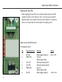
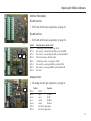
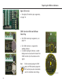
Service Manual
Sartorius Midrics Series
Models MW1P | MW2P | MW1S | MW2S
for Complete Midrics Scales
Models MIS1 | MIS2
for Midrics Indicators
and
Models
MAPP1 | MAPS1
MAPP4 | MAPS4
for Midrics Weighing Platforms
including Service Specifications
Mi111101.eps
WMI5005-e07113
Contents
Overview
General Information
Service Concept
Information
Overview of the Models
Auxiliary Service Tools and Equipment
Accompanying Literature
04
04
04
05
05
06
Interface Description
RS-232 Interface
RS-485 Interface
RS-485 Analog Interface
Digital I/O Interface
COM1 Interface With and Without Clock Chip
17
17
17
17
18
18
Adjusting the Weighing Platform
Description of the Equipment
Indicators
Function of the Switches
Menu Access Switch
07
08
08
Repairing the Midrics Indicator
Repairing the Indicator
Replacing the Front Panel
Blank Display
Replacing the Power Cable
Replacing the Power PCB
Points of Measurement
Replacing the Main PCB
Quick-test of the A/D Converter
Pin Assignment Chart
Replacing the Main PCB
Terminal Assignments in Midrics Indicators
2
09
10
11
11
12
13
14
14
14
15
16
Adjusting the Weighing Platform
Junction Box 1
Pin Assignments in the Junction Box 1
Junction Box 2
Cable from the Load Cell
to the Junction Box 2 (Terminals)
Cable from the Load Cell
to the Junction Box (Terminals)
Adjusting the Off-center Load
Setting the Overload Stops
1. Weighing Platforms with One Load Cell: Steel
2. Weighing Platforms with Four Load Cells: Steel
3. Weighing Platforms with One Load Cell:
Stainless Steel
4. Weighing Platforms with Four Load Cells:
Stainless Steel
19
20
21
22
23
24
26
27
27
27
28
28
Contents
Repairing the Weighing Platforms
Replacing the Connecting Cable
Replacing Load Cells
Torque Values
Replacing the Load Cell Foot
Color Codes of the Wiring
for Weighing Platforms, Models MAPS
Wiring Diagram for the Load Cells (Junction Box 2)
Connections in the Junction Box
for the Load Cells 1-4
Connections in the Junction Box
for the A/D Converter
29
30
31
32
32
32
33
33
40
41
42
42
43
43
43
44
44
Error Codes
Service Specifications
Service Specifications MW...-L / MAP...-L
Service Specifications MW...-LCE / MAP...-LCE
Service Specifications MW...-NCE / MAP...-NCE
Service Specifications MW...-NCE / MAP...-NCE
Sample Calculation Based on Diagram 2
Resistors Available in the E24 Series (+/- 5%):
Selecting the Adjustment Resistor
Adjusting Off-center Load with 1000 Ohms Initial
Resistance
Selecting the Adjustment Resistor:
Diagram 1
Adjusting Off-center Load with 350 Ohms
Initial Resistance
Diagram 2
Adjusting Off-center Load with 1000 Ohms
Initial Resistance
34
35
36
37
Err 101-343 ; InF 01-06
InF 07-73
InF 74-99
45
46
47
Description of the Equipment
Adjusting the Weighing Platform
Load Cell Connection (Color Assignments)
Determining the Resistance for Adjustment
of the Off-center Load
Determining Resistance Values
38
Activating the Service Mode
Configuring the A/D Converter
48-49
50-51
39
39
3
Overview
General Information
Service Concept
Prerequisites for performing maintenance and repair work on Sartorius Midrics
scales requires considerable experience with both indicators and weighing platforms.
In case of defects, repairs are performed on site. Generally, the equipment is not
replaced.
– Do not connect or disconnect cables to or from the equipment; always
disconnect the power cable from the wall socket (mains supply) first!
Information
– To ensure safety, an isolating transformer must be installed between the
indicator and the power supply before performing work that entails opening
the Midrics indicator housing.
On complete Midrics scales, check and adjust as necessary:
–
–
–
–
Repeatability (standard deviation)
Off-center load
Span
Linearity
(The procedure is the same as for all scale and weighing platform models.)
4
Overview | General Information
Overview of the Models
The hardware configuration consists of either a Midrics 1 or 2 indicator and
Sartorius weighing platform(s), or a Midrics 1 or 2 indicator and weighing
platform(s) (strain-gauge load cells) from another manufacturer.
Important:
Mechanical and electrical service or repair work on the complete Midrics scale
requires considerable experience, and for this reason should be performed only
by Sartorius technicians trained at the factory. Any attempt to perform repair
work can result in damage to the equipment.
Auxiliary Service Tools and Equipment
In addition to standard tools, you will need the following special tools to work on
the complete Midrics scale:
Qty. Designation
1
1
1
1
Isolating transformer
Flintec LCT-01 load cell tester
Socket wrench, double hexagon, 10-32 mm, square driver (1/2“)
Torque wrench, 10-120 Nm 14x18, stainless steel
5
Overview | General Information
Qty. Designation
1
1
1
2
2
1
1
1
1
1
1
Torque wrench, 60-320 Nm 14x18, stainless steel
Set of open-ended wrenches with sockets
Set of sockets, up to 30 mm (hexagonal, stainless steel)
Transport belt (to move load plates or weighing
platforms; available from specialist suppliers)
Ring lugs (stainless steel; for moving the load plates or
weighing platforms; available from specialist suppliers)
Set open-ended wrenches (spanners)
(up to 24 mm, stainless steel)
Threaded rod, M 16x120, for lifting the weighing platform
(available from specialist supplier)
Set of screwdrivers (slotted)
Set of screwdrivers (Phillips head)
Set of Allen wrenches
Strain gauge simulator
Accompanying Literature
Operating instructions for Complete Midrics 1 | 2 Scales
Operating instructions for Midrics 1 | 2 Indicators
Operating instructions for Painted or Stainless Steel Weighing Platforms
6
WMW6004-e06101
WMI6001-e06101
WMA6037-e06101
98648-014-94
98648-014-89
98648-015-33
Description of the Equipment
The complete Midrics scales from Sartorius are primarily used in industry. Because there are a number of hardware
configurations to choose from, Midrics models are constructed according to customer requirements.
The complete Midrics scale consists of:
– A choice of weighing platforms with capacities from 3 kg to 3000 kg (in stainless steel or steel) and indicators
The Midrics 1 / 2 indicators consist of:
– Front panel with keypad and
digital display (Midrics 2 has
additional keys)
UniCOM ports in several variants*
COM1 interface in 2
versions*
Main PCB with H8S
processor, analog/
digital converter and
DC/DC converter
1 2 3 4 5 6
* Optional
– Midrics indicators
are equipped with either cable
glands or D-Sub 25 connectors.
Power PCB
Note:
AUT23957.JPG
P1250006a.JPG
Additional electronic subassemblies are optional.
7
Description of the Equipment
Function of the Switches
A
open
closed
verriegelungs_schalter.eps
8
This switch must be open to work with the service software or to configure the A/D
converter (e. g., “Trade” configuration). If the menu access switch is closed, the
error message “ACCESS SWITCH LOCKED” is displayed in the service program and
the indicator shows “L” (underload) or “H” (overload). In this case, the A/D
converter cannot be configured. If adjustment is necessary (span, linearity), the
“± 2%” window is active.
Repairing the Midrics Indicator
Indicator
Important:
!
An isolating transformer must be installed between the indicator
and mains before performing work that entails opening the Midrics
indicator housing.
To open the Midrics indicator, remove the four nuts as shown in the illustration on
the left.
Note:
Mi171107.eps
After completing maintenance or repair work, check the seal between the
front panel and the housing body for damage and replace if necessary. If
the Midrics indicator in question has an IP65 protection rating,
a special test procedure is used to check the IP65 protection after the
housing has been closed.
9
Repairing the Midrics Indicator
Replacing the Front Panel
In the case of a defective key, keypad
overlay, or display, the entire front panel
must be replaced.
P1250006b.JPG
P1250006a.JPG
There are two front panel variants, Midrics 1
and Midrics 2. The only difference between
the two is the range of operating keys.
AUT23993.JPG
AUT23993.JPG
If the indicator housing seal is defective, it
must be replaced. When installing a new
seal, make sure it rests entirely within the
housing and is not caught between the
upper and lower housing parts when you
close the indicator.
P1250008.JPG
10
P1250008.JPG
Repairing the Midrics Indicator
Blank Display
If the display is blank (dark), disconnect the equipment from mains, open the
housing and disconnect all cables and wires from the subassemblies.
Then connect the equipment to power again through an isolating transformer and
connect all subassemblies again, measuring the supply voltage in each case.
– The voltage at the power supply output (connector A; see page 12) is
15V ± 0.3 V direct current.
– The output voltages of the DC/DC converter are listed on page 13.
Replacing the Power Cable
– Disconnect the cable from the power source.
– Open the housing.
– Replace the cable
Note:
After replacing the power cable, use
a torque wrench to tighten the cable
gland to 3 Nm
Nm.
pg_netz.jpg
AUT23977a.JPG
11
Repairing the Midrics Indicators
Replacing the Power PCB
– Disconnect the cable from the power source.
– Pry the protective cap from the power PCB.
To do this, insert the end of a slotted-head screwdriver into each of the four
openings on the protective cap and carefully push the retainer clips, located
further down, to one side.
netzt_kappe.jpg
– Remove the protective cap and disconnect the two wires (blue/brown).
A
– Unplug connector A, remove the 2 screws and replace the power supply. After
replaceing the PCB, make sure to return the protective cap to its original
position.
netzteil.jpg
12
Repairing the Midrics Indicators
Points of Measurement
Note:
Use a digital voltmeter
(DC setting) to measure voltages
against ground (earth). No
particular points of measurement
are defined for this procedure; for
this reason, use a thin test pin and
exercise extreme caution to avoid
short-circuiting the equipment.
M4
M2
M3
AUT23902_b.JPG
The various supply voltages
delivered by the DC/DC converter
can be measured at the following
points.
M5
M1
M 1: 15 V ± 5%
M 2: –9.2 V ± 5%
M 3: +9.2 V ± 5%
M 4:
5 V ± 5%
M 5: 3.3 V ± 5%
Input voltage for the DC/DC converter.
Supply voltage for the A/D converter
Supply voltage for the A/D converter
Supply voltage for the digital PCB
Supply voltage
13
Repairing the Midrics Indicators
Replacing the Main PCB
– Before replacing the main PCB, try to read out the data from the main PCB
controller using the service software; if this is successful, you can load the
adjustment data in the controller of the new main PCB once it is installed. In
many cases, this precludes the need to adjust the weighing system.
Quick-test of the A/D Converter
AUT23958_c.JPG
Pin Assignment Chart
14
No.
Signal designation
Meaning
Voltage
1
2
BR_POS
SENSE_POS
4.5V ± 0.18V
3
4
5
OUT_POS
OUT_NEG
SENSE_NEG
6
BR_NEG
Bridge supply voltage (+)
Sense (+)
Bridge supply voltage
Measuring voltage positive
Measuring voltage negative
Sense (-)
Bridge supply voltage
Bridge supply voltage (-)
–4.5V ± 0.23V
Repairing the Midrics Indicators
1. Connect the strain-gauge simulator and turn the switch to simulate different
input signals. The weight readout should be stable.
Main PCB
Replacing the Main PCB
Note:
AUT23961_a.JPG
YDO01M-232
YDO01M-232CLK
without clock chip with clock chip
– Switch off the indicator.
– Press and hold the k key while switching the indicator on again.
All segments are displayed.
– In case of defect, replace the main PCB.
– After replacing the main PCB, use the PpLoadWH8.exe program to load the
software.
Note:
AUT23967.JPG
If communcation problems occur during communication with connected
devices (such as a printer), check the cable connections and the data
transfer parameters first; if the error source is not found, start the
internal test program.
To load the software, COM PCB model YDO01M-232 or YDO01M-232CLK
is required.
Following installation and commissioning of the new main PCB, the
display backlighting should blink on and off.
15
Repairing the Midrics Indicators
Terminal Assignments in Midrics Indicators
COM1 with Variant:
|
UniCOM with Option:
Standard data output
Pin YDO01M-232
Data output Clock RS232
RS485
YDO01M-232CLK YDO01M-232CO YDO01M-485
4-20mA
YDO01M-20MA
Digital I/0
YDO01M-IO
1
LOAD_PRINTER
LOAD_PRINTER
CTS
TXD+
I_out (+)
OUT5_LOW
2
RESET_OUT
RESET_OUT
DTR
TXD-
I_in (-)
OUT5_HIGH
3
5V_OUT
5V_OUT
RXD
RXD+
V_out (+)
OUT4_LOW
4
GND
GND
TXD
RXD-
V_in (-)
OUT4_HIGH
5
CTS
CTS
GND
GND elec. isol.
GND elec. isol.
OUT3_LOW
6
DTR
DTR
Universal In
GND elec. isol.
GND elec. isol.
OUT3_HIGH
7
RXD
RXD
MINOR (<)
8
TXD
TXD
9
OUT2_LOW
PARES (=)
OUT2_HIGH
MAJOR (>)
OUT1_LOW
10
SET
11
LOAD_PRINTER
LINE_OUT *
IN5_LOW
OUT1_HIGH
12
RESET_OUT
LINE_OUT *
IN5_HIGH
13
GND
GND *
IN4_LOW
14
GND
GND *
IN4_HIGH
15
5V_OUT
16
5V switched
IN3_HIGH
17
GND
IN2_ LOW
IN3_ LOW
18
GND
IN2_HIGH
19
n.c.
IN1_ LOW
20
LINE_OUT
IN1_HIGH
16
* not electrically isolated
Repairing the Midrics Indicators
Interface Description
RS-232 Interface
• For RS-232 interface pin assignments, see page 16.
RS-485 Interface
• For RS-485 interface pin assignments, see page 16.
AUT23965.JPG
SW2
SW1
AUT23963.JPG
Switch
SW1-1
SW1-2
SW1-3
SW1-4
SW2-1
SW2-2
SW2-3
SW2-4
Function when switch closed
Terminating resistor, transmitting 120 Ω
Bias resistor, , transmitting side (TxD+, pull-up) 680 Ω
Bias resistor, , transmitting side (TxD-, pull-down) 680 Ω
RS-422 mode (open: RS-485 mode)
Terminating resistor, receiving side 120 Ω
Bias resistor, receiving side (RxD+, pull-up) 680 Ω
Bias resistor, receiving side(RXD-, pull-down) 680 Ω
Not used
Analog Interface
• For analog interface pin assignments, see page 16.
SW1
AUT23964.JPG
Switch
SW1-1
open
closed
open
closed
SW1-3
SW1-4
Function
SW1-2 |
open
4-20mA
open
0-10V
closed
0-20mA
closed
0-24mA
For future applications
For future applications
17
Repairing the Midrics Indicators
Digital I/O Interface
• For digital I/O interface pin assignments,
see page 16.
AUT23962.JPG
COM1 Interface With and Without
Clock Chip
• For COM1 variant pin assignments, see
page 16.
AUT23967.JPG
• The COM1 interface is required for
loading software.
• To enable loading of software, a solder
bridge must be closed on the back of the
COM1 interface (see illustration on the
right).
Note:
AUT23968.JPG
18
Before commissioning the COM
ports, the PCBs (and any required
DIP switches) must be checked for
correct installation and settings.
AUT23978.JPG
AUT23978a.JPG
Adjusting the Weighing Platform
Version with the junction box (5)
Part no. 57004-428-01
The illustration on the left shows
GF frame 650x500
1.
2.
3.
4.
5.
Load cell 1
Load cell 2
Load cell 3
Load cell 4
Junction box
or
Jun
k_b
ox.
jpg
3
4
2
5
1
AUT23995.JPG
19
Adjusting the Weighing Platform
Junction Box 1
Junction box; open.
1.1
2.1
3.1
4.1
5.1
4.1
Cable to load cell 1
Cable to load cell 2
Cable to load cell 3
Cable to load cell 4
Connecting cable for A/D
converter / indicator
5.1
2.1
1.1
Contacts to connect
the cable 5.1
Aut15158.jpg
20
3.1
Adjusting the Weighing Platform
Pin Assignments in the Junction Box 1
Color Coding
Connecting cable 5.1 from the junction box (terminals) to the A/D converter/
indicator.
See page 33 for the colors of the wires; the casing is gray and black.
Function:
Shield
BBR_POS (Bridge supply voltage +)
BR_NEG (Bridge supply voltage -)
SENSE_POS (Sense +)
SENSE_NEG (Sense -)
OUT_POS (Measuring voltage positive)
OUT_NEG (Measuring voltage negative)
Terminal:
*
Supply +
Supply Sense +
Sense Signal +
Signal -
* The shield is connected to the housing by means of the cable gland (see page 29).
To connect the cable, the wires must be connected to the inner terminals (marked
in the illustration on page 19).
Note:
The color coding of the connecting cable (A/D converter / indicator to
junction box) might be different when connecting a non-Sartorius
platform to the Midrics indicator.
Aut15158b.jpg
21
Adjusting the Weighing Platform
Junction Box 2
Junction box; open.
1.1
2.1
3.1
4.1
5.1
Cable to load cell 1
Cable to load cell 2
Cable to load cell 3
Cable to load cell 4
Connecting cable for A/D
converter / indicator
1.1 - 4.1
Contacts to connect
the cable 5.1
5.1
AUT23982.JPG
5.1
22
Adjusting the Weighing Platform
Cable from the Load Cell to the Junction Box 2 (Terminals)
Color Coding
See page 33 for the colors of the wires; the casing is gray or black.
Kabel3.EPS
Function:
Terminal:
Screen (Shield)
BBR_POS (Bridge supply voltage +)
BR_NEG (Bridge supply voltage -)
SENSE_POS (Sense +)
SENSE_NEG (Sense -)
OUT_POS (Measuring voltage positive)
OUT_NEG (Measuring voltage negative)
OUT_POS (Measuring voltage positive)
Supply +
Supply Sense +
Sense Signal +
Signal Signal +
To connect the cable, the wires must be connected to the inner terminals (marked
in the illustration on page 20/22).
Note:
Note:
AUT23982.JPG
The color coding of the connecting cable (A/D converter / indicator to
junction box) might be different when connecting a non-Sartorius
platform to the Midrics indicator.
23
Adjusting the Weighing Platform
Cable from the Load Cell to the Junction Box (Terminals).
See below for the colors of the wires; the casing is gray.
Colors:
Ye (yellow)
Bl (blue)
Blk (black)
Gn (green)
Gr (gray)
Rd (red)
Wh (white)
Function:
=
=
=
=
=
=
=
Shield
BR_POS (Bridge supply voltage +)
BR_NEG (Bridge supply voltage -)
SENSE_POS (Sense +)
SENSE_NEG (Sense -)
OUT_NEG (Measuring voltage negative)
OUT_POS (Measuring voltage positive)
Terminal:
Supply +
Supply Sense +
Sense Signal Signal +
AUT24000.JPG
The terminal strip designations and the order of the terminals (1 - 4) are marked
on the PCB.
The sequence of the pin assignments of the terminals (1 - 4) should run from the
outside to the inside.
24
Adjusting the Weighing Platform
Procedure for Off-center Load Adjustment
Proceed as follows to adjust the off-center load using the junction box:
– Stand the weighing platform (with 4 load cells) on its side and secure it in this
position.
– Remove the four screws (S) from the junction box.
– Pull approximately 20 to 30 cm of the load cell cables out of the platform (see
arrow).
– Return the weighing platform to the horizontal and position it next to the
junction box.
AUT23995b.JPG
S
– The junction box is now accessible for adjustment of the resistors.
– At the conclusion of off-center load adjustment, follow the instructions above
in reverse order to reassemble the weighing platform.
Important:
!
Make sure to push the cables back into the weighing platform.
AUT23997a.JPG
25
Adjusting the Weighing Platform
Adjusting the Off-center Load
Junction Box 1
If the weighing platform has only 1 load cell, the off-center load is not adjusted in
case of error. The load cell must be replaced.
The off-center load is adjusted only in weighing platforms that have 4 load cells.
Mechanical asymmetries can result in off-center loading errors that exceed
permissible tolerance limits. Such errors must be compensated by soldering resistors
to the PCB in the junction box.
The 4 solder bridges for the resistors are short-circuited at the factory (see the
illustration on the left; note the 4 solder bridges and the sequence of the load cells).
Aut15158c.jpg
Junction Box 2
Note:
The off-center load is adjusted only in weighing platforms that have 4 load
cells.
Mechanical asymmetries can result in off-center loading errors that exceed
permissible tolerance limits. Such errors must be compensated by soldering resistors to the PCB in the junction box.
The 4 solder bridges for the resistors are short-circuited at the factory (see the
illustration on the left; note the 4 solder bridges and the sequence of the load cells).
AUT23982b.JPG
26
To minimize the off-center loading error, use the load cell with the lowest readout
value as a reference. Then adjust the other load cells to this value by adding
resistors.
Adjusting the Weighing Platform
Setting the Overload Stops
1. Weighing Platforms with One Load Cell: Steel
AUT24013.JPG
Platform nominal
capacity in kg
Test weight for
middle stops in kg
3
6
15
30
60
150
300
—
—
—
—
—
—
—
Test weight for
corner stops in kg
3
6
15
30
60
150
300
+
+
+
+
+
+
+
10%
10%
10%
10%
10%
10%
10%
2. Weighing Platforms with Four Load Cells: Steel
Platform nominal Test weight for Test weight for
capacity in kg
middle stops
capacity in corner
in kg
stop in kg
150
300
600
1500
3000
—
—
—
—
—
—
—
—
—
—
Nominal load cell
measurement path
in mm (in kg)
0.4 (MP58T-91kg)
0.4 (MP58T-227kg)
0.6 (MP58T-454kg)
0.6 (MP58T-1134kg)
1.0 (MP58T-2268kg)
AUT24003a.JPG
27
Adjusting the Weighing Platform
3. Weighing Platforms with One Load Cell: Stainless Steel
Platform nominal
capacity in kg
Test weight for
middle stops in kg
3
6
15
30
60
150
—
—
—
—
—
—
Test weight for
corner stops in kg
3
6
15
30
60
150
+
+
+
+
+
+
10%
10%
10%
10%
10%
10%
AUT23706.JPG
4. Weighing Platforms with Four Load Cells: Stainless Steel
Platform nominal Test weight for Test weight for
capacity in kg
middle stops
capacity in corner
in kg
stop in kg
150
300
600
1500
3000
AUT24003a.JPG
28
—
—
—
—
—
—
—
—
—
—
Nominal load cell
measurement path
mm (in kg)
0.4 (MP58T-91kg)
0.4 (MP58T-227kg)
0.6 (MP58T-454kg)
0.6 (MP58T-1134kg)
1.0 (MP58T-2268kg)
Repairing the Weighing Platforms
approx
Replacing the Connecting Cable
. 3-4mm
If the connecting cable (from junction box to Midrics indicator) needs to be
replaced on a weighing platform with four load cells, or if the load cell needs to be
replaced on a platform with only one load cell , open the Midrics indicator and
disconnect the cable from the terminal strip of the A/D converter.
Unscrew the cable gland; the cable or load cell can now be replaced.
pg9_04.tif
pg9_01.tif
Remove the isolation and connect the new cable:
– Expose approx. 6 cm (2.4 in.) of the wires (3) in the cable.
– Remove the isolation from approx. 1 cm (0.5 in.) of the wires and affix ferrules
to the wire ends.
– Thread the cable through the cable gland.
– The shielding (1) must have contact with the clamps (2). Connection to ground
via the shield.
– After replacing the cable or load cell, use a torque wrench to tighten the cable
gland to 5 Nm.
Note:
On stainless steel models, the IP67 protection must be checked after
closing the junction box.
fct01_23.eps
29
Repairing the Weighing Platforms
Replacing Load Cells
If an off-center load error is detected (platforms with one load cell), or if the
output signal from the load cell is too high or too low (InF 02 is displayed during
span adjustment), replace the load cell.
Because the mechanical construction of the platforms is basically uncomplicated,
no detailed description of the disassembly procedure is included here.
AUT23998JPG
Important:
To replace a load cell in a platform with four load cells, use two eye bolts
(6740-81) in two corners and then lift the weighing platform. Remove
the plastic caps from the bore holes before inserting the eye bolts.
The eye bolts can be ordered under spare part number 6740-81.
AUT23999a.JPG / 6740-81a.jpg
– When reassembling the weighing platform, make sure to replace any plates that
were under the platform frame.
lastz_1.jpg
30
Repairing the Weighing Platforms
– Tighten the load cells with the required torque.
Torque Values
AUT23705.JPG
AUT24012.JPG
Load cell designation
Torque value
Load cell designation
Torque value
SAG type 011469/220kg C3
SAG type 011231/550kg C3
SAG type 011232/1100kg C3
SAG type 011233/1760kg C3
MP58T / 91kg C3
MP58T / 227kg C3
MP58T / 454kg C3
MP58T / 1134kg C3
MP58T / 2268kg C3
SAG type 011241/7.5 kg C3
SAG type 011242/15 kg C3
SAG type 011243/30 kg C3
SAG type 011244/50 kg C3
SAG type 011245/100 kg C3
130Nm
130Nm
130Nm
130Nm
130Nm
130Nm
130Nm
130Nm
130Nm
10Nm
10Nm
10Nm
14Nm
14Nm
SAG type 011246/50 kg C3
SAG type 011247/100 kg C3
SAG type 011248/200 kg C3
SAG type 011252/150 kg C3
SAG type 011253/250 kg C3
SAG type 011290/500 kg C3
SAG type 011293/7,5 kg C3
SAG type 011294/15 kg C3
SAG type 011295/30 kg C3
SAG type 011296/50 kg C3
SAG type 011297/100 kg C3
SAG type 011298/200 kg C3
TEDEA 1510 / 100 kg
TEDEA 1510 / 250 kg
TEDEA 1510 / 500 kg
14Nm
14Nm
14Nm
35Nm
35Nm
35Nm
14Nm
14Nm
14Nm
14Nm
14Nm
20Nm
35Nm
35Nm
35Nm
lastz_drehm071206.xls
– After replacing load cells, you need to check the overload stops and adjust them
if necessary (see page 27-28).
P2020003.JPG
31
Repairing the Weighing Platforms
Replacing the Load Cell Foot
– To replace a load cell foot, use a screwdriver to pry the retainer spring free and
push it out, or loosen the nut and remove the screw (see arrow in the lower
illustration on the left).
Color Codes of the Wiring for Weighing Platforms, Models MAPS...
lastz_2.jpg
Platform size
in mm No.:
Verdrahtungsdiagramm für den Indicator (siehe Seite 33)
1
2
3
4
5
6
320
x 240
blue
green
white
red
gray
black
400
x 300
blue
green
white
red
gray
black
500
x 400
blue
green
white
red
gray
black
650
x 500
1)
blue
green
white
red
gray
black
650
x 500
2)
green
black
red
white
blue
brown
800
x 600
1)
blue
green
white
red
gray
black
x 600
2)
green
black
red
white
blue
brown
1000 x 1000
blue
green
white
red
gray
black
1250 x 1000
blue
green
white
red
gray
black
1500 x 1250
blue
green
white
red
gray
black
1500 x 1500
blue
green
white
red
gray
black
blue
green
white
red
gray
black
800
AUT24001a.JPG
2000 x 1500
1)
32
MAPP
P1
2)
MAPS
S1
Repairing the Weighing Platforms
Wiring Diagram for the Load Cells (Junction Box 2)
Connections in the Junction Box for the Load Cells 1-4
1
5
2
6
3
7
4
2a
Pin assignment
1
2
3
4
5
6
7
1)
Variant 1 1)
Designation
Supply v. pos. (in+)
Supply v. neg. (in-)
Test signal pos. (out+)
Test signal neg. (out-)
Schirmleitung +
Schirmleitung Shield
(V +)
(V -)
Signal +
Signal Sense +
Sense GND
Sartorius Hamburg MP58T, green cable
+ Supply
- Supply
+ Output
- Output
+ Sense
- Sense
screen gr.
2)
Variant 2 2)
red
blue
green
gray
white
black
(Shield)
blue
black
white
red
green
gray
(Shield)
Midrics (011...), gray cable
Kabel3.EPS
A/D Converter
AUT24016_a.JPG
Connections in the Junction Box for the A/D Converter
Pin assignment
Designation
Variant 3 3)
Variant 4 com 4)
1
6
3
4
2
5
(V +)
(V -)
Signal +
Signal Sense +
Sense GND
blue
black / brown
white
red / pink
green
gray
(Shield)
green
black
red
white
blue
brown
(Shield)
3)
Supply v. pos. (in+)
Supply v. neg. (in-)
Test signal pos. (out+)
Test signal neg. (out-)
Shield wire +
Shield wire Shield
MAPP4 / MAPS4...
4)
MAPS1... GF / IG
33
Service Specifications MW...-L / MAP...-L
Example for the order number of a Midrics full range scale: MW1P4-1500RR-LCE
Material |
Design
P
P
MW1
MAP
Model
MW.../MAP...-L
MW.../MAP...-L
MW.../MAP...-L
MW.../MAP...-L
MW.../MAP...-L
MW.../MAP...-L
MW.../MAP...-L
MW.../MAP...-L
MW.../MAP...-L
MW.../MAP...-L
Weighing
capacity
Readability
Number of
load cells
4
4
Reproducibility
(Repeatability)
Permissible
Test
tolerance
weight
s
-
Off-center load
(Eccentricity)
Permissible
Test
tolerance
weight
(±)
Weighing
capacity (kg)
1500
1500
Platform size
mm | order code
RR
RR
Span
Class
Applications
Adjustm.
weight
Test
weight
Resolution
-
L
L
Linearity
Permissible
tolerance
(±)
3 kg
0.0002 kg
1 kg
0.0006 kg
1 kg
0.001 kg
M1
1 kg
3 kg
0.002
kg
6 kg
0.0005 kg
2 kg
0.0015 kg
2 kg
0.002 kg
M1
2 kg
6 kg
0.004
kg
15 kg
0.001 kg
5 kg
0.003 kg
5 kg
0.005 kg
M1
5 kg
15 kg
0.01
kg
30 kg
0.002 kg
10 kg
0.006 kg
10 kg
0.01 kg
M1
10 kg
30 kg
0.02
kg
60 kg
0.005 kg
20 kg
0.015 kg
20 kg
0.02 kg
M1
20 kg
60 kg
0.04
kg
150 kg
0.01 kg
20 kg
0.03 kg
50 kg
0.05 kg
M1
50 kg
150 kg
0.1
kg
300 kg
0.02 kg
50 kg
0.06 kg
100 kg
0.1 kg
M1
100 kg
300 kg
0.2
kg
600 kg
0.05 kg
500 kg
0.15 kg
200 kg
0.2 kg
M1
200 kg
600 kg
0.4
kg
1500 kg
0.1 kg
500 kg
0.3 kg
500 kg
0.5 kg
M1
500 kg
1500 kg
1
kg
3000 kg
0.2 kg
500 kg
0.6 kg
1000 kg
1 kg
M1
1000 kg
3000 kg
2
kg
Tare weight
--(1)
--(2)
--(5)
--(10)
--(20)
--(50)
--(100)
--(200)
--(500)
--(1000)
Permissible
tolerance
(±)
Test weight
TCS
iso CAL
ppm
/K
K
kg
0.7/1.5/2.2/3
kg
0.001
kg
10
n
kg
1.5/3/4/6
kg
0.002
kg
10
n
kg
3/7/11/15
kg
0.005
kg
10
n
kg
7/15/22/30
kg
0.01
kg
10
n
kg
15/30/45/60
kg
0.02
kg
10
n
kg
30/70/110/150
kg
0.05
kg
10
n
kg
70/150/220/300
kg
0.1
kg
10
n
kg
150/300/450/600
kg
0.2
kg
10
n
kg
0.5
kg
10
n
kg
1
kg
10
n
kg
kg
300/700/
1100/1500
700/1500/
2200/3000
just_midrics_e.xls
34
Service Specifications MW...-LCE / MAP...-LCE
Example for the order number of a Midrics full range scale: MW2P1-300FE-LCE
Material |
Design
P
P
MW2
MAP
Model
MW.../MAP...-LCE
MW.../MAP...-LCE
MW.../MAP...-LCE
MW.../MAP...-LCE
MW.../MAP...-LCE
MW.../MAP...-LCE
MW.../MAP...-LCE
MW.../MAP...-LCE
MW.../MAP...-LCE
MW.../MAP...-LCE
Weighing
capacity
Readability
Number of
load cells
1
1
Reproducibility
(Repeatability)
Permissible
Test
tolerance
weight
s
-
Off-center load
(Eccentricity)
Permissible
Test
tolerance
weight
(±)
Weighing
capacity (kg)
300
300
Platform size
mm | order code
FE
FE
Span
Class
Applications
Adjustm.
weight
Test
weight
Resolution
-
LCE
LCE
Linearity
Permissible
tolerance
(±)
3 kg
0.001 kg
1 kg
0.001 kg
1 kg
0.001 kg
M1
1 kg
3 kg
0.002
kg
6 kg
0.002 kg
2 kg
0.002 kg
2 kg
0.002 kg
M1
2 kg
6 kg
0.004
kg
15 kg
0.005 kg
5 kg
0.005 kg
5 kg
0.005 kg
M1
5 kg
15 kg
0.01
kg
30 kg
0.01 kg
10 kg
0.01 kg
10 kg
0.01 kg
M1
10 kg
30 kg
0.02
kg
60 kg
0.02 kg
20 kg
0.02 kg
20 kg
0.02 kg
M1
20 kg
60 kg
0.04
kg
150 kg
0.05 kg
20 kg
0.05 kg
50 kg
0.05 kg
M1
50 kg
150 kg
0.1
kg
300 kg
0.1 kg
50 kg
0.1 kg
100 kg
0.1 kg
M1
100 kg
300 kg
0.2
kg
600 kg
0.2 kg
500 kg
0.2 kg
200 kg
0.2 kg
M1
200 kg
600 kg
0.4
kg
1500 kg
0.5 kg
500 kg
0.5 kg
500 kg
0.5 kg
M1
500 kg
1500 kg
1
kg
3000 kg
1 kg
500 kg
1 kg
1000 kg
1 kg
M1
1000 kg
3000 kg
2
kg
Tare weight
--(1)
--(2)
--(5)
--(10)
--(20)
--(50)
--(100)
--(200)
--(500)
--(1000)
Permissible
tolerance
(±)
Test weight
TCS
iso CAL
ppm
/K
K
kg
0.7/1.5/2.2/3
kg
0.002
kg
10
n
kg
1.5/3/4/6
kg
0.004
kg
10
n
kg
3/7/11/15
kg
0.01
kg
10
n
kg
7/15/22/30
kg
0.02
kg
10
n
kg
15/30/45/60
kg
0.04
kg
10
n
kg
30/70/110/150
kg
0.1
kg
10
n
kg
70/150/220/300
kg
0.2
kg
10
n
kg
150/300/450/600
kg
0.4
kg
10
n
kg
1
kg
10
n
kg
2
kg
10
n
kg
kg
300/700/
1100/1500
700/1500/
2200/3000
just_midrics_e.xls
35
Service Specifications MW...-NCE / MAP...-NCE
Example for the order number of a Midrics full range scale: MW2P1-6DC-NCE
Material |
Design
S
S
MW2
MAP
Model
Weighing
capacity
Readability
Number of
load cells
1
1
Reproducibility
(Repeatability)
Permissible
Test
tolerance
weight
s
-
Off-center load
(Eccentricity)
Permissible
Test
tolerance
weight
(±)
Weighing
capacity (kg)
6
6
Platform size
mm | order code
DC
DC
Span
Class
Applications
Adjustm.
weight
Test
weight
Weighing Capacity 1/
Weighing Capacity 2
MW.../MAP...-NCE
Weighing Capacity 1/
Weighing Capacity 2
MW.../MAP...-NCE
Weighing Capacity 1/
Weighing Capacity 2
MW.../MAP...-NCE
Weighing Capacity 1/
Weighing Capacity 2
1.5
kg
3
3
kg
6
6
kg
15
15
kg
30
30
kg
60
0.0005
kg
0.001
0.001
kg
0.002
0.002
kg
0.005
0.005
kg
0.01
0.01
kg
0.02
1 kg
2 kg
5 kg
10 kg
20 kg
0.001 kg
0.002 kg
0.005 kg
0.01 kg
0.02 kg
1 kg
2 kg
5 kg
10 kg
20 kg
0.001 kg
0.002 kg
0.005 kg
0.01 kg
0.02 kg
M1
M1
M1
M1
M1
1 kg
2 kg
5 kg
10 kg
20 kg
1.5
kg
3
3
kg
6
6
kg
15
15
kg
30
30
kg
60
-
NCE
NCE
Linearity
Permissible
tolerance
(±)
MW.../MAP...-NCE
Weighing Capacity 1/
Weighing Capacity 2
MW.../MAP...-NCE
Resolution
0.001
0.002
0.002
0.004
0.004
0.01
0.01
0.02
0.02
0.04
kg
kg
kg
kg
kg
Tare weight
--(1)
(0.5)
--(2)
(1)
--(5)
(2)
--(10)
(5)
--(20)
Permissible
tolerance
(±)
Test weight
TCS
iso CAL
ppm
/K
K
kg
0.3/0.7/1.1/1.5
1.5/3
kg
0.001
0.002
kg
10
n
kg
0.7/1.5/2.2/3
3/6
kg
0.002
0.004
kg
10
n
kg
1.5/3/4/6
7/15
kg
0.004
0.01
kg
10
n
kg
3/7/11/15
15/30
kg
0.01
0.02
kg
10
n
kg
7/15/22/30
30/60
kg
0.02
0.4
kg
10
n
(10)
just_midrics_e.xls
36
Service Specifications MW...-NCE / MAP...-NCE
Example for the order number of a Midrics full range scale: MW2P4-3000RR-NCE
MW2
MAP
Model
Weighing
capacity
Readability
Number of
load cells
4
4
Reproducibility
(Repeatability)
Permissible
Test
tolerance
weight
s
-
Off-center load
(Eccentricity)
Permissible
Test
tolerance
weight
(±)
Weighing
capacity (kg)
3000
3000
Platform size
mm | order code
WR
WR
Span
Adjustm.
weight
Test
weight
Weighing Capacity 1/
Weighing Capacity 2
MW.../MAP...-NCE
Weighing Capacity 1/
Weighing Capacity 2
60
kg
150
150
kg
300
300
kg
600
0.02
kg
0.05
0.05
kg
0.1
0.1
kg
0.2
20 kg
50 kg
100 kg
0.05 kg
0.1 kg
0.2 kg
50 kg
100 kg
200 kg
0.05 kg
0.1 kg
0.2 kg
M1
M1
M1
50 kg
100 kg
200 kg
60
kg
150
150
kg
300
300
kg
600
Permissible
tolerance
(±)
0.04
0.1
0.1
0.2
0.2
0.4
kg
kg
kg
600
kg
1500
0.2
kg
0.5
500 kg
0.5 kg
500 kg
0.5 kg
M1
500 kg
600
kg
1500
0.4
1
1500
kg
3000
0.5
kg
1
500 kg
1 kg
1000 kg
1 kg
M1
1000 kg
1500
kg
3000
1
2
--(50)
(20)
--(100)
(50)
--(200)
kg
NCE
NCE
kg
Permissible
tolerance
(±)
Test weight
TCS
iso CAL
ppm
/K
K
kg
15/30/45/60
70/150
kg
0.04
0.1
kg
10
n
kg
30/70/110/150
150/300
kg
0.1
0.2
kg
10
n
kg
70/150/220/300
300/600
kg
0.2
0.4
kg
10
n
kg
150/300/450/600
700/1500
kg
0.4
1
kg
10
n
kg
1
2
kg
10
n
(200)
--(1000)
MW.../MAP...-NCE
Weighing Capacity 1/
Weighing Capacity 2
Tare weight
(100)
--(500)
MW.../MAP...-NCE
Weighing Capacity 1/
Weighing Capacity 2
-
Linearity
MW.../MAP...-NCE
Weighing Capacity 1/
Weighing Capacity 2
MW.../MAP...-NCE
Resolution
kg
300/700/
1100/1500
1500/3000
just_midrics_e.xls
Material |
Design
P
P
Class
Applications
(500)
37
Adjusting the Weighing Platform
Load Cell Connection (Color Assignments)
Bridge supply voltage
Brückenspeisespannung
Load cell
manufacturer
Wägezellen
Hersteller
+Excitation/ -Excitation/
+Supply/
-Supply/
+Eingang
-Eingang
Test voltage
Messspannung
Cable construction
+Signal/
+Ausgang
+Output
-Signal/
-Ausgang
-Output
+Sense
-Sense
Anmerkung zur
Kabelausführung
Sartorius Hamburg
(z.B.: MP58T/...)
red
rot
blue
blau
green
grün
gray
grau
white
weiß
black
schwarz
d 5mm, 6 wires, green,
shield grounded
d 5mm, 6 adrig, grün,
Abschirmung geerdet
Combics (011...)
blue
blau
black
schwarz
white
weiß
red
rot
green
grün
gray
grau
d 5mm, 6 wires, green,
shield grounded
d 5mm, 6 adrig, grün,
Abschirmung geerdet
green
grün
black
schwarz
red
rot
white
weiß
blue
blau
brown
braun
TEDEA 1510
GWT-TEDEA_12.12.06.xls
38
Adjusting the Weighing Platform
Determining the Resistance for Adjustment of the Off-center Load
Determining Resistance Values
- Place the test weight on each load cell in turn and write down each displayed
value.
- Using the lowest displayed value as the basis, calculated the resistance values
for the other load cells in accordance with the following equation:
Equation:
R
R = R (0) x G (D) / G (T)
= required resistance (in ohms)
R (0) = Initial resistance in the load cell being adjusted (in ohms), (if not specified
in the specification sheet) measured between Signal + (OUT_POS, positive
measuring voltage) and Signal - (OUT_NEG, negative measuring voltage).
G (D) = Difference between lowest off-center loading error (from reference load
cell) and the off-center load value displayed for the weigh cell (in kg).
G (T) = Test weight applied (in kg)
- Solder the required resistor into the bridge of the load cell being adjusted.
- Then perform calibration/adjustment again.
39
Adjusting the Weighing Platform
Sample Calculation Based on Diagram 2
Initial resistance in the load cell: 1000 ohms.
- Test weight: 500 kg
- Readout for reference load cell = 498 kg (load cell with the lowest readout
value).
- Readout for load cell being adjusted = 501.1 kg
- G (D) = 2.3 kg
R = R(0) x G(D)
G(T)
R = 1000 ohms x 2.3 kg
500 kg
R = 4.6 ohms
In this example, note that the test weight (500 kg) is also distributed over the
other load cells, which means that the weight on the load cell being tested is
somewhat lighter. To compensate for this effect, always use the next higher
resistor value.
R = 4.7 ohms ((resistor to be installed (see page 42)).
40
Adjusting the Weighing Platform
Resistors available in the E24 Series (+/- 5%):
Part no.
57004 - 433 - 01
57004 - 434 - 01
57004 - 435 - 01
57004 - 436 - 01
57004 - 437 - 01
57004 - 438 - 01
57004 - 439 - 01
57004 - 440 - 01
57004 - 441 - 01
57004 - 442 - 01
57004 - 443 - 01
0.39
0.82
1.20
1.60
2.00
2.70
3.00
3.30
3.90
4.70
5.60
ohms
ohms
ohms
ohms
ohms
ohms
ohms
ohms
ohms
ohms
ohms
A set of the resistors listed here (containing 3 of each type) can be ordered under
part no. 69CW0106.
Note:
On stainless steel models, the IP65 protection must be checked after
closing the junction box.
41
Adjusting the Weighing Platform
Selecting the Adjustment Resistor
Adjusting Off-center Load with 1000 Ohms Initial Resistance
Adjustment
resistor
(in ohm)
0
0.39
0.82
1.2
1.6
2
2.7
3
3.3
3.9
4.7
5.6
Test weight
50kg
Test weight
100kg
Test weight
200kg
Test weight
500kg
Test weight
1000kg
0.00 - 0.02
0.02 - 0.04
0.04 - 0.06
0.06 - 0.07
0.08 - 0.09
0.1 - 0.13
0.13 - 0.14
0.15 - 0.16
0.16 - 0.19
0.19 - 0.23
0.23 - 0.27
0.20 - 0.33
0.00 - 0.05
0.05 - 0.07
0.08 - 0.11
0.12 - 0.15
0.16 - 0.19
0.20 - 0.26
0.27 - 0.29
0.30 - 0.32
0.33 - 0.38
0.39 - 0.46
0.47 - 0.55
0.56 - 0.66
Off-center (in kg)
0.0 - 0.1
0.1 - 0.1
0.1 - 0.2
0.2 - 0.3
0.3 - 0.4
0.4 - 0.5
0.5 - 0.6
0.6 - 0.7
0.7 - 0.8
0.8 - 0.9
0.9 - 1.1
1.1 - 1.3
0.0 - 0.1
0.1 - 0.4
0.4 - 0.5
0.6 - 0.8
0.8 - 1.0
1.0 - 1.3
1.3 - 1.5
1.5 - 1.6
1.6 - 1.9
1.9 - 2.3
2.3 - 2.7
2.8 - 3.1
0.0 - 0.3
0.3 - 0.7
0.8 - 1.1
1.2 - 1.5
1.6 - 1.9
2.0 - 2.6
2.7 - 2.9
3.0 - 3.2
3.3 - 3.8
3.9 - 4.6
4.7 - 5.5
5.6 - 6.6
Important: These are calculated (estimated) values
42
Adjusting the Weighing Platform
Selecting the Adjustment Resistor:
Diagram 1
Adjusting Off-center Load with 350 Ohms Initial Resistance
20 kg
6
50 kg
100 kg
(2)
(3)
200 kg
5,5
(1)
5
(4)
Adjustment resistor (in ohms)
4,5
4
500 kg
3,5
(5)
3
2,5
2
1000 kg
1,5
(1)
20 kg
(2)
50 kg
(3)
100 kg
(4)
200 kg
(5)
500 kg
(6)
1000 kg
(6)
1
0,5
0
0
0,5
1
1,5
2
2,5
3
Off-center (in kg)
3,5
4
4,5
5
43
Adjusting the Weighing Platform
Diagram 2
Adjusting Off-center Load with 1000 Ohms Initial Resistance
20 kg 50 kg
6
100 kg
500 kg
200 kg
(5)
5,5
(1)
(2)
(4)
(3)
5
Adjustment resistor (in ohms)
4,5
1000 kg
4
Test load
(kg)
(6)
3,5
3
2,5
2
1,5
1
0,5
0
0
44
0,5
1
1,5
2
Off-center (in kg)
2,5
3
3,5
4
(1)
20 kg
(2)
50 kg
(3)
100 kg
(4)
200 kg
(5)
500 kg
(6)
1000 kg
Error Codes
Error codes are shown on the main display. Err codes are shown continuously; Inf messages are shown for 2 seconds, after
which the program returns automatically to the weighing mode.
Display
Err 101 - 104
Err 320
Err 335
Err 340
Cause
Key is stuck
Key pressed at power on
Program memory defective
Verified weighing platform not compatible
with the connected terminal
Operating parameter memory (EEPROM)
defective
Err 341
Flash lost data
Err 343
Data lost from the memory module for
transaction numbers in external alibi memory
Data output not compatible with output
format
Calibration/adjustment condition
not met; for example, not tared or
there is a load on the weighing pan
Adjustment could not
be completed within a certain time
Built-in calibration weight defective
Inf 01
Inf 02
Inf 03
Inf 06
Solution
Release key or
contact your local Service Center
Contact your local Service Center
Connect a compatible weighing platform
Turn the scale off and then on again.
If Err 340 is still displayed, contact
your local Service Center
Turn the scale off and then on again
If Err 340 is still displayed, contact
your local Service Center
Contact your local Service Center
Change the menu settings
Calibrate only when zero is displayed.
Press ) to tare
Unload the scale
Allow the scale to warm up again and then
repeat the adjustment process
Contact your local Service Center
45
Error Codes
Display
Inf 07
Inf 23
Inf 29
Cause
Function not allowed in scales
verified for use in legal metrology
The load on the scale is too heavy to zero
the readout
Taring is not possible when the gross weight
is a minus value
Error in storing reference value, load is too
light
Error in initializing an application
Minimum load not reached
Inf 30-31
Indicator is in XBPI mode
Inf 71
Cannot store the current weight value
(e.g., if control limits are too low or too high)
Cannot store the current weight value
(e.g., the transaction counter has reached
its limit)
Data not found or unreadable
Inf 08
Inf 09
Inf 22
Inf 72
Inf 73
Solution
Contact your local Service Center
for details on changing settings
Check whether “Tare/zero at power on” is set
(1.12)
Zero the scale
Put a heavier weight on the scale
Contact your local Service Center
Define a lower value for the minimum load
(in the Application settings, menu item 3.6)
Change menu setting or perform “Close” function.
Check the interface and cable.
Contact your local Service Center.
None
None
Contact your local Service Center
Error Codes
Display
Inf 74
Inf 98
Inf 99
NO WP
47
Cause
Function is blocked (e.g., menu is locked)
No weighing platform connected
No weighing platform connected
No weighing platform connected
Solution
None
Connect weighing platform
Connect weighing platform
Connect weighing platform
Description of the Equipment
Activating the Service Mode
e
Switch the device on and immediately (during the initialization of the device) press
)
briefly to display the menu
kk
Click on the menu item Setup
setup
)
WP-1
k
Select Device parameter Setup 1)
1
Click on the menu item Code
(press key k until the Code appears in the display)
Code
1
) If a password is requested at this point, enter the service password (see Appendix) and continue once the
service password has been accepted.
48
Description of the Equipment
)
Select the menu item Code and enter the service password » 202122 «
Use keys ( ) k p
_
1
)
_
Saving the service password
1
(
Code
Return to „Code“ in the service mode.
S
(
Setup
When the service mode is activated an »S« appears in the top right-hand corner of
the display.
S
Return to „Setup“ in the service mode.
S
49
Description of the Equipment
Configuring the A/D Converter
Open the menu access switch
§ Remove the cap that covers the menu access switch on the left-hand side of
the back of the indicator
§ To do this, move the switch to the left (towards the interface connectors).
(„open position“)
Menuws-li.JPG
setup
S
– Activate the service mode (see page 48-49)
WP-1
S
– Select weighing platform and confirm
)
10 2 2
)
50
o S
– Menu item »10 2 1«
– Menu item »10 2 2« to enter
Description of the Equipment
1
S
ADC-CON
S
Stand.
S
Save
o
S
– Select the menu item ADC configuration and confirm
– Select whether a standard configuration (STAND) or a verifiable configuration
(VERIF.) should be carried out (in this example, standard configuration).
§ See (98648-014-89) WMI6001-d07063 Operating Instructions for a detailed
description of the procedure
– Once you have completed the configuration, save the data using the menu item
SAVE.
– The A/D converter can now be treated like any standard weighing platform in
connection with the load sensor.
Note:
Once ADC configuration has been completed, an adjustment of the weighing
platform (calibration/adjustment and linearization) must be carried out
– Close the menu access switch
Menuws-re.JPG
51
Sartorius AG
Weender Landstrasse 94–108
37075 Goettingen, Germany
Internet: http://www.sartorius.com
Copyright by Sartorius AG, Goettingen, Germany.
All rights reserved. No part of this publication
may be reprinted or translated in any form or by
any means without the prior written permission
of Sartorius AG.
The status of the information, specifications and
illustrations in this manual is indicated by the date
given below. Sartorius AG reserves the right to
make changes to the technology, features,
specifications, and design of the equipment
without notice.
Status: November 2007, Sartorius AG, Goettingen,
Germany
Printed in Germany on paper that has been
bleached without any use of chlorine · W1A000 · I.K.
Publication No.: WMI5005-e07113