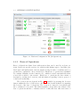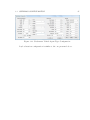
1
User’s Manual
Daniel Castro Silva
c Draft date August 11, 2010
Contents
Contents
i
List of Figures
vi
List of Tables
vii
Preface
1
I
3
Introduction
1 Framework Overview
5
1.1
Introduction . . . . . . . . . . . . . . . . . . . . . . . . . . . . . . . .
5
1.2
Architecture . . . . . . . . . . . . . . . . . . . . . . . . . . . . . . . .
5
2 Installation Guide and Quick Start
2.1
7
Installation Guide . . . . . . . . . . . . . . . . . . . . . . . . . . . . .
7
2.1.1
Simulator . . . . . . . . . . . . . . . . . . . . . . . . . . . . .
7
FSX and FSX Acceleration
. . . . . . . . . . . . . . . . . . .
7
SimConnect SDK . . . . . . . . . . . . . . . . . . . . . . . . .
8
Agent Communication Platform . . . . . . . . . . . . . . . . .
9
2.1.2
users.xml . . . . . . . . . . . . . . . . . . . . . . . . . . . . . 10
addresses.xml . . . . . . . . . . . . . . . . . . . . . . . . . . . 10
2.1.3
Registry . . . . . . . . . . . . . . . . . . . . . . . . . . . . . . 10
i
ii
CONTENTS
2.1.4
Peripheral Components . . . . . . . . . . . . . . . . . . . . . . 12
ControlPanel . . . . . . . . . . . . . . . . . . . . . . . . . . . 12
Monitoring Tool . . . . . . . . . . . . . . . . . . . . . . . . . . 12
Logging and Performance Analysis Tools . . . . . . . . . . . . 12
ATC Agent . . . . . . . . . . . . . . . . . . . . . . . . . . . . 12
Vehicle Control Agent . . . . . . . . . . . . . . . . . . . . . . 13
2.2
II
Quick Start . . . . . . . . . . . . . . . . . . . . . . . . . . . . . . . . 13
Operations
3 Control Panel
15
17
3.1
Introduction . . . . . . . . . . . . . . . . . . . . . . . . . . . . . . . . 17
3.2
Platform Configuration . . . . . . . . . . . . . . . . . . . . . . . . . . 17
3.3
3.2.1
Flight Simulator X . . . . . . . . . . . . . . . . . . . . . . . . 18
3.2.2
Network . . . . . . . . . . . . . . . . . . . . . . . . . . . . . . 19
3.2.3
AgentService . . . . . . . . . . . . . . . . . . . . . . . . . . . 19
3.2.4
Generic Information . . . . . . . . . . . . . . . . . . . . . . . 19
Scenario Configuration . . . . . . . . . . . . . . . . . . . . . . . . . . 20
3.3.1
Bases of Operations . . . . . . . . . . . . . . . . . . . . . . . . 21
Airport . . . . . . . . . . . . . . . . . . . . . . . . . . . . . . 23
Port . . . . . . . . . . . . . . . . . . . . . . . . . . . . . . . . 30
Ground Base . . . . . . . . . . . . . . . . . . . . . . . . . . . 34
3.3.2
No Fly Areas . . . . . . . . . . . . . . . . . . . . . . . . . . . 35
3.3.3
Controllers . . . . . . . . . . . . . . . . . . . . . . . . . . . . . 36
3.3.4
Agent Types . . . . . . . . . . . . . . . . . . . . . . . . . . . . 38
Configuration . . . . . . . . . . . . . . . . . . . . . . . . . . . 41
3.4
Teams Configuration . . . . . . . . . . . . . . . . . . . . . . . . . . . 46
3.4.1
Usable Bases of Operations . . . . . . . . . . . . . . . . . . . 47
3.4.2
Additional No Fly Areas . . . . . . . . . . . . . . . . . . . . . 47
3.4.3
Agents . . . . . . . . . . . . . . . . . . . . . . . . . . . . . . . 47
CONTENTS
iii
Vehicle State . . . . . . . . . . . . . . . . . . . . . . . . . . . 48
Payload Contents . . . . . . . . . . . . . . . . . . . . . . . . . 50
Communications . . . . . . . . . . . . . . . . . . . . . . . . . 51
3.5
Disturbance Configuration . . . . . . . . . . . . . . . . . . . . . . . . 53
3.5.1
Disturbance Location . . . . . . . . . . . . . . . . . . . . . . . 53
3.5.2
Disturbance Availability . . . . . . . . . . . . . . . . . . . . . 54
3.5.3
Disturbance Mobility . . . . . . . . . . . . . . . . . . . . . . . 54
3.5.4
Disturbance Components . . . . . . . . . . . . . . . . . . . . . 57
Size and Growth . . . . . . . . . . . . . . . . . . . . . . . . . 57
3.6
Mission Configuration . . . . . . . . . . . . . . . . . . . . . . . . . . 59
3.6.1
Targets
. . . . . . . . . . . . . . . . . . . . . . . . . . . . . . 60
3.6.2
Requirements . . . . . . . . . . . . . . . . . . . . . . . . . . . 60
3.6.3
Tips . . . . . . . . . . . . . . . . . . . . . . . . . . . . . . . . 60
4 Monitoring Tool
61
4.1
Visual Monitoring . . . . . . . . . . . . . . . . . . . . . . . . . . . . . 61
4.2
Variable Monitoring . . . . . . . . . . . . . . . . . . . . . . . . . . . . 61
5 Logging and Performance Analysis Tool
63
5.1
Logging . . . . . . . . . . . . . . . . . . . . . . . . . . . . . . . . . . 63
5.2
Performance Analysis Tool . . . . . . . . . . . . . . . . . . . . . . . . 63
6 Vehicle Control Agent
6.1
Vehicle Control Agent Interface . . . . . . . . . . . . . . . . . . . . . 65
7 Air Traffic Controller
7.1
III
65
67
Air Traffic Controller . . . . . . . . . . . . . . . . . . . . . . . . . . . 67
Development
8 Developer’s Manual
69
71
iv
CONTENTS
8.1
8.2
The Solution
. . . . . . . . . . . . . . . . . . . . . . . . . . . . . . . 71
8.1.1
MonitoringGroups . . . . . . . . . . . . . . . . . . . . . . . . 72
8.1.2
SimConnectCommonLib . . . . . . . . . . . . . . . . . . . . . 72
8.1.3
SimConnectControlPanel . . . . . . . . . . . . . . . . . . . . . 72
8.1.4
SimConnectATCAgent . . . . . . . . . . . . . . . . . . . . . . 72
8.1.5
SimConnectControlAgent . . . . . . . . . . . . . . . . . . . . 72
8.1.6
SimConnectDisturbancesManager . . . . . . . . . . . . . . . . 73
8.1.7
SimConnectMonitoringAgent . . . . . . . . . . . . . . . . . . 73
8.1.8
SimConnectLoggerAgent . . . . . . . . . . . . . . . . . . . . . 73
8.1.9
SimConnectPerformanceAnalysis . . . . . . . . . . . . . . . . 73
Coding Guidelines
. . . . . . . . . . . . . . . . . . . . . . . . . . . . 73
8.2.1
Files . . . . . . . . . . . . . . . . . . . . . . . . . . . . . . . . 73
8.2.2
Functions and Variables . . . . . . . . . . . . . . . . . . . . . 73
Function Naming . . . . . . . . . . . . . . . . . . . . . . . . . 73
Variables Naming . . . . . . . . . . . . . . . . . . . . . . . . . 73
Event Handlers . . . . . . . . . . . . . . . . . . . . . . . . . . 74
8.3
Deployment of Solution . . . . . . . . . . . . . . . . . . . . . . . . . . 74
Bibliography
75
List of Figures
1.1
Global System Architecture . . . . . . . . . . . . . . . . . . . . . . .
6
3.1
Platform Configuration Tab (Initial) . . . . . . . . . . . . . . . . . . 18
3.2
Platform Configuration Tab (In Operation) . . . . . . . . . . . . . . . 21
3.3
Scenario Configuration Tab . . . . . . . . . . . . . . . . . . . . . . . 22
3.4
Location . . . . . . . . . . . . . . . . . . . . . . . . . . . . . . . . . . 23
3.5
Contact . . . . . . . . . . . . . . . . . . . . . . . . . . . . . . . . . . 24
3.6
Availability . . . . . . . . . . . . . . . . . . . . . . . . . . . . . . . . 25
3.7
Airport . . . . . . . . . . . . . . . . . . . . . . . . . . . . . . . . . . . 26
3.8
Airport Runway . . . . . . . . . . . . . . . . . . . . . . . . . . . . . . 29
3.9
Airport Taxiway
. . . . . . . . . . . . . . . . . . . . . . . . . . . . . 30
3.10 Port . . . . . . . . . . . . . . . . . . . . . . . . . . . . . . . . . . . . 31
3.11 Waterways . . . . . . . . . . . . . . . . . . . . . . . . . . . . . . . . . 32
3.12 Quays . . . . . . . . . . . . . . . . . . . . . . . . . . . . . . . . . . . 33
3.13 Mooring Spaces . . . . . . . . . . . . . . . . . . . . . . . . . . . . . . 34
3.14 Dry Docks . . . . . . . . . . . . . . . . . . . . . . . . . . . . . . . . . 35
3.15 Slipways . . . . . . . . . . . . . . . . . . . . . . . . . . . . . . . . . . 36
3.16 Ground Base . . . . . . . . . . . . . . . . . . . . . . . . . . . . . . . 37
3.17 Roads . . . . . . . . . . . . . . . . . . . . . . . . . . . . . . . . . . . 38
3.18 Area Editing Panel . . . . . . . . . . . . . . . . . . . . . . . . . . . . 39
3.19 Vehicle Selection Screen . . . . . . . . . . . . . . . . . . . . . . . . . 40
3.20 Aircraft Agent Type Configuration . . . . . . . . . . . . . . . . . . . 41
v
vi
LIST OF FIGURES
3.21 Ground Vehicle Agent Type Configuration . . . . . . . . . . . . . . . 43
3.22 Water Vehicle Agent Type Configuration . . . . . . . . . . . . . . . . 44
3.23 Underwater Vehicle Agent Type Configuration . . . . . . . . . . . . . 45
3.24 Teams Configuration Tab . . . . . . . . . . . . . . . . . . . . . . . . . 46
3.25 Aircraft State Panel
. . . . . . . . . . . . . . . . . . . . . . . . . . . 48
3.26 Ground Vehicle State Panel . . . . . . . . . . . . . . . . . . . . . . . 49
3.27 Water Vehicle State Panel . . . . . . . . . . . . . . . . . . . . . . . . 50
3.28 Underwater Vehicle State Panel . . . . . . . . . . . . . . . . . . . . . 51
3.29 Vehicle Payload Contents Panel . . . . . . . . . . . . . . . . . . . . . 52
3.30 Vehicle Communications Panel . . . . . . . . . . . . . . . . . . . . . . 52
3.31 Disturbances Configuration Tab . . . . . . . . . . . . . . . . . . . . . 53
3.32 Disturbance Speed Configuration Panel . . . . . . . . . . . . . . . . . 55
3.33 Disturbance Path Configuration Panel . . . . . . . . . . . . . . . . . 56
3.34 Missions Configuration Tab . . . . . . . . . . . . . . . . . . . . . . . 59
8.1
Dynamic Control Group Box . . . . . . . . . . . . . . . . . . . . . . . 72
List of Tables
8.1
Variable Type Prefixes . . . . . . . . . . . . . . . . . . . . . . . . . . 74
vii
viii
LIST OF TABLES
Preface
This document is intended to serve as a guide to the framework developed by the
author to develop and test coordination methodologies in joint missions, such as
surveillance and search&rescue operations.
The framework is supported by the simulation engine from Microsoft Flight
Simulator X [Microsoft Corporation, ].
The first chapter provides with an overview of the system, it’s key components
and features. The second chapter constitutes the installation guide, showing all the
steps necessary to install the framework in a new computer system. Also, a quick
start guide is included. The third to fifth chapters provide detailed descriptions on
the use of the several key components of the system, namely the Control Panel;
the Monitoring Tool; and the Logging and Performance Analysis Tools. The sixth
chapter provides the developer’s look of the system, detailing how to extend and
modify the framework.
The author would like to acknowledge his PhD supervisors, Luı́s Paulo Reis
and Eugénio Oliveira for all the support and mentoring throughout the years.
1
2
LIST OF TABLES
Part I
Introduction
3
Chapter 1
Framework Overview
The Octopus and its Tentacles
1.1
Introduction
This platform was designed and implemented to serve as a basis for the development
and test of coordination methodologies among vehicles belonging to a team and
performing a common task or mission.
1.2
Architecture
The general architecture of the platform can be seen in Figure 1.1.
5
6
CHAPTER 1. FRAMEWORK OVERVIEW
Performance Analysis
Log Files
Monitoring Tool
Logging Tool
Simulator (FSX)
Control
Panel
Real
Vehicle_n
Disturbances
Manager
ATC
Agent_C
Agent_V
External Module Wrapper_n
Figure 1.1: Global System Architecture
Chapter 2
Installation Guide and Quick Start
Double-click, Next, Next, Next, Install, OK
2.1
Installation Guide
This section of the manual describes how to install the different components of the
framework, including the simulator (Flight Simulator X), the agent communication
platform (AgentService) and the several developed components.
2.1.1
Simulator
Being one of the core components of the framework, installing the simulator should
be the first step to installing the framework on a new system. It is done in several
steps, and comprises not only the simulator itself but also the SDK to provide
programmatic access to the simulator.
FSX and FSX Acceleration
Requirements:
• Flight Simulator X Deluxe Edition
• Acceleration Expansion Pack
Microsoft Flight Simulator X: Gold Edition is a combined package that includes
both FSX Deluxe and Acceleration, and can be bought at a reduced cost, when
compared to buying both products in separate.
7
8
CHAPTER 2. INSTALLATION GUIDE AND QUICK START
Both products should be installed as instructed in the respective packages
(administrative rights are required to install the simulator).
SimConnect SDK
The next step is to install the SimConnect SDK. It should be installed from the
Acceleration DVD. The SDK must be installed not only on the machine running
the simulator, but in all machines belonging to the framework, in order to use the
SimConnect client to access the simulator. After installation, the SDK needs to
be configured. Examples of the several files to be configured, as well as additional
information can be found at
C:\Program Files\Microsoft Games\Microsoft Flight Simulator X
SDK\SDK\Core Utilities Kit\SimConnect SDK\config
assuming that the install directory for SimConnect is
C:\Program Files\Microsoft Games\Microsoft Flight Simulator X SDK
Client Configuration Client configuration must be performed on all machines
where the SDK was installed. The client configuration file is named SimConnect.cfg
and it should be copied to:
C:\Users\<User>\Documents\SimConnect.cfg
<User> being the name of the user with administrative privileges. The file is comprised of several entries with information regarding server location and connection.
An entry should be added for each machine where the simulator (FSX) is installed,
with the following format, <N> starting at 0 (<Port> should be 8765 for uniformity):
[SimConnect.<N>]
Protocol=Ipv4
Address= <IP Address>
Port= <Port>
Server Configuration Server configuration enables applications to connect to
FSX from a remote machine. The server configuration file is named SimConnect.xml
and it should be copied to:
C:\Users\<User>\AppData\Roaming\Microsoft\FSX\SimConnect.xml
2.1. INSTALLATION GUIDE
9
The file should maintain the header information and two SimConnect.Comm parts:
Local IPv4 Server Configuration and Global (remote) IPv4 Server Configuration.
The <Disabled> field should be set to false, and the <Port> field should be set to
8765 (the same as configured in the Client Configuration file, as explained above).
2.1.2
Agent Communication Platform
The chosen Agent Communication Platform for this framework is AgentService. The
latest version can be found at http://www.agentservice.it/, in the Download
section 1 . Requirements:
• AgentService Framework
• Windows Service Intaller
• AgentService External Runtime
• Federation Manager
Agentservice version 1.0.15 was used, but later versions should also work, as long as
backwards compatibility is provided.
Installation instructions can be found in the Manuals page of the Download
section, namely:
• AgentService quick start guide[en]
• Federation Management Suite [en]
• AgentService External Runtime [en]
The AgentService framework, the Windows Service and the External Runtime
should be installed as explained in the manuals above in all machines. A standard
naming convention is suggested, as to simplify deployment. In the example, the
framework was installed in the C:\FEUP\AgentService\Setup\Platform directory,
and each platform was named AgentService.NNN.NNN, where NNN.NNN are the
last two chunks of the IP address of the machine the service is being installed on.
Standard ports used were 8000 for servicePort and 5000 for remotingPort
1
If the resources found on the AgentService website are different or more recent than the ones
mentioned in this manual, please notify the author of the changes
10
CHAPTER 2. INSTALLATION GUIDE AND QUICK START
users.xml
This file contains the credentials for applications to connect to the AgentService
platform. The file should be located at the installation folder root, and should
contain the following:
< Users >
< User
< User
< User
< User
< User
< User
</ Users >
userid = " atcAgent " password = " atcAgent " / >
userid = " logger " password = " logger " / >
userid = " monitoring " password = " monitoring " / >
userid = " airAgent " password = " airAgent " / >
userid = " ctrlPanel " password = " ctrlPanel " / >
userid = " disturbances " password = " disturbances " / >
addresses.xml
located in the RemotePlatformManager installation folder. An entry should be
added for every other machine where AgentService is installed:
<nodeLink ip="192.168.102.201" port="8000"
label="AgentService.102.201" />
In the example, we’re stating that AgentService has been installed also in the machine with IP address 192,168.102.201, as to facilitate deeration discovery.
2.1.3
Registry
XXX Place this here, or leave for automated installer?
These parameters are read by the Control Panel, when if first loads, and can
be altered by it (read section 3.2 for more information on how to change and save
configurations)
HKEY_LOCAL_MACHINE\\SOFTWARE\\FEUP\\LIACC\\MASP
All values are strings, with the exception of NetIPs, which is a multi-string
value.
InstallDir is the folder of the computer where all applications and files should
be located, for instance C:\\FEUP\\MASP.
There are three keys (folders) under the main key, each containing a variable
number of values:
2.1. INSTALLATION GUIDE
11
• App This section contains generic platform parameters
– BaseLogDir This parameter specified the base directory for storing all
log files. A folder will be created under this directory for each simulation
session, and all files pertaining to that simulation session will be kept
there.
– NetIPs This parameter specifies the IP addresses of machines that are
configured to run the software from this platform
• AS This section contains parameters related to AgentService and agent communication
– ServerIP This parameter specified the IP address of the machine AgentService is running on
– ServerPort This parameter specifies the Port in which AgentService is
listening
– ServerName This parameter specifies the name of the AgentService
platform (it must coincide with the one specified during AgentService
install)
• FSX This section contains parameters related to Flight Simulator X
– IP This parameter specifies the IP address of the machine the simulator
is running on.
In addition to the parameters listed above, the AS section has six additional
keys, each containing three values that identify the application in the AgentService
platform. The three parameters are:
• AppName The name used by application (which can be complemented by
an identifier, in some cases)
• Username The username used by the application to authenticate with AgentService
• Password The password used by the application to authenticate with AgentService
The values for Username and Password are the ones listed in the users.xml file,
as shown above. The six keys and the AppName parameter default values are:
• Agent The vehicle control application. AppName: Agent
12
CHAPTER 2. INSTALLATION GUIDE AND QUICK START
• ATC The air traffic controller application. AppName: ATC
• ControlPanel The control panel, which is the main application of the platform. AppName: ControlPanel
• Disturbances The application that manages the disturbances in the environment. AppName: Disturbances
• Logger The application that collects data from the simulator and stores it
into log files. AppName: Logger
• Monitoring The application that is used for real-time monitoring of the platform. AppName: Monitoring
2.1.4
Peripheral Components
ControlPanel
The ControlPanel does not need to be installed. However, existing configuration
files (Scenario, Teams, Disturbances and Mission) should be present in the system
running the ControlPanel.
Monitoring Tool
The Monitoring Tool does not need to be installed.
Logging and Performance Analysis Tools
The Logging Tool does not need to be installed. It should be run on the same
computer as the Control Panel. The Performance Analysis Tool also doesn’t need
to be installed. It should also be run in the same computer, and only after the
simulation is over.
ATC Agent
The ATC Agent is initiated automatically via the ControlPanel, in as many instances
as configured in the Scenario Configuration File. No action needed.
2.2. QUICK START
13
Vehicle Control Agent
The Vehicle Control Agent is initiated automatically via the ControlPanel, in as
many instances as configured in the Team Configuration File. No action needed.
2.2
Quick Start
1. Start the simulator (FSX) and run a simulation in the area the mission is to
be conducted.
2. Start the Monitoring and Logging tools.
3. Start the Control Panel, load and launch Scenario, Team, Disturbance and
Mission files.
4. After the mission is concluded, run the Performance Analysis Tool.
14
CHAPTER 2. INSTALLATION GUIDE AND QUICK START
Part II
Operations
15
Chapter 3
Control Panel
Configure, Configure, Configure, Configure, Take an Aspirin
3.1
Introduction
The Control Panel is the central application of the platform, allowing for all configurations to be made.
Configuration of missions starts with the configuration of the platform, and
then goes on to loading the scenario description language file and launching the
controller agents; then the team description language file should be loaded and
the agents launched; after that, the disturbance description language file should be
loaded and the disturbances sent to the environment; finally, the mission description
language file should be loaded, and the mission sent to the corresponding team.
The following sections describe in detail the configuration of the Platform, and
Scenario, Team, Disturbances and Mission files within the Control Panel.
3.2
Platform Configuration
Platform configuration is performed on the Platform Configuration tab of the Control Panel, as shown in Fig. 3.1, which is selected when the Control Panel is
launched.
Configuration information is stored in the system registry and is automatically
read by the Control Panel and used to fill the configuration fields of the several
configuration areas, which are explained in more detail in the following sections.
17
18
CHAPTER 3. CONTROL PANEL
Figure 3.1: Platform Configuration Tab (Initial)
3.2.1
Flight Simulator X
Flight Simulator X’s SDK must be installed on the computer running the Control
Panel (as well as in all computers in the platform network), as explained in section
2.1.1. When the Control Panel is launched, the SimConnect configuration file is read
and all existent connection settings are shown in the FSX Server IP selection box.
The Server IP defined in the current configuration stored in the Windows registry
is used to select the appropriate IP from the selection box.
The Test FSX Connection button should be used to test if FSX is running on
the selected computer, and if a connection can be successfully established with it. If
a connection cannot be established, the icon next to the button will remain red, and
an error message is shown below the Test buttons. If the connection is established,
the icon next to the button will change to green.
3.2. PLATFORM CONFIGURATION
3.2.2
19
Network
The Network configuration section defines which network computers can be used
by the platform. IP addresses are shown in the selection box (the selected IP can
be deleted by pressing the Delete button), and a new IP address can be added by
writing it in the text box beneath the selection box and pressing the Add button.
The Test Network Connections button should be used to test if all network
addresses can be found and all configurations are present in order to run the platform
applications (Air Traffic Controllers, Vehicle Controllers, Disturbances Manager,
Monitoring Application or Logger Application) that can be sent to them.
3.2.3
AgentService
AgentService configuration data is divided into two categories: Generic Server Data
and Application Specific Data. Regarding the first category, server IP address,
Port and Name are shown. The Name must correspond to the Platform Name
configured in the platform installed at the specified IP address (see section 2.1.2
for more details). The Application Specific Data specifies the login information for
all six application types – Control Panel, Air Traffic Controller, Vehicle Controller,
Monitoring Application, Logging Application and Disturbances Manager. Login
information is comprised of a username, password and an application name (for
applications with more than one instance, such as Air Traffic Controllers or Vehicle
Controllers, a suffix will be added to the application name, in order to maintain the
uniqueness of this attribute, as required by AgentService). This information can be
altered by choosing the desired application from the selection box and then pressing
the Save button.
The Test AgentService Connection button should be used to test if all this information is correct, by using each of the Application Specific Data items to connect
to the platform, thus testing. If an error is detected during this test, the icon next
to the button will remain red and a message is shown below the Test buttons. If all
information is used to successfully login to the AgentService platform, the icon next
to the button will turn green, and the Connect button in the AgentService area will
become enabled.
3.2.4
Generic Information
An additional piece of information is displayed on the Platform Configuration tab,
the Base Logging Directory. This directory will be used to store all log files produced
by the application, and can be changed by pressing the Browse button.
20
CHAPTER 3. CONTROL PANEL
The Monitoring Tool button can be used to launch the Monitoring Tool. It
can be launched at any time, either before or while the simulation is running. More
information about the Monitoring Tool is included in Chapter 4 of this Manual.
The Performance Analysis button can be used to launch the Performance
Analysis Tool, to analyze a mission after it is concluded – see Section 5.2 for more
information about the Performance Analysis Tool.
The Save button allows for all currently tested information to be saved to the
system registry.
When the Connect button (in the AgentService area) is pressed, the Control Panel
connects itself to the AgentService Platform, and a new directory is created in the
Base Logging Directory, corresponding to the date and time of the simulation session.
This folder is then used to store all files pertaining to the simulation, including log
files from all applications.
The bottom part of this tab is used to show the status of the Control Panel
and the Platform. On the left side, all messages sent and received by the Control
Panel are shown. On the right side, information is displayed regarding the deployment of the components that comprise the platform. More specifically, information
about each of the four other tabs of the Control Panel (described below) is displayed, including an indication as to whether or not the corresponding file has been
loaded, and if it has been launched. If it was launched successfully, information
is also displayed regarding the number of agents that were deployed (how many
Air Traffic Controllers and how many Vehicle Controllers, for instance). Figure 3.2
shows the Platform Configuration tab when both Air Traffic Controllers and Vehicle
Controllers have been deployed.
3.3
Scenario Configuration
Scenario configuration is performed on the Scenario Configuration tab of the Control
Panel, shown in Fig. 3.3
Scenario configuration is divided into four distinct categories – Bases of Operations, No Fly Areas, Controllers and Agent Types, each of which is detailed in the
following sections.
3.3. SCENARIO CONFIGURATION
21
Figure 3.2: Platform Configuration Tab (In Operation)
3.3.1
Bases of Operations
Bases of Operations define bases with services that can be used by at least one
team. Bases can provide services for vehicles with distinct types of mobility (air,
land, water and underwater), and encompass an airport and/or a marina and/or a
ground base, explained to more detail below. Each base of operations is identified
by a unique identifier, in the format b<N >, which is created automatically when
a new base is added to the scenario. Each base of operations also has a name, a
description, an historical overview, and information regarding location, person of
contact and availability.
The location screen, depicted in Fig. 3.4, available by pressing the Location
button within the Base of Operations, and shows the details available for inputing
the location of the base of operations. The location is composed of an address and
the coordinates for a location. The address usually corresponds to the address of the
base of operations and the coordinates can be for either the base office and center of
22
CHAPTER 3. CONTROL PANEL
Figure 3.3: Scenario Configuration Tab
operations, or a centroid location within the base. The example shown in Fig. 3.4
refers to the Maia Airfield (Aeródromo da Maia), in Maia, Portugal1 .
The contact person is used to indicate who should be contacted in case a team
needs to contact the base. It is important to notice that the contact person for the
base of operations is not necessarily the same as the contact person for the airport,
marina and ground base. Contact details include name, title, institute, position,
and several contacts, such as telephone, cell phone, fax, e-mail address and mailing
address, as shown in Fig. 3.5 – available by pressing the Contact Person button.
Additional details can be added by pressing the Add button. After inputting the
name of the new detail, it becomes available to insert its value. Additional details
can be deleted, and their names can be edited, by clicking the corresponding buttons
next to the detail.
The availability is used to describe the temporal availability of the base of
1
Information retrieved from http://www.pelicano.com.pt/zp_maia.html
3.3. SCENARIO CONFIGURATION
23
Figure 3.4: Location
operations, indicating when the several vehicles can make use of that base. The
availability panel, available by pressing the Availability button, is depicted in Fig.
3.6. A base of operations can be always available (Always Available) or only during
certain time slots (Periodic/Specific). In the latter case, a number of temporal slots
may be specified. For each slot, the start and end day and time are specified and,
if present, periodicity is also specified. The Start Date and End Date for each time
slot can be specified using the date drop down pickers. The Start Time and End
Time can be specified using numeric input or the up and down arrows for each
field (hours, minutes and seconds). If the time slot is to be repeated periodically,
the Periodic checkbox should be checked, and the information regarding periodicity
filled. Periodicity can be defined on a Daily, Weekly, Monthly or Yearly basis, and a
number should also be specified as to indicate the rate of repeatability (for instance,
repeat every two days, repeat every one week, repeat every six months). Also, the
limit dates for the periodicity can also be specified – for instance, a certain time slot
may be repeated periodically on a weekly basis, but only for four years.
Airport
If the base of operations offers services to aerial vehicles (aircraft, helicopters and
others), the airport structure must be specified, as to provide vehicles and controllers
with the necessary information to safely and efficiently navigate and operate in the
airport. Figure 3.7 shows the airport screen and the several items that can be edited.
Generic information about the airport includes the name and a description,
location and contact person, ICAO and IATA codes, and the magnetic variation at
the airport’s location. The location and contact person for the airport have a similar
24
CHAPTER 3. CONTROL PANEL
Figure 3.5: Contact
interface to the one for base of operations location and contact person, as shown
above.
The ICAO code is a four-letter alphanumeric code uniquely designating each
airport around the world. These codes are defined by the International Civil Aviation Organization, and published every trimester in ICAO Document 7910: Location
Indicators. Being a hierarchical, structured system, the first letter of the airport code
identifies a region of the world (a country or a set of countries) (all letters except for
I, J, Q and X are used), and the first two letters identify the country it belongs to.
Portugal has the LP prefix code (Oporto Francisco Sá Carneiro airport is identified
as LPPR, for instance), while the K prefix code is used for continental USA, and a
set of two-letter prefixes for other territories, such as Alaska or Hawaii (the Chicago
O’Hare International Airport is identified as KORD, for instance).
The IATA code is a three-letter code used to identify major airports around the
world (baggage tags, for instance, are IATA codes to identify origin and destination
airports). These codes are defined by the International Air Transport Association
(IATA) and published biannually in the IATA Airline Coding Directory. IATA codes
are not structured, and similar codes may correspond to airports far apart from each
other (Oporto Francisco Sá Carneiro airport is identified as OPO while the Chicago
3.3. SCENARIO CONFIGURATION
25
Figure 3.6: Availability
O’Hare International Airport is identified as ORD).
Magnetic variation (or magnetic declination) is the difference, in degrees, between local magnetic north and geographic north (also known as true north). This
difference exists because of the different locations of the geographic North pole and
the magnetic North pole, plus possible local anomalies, such as iron deposits. The
magnetic variation presents a positive value when the magnetic north is east of
true north, and negative values otherwise. Even though this value is important for
navigation, the simulator already features a magnetic variation model. As such,
even if this value were to be used to correct small discrepancies between simulator
and reality (such as the temporal evolution of the magnetic variation over a base
of operations), it could not be applied to the rest of the environment, or it would
producing incoherent simulations.
Information regarding airports should be entered as rigorously as possible, as
to allow safe operations in the real world. However, the information should also
be consistent with the airport data within the simulator. In most cases, airport
information within the simulator is already consistent with reality. However, some
airports (smaller airfields, or renewals in an existing airport, for instance) may not
be fully represented in the simulator. In those cases, an editing tool should be used
as to edit the data within the simulator as well. One possible tool to use is AFX
26
CHAPTER 3. CONTROL PANEL
Figure 3.7: Airport
(Airport Facilitator X2 ).
Airport information can be extracted from numerous sources in the internet.
Three examples are listed below:
• http://worldaerodata.com/
• http://www.airport-data.com/ (US only)
• http://www.airnav.com/airports/ (US only)
In addition to these sources, geographical information (such as runway and taxiway
coordinates and configuration) can be retrieved from a service such as Google Earth3 ,
Google Maps4 , or Microsoft Live Maps5 .
2
More information available at http://www.flight1.com/products.asp?product=afxv1
http://earth.google.com/
4
http://maps.google.com/
5
http://www.bing.com/maps/
3
3.3. SCENARIO CONFIGURATION
27
Helipads Helipads, or helicopter landing pads, are areas where helicopters can
land. Each helipad is defined by a unique identifier, in the format h<N >, which is
created automatically when a new helipad is added to the airport. Helipad attributes
include a designation, surface type, helipad coordinates and a radius. Helipad designation is the name by which the helipad is referred to (for instance, ’Helipad 1’).
The surface attribute can be filled with the type of material the helipad is paved
with, which includes concrete, asphalt, tarmac, brick, macadam, gravel, sand, dirt,
grass, water, snow or ice, among others. Helipad coordinates should match the center of the helipad. The radius (which can be defined in a number of measurement
units) specifies the area that can be used by a helicopter for landing operations.
Parking Spaces Parking spaces are defined areas within the airport where aircraft
can park, and include ramps and gates. Each parking space is defined by a unique
identifier, in the format p<N >, which is created automatically when a new parking
space is added to the airport. Each parking space also has a type, designation,
description, the parking space location coordinates (which should match the center
of the parking space) and its radius, and an indication of which taxiway it connects
to, along with the coordinates of the connection spot.
Utilities Utilities represent services provided by the airport, or other structures
present within the airport. Examples of utilities include fuel, battery or water
facilities and control tower. Each utility is defined by a unique identifier, in the
format u<N >, which is created automatically when a new utility is added to the
airport.
Fuel Fuel facilities represent the area of the airport that contains fuel, and
can be used to refuel aircraft. Fuel facilities have a designation, a specific location
within the airport, a radius (which indicates the area serviced by that facility, and
where aircraft can park to be refueled), and an indication as to which type of fuel
it provides, and the amount of fuel available.
Battery In a manner similar to Fuel facilities, Battery facilities represent
areas of the airport that contain power outlets that allow aircraft to recharge batteries. Battery facilities have a designation, a specific location within the airport
and a radius (which indicates the area serviced by that facility, and where aircraft
can park to be recharged).
28
CHAPTER 3. CONTROL PANEL
Water In a manner similar to Fuel and Battery facilities, Water facilities
represent areas of the airport that contain water that allow aircraft to resupply.
Water facilities have a designation, a specific location within the airport and a
radius (which indicates the area serviced by that facility, and where aircraft can
park), and the amount of water available.
Tower The control Tower represents the air traffic control tower present in
all airports and some airfields. Even though it does not provide any physical service
to the aircraft, it is important for the aircraft to know that it can not fly over this
area under a given altitude. Towers have a designation, a specific location within
the airport, its radius and height.
Runways Runways are straight, flat and long strips of terrain that can be used
by aircraft to takeoff and land. Figure 3.8 shows the runway editing screen, which
can be accessed by clicking the Runway button in the airport screen.
Each runway is identified by a code in the form r<N 1>−<N 2>, where N 1 and
N 2 are the two designations for both base and reciprocal ends. Runway designations
are numbers, between 01 and 36, which coincide with the magnetic orientation of
the runway, divided by ten – runway 36 is oriented North and runway 09 is oriented
East, for instance. The latitude, longitude and altitude fields should be filled with
the center position of the runway. Length and width can be specified in any unit of
length, by choosing the appropriate unit in the combo boxes in front of the values.
Surface can be filled with the type of material the runway is paved with, just as
with the helipad surface.
Base and reciprocal ends refer to the two orientations of the same runway.
Start and end points should be specified, as well as the specific orientation of the
runway. While there might be cases where that is not the case, in most runways
the start point of the base end will match the end point of the reciprocal end, and
vice-versa.
Taxiways Taxiways are the roads the serve traffic while on the ground, connecting
runways to other areas of the airport, such as parking spaces, hangars or utilities.
Figure 3.9 shows the taxiway editing screen, which can be accessed by clicking the
Taxiway button in the airport screen.
Each taxiway is identified by a unique identifier, in the format x<N >, which is
created automatically when a new taxiway is added to the airport. Each taxiway also
has a designation, its width, surface type and taxiway path. The path is comprised
of a start point, an end point and any number of middle points. All points are
3.3. SCENARIO CONFIGURATION
29
Figure 3.8: Airport Runway
defined by a set of coordinates (latitude, longitude and altitude), and may include
connections to other taxiways or runways. By defining the intersections between
taxiways, a graph will then be constructed with the entire airport layout (runways
and taxiways). It is important to notice that the order in which the points are
specified should match the order within the taxiway.
Hangars Hangars are structures, usually large in dimension, that house aircraft
during repairs or when they are stopped for some time. The hangar editing screen
can be accessed by clicking the Hangars button in the airport screen. Each hangar is
identified by a unique identifier, in the format h<N >, which is created automatically
when a new hangar is added to the airport. Each hangar also has a designation,
a description and the hangar shape definition. The shape of the hangar is defined
30
CHAPTER 3. CONTROL PANEL
Figure 3.9: Airport Taxiway
by a set of three or more vertexes (defined by their coordinates), the height of the
hangar, its useful area, and information regarding doors - the defining vertexes, its
height and width.
Port
If the base of operations provides services to water and/or underwater vehicles, the
port structure must be specified, as to provide these vehicles (boats and submarines)
the necessary knowledge to safely navigate through the port. Figure 3.10 shows
the port screen and the items that can be edited directly – name, description and
magnetic variation – as well as the other items.
The Utilities are similar to the ones presented above, for the airport. The
Location and Contact Person are also similar to the ones presented above for the
base of operations.
Waterways Waterways, in the context of this application, are defined as virtual
unidirectional roads within navigable water courses, as to facilitate traffic in the
port, thus avoiding traffic chaos or even incidents. The waterways panel – Fig. 3.11
– can be accessed by pressing the Waterways button in the Port Panel.
3.3. SCENARIO CONFIGURATION
31
Figure 3.10: Port
Each waterway is identified by a unique identifier, in the format w<N >, which
is created automatically when a new waterway is added. Additionally, each waterway
has a designation, width, depth, and a path. The path is defined in a similar manner,
when compared to the taxiways of an airport (see above).
Quays Quays (also called Wharfs) are structures located by the water (or over the
water), where boats can dock to, and are used to load/unload passengers and/or
cargo. Different types of quays can be identified, depending on configuration or
purposes. Piers, for instance, are structures, typically made out of wood, raised over
water, and normally supported by pillars. The most well known piers are Victorian
era style piers, originally used for leisure, and usually found in the UK and the US
(the most famous one probably being the Santa Monica Pier), although piers can
also be used for working purposes, such as cargo loading. Other types include Moles,
Jetties or Groynes (even though these are usually not used for docking).
Figure 3.12 shows the Quays screen, accessible by pressing the Quays button,
in the Port screen. Each Quay is identified by a unique identifier, in the format
q<N >, which is created automatically when a new quay is added to the port.
Additionally, each quay has a designation, a description, its width, type, surface
and the quay’s path. The path is defined in a similar manner to waterways, and the
surface type can be chosen from a wide range of available possibilities. The type of
quay identifies the specific quay type – pier, jetty, mole or other.
32
CHAPTER 3. CONTROL PANEL
Figure 3.11: Waterways
Berths Berths are spaces where boats can park. Three types of berths are considered here – mooring spaces, dry docks and slipways –, each of which is defined
and described below. Each berth is identified by a unique identifier, in the format
r<N >, which is created automatically when a new berth (of any kind) is added to
the port. Also, there are attributes common to every type of berth, such as the berth
designation, description, and location (latitude, longitude and altitude coordinates
of the center of the berth).
Mooring Spaces In the broadest definition, a vessel is said to be moored
if it is secured to a fixed structure, usually by means of ropes (called mooring
lines). Mooring spaces are portions of water reserved for vessels to dock, located
besides one or more quays, which are used for mooring the boat (as well as for
loading and unloading of people and cargo). Figure 3.13 shows the Mooring Spaces
screen, accessible by pressing the Moorings button, on the Port screen. In addition
to the common attributes, each mooring space also has information regarding its
dimensions – length, width and depth –, as well as information about which types
of vessel can be moored at the specific mooring space, and the manner in which the
vessel should moor to existing quays (specifically, the side of the boat that should
face the quay – port, starboard, bow or stern).
3.3. SCENARIO CONFIGURATION
33
Figure 3.12: Quays
Dry Docks Dry Docks are areas that can be flooded and drained, as to
allow vessels to be floated in when flooded, and also to rest on a dry platform (using
blocks to support the vessel according to keel layout) when the water is pumped
out. Dry docks are usually used for the construction, maintenance, and repair of
vessels. Floating dry docks can also be used as traditional dry docks, in addition
to providing transportation capabilities for large-sized cargo. Figure 3.14 shows the
Dry Docks screen, accessible by pressing the Dry Docks button, on the Port screen.
In addition to the common attributes, each dry dock also has information regarding
its dimensions – length, width, depth and height –, as well as information about
the volume of the dry dock and the water flow (the speed at which water can be
pumped in and out of the dry dock).
Slipways Slipways are ramps located on the shore, by which ships or boats
can be moved to and from the water. They are used for building and repairing
vessels, and also for launching and retrieving smaller boats on their undercarriage.
Figure 3.15 shows the Slipways screen, accessible by pressing the Slipways button,
on the Port screen. In addition to the common attributes, each slipway also has
information regarding its dimensions – length and width –, the inclination of the
34
CHAPTER 3. CONTROL PANEL
Figure 3.13: Mooring Spaces
slipway, the surface type, and the maximum weight it can support.
Ground Base
If the base of operations provides services to ground vehicles, the ground base structure must be specified, as to provide these vehicles the necessary knowledge to safely
navigate through the base. Figure 3.16 shows the ground base screen and the items
that can be edited directly – name, description and magnetic variation – as well
as the other items. The Utilities are similar to the ones presented above, for the
airport. The Location and Contact Person are also similar to the ones presented
above for the base of operations.
Parking Spaces Parking spaces within a ground base are grouped into parking lots. Each parking lot has a designation, a description and a variable number of
parking spaces. Each parking space has a unique identifier, in the format k<N >,
which is generated automatically when a new parking space is added to a parking
lot. Also, each parking space has an indication as to which type of vehicles it is
destined to (light or heavy), the width of the parking space, and the coordinates for
both the start and end points of the space.
3.3. SCENARIO CONFIGURATION
35
Figure 3.14: Dry Docks
Roads All roads within the ground base (and possible roads connecting to it) are
represented in the Roads panel, shown in Fig. 3.17, accessible by pressing the Roads
button in the Ground Base panel.
Each road has a unique identifier, in the format o<N >, which is generated
automatically when a new road is added to the Ground Base. Additionally, each
road has a designation, the road path, and several characteristics: the surface type
and total width of the road, and traffic information – total number of lanes, number
of lanes with traffic in reverse (which can be 0, if the road has only one direction),
and an indication as to whether the traffic is right- or left-handed. The road path
is defined in a similar manner to the taxiways of an airport (see above).
3.3.2
No Fly Areas
No Fly Areas are specific areas that cannot be used by any vehicle (of any team).
Even though the name suggests that it only applies to aircraft, this element is
applicable to any type of vehicle. Areas can be added and deleted in the main
Scenario Panel, by using the Add and Delete buttons, respectively (the Delete button
deletes the area currently selected in the selection box). Each area has a unique
identifier, in the format a<N >, which is created automatically when an area is
added to the scenario. Figure 3.18 shows the Area Editing Panel, which can be
accessed by pressing the Edit button in the No Fly Areas area.
Each area includes information such as denomination, the medium it applies
to (air, land, water and/or underwater), the area definition, and its availability. The
36
CHAPTER 3. CONTROL PANEL
Figure 3.15: Slipways
availability represents when the area cannot be navigated through. For instance, an
area may only be restricted during nighttime or only during weekdays. Availability is
defined in the same manner as the availability for a base of operations (see above).
The area definition can be represented by two means – polygon or circle – each
extruded vertically from minimum to maximum altitudes. Polygons are represented
by three or more vertexes, while circles are defined by a central point (latitude and
longitude) and radius.
A number of utilities are provided by the Area Editing panel, namely polygon
import and export possibility from/to the KML language (which allows for the
definition of the area polygon with another tool, such as Google Earth), and preview
and editing of the area in a Google Maps plugin – the polygon is shown overlaying
satellite imagery of Earth, and the vertexes can be edited, simply by dragging them
in the map; new vertexes can also be added by dragging the ’pseudo-vertexes’ that
exist between vertexes. The edition of the polygon in the map is automatically
reflected on the values shown on the left, so that the polygon is always updated.
3.3.3
Controllers
Controllers are entities that have some degree of control over a given area of space
(such as an Air Traffic Controller). Each controller has a unique identifier, in the
format c<N >, which is created automatically when a new controller is added to
the scenario, and some other properties. A new controller can be added by pressing
the Add button, in the Controllers area, and the currently selected controller can be
deleted by pressing the Delete button. When changes are made to the properties of
3.3. SCENARIO CONFIGURATION
37
Figure 3.16: Ground Base
the currently selected controller, the Save button must be pressed for the changes
to be permanently saved (otherwise, the changes are not taken into consideration).
The Role of the controller serves as a mere indication as to whether the controller has a military or civilian nature.
The action field specifies how vehicles should behave when within the area
controlled by the controller. Possible actions are Obey, Request and Inform. Obey is
the most restrictive action mode: vehicles within the area controlled by the controller
have no autonomy of movement, and have to obey all orders given by the controller.
The Request mode is less restrictive: vehicles within the area have the autonomy
to decide the maneuvers to perform, but still has to confirm all maneuvers with
the controller. Inform is the least restrictive mode: vehicles have the autonomy
to decide and perform maneuvers, and have only to inform the controller of the
maneuvers they are to execute.
Controllers are usually bound to a specific base of operations (such as air
controllers are usually bound to an airport), and hence the base attribute specifies
which base of operations serves as a base for the controller. The specification of
the area over which the controller has jurisdiction is performed by pressing the Area
button (area specification is similar to the one presented in the section above for No
Fly Areas).
A controller can have several roles (for instance, an airport controller entity
is usually comprised of several human controllers, each of which with a particular
area of operations – approach, departure, tower, ground), and for each role a specific
38
CHAPTER 3. CONTROL PANEL
Figure 3.17: Roads
frequency is used. By pressing the Frequencies button, the roles and frequencies of
the controller can be specified.
3.3.4
Agent Types
The Agent Types present in the scenario configuration indicate all types of vehicles
that are available in the scenario (Teams will then instantiate the vehicle type in
the Agents section – see section 3.4.3). Each Agent Type is identified by a unique
identifier, in the format y<N >, which is automatically created by the application
when a new agent type is added (by pressing the Add button). The currently
selected agent type can be deleted by pressing the Delete button. Information
changed directly in the main form regarding an agent type is only saved when the
Save button is pressed. Information regarding Agent Types is divided into five
categories – Simulated Agent, Real Agent, Physical Characteristics, Performance
Indicators and Payload Layout. The first two categories are included in the main
form, while the other three categories can be edited in the Agent Type Configuration
Panel – see below.
3.3. SCENARIO CONFIGURATION
39
Figure 3.18: Area Editing Panel
Regarding the Simulated Agent, the only necessary information is the SimTitle,
a string that uniquely identifies each vehicle within the simulator. This can be
changed through the Vehicle Selection Panel, which can accessed by pressing the
Change button – see Fig. 3.19.
Vehicle selection starts by choosing the vehicle type, then the manufacturer,
the model of the vehicle, and finally the variation. Different vehicle types are usually
stored in different folders in the FSX installation directory, thus facilitating their
distinction into the categories presented in the Category box. However, some additional vehicles may be installed into the wrong folder, which may lead to a vehicle
being classified in a different category. As such, it is possible, for instance, to find
a ground vehicle in the Aircraft category (usually, when this situation occurs, the
manufacturer is not specified and therefore the vehicle will be placed in the manufacturer labeled Various). If the user is not aware of the manufacturer or model
of the vehicle to select, the first element (All ) will show all variations – choosing
All manufacturers will fill the Model box with all possible models of all manufacturers; choosing All models will show all variations (all vehicles if All is also chosen
for manufacturer, or all vehicles of the specified manufacturer if a manufacturer is
specified). Variations are listed in the center of the screen, and include the name
of the variation, and the SimTitle in parentheses. In some cases, variations differ
only in the visual representation of the vehicle within the simulator (in these cases,
40
CHAPTER 3. CONTROL PANEL
Figure 3.19: Vehicle Selection Screen
sometimes only the SimTitle differs). After choosing the specific variation from the
list, the OK button must be pressed for the change to make effect (pressing the
Cancel button will cancel the changes).
Regarding the Real Agent, information regarding the type, manufacturer,
model and variation of the vehicle is included. This information should match
the information retrieved from the Vehicle Selection Screen as much as possible (the
simulated vehicle will perform closer to reality when it corresponds to the actual
vehicle used). However, many vehicles to be used in reality are not present at the
simulator (or haven’t yet been adapted to it), and therefore a vehicle should be selected (in the Vehicle Selection Screen) that more closely matches the performance
of the real vehicle it represents. This is of special importance when considering
augmented or mixed reality simulations.
3.3. SCENARIO CONFIGURATION
41
Configuration
Vehicle configuration encompasses Physical Characteristics, Performance Indicators
and Payload Layout. It can be accessed by pressing the Configuration button, and
it presents a different interface according to the selected vehicle type. The four
possibilities are shown below.
Aircraft The Aircraft Configuration Panel, shown in Fig. 3.20, presents physical,
performance and payload configurations for aircraft.
Figure 3.20: Aircraft Agent Type Configuration
On the left, physical attributes include the dimensions of the aircraft (length,
height and wingspan), the wing area, empty weight and maximum cargo, number
and type of engines, and maximum amount of fuel (or battery, in case the vehicle is
electric). The height of the aircraft should be measured at the highest point (usually
the tail), thus providing the dimensions of a box in which the aircraft could be fit
in. The empty weight is the weight of the aircraft not including fuel, passengers
or cargo. The number and type of engines specifies how the aircraft is propelled.
Engine types include Piston, Jet, Turbine, TurboProp, None e Other. If the aircraft
is powered by fuel, the maximum amount of fuel it can carry should be filled. If, on
the other hand, the aircraft is electric, the maximum amount of available energy is
shown.
At the center, performance attributes include maximum takeoff weight, required runway length, cruise, maximum and stall speeds, climb rate, range, service
42
CHAPTER 3. CONTROL PANEL
ceiling and fuel flow. The maximum takeoff weight is the maximum possible weight
of the aircraft (including cargo, fuel and possible passengers) during takeoff in order
for it to lift from the ground. The required runway length is an indication of the
minimum length a runway must have for the aircraft to takeoff (the aircraft cannot
takeoff in shorter runways). The cruise, maximum and stall speeds indicate the average (normal) speed at which the aircraft operates; the maximum speed at which
it can fly without causing structural damages; and the minimum speed at which
the aircraft can fly without the risk of falling (below this speed, the aircraft cannot
generate enough lift to sustain its own weight). The climb rate is the maximum vertical velocity the aircraft can reach. The service ceiling is the maximum altitude the
aircraft can operate at, and range is the maximum distance the aircraft can travel
without refueling. Fuel flow represents the average fuel consumption of the aircraft,
considering it is flying at cruise speed, in a straight level flight (fuel consumption
usually increases at higher speeds, or during climbs, and decreases at lower speeds
and during descents).
On the right, existing payload stations can be specified, each being identified
by a name. Information of each payload station includes maximum cargo, dimensions and location of the station. New payload stations are added by pressing the
Add button, the currently selected payload station can be deleted by pressing the
Delete button, and information regarding it is only saved when the Save button is
pressed. The sum of the maximum cargo weights of all payloads cannot overpass
the maximum cargo defined in the physical category. The dimensions of the station
(length, width and height) correspond to the dimensions of a rectangular parallelepiped in which the station can be fit to. The location of the station corresponds
to the distance from the center of the aircraft to the center of the payload station.
This location is stored as three displacement measures – X, Y and Z. The X coordinate (corresponding to length) is measured along the longitudinal axis (roll axis)
of the aircraft, and is positive towards the front of the aircraft. The Y coordinate
(corresponding to the width, or wingspan) is measured along the transversal axis
(pitch axis) of the aircraft, and is positive towards the right wing. The Z coordinate (corresponding to height) is measured along the vertical axis (yaw axis) of the
aircraft, and is positive towards the upper part of the aircraft.
Cars Figure 3.21 shows the Ground Vehicle Configuration Panel, with physical,
performance and payload configurations for ground vehicles.
The organization of the panel is similar to the one presented above for aircraft.
Physical attributes include the dimensions of the vehicle (length, width and
height), empty weight and maximum payload, number and type of engines, maximum amount of fuel, and also the number of wheels and wheels with traction. All
3.3. SCENARIO CONFIGURATION
43
Figure 3.21: Ground Vehicle Agent Type Configuration
these attributes are similar to the ones present in aircraft, with the exception of the
number of wheels and the number of wheels with traction.
Performance attributes include cruise and maximum speeds, range of operations, maximum attack angle, minimum 90◦ turn radius, drag coefficient and fuel
flow. Some of these attributes are similar to the ones present in aircraft configuration. The maximum attack angle is the maximum angle formed with the horizontal
plane at which the vehicle can still move safely (if the angle is steeper, the vehicle
may not be able to climb, if traveling upwards, or it may fall, if traveling downwards.
The minimum 90◦ turn radius is the minimum radius required for the vehicle to perform a 90◦ turn (it can be zero, in case the vehicle is able of turning in place).
Payload stations configuration is similar to the one presented above.
Boats Figure 3.22 shows the Water Vehicle Configuration Panel, with physical,
performance and payload configurations for boats.
The organization of the panel is similar to the one presented above for aircraft.
Physical attributes include the dimensions of the vehicle (length, beam and
height), rudder area, empty weight and maximum payload, number and type of
engines, maximum amount of fuel, and also maximum draft, number and total length
of anchor and chord. The maximum draft specified the maximum vertical distance
between the waterline and the bottom of the hull (which is used to determine whether
or not it can navigate in certain water bodies, given their depth). The number
44
CHAPTER 3. CONTROL PANEL
Figure 3.22: Water Vehicle Agent Type Configuration
of anchors specifies how many anchors exist in the boat, and the length specifies
the total length of all anchors (individual anchor length is determined by dividing
the total length by the number o anchors). The number and length of chords
specification is similar to anchor definition. Chords, or mooring lines, are the lines
used to secure the boat in place, when moored to a quay.
Performance attributes include cruise and maximum speeds, range of operations, minimum 90◦ turn radius, drag coefficient and fuel flow.
Payload stations configuration is similar to the one presented above.
Submarines Figure 3.23 shows the Underwater Vehicle Configuration Panel, with
physical, performance and payload configurations for submarines.
The organization of the panel is similar to the one presented above for aircraft.
Physical attributes include the dimensions of the vehicle (length, beam and
height), rudder and seaplane area, empty weight and maximum payload, number
and type of engines, maximum amount of fuel, and also number and total length of
anchor and chord, number of ballast tanks and total volume. Ballast tanks can be
filled with water to increase the weight of the submarine, so it can dive (and also to
some extent be used to balance the submarine). The total volume and number of
tanks should be supplied, if present.
Performance attributes include cruise speed, maximum speed (when traveling
at the surface), maximum underwater speed and vertical speed, maximum depth
at which the submarine can operate without risk of structural damage, range of
operations, minimum 90◦ turn radius, drag coefficient and fuel flow.
3.3. SCENARIO CONFIGURATION
Figure 3.23: Underwater Vehicle Agent Type Configuration
Payload stations configuration is similar to the one presented above.
45
46
3.4
CHAPTER 3. CONTROL PANEL
Teams Configuration
Teams configuration is performed on the Teams Configuration tab of the Control
Panel – see Fig. 3.24
Figure 3.24: Teams Configuration Tab
Each team has a unique identifier, in the format t<N >, which is created
automatically when a new team is added (by pressing the Add button). Each team
also has a name, description, history, purposes and information regarding contact
person (similar to bases of operations – see Fig. 3.5), accessible by pressing the
Contact Person button. Information regarding the team is only saved when the
Save button is pressed. The currently selected team can be deleted by pressing the
Delete button.
The mobility of the team indicates whether or not the vehicles from the team
can move in the selected means – air, land, water and/or underwater. Even though
this is not checked in the current version, at least one vehicle should be added with
motion capability in each of the selected mobility means (for instance, if underwater
3.4. TEAMS CONFIGURATION
47
is checked, at least one submarine should be added to the team).
3.4.1
Usable Bases of Operations
The usable bases of operations indicate which bases of operations can be used by the
specific team. All bases of operations are specified in the designated area, either on
the available or usable list of bases of operations. One or more bases can be selected
from the list of available bases and sent to the list of usable bases, indicating that
the team can use the selected bases, or vice-versa, from the usable to the available
bases list, so that they can no longer be used by the team. Please note that a
base of operations cannot be removed from the usable bases of operations list if a
vehicle belonging to the team is currently configured with its initial location in that
particular base (see below for details on initial location).
3.4.2
Additional No Fly Areas
Additional No Fly Areas are areas that the specific team cannot use, even though
they can be used by other teams. The specification is the same as in the scenario –
see section 3.3.2.
3.4.3
Agents
The agents within a team represent the actual vehicles that compose the team. Each
agent is identified by a unique identifier, in the format a<N >, which is created
automatically when a new agent is added to the team. Also, each agent has a
name, a description, the identification of the vehicle type (which corresponds to
the identifier of the vehicle type, as presented in section 3.3.4), and information
regarding initial location, simulated and real vehicle, vehicle status, payload contents
and communications.
The initial location of a vehicle is given by a base of operations and a location
within that base (parking space for aircraft of round vehicles, or berth for water or
underwater vehicles). Also, information should be provided regarding the orientation
of the vehicle (heading).
Regarding the simulated vehicle, only the tail number is required – this should
be a unique identifier of the vehicle within the simulation platform. Even though
the name suggests that it only applies to aircraft, it is used by every vehicle.
Real vehicle information varies according to the type of vehicle. If the vehicle is
an aircraft, call sign, tail number and name are required. The call sign is a (usually
48
CHAPTER 3. CONTROL PANEL
short) name by which the aircraft is referred to in ATC communications. The tail
number is the aircraft registration, a unique alphanumeric code that identifies an
aircraft (usually visible in the tail section of aircraft). If the vehicle is a car, call
sign, VIN and plate numbers are required. VIN stands for Vehicle Identification
Number, and is a unique serial number used by the automotive industry to identify
individual motor vehicles. The license plate identifies a vehicle in a given country
or geographic area. If the vehicle is a boat or a submarine, call sign, hull number
and name are required. The hull number is a serial identification number given to
a boat or ship, similar to a tail number in aircraft.
Vehicle State
The vehicle state contains information regarding the state of numerous vehicle variables, which differ according to the vehicle type. The Vehicle State Panel can be
accessed by pressing the State button.
Aircraft Figure 3.25 shows the State Panel for an aircraft. On the left, all existing
lights in an aircraft are shown (cabin, logo, wing, recognition, panel, strobe, taxi,
landing, beacon and nav), and the user can choose whether or not they are on by
checking the box next to the name.
Figure 3.25: Aircraft State Panel
3.4. TEAMS CONFIGURATION
49
On the right, some variables are shown, namely the rudder, aileron, elevator,
flaps, fuel (or battery), doors open and gear down. The first three variables are
indicative of the position of the control surfaces of the aircraft. The flaps variable
is indicative of the flaps handle position (the number of positions is present in the
vehicle configuration file in the simulator installation folder, and is usually four).
The fuel variable indicates the amount of fuel actually present in the aircraft (note
that i cannot exceed the maximum possible amount of fuel, as stated in the vehicle
configuration panel – see Fig. 3.20). If the vehicle is electric, the battery level is
required, instead of fuel. Finally, the door state (opened or closed) and gear state
(up or down) can also be indicated.
Ground Vehicle Figure 3.26 shows the state panel for a car. On the left, all
existing lights in a ground vehicle are shown (cabin, front left, front right, rear left
and rear right), and the user can choose whether or not they are on by checking the
box next to the name.
Figure 3.26: Ground Vehicle State Panel
On the right, some variables are shown, namely the equivalent wheel turn
angle, fuel (or battery) and doors open. The last two variables are similar to the
ones presented above. The equivalent wheel turn angle is an indicative angle of how
much the wheels of the vehicle are turned.
Water Vehicle Figure 3.27 shows the state panel for a boat. On the left, all
existing lights in a water vehicle are shown (cabin, masthead, stern, side lights,
towing, all around and strobe), and the user can choose whether or not they are on
by checking the box next to the name.
On the right, some variables are shown, namely the equivalent engine angle,
fuel (or battery), anchor and rudder. The equivalent engine angle is similar to the
50
CHAPTER 3. CONTROL PANEL
Figure 3.27: Water Vehicle State Panel
equivalent wheel turn angle, but for the engines. The anchor variable (if present)
indicates whether or not the anchor is inside the boat, and in the second case to
which extension it is out of the boat. The rudder variable (if present) measures the
angle at which the rudder is turned.
Underwater Vehicle Figure 3.28 shows the state panel for a submarine. On
the left, all existing lights in an underwater vehicle are shown (cabin, rudder, port,
starboard, bow and strobe), and the user can choose whether or not they are on by
checking the box next to the name.
On the right, some variables are shown, namely the equivalent engine angle,
equivalent engine pitch angle, fuel (or battery), anchor, rudder and seaplane. The
equivalent engine pitch angle measures the equivalent angle of the engines in respect
to the horizontal plane.
Payload Contents
Figure 3.29 shows the Payload Contents Panel, accessible by pressing the Payload
Contents button. This panel allows for the specification of the contents of each
payload station (as specified for the vehicle type, in the Scenario Configuration
tab). The contents of the payload station can be comprised of sensors and/or cargo
(even though it is usually only comprised of one of the two).
By selecting an existing payload station from the selection box, information
regarding it is shown on the right, namely its dimensions and maximum allowed
weight (the combined weight of all sensors in the specified payload and/or possible
3.4. TEAMS CONFIGURATION
51
Figure 3.28: Underwater Vehicle State Panel
cargo cannot exceed this value). On the center of the Panel, details of existent
sensors can be seen (by selecting the desired sensor in the selection box), allowing
for changes to be made (changes are only saved when the Save button is pressed) or
the sensor to be deleted (by pressing the Delete button )and also new sensors can be
added (by pressing the Add button). Each sensor (identified in the selection box by a
zero-based index) contains information about the type of sensor, its size and weight,
operational requirements and specifications. The size of the sensor is given by the
length, width and height of a box that encompasses the sensor (and fits within the
payload station). Operational requirements include temperature, humidity, voltage,
current and power consumption of the sensor. Specifications can vary in number
and type, and as such can be added or deleted dynamically (by pressing the Add
button, or the Del button next to the desired specification, respectively), and the
name and value can be edited directly in the interface. On the bottom of the Panel,
the user can state whether or not the selected payload station contains any cargo.
If it does, the type and quantity of the cargo should be indicated.
Communications
Figure 3.30 shows the Vehicle Communications Panel, accessible by pressing the
Communications button.
In this panel, the Active and Stand By frequencies (for vehicle communications
with air traffic control) can be selected, as well as the control frequency for the vehicle
(the frequency used to exchange data with the vehicle).
52
CHAPTER 3. CONTROL PANEL
Figure 3.29: Vehicle Payload Contents Panel
Figure 3.30: Vehicle Communications Panel
3.5. DISTURBANCE CONFIGURATION
3.5
53
Disturbance Configuration
Disturbance configuration is performed on the Disturbances Configuration tab of
the Control Panel – see Fig. 3.31
Figure 3.31: Disturbances Configuration Tab
Each disturbance has a unique identifier, in the format d<N >, which is created automatically when a new disturbance is added. Each disturbance also has
a denomination and the type of the disturbance, along with information regarding
initial location, availability, mobility and information pertaining to each component
of the disturbance.
3.5.1
Disturbance Location
The disturbance location indicates the initial location of the disturbance. Disturbances can be created in a specific location (Fixed ) or at a random location (Random). In the first case, the coordinates of the location must be specified; in the
54
CHAPTER 3. CONTROL PANEL
second case, an area must be specified (using the Area button), and the disturbance will be created at a random location within that area (the Area is defined as
explained in section 3.3.2).
3.5.2
Disturbance Availability
The disturbance availability indicates the temporal availability of the disturbance
(when it is active, and able to be detected).
Disturbances can have a Scheduled or Random start. In the first case, a specific
point in time is indicated; this can be defined as either a timestamp, or a duration
(a temporal offset, counting from simulation start). In the case of a random start, a
time period is indicated (again, either as absolute timestamps or durations, counting
from simulation start), and the disturbance is initiated within that interval.
The end of a disturbance can be scheduled to occur at a specific point in time
(Scheduled ), at any point during a specified time interval (Random), or it can be
Unspecified. In this last case, the disturbance may not have an end, or it can be
determined by other factors, such as mobility or growth pattern. The end of a
disturbance may also be dependent on other external factors, such as weather or the
actions of the team (for instance, a fire ends when it is extinguished, either by the
rain or by the actions of the agents within the environment).
Duration can be entered using either the XML duration data type format
P T hHmM sS, where h, m and s represent the number of hours, minutes and seconds
of the time interval, respectively, H, M and S represent hours, minutes and seconds
indicators, and the remaining letters are required by the format (all letters should be
capitals); in the format hh : mm : ss, where hh, mm and ss represent the number
of hours, minutes and seconds, respectively; or in the format ahbmcs, where a, b
and c represent the number of hours, minutes and seconds, respectively, and h, m
and s represent the hours, minutes and seconds indicators, respectively.
3.5.3
Disturbance Mobility
The disturbance mobility indicates how the disturbance moves throughout the scenario over time. There are several predefined mobility patterns included in the
framework, available in the Motion Type combo box – Stationary, GeneralHeading,
Random, Path and Wind. A Stationary disturbance, as the name implies, does
not move over time. The GeneralHeading mobility indicates that the disturbance
moves in a given generic direction, with some degree of variation. If this option is
selected, both the general heading of the motion and the variation must be speci-
3.5. DISTURBANCE CONFIGURATION
55
fied. Variation is defined as the heading variation (in degrees) and the distribution
of the variation (possible distributions include Normal, Triangular and Uniform).
The Random mobility indicates that the disturbance moves in a random manner. If
this option is selected, the maximum heading variation over a given period of time
must be specified (for instance, the disturbance cannot change its heading more than
45 degrees per minute). If the disturbance follows a predetermined path, the Path
mobility should be specified. If this option is selected, the path should be specified
(by pressing the Path button). Finally, the Wind mobility type indicates that the
disturbance moves with the wind.
If one of the General Heading, Random or Wind motion types is specified, the
user can also specify if the disturbance should be constrained to s specified area, in
which case the area should also be specified, by pressing the Area button (the area
specification is similar to the one presented in section 3.3.2.
If a motion type other than Stationary is specified, the speed of the disturbance
should also be specified, which is done in the Speed Configuration Panel, accessible
by pressing the Speed button – see Fig. 3.32.
Figure 3.32: Disturbance Speed Configuration Panel
The type of speed should be chosen from the existing types in the combo
box – Constant, Linear, Polynomial, Exponential, Logarithmic, Root, Sinusoid and
Custom. For each of these types (with the exception of Custom speed), the generic
equation is shown below, and the coefficients that allow for the configuration of
the equation are made available. In the case of a Polynomial speed, there is the
possibility of adding new coefficients, by pressing the Add Coeff button. In the case
56
CHAPTER 3. CONTROL PANEL
of a Custom speed, the user can specify a custom equation and the variables that
each coefficient refer to, by selecting it from the appropriate combo box next to the
coefficients.
In the case of the Path mobility being specified, the path followed by the
disturbance should be specified using the Path Configuration Panel, accessible by
pressing the Path button – see Fig. 3.33.
Figure 3.33: Disturbance Path Configuration Panel
The path is specified by a list of coordinates. Each point (identified by the
index number, shown in the selection box) possesses a latitude, longitude and altitude. New points can be added to the list by pressing the Add button, and the
currently selected point can be deleted by pressing the Delete button. Information
regarding each point is only saved when the Save button is pressed. In order to
facilitate path editing, the GoogleMaps plugin on the right of the Panel allows for
direct editing of the path – in order to preview changes made to the path using the
form, the Preview button should be pressed – similar to the Area Editing Panel, as
shown in section 3.3.2.
3.5. DISTURBANCE CONFIGURATION
3.5.4
57
Disturbance Components
Each disturbance is comprised of one or more components (that can be added by
pressing the Add button), each identified by a name, and containing information
regarding simulation representation, medium, detection and size. It is important to
notice that components should have different names, as to enable a fast and easy
identification of each of them. The details of the currently selected component are
only saved when the Save button is pressed.
A disturbance component may have a simulation representation – comprised
by the title of the simulated object (which uniquely identifies an object within the
simulator), and the type of object – Vehicle, Special Effect, or Misc Object (which
includes people). The simulation title is chosen by pressing the Change button in
the Simulation area, which opens a Panel similar to the one used to select a vehicle
type (see section 3.3.4). Medium information refers to the medium in which the
component exists / is detectable (air, land, water and/or underwater). Detection
information includes a list of sensors that can be used to detect the given component.
Possible sensors that can be used to detect the component can be added by pressing
the Add button and choosing the desired sensor from the menu that appear. Sensors
can also be deleted from the list by selecting the desired sensors and pressing the
Delete button.
Size and Growth
Size and growth of a component is analyzed here in more detail. A component can
have a fixed or variable size.
In the case of a fixed size, the initial size of the component can be specified
using the Size Panel, available by pressing the Initial Size button.
If the component has a variable size, the user can specify the growth pattern
for the component, as well as minimum and/or maximum sizes. Minimum and
maximum size for the component are specified in a similar manner to initial size
specification (but pressing the Min Size and Max Size buttons, respectively, which
are only enabled if the check box next to it is checked). Growth can be defined as one
of the predefined types – Fixed, Grow, Shrink, variable or spread. Fixed -size components do not need for minimum or maximum sizes or growth pattern to be specified,
since the size will always be the initial size. Grow and Shrink types imply that the
component size can be defined by a monotonic function. A Variable-sized component can increase and/or decrease in size throughout the simulation. Spread is used
for environmental disturbances that spread through the atmosphere (or water), such
as a volatile chemical, or small particles. If Spread is selected, one of several prede-
58
CHAPTER 3. CONTROL PANEL
fined dispersion patterns can be defined – Uniform, Linear, Polynomial, Exponential,
Logarithmic, Root, Sinusoid and Custom Model (which implies the specification of
one of the standard existing dispersion models: AERMOD, CALPUFF, BLP, OCD,
POLGRAPH, ADMS-3 or other external Custom model).
3.6. MISSION CONFIGURATION
3.6
59
Mission Configuration
Mission configuration is performed on the Mission Configuration tab of the Control
Panel – see Fig. 3.34
Figure 3.34: Missions Configuration Tab
A mission is comprised of one or more phases, and it has a denomination, a
description and an indication of which team will execute the mission (using the team
identifiers as seen in section 3.4). Each phase is identified by a unique identifier,
in the format p<N >, which is generated automatically when a new phase is added
to the mission (using the Add button). Each phase also has a mission type, denomination and description, in addition to information regarding areas and targets,
and also possible requirements and/or tips for phase execution. Phase type can be
selected from Base, Conditional and Extra. Base phases can be started immediately
when the mission starts, but Conditional phases will have dependencies on other
phases, can can only be started when certain conditions are met. Extra phases usually have a conditional start; however, even if there are no conditions, this phase
60
CHAPTER 3. CONTROL PANEL
has a lower priority than Base phases, and, as such, it is only executed when there
are enough available resources (it can be executed at the same time if there are
enough resources, or it can only start after completion of one or more Base and/or
Conditional phases, when resources are made available).
Phase areas are the areas where the phase takes place (specification is as shown
in section 3.3.2).
3.6.1
Targets
Targets specify what the phase consists of. Each target has a unique identifier, in
the format t<N >, which is automatically created when a new target is added (by
pressing the Add button)
3.6.2
Requirements
3.6.3
Tips
Chapter 4
Monitoring Tool
Oh, cool, it has a graphical interface!
4.1
Visual Monitoring
Visual monitoring of the status of the simulation can be done in several manners:
• using the Simulator.
• through an ATC Agent.
• through a Vehicle Controller.
4.2
Variable Monitoring
61
62
CHAPTER 4. MONITORING TOOL
Chapter 5
Logging and Performance Analysis
Tool
That’s a lot of data! Let’s mine it!
5.1
Logging
5.2
Performance Analysis Tool
63
64
CHAPTER 5. LOGGING AND PERFORMANCE ANALYSIS TOOL
Chapter 6
Vehicle Control Agent
It moves on its own!
6.1
Vehicle Control Agent Interface
65
66
CHAPTER 6. VEHICLE CONTROL AGENT
Chapter 7
Air Traffic Controller
O’Hare Approach: United 329, your traffic is a Fokker, one o’clock, 3 miles, Eastbound.
United 329: Approach, I’ve always wanted to say this... I’ve got the little Fokker in sight.
7.1
Air Traffic Controller
67
68
CHAPTER 7. AIR TRAFFIC CONTROLLER
Part III
Development
69
Chapter 8
Developer’s Manual
Getting down and dirty
8.1
The Solution
The project was developed using Visual Studio as the Integrated Development Environment. The solution is comprised of several projects, each of which is detailed
below:
• MonitoringGroups
• SimConnectCommonLib
• SimConnectControlPanel
• SimConnectATCAgent
• SimConnectControlAgent
• SimConnectDisturbancesManager
• SimConnectMonitoringAgent
• SimConnectLoggerAgent
• SimConnectPerformanceAnalysis
71
72
8.1.1
CHAPTER 8. DEVELOPER’S MANUAL
MonitoringGroups
This project contains the code for a visual component used by the Monitoring Tool.
Simply said, it is a GroupBox that can be moved by the user at runtime. In more
detail, there are actually two components: DynamicControlGroupBox and DynamicGroupBox. The DynamicControlGroupBox is Fig. 8.1
Figure 8.1: Dynamic Control Group Box
8.1.2
SimConnectCommonLib
This project
8.1.3
SimConnectControlPanel
This project
8.1.4
SimConnectATCAgent
This project
8.1.5
SimConnectControlAgent
This project
8.2. CODING GUIDELINES
8.1.6
73
SimConnectDisturbancesManager
This project
8.1.7
SimConnectMonitoringAgent
This project
8.1.8
SimConnectLoggerAgent
This project
8.1.9
SimConnectPerformanceAnalysis
This project
8.2
Coding Guidelines
8.2.1
Files
8.2.2
Functions and Variables
Function and variable names follow certain guidelines, especially when pertaining
to interface components.
Function Naming
Variables Naming
Variables should contain an indication of their type, as well as a name indicative of
their content.
Variable Prefixes Several variables, namely variables representing interface elements should include a prefix indicative of their type. Table 8.1 lists several interface
elements and their respective prefixes.
74
CHAPTER 8. DEVELOPER’S MANUAL
Label
TextBox
ComboBox
ListBox
GroupBox
Button
CheckBox
Radio Button
lbl
txt
cmbBox
lstBox
grpBox
btn
chkBox
radio
Table 8.1: Variable Type Prefixes
Event Handlers
Event handlers for interface events such as clicking a button or choosing an item
from a combo box, should retain the naming as given by the IDE (which is comprised
of the variable name followed by and underscore followed by the name of the event).
8.3
Deployment of Solution
Deploy the solution to the network - spread the applications to all computers in the
AgentService Federation
Bibliography
[Microsoft Corporation, ] Microsoft Corporation. Flight simulator x.
75