
1
Operation Manual
OM-TFX-1.0 01-16-15
REVOLUTION TFX
INDOOR UNIT
605 Shiloh Road • Plano, Texas 75074 • 972-212-4800
All rights reserved. No part of this work may be reproduced or transmitted in any form or any means, electronic or mechanical, including photocopying and recording, or by any information storage retrieval system without permission in writing from Air Distribution Technologies
IMPORTANT!
READ BEFORE PROCEEDING!
GENERAL SAFETY GUIDELINES
This equipment is a relatively complicated apparatus.
During installation, operation maintenance or service,
individuals may be exposed to certain components or
conditions including, but not limited to: refrigerants,
UV, materials under pressure, rotating components,
and both high and low voltage. Each of these items
has the potential, if misused or handled improperly, to
cause bodily injury or death. It is the obligation and
responsibility of operating/service personnel to identify
and recognize these inherent hazards, protect
themselves, and proceed safely in completing their
tasks. Failure to comply with any of these requirements
could result in serious damage to the equipment and
the property in which it is situated, as well as severe
personal injury or death to themselves and people at
the site.
This document is intended for use by ownerauthorized operating/service personnel. It is
expected that these individuals possess independent
training that will enable them to perform their
assigned tasks properly and safely. It is essential
that, prior to performing any task on this equipment,
this individual shall have read and understood this
document and any referenced materials. This
individual shall also be familiar with and comply with
all applicable governmental standards and
regulations pertaining to the task in question.
CHANGABILITY OF THIS DOCUMENT
In complying with Titus’ policy for continuous product
improvement, the information contained in this
document is subject to change without notice. Titus
makes no commitment to update or provide current
information automatically to the manual owner.
Updated manuals, if applicable, can be obtained by
contacting the nearest Titus Representative or
accessing the Titus website.
Operating/service personnel maintain responsibility
for the applicability of these documents to the
equipment. If there is any question regarding the
applicability of these documents, the technician
should verify whether the equipment has been
modified and if current literature is available from the
owner of the equipment prior to performing any work
on the unit.
CHANGE BARS
Revisions made to this document are indicated with a
line along the left or right hand column in the area the
revision was made. These revisions are to technical information and any other changes in spelling, grammar
or formatting are not included.
REVOLUTION TFX UNIT MODEL NOMENCLATURE
Note: The terms skid and section have the same meaning in this document;
Variable Speed Drive (VSD) and Variable Frequency Drive (VFD) do as well.
TABLE OF CONTENTS
SECTION 1 - GENERAL INFORMATION AND SAFETY........................................................................................13
Introduction....................................................................................................................................................13
About This Manual........................................................................................................................................13
Warranty........................................................................................................................................................13
Responsibility For Safety................................................................................................................................13
SECTION 2 - START-UP AND OPERATION...........................................................................................................14
Before Start-Up.............................................................................................................................................14
Inspecting Fan Assembly.......................................................................................................................15
Inspecting Belts and Sheaves................................................................................................................16
Checking Isolators................................................................................................................................16
Start-Up.........................................................................................................................................................17
Checking Operation of Fans...................................................................................................................17
Checking Operation of Dampers............................................................................................................17
Back Draft Dampers for Dual Fans…………………. ......................................................................17
Airflow Control Dampers.................................................................................................................18
Air Measuring Device Connections..........................................................................................18
Calculating Flow Rate........................................................................................................18
Air Measuring at the Fan Inlets................................................................................................21
Air Measuring at Unit Outside Air Inlets...................................................................................22
AMS-60 Damper......................................................................................................................22
General..............................................................................................................................22
Damper Operation.............................................................................................................22
No Calibration Required....................................................................................................22
Ductwork Inlet Requirements............................................................................................23
Damper Linkage Arrangements........................................................................................23
Damper Configurations.....................................................................................................23
Jumper Selections............................................................................................................24
Input Power......................................................................................................................24
Sequence Of Operation....................................................................................................24
AHU Airflow Station Specifications...................................................................................25
If ASHRAE 90.1 is referenced, also include.....................................................................25
AMS-60 (Indoor Solution).................................................................................................25
Locating and Installing Actuators....................................................................................................26
Damper Blade Orientation..............................................................................................................26
Return Air and Mixing Dampers ..............................................................................................26
Outside Air and Exhaust Air Dampers......................................................................................26
Energize Fan Motors…...........................................................................................................................27
Variable Frequency Drive (VFD) ............................................................................................................27
Check Doors And Latches......................................................................................................................27
Energy Recovery Wheel…………..…………………………...…………………………………………27
Configuring the AHU.......................................................................................................................27
Airxchange® ..................................................................................................................................29
Start-Up Procedure..................................................................................................................29
Innergy tech® ................................................................................................................................30
Start-Up Procedure:.................................................................................................................30
Thermotech® .................................................................................................................................31
Start-Up Procedure:.................................................................................................................31
TABLE OF CONTENTS (CONT’D)
NovelAire® Technologies.................................................................................................................32
Start-Up Procedure:.................................................................................................................32
Indirect Fired Gas Heat Start Up ...........................................................................................................32
Identify the Gas Burner Type.........................................................................................................32
Preliminary Coordination................................................................................................................33
Recommended Tools.....................................................................................................................33
Pre-Start-Up Checklist...................................................................................................................33
Checking the Burner......................................................................................................................34
Starting the Burner.........................................................................................................................35
Application Information...................................................................................................................43
Mechanical Installation...................................................................................................................43
Electrical Installation......................................................................................................................44
Starting The Electric Heater...........................................................................................................45
Operation.......................................................................................................................................................47
Test And Balance..................................................................................................................................47
Setting Limits........................................................................................................................................48
Checking Motors, Belts and Sheaves....................................................................................................48
SECTION 3 - MAINTENANCE................................................................................................................................49
General Requirements.....................................................................................................................................49
Inspect Parts....................................................................................................................................................50
Cabinet...................................................................................................................................................50
Door Hardware and Gaskets..................................................................................................................50
Panels....................................................................................................................................................50
Fan Segment (Supply, Return or Exhaust) .....................................................................................................50
Removing the Fan..................................................................................................................................50
Operating Adjustable Motor Base ...................................................................................................................51
Standard.................................................................................................................................................51
Checking Belt Tension...........................................................................................................................53
Aligning Sheaves ............................................................................................................................................53
Using a Straightedge..............................................................................................................................54
Using a String.........................................................................................................................................54
Belt Replacement Tensioning and Sheave Alignment for Top Mount..............................................................55
Lubrication........................................................................................................................................................56
Checking Condition of Extended Lubrication Lines................................................................................58
Recommended Lubricant for Bearings...................................................................................................58
Proper Interval and Quantity..................................................................................................................58
Lubricating the Fan Segment and Motor..........................................................................................................59
Checking Condition of Mounting Hardware, Adjustable Motor Base and Motor.....................................59
Checking Electrical Connections............................................................................................................59
Keep Motor Bearing Lubricated..............................................................................................................59
UVC Emitter Lamps..........................................................................................................................................61
Three Types of Lamps...........................................................................................................................61
Maintaining and Replacing Filter Segments ...................................................................................................62
Replacing the Filters...............................................................................................................................62
TABLE OF CONTENTS (CONT’D)
Economizer Segment (Dampers)…...................................................................................................................63
Cleaning Procedure................................................................................................................................63
Hardware Check.....................................................................................................................................63
Coil Segment Cleaning......................................................................................................................................63
Tools, Equipment and Materials ............................................................................................................63
Cleaning Procedure................................................................................................................................63
Condensate Drain Pan, Trap and Line Cleaning …..........................................................................................64
Tools, Equipment and Materials.............................................................................................................64
Schedule and Conditions........................................................................................................................64
Cleaning Procedure ...............................................................................................................................64
Coil Freeze Protection............................................................................................................................64
Energy Recovery Wheel....................................................................................................................................65
Airxchange® ....................................................................................................................................................65
Tools and Materials ...............................................................................................................................65
Cleaning the Wheel................................................................................................................................65
Airxchange® ….................................................................................................................................................66
Adjusting Air Seals.................................................................................................................................66
Airxchange® .....................................................................................................................................................67
Inspect Wheel Drive Components..........................................................................................................67
NovelAire® Technologies..................................................................................................................................67
Cleaning the Wheel................................................................................................................................67
Adjusting Air Seals.................................................................................................................................67
Inspect Wheel Drive Components..........................................................................................................67
How to Measure, Assemble and Install..................................................................................................67
Thermotech® ....................................................................................................................................................69
Cleaning the Wheel................................................................................................................................69
Adjusting Air Seals.................................................................................................................................69
Thermotech® ....................................................................................................................................................69
Inspect Wheel Drive Components..........................................................................................................69
Innergy tech® ...................................................................................................................................................70
Cleaning the Wheel................................................................................................................................70
Adjusting Air Seals.................................................................................................................................70
Inspect Wheel Drive Components..........................................................................................................71
Innergy tech® ...................................................................................................................................................71
SECTION 4 - SERVICE AND REPAIR.....................................................................................................................73
Service Tools and Equipment.........................................................................................................................73
Service Information.......................................................................................................................................74
Troubleshooting.............................................................................................................................................74
Pitot Tube......................................................................................................................................................74
Inclined Manometer.......................................................................................................................................75
Minihelic Filter Gauge....................................................................................................................................75
U-Tube Manometer.......................................................................................................................................75
Duct Pressures..............................................................................................................................................76
Velocity.................................................................................................................................................76
Static Pressure.....................................................................................................................................76
Total Pressure......................................................................................................................................77
TABLE OF CONTENTS (CONT’D)
Requesting Assistance...................................................................................................................................77
Adjusting, Removing, and Installing Sheaves.................................................................................................78
Fixed Pitch Sheaves (T.B Woods With Sure Grip Bushings) ................................................................78
Tools and Materials Required.........................................................................................................78
Removing Sheave..........................................................................................................................78
Installing Sheave............................................................................................................................78
Standard Mounting.........................................................................................................................79
Reverse Mounting..........................................................................................................................79
Adjusting Sheave...........................................................................................................................79
Adjustable Pitch Sheaves (T.B. Woods - Model JVS)............................................................................80
Tools and Material Required...........................................................................................................80
Removing Sheave..........................................................................................................................80
Installing Sheave............................................................................................................................80
Adjusting Sheave...........................................................................................................................80
Adjustable Pitch Sheaves (T.B. Woods - Model FHP)............................................................................81
Tools and Material Required...........................................................................................................81
Removing Sheave..........................................................................................................................81
Installing Sheave............................................................................................................................81
Adjusting Sheave...........................................................................................................................82
SECTION 5 - WIRING DIAGRAMS........................................................................................................................83
Temperature................................................................................................................................................99
LIST OF FIGURES
FIGURE 1 - Seismic Isolator ................................................................................................................................... 14
FIGURE 2 - Fan and Motor Isolator Support Frame................................................................................................ 16
FIGURE 3 - Spring Isolator...................................................................................................................................... 16
FIGURE 4 - Counterbalance Locked into Place for Shipping.................................................................................. 17
FIGURE 5 - Counterbalance Unlocked for Start-Up................................................................................................ 17
FIGURE 6 - High And Low Connections For An In Fan Air Monitoring System……………...……………………….21
FIGURE 7 - Port Locations For Fan Mounted Air Monitoring System………………………………………….………22
FIGURE 8 - Ductwork Inlet Requirements…............................................................................................................ 23
FIGURE 9 - Ductwork Radius.................................................................................................................................. 23
FIGURE 10 - 25% Sensing Option .......................................................................................................................... 23
FIGURE 11 - 25%/75% Sensing Option.................................................................................................................. 23
FIGURE 12 - 25%/75% Sensing Option.................................................................................................................. 24
FIGURE 13 - Example of Sweep Balance Results Label On Fan Housing............................................................. 27
FIGURE 14 - Metal Spacers on Doors .................................................................................................................... 27
FIGURE 15 - Vertical Wheel for Indoor AHU ........................................................................................................... 27
FIGURE 16 - Horizontal Wheel………………………………….………………………………………………………...28
FIGURE 17 - Energy Recovery Wheel - Pulley Side............................................................................................... 29
FIGURE 18 - Segment Retainer.............................................................................................................................. 30
FIGURE 19 - Diameter Seal Adjustment ................................................................................................................. 30
FIGURE 20 - Purge Angle Detail ............................................................................................................................. 31
FIGURE 21 - Purge Angle Detail ............................................................................................................................. 32
FIGURE 22 - Gas Furnace Condensate Drain Trap................................................................................................ 34
FIGURE 23 - Open Fuse Disconnects .................................................................................................................... 35
FIGURE 24 - Set Id Fan Damper ............................................................................................................................ 35
FIGURE 25 - Check Main Gas Supply Pressure..................................................................................................... 35
FIGURE 26 - Draft Over Fire Test Port .................................................................................................................... 36
FIGURE 27 - Flue Combustion Temperature and Efficiency Test Port- ID Blower .................................................. 36
FIGURE 28 - Damper Actuator................................................................................................................................ 36
FIGURE 29 - Typical Wiring Diagram ...................................................................................................................... 41
FIGURE 30 - Minimum Air Velocity Required for Safe Operation............................................................................ 45
FIGURE 31 - Pressure Probe Direction................................................................................................................... 46
FIGURE 32 - Air Flow Switch Connections ............................................................................................................. 46
FIGURE 33 - V-Belt Drive Kit Label......................................................................................................................... 48
FIGURE 34 - Typical Drive Kit Data Tag.................................................................................................................. 51
FIGURE 35 - Adjustable Motor Base....................................................................................................................... 51
FIGURE 36 - Adjustable Motor Base (Top Mount)................................................................................................... 52
FIGURE 37 - Belt Tensioning .................................................................................................................................. 53
FIGURE 38 - Belt Tensioning Gauge....................................................................................................................... 53
FIGURE 39 - Alignment Using Straight Edge .......................................................................................................... 54
FIGURE 40 - Alignment Using String ...................................................................................................................... 54
FIGURE 41 - Sheave Angular Misalignment ........................................................................................................... 55
FIGURE 42 - Motor Base Lowered.......................................................................................................................... 55
FIGURE 43 - Sheave Angular Alignment................................................................................................................. 56
FIGURE 44 - Sheave Angular Misalignment ........................................................................................................... 56
FIGURE 45 - Sealed Bearing .................................................................................................................................. 56
FIGURE 46 - Bearing with Set Screw Type Locking Device ................................................................................... 57
FIGURE 47 - Bearing with Eccentric Cam............................................................................................................... 57
FIGURE 48 - Split Bearing (Assembled) ................................................................................................................. 57
LIST OF FIGURES CONT’D
FIGURE 49 - Optional Lubrication Lines ............................................................................................... 57
FIGURE 50 - Open Drip Proof (ODP) Motor ......................................................................................... 59
FIGURE 51 - Totally Enclosed Fan Cooled (TEFC) Motor .................................................................... 59
FIGURE 52 - UV Lamps ........................................................................................................................ 61
FIGURE 53 - Installing V-Mod Lamp ..................................................................................................... 61
FIGURE 54 - Installing V-Ray and V-Max Grid Lamps .......................................................................... 61
FIGURE 55 - V-Max Grid Lamps ........................................................................................................... 61
FIGURE 56 - Typical Filters ................................................................................................................... 62
FIGURE 57 - Installing Angle Filters...................................................................................................... 62
FIGURE 58 - Installing Side Load Filters............................................................................................... 62
FIGURE 59 - Rinse Segments .............................................................................................................. 65
FIGURE 60 - Diameter Seal Adjustment ............................................................................................... 66
FIGURE 61 - Airxchange® Energy Recovery Wheel With Bearing Support Beam Side ................... 66
FIGURE 62 - How to Measure............................................................................................................... 68
FIGURE 63 - Disassembly ..................................................................................................................... 68
FIGURE 64 - Assembly .......................................................................................................................... 68
FIGURE 65 - Installation......................................................................................................................... 68
FIGURE 66 - Loosen Screws Before Adjusting Seals ............................................................................ 69
FIGURE 67 - Airloop™ Labyrinth Seal Adjustment ................................................................................ 70
FIGURE 68 - ERW Seal Locations ......................................................................................................... 70
FIGURE 69 - Maintenance Requirements.............................................................................................. 72
FIGURE 70 - Construction of Pitot Tube ................................................................................................ 74
FIGURE 71 - Pitot Tube.......................................................................................................................... 74
FIGURE 72 - Inclined Manometer .......................................................................................................... 75
FIGURE 73 - Minihelic Filter Gauge ....................................................................................................... 75
FIGURE 74 - U-Tube Manometers ......................................................................................................... 76
FIGURE 75 - Slack Tube Manometer..................................................................................................... 76
FIGURE 76 - Static Pressure Air System ............................................................................................... 77
FIGURE 77 - Inserting Cap Screws........................................................................................................ 78
FIGURE 78 - Standard Mounting ........................................................................................................... 78
FIGURE 79 - Reverse Mounting............................................................................................................. 78
FIGURE 80 - Adjustable Pitch Sheave (JVS) ......................................................................................... 80
FIGURE 81 - Adjustable Pitch Sheave (FHP) ........................................................................................ 81
FIGURE 82 - Full Voltage Starter ........................................................................................................... 84
FIGURE 83 - Full Voltage Starter With Single Point Power Connection (204195) ................................. 86
FIGURE 84 - Transformer Enclosure Wiring Detail (Shown Open)........................................................ 88
FIGURE 85 - Transformer Wiring Diagram............................................................................................. 89
FIGURE 86 - UV Control Panel Wiring (8 amps).................................................................................... 90
FIGURE 87 - Gas Heat, Single Phase, 1500Va Transformer Wiring Diagram ....................................... 91
FIGURE 88 - UV Control Panel Wiring ( greater than 8 amps) .............................................................. 92
FIGURE 89 - Gas Heat, Three Phase, 1000Va Transformer Wiring Diagram........................................94
FIGURE 90 - Gas Heat, Three Phase, 500Va Transformer Wiring Diagram..........................................95
FIGURE 91 - Typical Wiring Diagram for Electric Heat Control Type Vermier .......................................96
FIGURE 92 - Typical Wiring Diagram for Control Type Full SCR ...........................................................97
LIST OF TABLES
TABLE 1 - Torque for Tightening Set Screws........................................................................................ 15
TABLE 2 - Air Measuring Device Connections...................................................................................... 19
TABLE 3 - Indoor Unit Example ............................................................................................................ 25
TABLE 4 - Gas Heat Segment Model Number Nomenclature .............................................................. 37
TABLE 5 - Natural Gas Pressure Requirements (Inches Wc) .............................................................. 38
TABLE 6 - Natural Gas Pressure Requirements (Inches Wc) .............................................................. 39
TABLE 7 - Inlet Size (NPT) .................................................................................................................... 40
TABLE 8 - Burner Temperature Rise ..................................................................................................... 42
TABLE 9 - Minimum / Maintenance Requirements According to ASHRAE............................................ 49
TABLE 10 - Fan Bearing Lubrication Intervals for Ball Bearing Pillow Blocks ....................................... 58
TABLE 11 - Fan Bearing Lubrication Intervals for Spherical Roller Bearing Solid Pillow Blocks........... 58
TABLE 12 - Fan Bearing Lubrication Intervals for Spherical Roller Bearing Split Pillow Blocks............ 58
TABLE 13 - Motor Bearing Lubrication Intervals ..................................................................................... 60
TABLE 14 - Motor Bearing Service Conditions ....................................................................................... 60
TABLE 15 - Motor Bearing Lubrication Interval Multiplier .......................................................................60
TABLE 16 - Cap Screw Torque Values .................................................................................................. 79
TABLE 17 - Set Screw Torque Values...................................................................................................... 79
TABLE 18 - SI Metric Conversion .......................................................................................................... ...99
SERVICE TASK REFERENCE
SECTION 1 - GENERAL INFORMATION AND SAFETY
INTRODUCTION
The Revolution TFX air handling unit (AHU) is manufactured to the highest design and construction standards
to ensure high performance, reliability and adaptability
to all types of air handling installations.
ABOUT THIS MANUAL
This manual and any other document supplied with the
AHU are the property of Titus, which reserves all rights.
This manual may not be reproduced, in whole or in part,
without prior written authorization from an authorized
Titus representative.
In addition, this manual:
• Includes suggested best working practices and
procedures, which are issued for guidance only,
and they do not take precedence over the above
stated individual responsibility and/or local safety
regulations.
• Contains all the information required for correct
installation and commissioning of the AHU, together with operating and maintenance instructions.
• Should be read thoroughly before attempting to
operate or service the AHU.
• Contains detailed procedures, including installation,
commissioning and maintenance tasks that must
only be performed by suitably trained and qualified
personnel.
The manufacturer will not be liable for any injury or
damage caused by incorrect installation, commissioning, operation, or maintenance resulting from a failure to
follow the procedures and instructions detailed in the
manual.
WARRANTY
Titus warrants Revolution TFX AHUs in accordance
with the limited warranty engineered systems
equipment procedure.
Titus warrants all equipment and materials against
defects in workmanship and materials for a period of
18 months from the date of shipment or 12 months
from the date of start-up, whichever comes first.
The warranty is limited to parts only replacement and
shipping of any faulty part or subassembly, which has
failed due to defects in workmanship and materials.
All claims must be supported by evidence that the
failure has occurred within the warranty period, and
that the AHU was operated within the designed
parameters specified.
All warranty claims must specify the AHU model, serial number, order number, and run hours/starts.
Model and serial number information is printed on the
AHU identification plate.
The AHU warranty will be void if any modification to
the AHU is carried out without prior written approval
from Titus. For warranty purposes, the following
conditions must be satisfied:
• Only genuine Titus approved spare parts must
be used.
• All of the scheduled maintenance operations
detailed in this manual must be performed at the
specified times by suitably trained and qualified
personnel.
• Failure to satisfy any of these conditions will automatically void the warranty.
RESPONSIBILITY FOR SAFETY
Every care has been taken in the design and
manufacture of the AHU to ensure compliance with
the safety requirements. However, the individual
operating or working on any equipment is primarily
responsible for:
• Personal safety, safety of other personnel, and
the equipment.
• Correct utilization of the equipment in
accordance with the procedures detailed in this
manual.
13
SECTION 2 - START-UP AND OPERATION
• Ensure clean air filters are installed and secure
properly.
• Inspect all field provided wiring completely.
• Do not remove the functional bolts from the seismic
isolators as shown in Figure 1 on page 14.
BEFORE START-UP
Perform a general inspection. Identify and perform the
appropriate the lock out/tag out and safety rules. Refer to the AHU Start-up Checklist, provided with the
information package shipped with the AHU.
For more information about the steps below, refer to
the Revolution TFX - Installation Manual. For an AHU
equipped with a Variable Frequency Drive (VFD),
refer to the specific VFD literature for additional startup requirements.
• Check for damage to the AHU's interior and exterior.
• Ensure the terminal screws and wiring connections are secure in the control, electric and air
modulator panels.
• Verify that the:
• Equipment was received as ordered.
• AHU was installed on flat and level surface
and with proper clearances.
FIGURE 1 - SEISMIC ISOLATOR
• Ensure the damper linkage is tight and is in the
correct power off position.
• If the return air dampers are closed, loosen the
actuator or crank arm on the jackshaft, open the
dampers, and retighten the actuator or crank arm.
• Condensate drains are properly trapped.
• All wiring and tubing connections are complete at shipping splits.
• All field piping connections are completed.
• All shipped loose parts are installed.
• All ductwork is complete and available for full
airflow.
• Installer removed all dirt, debris, hardware,
mold, etc. from interior of the AHU and its
ducts.
• Filter gauge is set to zero.
• All shipping splits are sealed and secured
properly.
14
SECTION 2 – START-UP AND OPERATION
Inspecting Fan Assembly
Use the following instructions to inspect the fan assembly.
TABLE 1 - TORQUE FOR TIGHTENING SET
SCREWS
1. When the AHU is removed from long term storage, purge the moisture-laden bearing grease, and
replenish the AHU with fresh grease, according to
the lubrication label.
2. Meg the motor to verify that the resistance is at a
satisfactory level, compared to the value recorded
prior to storage.
3. Check the torque for bearings and locking collars
as shown in Table 1 on page 15.
4. Verify that the fan wheel is properly aligned, is
tight on the shaft, and moves freely.
5. Make sure the fan bearings are properly lubricated. Refer to SECTION 3 - MAINTENANCE in this
manual for more information.
15
SECTION 2 – START-UP AND OPERATION
6. Verify that the tie down bolts are removed from
the four corners of the fan base assembly as shown
in Figure 2 on page 16. For small AHUs, the tie
down bolts may only be applied to three corners of
the fan base since one corner is not accessible.
Checking Isolators
Check the fan base isolators and thrust restraints for
proper adjustment.
• Standard fan isolation consists of spring isolators
as shown in Figure 3 on page 16 mounted under the
internal fan assembly.
• For thrust restraint adjustment procedures, if applicable, refer to the service manual.
• Prepare the fan isolators for operation, using the
following instructions:
1. After removing the tie down bolts from the
internal fan assembly, check the blower/motor
frame for the correct height, and that the frame
is level.
2. To adjust the isolators as shown in Figure 3
on page 16,
a. Loosen the cap screws on top of the adjustment bolt.
b. Turn the adjusting bolt.
c. Check the operational height and level of
the frame. Repeat this procedure until the
height and frame are level.
FIGURE 2 - FAN AND MOTOR ISOLATOR
SUPPORT FRAME
d. Tighten the cap screws. Refer to the service manual for additional instructions.
• Verify the fan is aligned with the AHU discharge.
Inspecting Belts and Sheaves
• Readjust the isolators as necessary.
1. Verify that the sheaves are properly aligned and
tight on the shaft. Improper sheave alignment and belt
tension are potential causes of excessive noise and
vibration, and shortened belt and bearing life. Refer to
SECTION 3 - MAINTENANCE in this manual for more
information.
2. Check the belt tension. If not familiar with the
process, refer to SECTION 3 - MAINTENANCE in this
manual. It is normal for belts to loosen after start-up.
The new belts will run in or take a set by seating
slightly deeper into the grooves of the sheaves.
Recheck the tension after one day, and three days.
3. Make sure the motor mounting bolts and adjustable
motor base bolts are tight.
FIGURE 3 - SPRING ISOLATOR
16
SECTION 2 – START-UP AND OPERATION
START-UP
Linkage design and/or damper linkage is optional. Airflow control dampers may be operated with pneumatic
or electric actuator/controllers.
Prior to occupancy, test the ventilation system to ensure
that the outdoor air dampers operate properly in
accordance with the system design.
Back Draft Dampers for Dual Fans
It is recommended that the start-up technician use the
AHU Start-up Checklist, included with the AHU, and
record the gathered information in the appropriate
fields. If there are questions, refer to Table 9 on page
49 for inspection requirements.
Install the provided or temporary filter media prior to
start-up to adequately protect the components in the
air stream and duct system.
The counterbalance is locked into place for shipping as
shown in Figure 4 on page 17. Before startup, the
counterbalance will have to be released. To do this,
loosen the set screws and slide the counterbalance off
the end of the shaft. Flip the counterbalance and slide it
back on the shaft. Rotate the counterbalance above the
damper as shown in Figure 5 on page 17, and then
tighten the set screws. The counterbalance should be
free to rotate.
If the AHU is equipped with an energy recovery
wheel, rotate the wheel when the AHU is in service to
prevent clogging.
Checking Operation of Fans
Check of the operation of the fans by:
1. Verifying the correct voltage, phase and cycles.
2. Energizing the power to the AHU disconnect
switch.
3. Energizing the fan motor(s), briefly (bump) and
check for correct fan rotation.
FIGURE 4 - COUNTERBALANCE LOCKED INTO
PLACE FOR SHIPPING
If the fan rotation is incorrect:
1. On three-phase equipment, reverse any two
motor leads at the load side of the last starter
component.
2. On single-phase equipment, follow the wiring
diagram on the motor housing or on the inside of
the motor terminal box.
3. Recheck for correct fan rotation.
Checking Operation of Dampers
FIGURE 5 - COUNTERBALANCE UNLOCKED FOR
START-UP
Make sure the AHU will not operate with all dampers
closed.
17
SECTION 2 – START-UP AND OPERATION
Airflow Control Dampers
Many combinations of damper sizes are available to
control the flow. Mixing the return and outside air in
the AHU's air inlet section may be supplied as follows:
• 100% outside air, 100% return air.
• 100% outside air, 0% return air.
• 0% outside air, 100% return air.
• Economizer section - 100% outside air, 100%
return air, 100% exhaust air or mixed air.
Check the dampers, actuators, controls and linkage
prior to applying power to the operators, to make sure
nothing will obstruct the operation of the dampers.
Return air dampers may be closed for shipping. Loosen
the actuator or crank arm on the jackshaft, open the
dampers, and retighten the actuator or crank arm. The
field is responsible for adjustments.
Air Measuring Device Connections
Calculating Flow Rate
For a Piezoring:
CFM = k * ΔP
ΔP = The differential in static pressure across the fan
(inches w.g.)
k = See the table below
This assumes a standard air density of .075 lbs / cubic
foot at sea level.
For a Cometer:
CFM = k * ΔPn
ΔP = The differential in static pressure across the fan
(inches w.g.)
k = See the table below
n = See the table below
This assumes a standard air density of .075 lbs / cubic
foot at sea level.
18
SECTION 2 – START-UP AND OPERATION
TABLE 2 - AIR MEASURING DEVICE CONNECTIONS
19
SECTION 2 – START-UP AND OPERATION
TABLE 2 - AIR MEASURING DEVICE CONNECTIONS (CONT’D)
20
SECTION 2 – START-UP AND OPERATION
Air Measuring at the Fan Inlets
• COMETER is a probe attached to the fan bearing
support on Comefri Forward Curve fans from size 7
x 7 up to 18 x 18. The probe is located on the
outboard side of the housed fan assembly. The
probe is piped to the negative (-) port of a factory
mounted transducer on the fan wall. The positive
(+) port is left open to the fan section. Wiring is not
provided to the transducer.
• PIEZORING (PIEZOMETER) is a fitting or series of
fittings in the inlet cone(s) of housed fans larger
than 18 x 18 and all sizes of Plenum fans that are
combined into a single connection piped to the
negative (-) port of a factory mounted transducer on
the fan wall. The positive (+) port is left open to the
fan section. Wiring is not provided to the
transducer.
FIGURE 6 - HIGH AND LOW CONNECTIONS FOR AN
IN FAN AIR MONITORING SYSTEM
21
SECTION 2 – START-UP AND OPERATION
AMS-60 Damper
General
The AMS-60 is an airflow monitoring damper which
combines the functions of control damper and airflow
measurement station into one assembly. It is ideally
suited for factory installation in Solution air handling
units. The AMS-60 is tested to AMCA Standard 611-95
and qualifies to bear the AMCA Ratings Seal for Airflow
Measurement Performance.
Damper Operation
FIGURE 7 - PORT LOCATIONS FOR FAN MOUNTED AIR MONITORING SYSTEM
Air Measuring at Unit Outside Air Inlets
• AMS-60 used on Revolution TFX air handlers
usually measure outside air. This can be provided
with one or two pairs of positive (+ or High) and
negative (- or Low) pressure tube connections.
Connect (+) & (-) respectively to the (+) & (-) ports
of the transducer(s). Wiring & transducer are not
provided unless factory packaged controls were
selected.
The AMS-60 airflow monitoring damper design incorporates a low leakage control damper with stationary,
vertical air monitoring blades and air straightening section into one assembly. The control damper utilized for
modulating airflow is the ultra-low leak Ruskin CD-60
with its standard blade and jamb seals used for low
leakage. Strategically placed stationary and vertical
airflow sensing blades measure the airstream velocity
pressure. Air tubing/piping connections are provided to
connect the sensing blades to an optional factorymounted transducer. The transducer converts the velocity pressure from the sensing blades to an electrical
output signal for the Building Automation System
(BAS). The output signal corresponds directly to flow
through the damper. The BAS compares this signal to
the design CFM setpoint as determined by the particular mode of operation of the HVAC system. In normal
operation, this setpoint corresponds to the minimum
outside air ventilation required by the system design to
meet ASHRAE Standard 62. Based on the difference
between the actual CFM reading and the desired
setpoint, the BAS would send a signal to the optional,
factory-mounted control damper Actuator to position the
damper blades as necessary to ensure that the actual
outside airflow meets the desired level.
No Calibration Required
The AMS-60 airflow monitoring damper is factory calibrated. Calibration is not required at the jobsite.
22
SECTION 2 – START-UP AND OPERATION
Ductwork Inlet Requirements
Damper Configurations
When connecting the ductwork to a mixing box with
an AMS-60 damper, a minimum of one (1) equivalent
duct diameter of straight duct is required before entering the AMS-60 damper.
There are 3 possible damper configurations, 25% Sensing option (Min./Max.), 25%/75% Sensing option, and
100% Sensing option.
• 25% Sensing Option (Min./Max.)
1 equivalent duct diameter = d
FIGURE 10 - 25% SENSING OPTION
FIGURE 8 - DUCTWORK INLET REQUIREMENTS
If one equivalent duct diameter cannot be achieved
during installation, the rectangular elbow may be substituted with a radius elbow. The outside radius must
have a R/W ratio of 0.75 or more.
The 25% Sensing (Min./Max.) option arrangement is a
dual damper design and used for measuring the minimum outside air requirement. In this arrangement, the
25% damper would be for monitoring airflow through
the first 25% down to 3.75% nominal flow and the 75%
damper would have a separate actuator and used for
economizer control only.
This option would be the best low cost option for areas
in which economizer cycles are not often seen, such as
the southeast, and are required to constantly operate in
at the minimum outside air position.
• 25/75% Sensing Option
FIGURE 9 - DUCTWORK RADIUS
Damper Linkage Arrangements
The AMS-60 mixing box will ship with independent
return air and outside air damper actuators if selected in
the MB or FM segments.
FIGURE 11 - 25%/75% SENSING OPTION
23
SECTION 2 – START-UP AND OPERATION
The 25/75% Sensing option arrangement is similar to
the 25% Sensing (Min./Max.) option, but allows you to
measure airflow throughout the economizer cycle
also. In this arrangement, the 25% damper would be
for monitoring nominal airflow through the first 25%
down to 3.75% and the 75% damper would be for
monitoring the remaining 75%.
• 100% Sensing Option
The 100% sensing arrangement is a single damper
design used to measure airflow throughout the full
range of the outside air damper down to 15% of
nominal airflow.
Jumper Selections
When selected, the AMS-60 factory provided transducers technically provides six (6) jumper selections
which allow you to select the appropriate range for your
application. However, only three (3) are applicable to
the AMS-60 function. The jumper selections are as
follows: 0-1", 0-.5", and 0-.25". These are field
adjustable. To determine the correct jumper setting for
your application, refer to the equation and examples on
page 4 for the Revolution TFX.
Input Power
A 24VAC power supply can be wired into the supply
voltage terminals on the Actuator and Transducer.
CFM Input Signal to Damper Actuator
2-10VDC (BELIMO)
0-10 VDC (JOHNSON CONTOLS)
CFM Output Signal from Transducer
0-10VDC
Sequence Of Operation
FIGURE 12 - 25%/75% SENSING OPTION
The 100% sensing option is the lowest cost option, but
should not be utilized when minimum airflow to be
sensed falls below 15% nominal flow. The 25% Sensing
(Min./Max.) and 100% Sensing option arrangements will
be the most prevalent.
A 0-10 VDC or 2-10VDC control signal is sent to the
AMS 60 damper actuator from the Building Automation
System (BAS). The BAS maintains the required cfm by
modulating the actuator on the control damper. The
BAS receives a 0-10 VDC signal back from the
transducer, confirming the cfm supplied. Upon loss of
power, the AMS-60 actuator returns to a closed position.
The 100% Sensing arrangement with the outside and
return air dampers tied to a common actuator, will
usually be the most common configuration and costeffective solution. However, areas in which economizer
cycles are not often seen and operate primarily in
minimum outside air position, the 25% Sensing option
should be the preferred option for lowest airflow monitoring and a cost-effective solution.
In each of the available configurations, the minimum
airflow across the sensing portion of the airflow monitoring station is 300 FPM for the Revolution TFX.
24
SECTION 2 – START-UP AND OPERATION
AHU Airflow Station Specifications
If ASHRAE 90.1 is referenced, also include
Furnish and install, at locations indicated on plans and/
or schedules, an air monitoring station integral with
outside air control damper, stationary airflow sensingdevice, and air straightening section. The integral air
monitoring station shall incorporate pressure sensing
ports built into the sensing device and shall control the
minimum amount of outside air as recommended by
ASHRAE 62. The airflow monitoring station must be
tested in accordance with AMCA Standard 611-95 in an
AMCA registered laboratory. The airflow monitoring
station must bear the AMCA Certified Ratings Seal for
Airflow Measurement Performance. If airflow station is
internally mounted inside air handling unit and
incorporates a control damper, the control damper must
comply with leakage rates of damper specification.
If airflow station is internally mounted inside air handling unit and incorporates a control damper, the
control damper must comply with leakage rates per
ASHRAE 90.1. All damper leakage rates must be
provided in submittal data on a CFM/FT² at 1" w.g.
basis.
AMS-60
Use the following equation to determine the correct
jumper setting for your application:
CFM=(AREA*Ka)*Pams (1/m), where Ka = 3213
Pams = Range of transmitter, and (l/m) = 0.54.
TABLE 3 - EXAMPLE
Recommended operating range is 345-2,000 FPM. Operation outside these parameters is not recommended.
25
SECTION 2 – START-UP AND OPERATION
Locating and Installing Actuators
Outside Air and Exhaust Air Dampers
Titus standard actuators are direct coupled on the
damper jackshaft. Refer to the instructions in the
Revolution TFX - Installation and Assembly Manual to
install the Titus actuators.
1. Position the damper blades so that they will be
closed with the power off, which will be the dampers spring return position. Note if the damper shaft
is rotated clockwise or counterclockwise.
Damper Blade Orientation
2. With the actuator shaft clamp tightened to the
damper jackshaft, and the damper shaft completely rotated to its proper position, manually operate
the actuator to its fully actuated position, using the
crank arm provided with the actuator.
Use the following instructions to orient the damper
blades.
Return Air and Mixing Dampers
1. Position the blades so that they will be open after
the actuator is installed, which will be the dampers
spring return position.
3. Release the spring to allow the damper to go
back to its original position, which will verify the
actuators spring rotation and stroke.
2. Note whether the damper shaft is rotated clockwise or counterclockwise.
4. Set the damper actuators rotation selector
switch to the proper rotation required to actuate
the damper. The damper actuator will always be
opposite the spring return rotation.
26
SECTION 2 – START-UP AND OPERATION
Energize Fan Motors
Use the following instructions to energize the fan motors:
1. Observe the fan(s) for smooth operation.
2. Check the motor nameplate for the full load amp
(FLA) rating.
3. Check the current draw of each leg of each
motor.
Variable Frequency Drive (VFD)
The VFD controlling the speed of the AHU fan(s)
needs to be set up properly so the fan does not run at
resonant frequencies. This is true whether the VFD is
field or factory mounted. An option is available when
ordering the AHU to select Inverter Drive Balance
(Sweep Balance). When the option is selected the factory provides a document or label attached to the fan
assembly that lists any values that exceed the peak to
peak tolerance. See Figure 10. These values are referred to as Skip Frequencies (Jump or Lockout Frequencies). The technician performing start up of the
VFD is to enter these values in the VFD programming
according to the manufacturer’s instructions. This step
will prevent continuous operation at the resonant
frequencies listed on the label. If the option was not
selected on the AHU order, it is the customer’s responsibility to have the Inverter Drive Balance (Sweep
Balance) performed and enter any detected Skip Frequencies (Jump or Lockout Frequencies) in the VFD
program. This should be done during start up.
Check Doors And Latches
Refer to the service manual for adjusting and
replacing the doors.
Doors are shipped with metal shipping spacers glued
onto the edges of each door. They are located on
three edges of each door (top, latch side & bottom).
Figure 14 on page 27. The spacers should be left in
place until the AHU is placed in its final location and
multiple skid AHUs are fully assembled. After AHU installation use a channel lock pliers or a screwdriver to
remove the spacers. Do not damage the metal door
panel. Slight impressions left on the door gasket by
the spacers will rebound in approximately a week.
FIGURE 14 - METAL SPACERS ON DOORS
Energy Recovery Wheel
Configuring the AHU
All indoor AHUs will accommodate vertical energy
recovery wheel segments in a tiered configuration as
shown in Figure 15 on page 27.
FIGURE 15 - VERTICAL WHEEL FOR INDOOR AHU
FIGURE 13 - EXAMPLE OF SWEEP BALANCE
RESULTS LABEL ON FAN HOUSING
27
SECTION 2 – START-UP AND OPERATION
FIGURE 16 - HORIZONTAL WHEEL
28
SECTION 2 – START-UP AND OPERATION
Airxchange®
Start-Up Procedure
1. With the power off, turn the wheel clockwise
(as viewed from the pulley side) to verify that the
wheel turns freely through a 360° rotation as
shown in Figure 17 on page 29.
2. Before applying power to the drive motor,
confirm that the wheel segments are fully
engaged in the wheel frame, and the segment
retainers are completely fastened as shown in
Figure 17 on page 29.
3. With hands and objects away from the moving
parts, activate the AHU, and confirm the wheel
rotation. The wheel rotates clockwise from the
pulley side.
4. If the wheel has difficulty starting, turn the power
off, and inspect it for excessive interference between the wheel surface and each one of the four
diameter seals. To correct, loosen the diameter
seal adjusting screws and back adjustable diameter seals away from surface of the wheel. Apply
power to confirm the wheel is free to rotate, then
readjust and tighten hub and diameter seals as
shown in Figure 17 on page 29.
FIGURE 17 - ENERGY RECOVERY WHEEL - PULLEY SIDE
29
SECTION 2 – START-UP AND OPERATION
Innergy tech®
Start-Up Procedure:
1. Make sure all bearing bolts and set screws are
tight. A special seal lacquer is factory applied.
This is a visual aid that will warn you if the pillow
block bolts or the bearings set screws have loosened over time or during transport. A seal without
cracks is the indication that bolts and screws
have not loosened.
FIGURE 18 - SEGMENT RETAINER
2. Be sure to use all lifting eye bolts when
positioning energy recovery wheel into unit or
ducting location, and that weight is evenly
distributed. If the eye bolts need to be removed,
bolts or plugs should replace them in order to
avoid any air leakage from these holes (required
with top, bottom and side galvanized plate option
only).
3. Grease both pillow block bearings on the
wheel, using a NLGI grade 2 consistency, mineral
oil lithium or lithium complex base grease.
4. Before start-up, make sure the wheel turns by
hand and does not bind. All contact between the
seals and media should be verified and the seals
adjusted if needed.
5. Visually inspect the wheel to ensure it is
centered and does not tilt. If there is any
indication of a problem, call Innergy tech at 1800-203-9015.
FIGURE 19 - DIAMETER SEAL ADJUSTMENT
6. Does the power supply match the supply
required by the electrical equipment? If not, the
electrical equipment or the power supply must be
changed. The wheel identification tag located
near the electrical input gives the proper voltage
to use.
Check the drive motor by bump starting it. Check the
wheel rotation to ensure it is turning in the correct direction. If the wheel is turning backward, reverse the
motor rotation.
30
SECTION 2 – START-UP AND OPERATION
Thermotech®
Start-Up Procedure:
1. Remove the belts from the motor sheave and rotate the wheel a minimum of one full revolution. The
seals are non-contact. If the wheel does not rotate
freely it may be due to the wheel being in contact
with the seal. If the wheel cannot be turned by hand
contact Thermotech. Note: For TC sizes 14-82. To
remove the belt an idler pulley will need to be
loosened.
2. The side seals should also be checked for clearance to insure nothing has moved in shipping. If the
wheel is in contact with the aluminum encasing the
side seals, the wheel will need to be re-centered in
the casing. This is done by loosening the bearing
bolts and by using the bearing adjusting bolts. Recenter the wheel insuring proper side seal
clearance. Re-tighten bearing bolts as follows: 3/8
inch = 35 ft lbs., 1/2 inch = 45 ft. lbs., 3/4 inch = 100
ft lbs.
6. If the unit is supplied with an adjustable purge,
determine the proper purge angle from the ordering
code on the unit nameplate or the specific data for
your project. Insure proper purge angle setting is
correct by visual inspection. The minimum purge
angle is 1 degree. There are 10 adjustment points in
one degree increments.
Purge Adjustment: TF Series Wheels:
The purge angle can be adjusted with each purge setting hole equal to one degree. The bolts that position the
purge angle are located on the backside of the purge
and are not visible. First loosen bolt 2 and 3. Then remove the bolt 1. The whole purge section is then movable to a new location. Re-install bolt 1 in the new hole
location and re-tighten all the bolts.
3. Check to insure sheave/bushing is not rubbing on
the gear box.
4. At this point the wheel should rotate freely with no
drag or rubbing, with the exception of the rivets at
the hub cover. A slight rub here is acceptable.
Proper wheel rotation technique:
Rotate wheel by applying pressure to the rim not the
media. Care should be taken not to damage the
media face.
5. The seals are set at the factory and should not require adjustment. If the seals are rubbing on the
media face, due to installation or other factors, the
seals will need to be adjusted. First, rotate the wheel
one full revolution and determine where the wheel
media face is rubbing on the seal. Working on one
seal quadrant at a time, loosen the seal tek screws.
Then, move the seal away from the wheel surface
until no more rubbing is noticed. A typical large
diameter wheel will have a flatness variation of 1/16”
from the high to the low point of the wheel surface. If
the seals are adjusted correctly, the seal gap will
vary that much as the wheel turns, but it should
never be touching the wheel surface.
FIGURE 20 - PURGE ANGLE DETAILLD
Purge Adjustment: TC Series Wheels:
The purge angle can be adjusted with each purge setting hole equal to one degree. Bolt number 1 positions
the purge angle and is located on the front side of the
purge. Bolt number 2 is the pivot point and is located
on the inside of the frame and is not visible. First loosen bolt 2. Then remove bolt 1. The purge wiper
section is then movable to a new location. Re-install
bolt 1 in the new hole location and re-tighten all the
bolts.
Purge angle detail showing bolt locations on front side
of purge. The purge wiper bolt 2 pivot point is slotted
so as the purge wiper is adjusted it can be moved so
that the outer edge of the seal is always in contact
with the main rotor seal.
31
SECTION 2 – START-UP AND OPERATION
Indirect Fired Gas Heat Start Up
FIGURE 21 - PURGE ANGLE DETAILLD
7. Grease bearings using Dow Corning Molykote
BR2-plus Lithium based high pressure grease.
Apply the grease to the fitting while turning wheel
until a slight amount of grease is purged. Remove
visible grease residue from the bearing. The bearings are filled with grease prior to shipment. This
step may be required if the units have been idle on
the job site for more than 6 months. Put belts back
on pulley.
8. If the unit is provided with a VFD, verify the motor
is wired for the correct voltage provided by the
VFD.
NovelAire® Technologies
Start-Up Procedure:
1. Does the rotor rotate freely by hand? If not, recheck the seal to determine whether or not it is
binding and if so adjust seals following the instructions below.
2. Is the motor rotation correct? This can be
checked by detaching the belts from the drive
sheave and bumping the motor. The sheave
should be rotating in the direction such that the belt
will result in rotation per the exterior markings. If
not, rewire the motor.
3. Does the air flow orientation match up to design?
See the identification markings on the cassette.
4. Are the belts on correctly and sufficiently tight?
Belt length is set by the manufacturer. Consult
NovelAire® Technologies if the belt appears too
loose.
This gas burner has been carefully inspected and
tested at the factory; however, different conditions at
the job site, including controls that have been added at
the time of installation, require careful testing and final
adjustment for satisfactory operation. The Burner Test
Report/Factory Specification Sheet in each AHU shows
the general data recorded during the operation and
safety tests at the factory. This data should be used as
a general guide; with final data recorded on the start-up
form. Do not exceed 550°F flue temperature at the ID
fan inlet. Do not exceed 200°F supply air temperature.
Review the burner control literature, including wiring,
piping, cut sheets and drawings before attempting to
start this gas heating equipment.
All factory test start up burner specifications are located
on a laminated Burner Test Report/Factory Specification Sheet located on the inside of the control panel
door. Each gas burner has been test run and inspected
at the factory. Adjustments to the component settings
are typically not required. However, measurements of
the system parameters should be taken and compared
to the measurements recorded on the burner test
report, to ensure safe and reliable operation.
Use the following instructions to start an indirect fired
gas heat system on an AHU.
Identify the Gas Burner Type
Two types of indirect fired gas burners are used on the
AHUs: Powerflame and the Eclipse series.
The Powerflame series offers a turndown (modulating
ratio) of 3:1 or 10:1. The Powerflame is easily identifiable by the motorized gas valve with external linkage
connecting the air dampers on the burner air inlet.
The Eclipse series uses an air/gas ratio regulator with
no external linkage, and has a turndown range of 10:1
to 25:1 (sometimes greater). A visible external plastic
tube is used to transmit gas pressure from the burner to
the regulator. No external linkage is used.
5. Is the VFD programmed to control the unit and to
prevent frost formation? If not, follow the instructions in the manual accompanying the VFD and/or
consult NovelAire® Technologies.
32
SECTION 2 – START-UP AND OPERATION
Both burners utilize a combustion air blower, and use
an exhaust blower, called an induced draft (ID) blower,
which keeps the combustion chamber at a slight negative pressure. Verification of this negative pressure and
other system parameters is part of a proper start up
procedure.
Preliminary Coordination
Contact the contractor/customer who requested startup, and do the following:
• Ensure the AHU and system is capable of design
airflow for gas heat start-up.
• Ensure reliable power is available.
• Verify the following:
• Verify the AHU was properly started up.
• Magnehelic Gauge 0-15 in WC and 0 to 3 lb
(Dwyer series-2000) or Monometer (Dwyer- 1227)
Duel Range Monometer for checking supply gas
pressure and manifold gas or pilot gas pressure.
• Honeywell - S7800A Test Module for use on
(Honeywell-7800) Series Relay Module, which is
available through Airside Parts
• Flue Gas Analyzer (CO2 and O2)
• Stack Thermometer (0°F-1000°F approx.)
• Digital Manometer (replaces Magnehelic
Gauge): Digital Manometer, Cat. #475-1 FMAVSeries: 475-1 Mark III, Range: 0 to 19.99 In.
W.C.from Dwyer Instruments, Inc.
Pre-Start-Up Checklist
• Gas lines are purged of air to the equipment
valve.
• Controls are complete.
• Flue (stack) is correctly installed, if parts were
shipped loose.
Recommended Tools
• Electrical Multimeter with Amprobe.
• Heating AHU Installation and Operation Instructions, which are provided with every heating AHU
for technical information and troubleshooting.
• Magnehelic Gauge 0-25 in WC, Dwyer Series 2000
or Model 1227 Dual Range Manometer for
checking pressure over fire (draft).
• Control Signal Generator, 0 to 20 mA (Altek-234 or
334A) - For 2 to 10 VDC signal add 500 ohms in
series with signal generator.
Refer to Figure 22 on page 34 for installing the gas
furnace condensate drain trap.
Use the following information to check the AHU before starting it:
• Verify the AHU was properly started up, and
that airflow is at the design maximum for the
heating cycle. Refer to the air balance report.
• Set the bypass damper, if provided.
• Airflow proving switch for main supply fan installed and operational.
• Check with the control technician: two-minute
post-purge programmed in AHU controller.
Upon call for unit stop, burner cycles off, then
AHU fan cycles off two minutes later.
33
SECTION 2 – START-UP AND OPERATION
FIGURE 22 - GAS FURNACE CONDENSATE DRAIN TRAP
Checking the Burner
1. Open the fuse disconnects before working on
burner as shown in Figure 23 on page 35.
2. Check all wire terminations for tightness.
3. Check that the incoming voltage(s) are correct.
Compare the measured voltages to the burner motor
and ID motor nameplates, and the burner test
report. Reset the fuse disconnects.
4. Check for the correct rotation of the three phase
burner and ID motors.
5. Verify that the contractor purged the new gas lines
of air up to the manual valve on the gas train.
6. Open the valves, which were closed for shipping.
Check that all manual valves operate without leaks.
7. The flue (stack) damper is located at the discharge
of the ID blower and was closed for shipping. Release the locking mechanism, and set the damper to
match the position indicated by the scribed
markings. Lock it in place as shown in Figure 24 on
page 35.
9. Measure the gas supply pressure coming into the
gas train as shown in Figure 25 on page 35. Gas
pressure can be greater than shown on the burner
test report, but it must be between the min./max.
values listed in Table 6 on page 39.
10. Visually check that the high temperature safety
limit is set for a 200-230°F range. The limit switch is
typically mounted behind the burner control panel.
11. Connect a 0-15 inch gas pressure gauge or other
suitable instrument to the gas manifold port. The gas
pressure will be measured when running. Refer to
Step 4 in Starting the Burner.
12. On Powerflame burners, the test port is downstream of the main regulator, typically on a standard
tee fitting in the main gas line.
13. On Eclipse burners, the test port is located on the
backside of the burner below the spark igniter. A
small valve is provided at this test port.
8. Inspect the condensate drain trap to see that it is
large enough.
34
SECTION 2 – START-UP AND OPERATION
14. Connect a manometer or other suitable device to
the heat exchanger draft port located on the side of
the AHU near the burner. The expected draft should
read slightly negative about -0.03 inches WC. The
draft port is typically made of 3/4 in steel pipe and
may be plugged. Remove plug and add a small stop
valve and a nipple for a rubber tube.
15. Install the Honeywell S7800 Test Module, if
available.
16. Connect the signal generator (0-20mA) to terminals in place of modulation control signal (for 2-10
VDC signal add a 500 Ω resistor in series).
FIGURE 25 - CHECK MAIN GAS SUPPLY PRESSURE
17. Visually check that the flue (stack) is secure and
connected properly. Typical connections are shown
at the end of these instructions.
Starting the Burner
18. The burner panel's on/off switch should be off.
19. The system is now ready for start up.
1. Prior to starting the burner, the technician must
verify the incoming gas pressure. A minimum
pressure is listed on the burner test report. The
maximum pressure is listed as well.
2. Open the manual gas valves on gas supply and
pilot line.
3. Initiate a call for heat or use jumper to create a call
for heat.
4. Turn the burner panel on/off switch to on.
5. Once there is a call for heat, a 30-second prepurge period is initiated to remove any gases from
the heat exchanger. The burner will go through a
second purge before ignition.
FIGURE 23 - OPEN FUSE DISCONNECTS
6. The burner will automatically go to low fire at startup. After proof of low fire, the burner will modulate up
to high fire, which may take 15 seconds for a
Powerflame burner, and 90-180 seconds for the
Eclipse burner. After the burner operates at High Fire
use the manometer connected to the Heat
Exchanger Draft Port as shown in Figure 26 on page
36, observe the reading. A pressure of -0.03 inches
WC is expected for draft overfire. Readings may
differ slightly from those shown on the Burner Test
Report.
7. For valid readings before making any adjustments,
allow the burner to fire at least 20 minutes to allow
the heat exchanger to rise to the operating
temperature.
FIGURE 24 - SET ID FAN DAMPER
8. Observe the gas manifold pressure and compare
to the data on the Burner Test Report under both
high and low fire conditions.
35
SECTION 2 – START-UP AND OPERATION
9. Check the flue (stack) combustion temperature at
the ID blower housing test port. Make sure the test
probe is inserted halfway into the ID inlet tube as
shown in Figure 27 on page 36. Compare the
results to the Burner Test Report.
10. The ignition transformer is intermittent. Pilot
continues to burn after ignition transformer is deenergized.
11. Using the signal generator, cycle the burner to
check capacity modulation. Observe valve/damper
actuator operation as shown in Figure 28 on page
36.
19. When operated at low fire for extended periods,
more condensate is generated and with it deposits
of solids in the condensate drainage system.
20. Provide the ability to prime the trap. During
initial and seasonal start up, trap inspection and
priming is required. Condensate in the trap will
evaporate during long periods of non-use.
21. Trap and drainage system should be cleaned
annually
12. Using the standard operating controls, cycle the
burner several times to assure proper sequencing
of start-up, firing, and capacity modulation, plus
operation of all safety and monitoring controls.
13. Test the 180°F high temperature safety by
running the burner with the airflow off or diverted.
The burner will shut down at 180°F. Turn the AHU
on as quickly as possible to remove the heat from
the heat exchanger.
FIGURE 26 - DRAFT OVER FIRE TEST PORT
14. Test the burner efficiency last. The burner should
be running at high fire rate for 30 minutes before
efficiency testing is done.
15. Efficiency at high fire is pre-determined, but may
be checked by flue gas analysis at the entrance to
the ID Blower Housing Test Port. At high fire, the
CO2 should be between 8-1/2% and 10%; the 02
should be between 7-1/2% and 4%. With these
ranges, efficiency is 80% plus or minus 2% as
shown in Figure 27 on page 36.
16. Contact the contractor, facilities manager or customer to inform them that the start-up was completed successfully.
FIGURE 27 - FLUE COMBUSTION TEMPERATURE
AND EFFICIENCY TEST PORT- ID BLOWER
17. In the unlikely event that adjustment is required;
it is done at high fire and must NOT retard low fire
light-off.
18. Direct any questions to the local Titus
Representative or Product Technical Support
before contacting the burner manufacturer.
FIGURE 28 - DAMPER ACTUATOR
36
SECTION 2 – START-UP AND OPERATION
TABLE 4 - GAS HEAT SEGMENT MODEL NUMBER NOMENCLATURE
37
SECTION 2 – START-UP AND OPERATION
TABLE 5 – NATURAL GAS PRESSURE REQUIREMENTS (INCHES WC)
Note: Gas pressure requirements at the inlet to the main manual shutoff cock of the gas train.
38
SECTION 2 – START-UP AND OPERATION
TABLE 6 – NATURAL GAS PRESSURE REQUIREMENTS (INCHES WC)
Note: Gas pressure requirements at the inlet to the main manual
shutoff cock of the gas train.
39
SECTION 2 – START-UP AND OPERATION
TABLE 7 - INLET SIZE (NPT)
40
SECTION 2 – START-UP AND OPERATION
FIGURE 29 - TYPICAL WIRING DIAGRAM
41
SECTION 2 – START-UP AND OPERATION
TABLE 8 - BURNER TEMPERATURE RISE
TABLE 8 - BURNER TEMPERATURE RISE
(CONT'D)
42
SECTION 2 – START-UP AND OPERATION
TABLE 8 - BURNER TEMPERATURE RISE
(CONT'D)
Application Information
1. Follow the procedure given in this instruction to
find the minimum air velocity for safe operation
(see Fig. 1). At least this minimum velocity must
be provided at all points over the heater face
area. Failure to meet this requirement may result
in serious damage or nuisance thermal cutout
tripping.
2. The maximum air inlet temperature for open
coil heaters is 100° F, and for finned tubular
heaters, 80° F.
3. Sufficient working space must be provided per
paragraph 110-26 of the NEC.
4. This electric heater is not designed for or
intended to be used for temporary heat prior to
system startup / balancing.
Mechanical Installation
1. All heaters will contain an adjustable airflow
switch in the heater control panel. This switch will
be preset to close at a differential pressure of
approximately 0.3" W.C. In all cases the switch
will be connected to a pressure probe positioned
in the airstream. This probe has an arrow
stamped on it that is viewable from inside of the
control panel. When the heater is located
upstream of the fan this arrow will point away
from the fan. When the heater is located on the
downstream side of the fan the arrow will again
point away from the fan or with airflow. If it is
incorrectly installed, remove the (2) screws
holding the pressure probe in place and rotate
180° and reinstall. The airflow switch pressure
port that is not connected to this pressure probe
will be run to the exterior of the air handling unit
to source a reference differential pressure. In
some situations it may be necessary to adjust this
airflow switch setting to allow for proper
operation. Precautions must be made at this time
to make sure that the airflow switch does not
provide a false indication of airflow. Failure to
meet this requirement may result in serious damage or nuisance thermal cutout tripping.
43
SECTION 2 – START-UP AND OPERATION
2. A visual inspection of the heater elements should
be made prior to use of the heater. If physical
damage is evident, a Megohm test should be used
to validate the heater elements are safe for use. If a
minimum value of 10 megohms is not achieved
then any damaged elements or ceramic insulators
must be replaced prior to operation.
Electrical Installation
1. Follow the wiring diagram on the inside of the
terminal box.
2. Supply connections must be made with copper
wiring rated for 75° C minimum.
3. If supply connections are for 250 volts or greater,
all wiring must be insulated for 600 volts.
4. When making line connections to heater element
terminals FOR FINNED TUBULAR HEATERS
ONLY, apply a 1/4" wrench to flat section of
terminal immediately below threads. Otherwise
damage to terminal may result.
5. Supply conductors for heaters rated less than 50
KW, must be sized at 125% of rated load. On heaters rated 50 KW and more, the supply conductors
may be sized at 100% of rated load, if indicated on
the wiring diagram. The line current for either a
single or three phase load is calculated as follows:
Single Phase Line Current = KW x 1000
Voltage
Three Phase Line Current = KW x 1000
Voltage x 1.73
6. The following table shows the maximum current
for 75 °C copper wire with not more than 3
conductors in a raceway. It is based on the National
Electrical Code Table 310-16. The amperages
shown are for 125% and 100% wire sizing. If there
are more than 3 conductors in a raceway, derate
these amperages per Table 310-15(b)(2)(a).
7. When connecting heaters with more than one
stage, wire stage No. 1 so that it is the first stage
on and the last stage off.
8. The heater must be wired so that it cannot
operate unless air is flowing over it. This can be
accomplished by using a built-in airflow switch
and a remote interlock. See the accompanying
wiring diagram for the method used with this
heater and provide appropriate interlock wiring as
illustrated. This diagram will be located inside of
the electric heater control panel.
9. If not supplied as part of this heater, install a
line disconnect switch or main circuit breaker in
accordance with the National Electrical Code. Depending upon the heater’s location and accessibility, a built-in disconnect switch may meet this
requirement.
10. All electrical connections in the heater,
including both field and factory made connections,
should be checked for tightness before operating
the heater. In addition, after a short period of
operation, all connections should again be
checked for tightness.
11. If heater is wired to a heating / cooling
thermostat, use a thermostat with isolating circuits
to prevent possible interconnection of Class 2
outputs.
12. If the heating elements are divided into
several sections with resistance wire between two
or more sections, maximum KW per sq. ft. should
be calculated as follows:
44
SECTION 2 – START-UP AND OPERATION
AIR FLOW REQUIREMENTS
FIGURE 30 - MINIMUM AIR VELOCITY REQUIRED FOR SAFE OPERATION
Starting The Electric Heater
Use the following instructions to start up the electrical
heater.
1. Check all electrical connections in the heater, including both field and factory installed connections,
for tightness before operating the heater. After a
short period of operation, check all connections
again for tightness.
2. Visually inspect the heater elements prior to using the heater. If physical damage is evident, use a
Megohm test to validate that the heater elements
are safe to use. If a less than 10 megohms is
achieved, replace any damaged elements or ceramic insulators prior to operation.
3. Ensure filters are clean, and airflow is at the
minimum requirement or greater, preferably 100 %
airflow for this start up procedure.
4. Make sure all associated control equipment is
turned on.
5. Energize main supply disconnect and set controlling thermostat above ambient temperature.
6. This heater is equipped with automatic and
manual reset temperature limiting controls. If it fails
to operate, make sure the manual resets are
operative by pushing reset buttons.
45
SECTION 2 – START-UP AND OPERATION
TOP VIEW OF UNIT
POSITIVE PRESSURE / AIR BLOWN THROUGH HEATER
FIGURE 31 - PRESSURE PROBE DIRECTION
FIGURE 32 - AIR FLOW SWITCH CONNECTIONS
46
SECTION 2 – START-UP AND OPERATION
OPERATION
Test And Balance
Air Balance
• System air balance should be performed as soon
as possible after AHU start-up.
• Failure to perform air balance may result in damage to AHU, generate noise vibration and condensation carryover.
• Qualified air balance technician should perform
air balance.
Dynamic Balance
• Dynamic balance has been performed at the factory on the fan assemblies. If any changes were
made to the fan assembly (fan, motor, sheaves,
belts, isolators, support structure) a vibration
analysis must be performed and the fan assembly
trim balanced if needed.
• Dynamic balance is affected by operation of the
VFD. If a VFD is provided, refer to the caution
warnings in the VFD start-up instructions in the
VFD operator's manual. Make sure the skip frequencies (jump frequencies) are installed prior to
operation of the motors for more than 30 minutes.
Verify conformance with the total outdoor airflow
and space supply airflow requirements of ASHRAE
Standard 111, SMACNA’s HVAC Systems - Testing,
Adjusting and Balancing, 2nd edition, or equivalent.
47
SECTION 2 – START-UP AND OPERATION
Setting Limits
Temperature
Belts
• Motors with Class F. Insulation - 140°F
Check belts for correct tension at start-up, and again
after 24 hours of operation. On multiple belt adjustable pulleys, check the pitch depth to insure identical
belt travel, power transfer and wear. Adjustable
motor bases are provided for belt adjustment.
• Power Wiring - 140°F
Sheaves
• Cabinet Panels - 200°F
• Standard Motors with (Class B Insulation) - 104°F.
• Controls and Control Wiring - 140°F.
• Variable Speed Drive - ABB Mfg. - 140°F
If optional adjustable sheaves are provided, replace
them with correctly sized fixed sheaves immediately
after the system air balance is performed. It is not
unusual for an adjustable sheave to create
damaging vibration in the fan assembly.
• Damper and Valve Actuators - 140°F
Replacing Sheaves
• Prefilters - 150°F.
• High Efficiency Filters - 200°F
• Gasketing - 200°F
• Gan Bearings - 120°F (FC) , 180°F (AF)
• Foam - Flash Point - 415°F
• Energy Recovery Wheels
• Thermotech - 140°F
• Innergy tech - 122°F
• NovelAire® Technologies - 200°F
• Airxchange® - 170°F
Static Pressure
• Maximum design cabinet pressure is <0.5 cfm/ft²
cabinet @ ± 4" WC.
• Access doors are double walled. Doors are provided with adjustable door latches and seals.
Checking Motors, Belts and Sheaves Motors
Use the following instructions to replace the
sheaves.
1. Measure the outside diameter of a belt while
it is seated into at least one half the
circumference of an adjustable sheave groove,
which is the sheave pitch diameter.
2. Order a good quality, pre-balanced sheave or
sheave and bushing assembly that matches the
pitch diameter, belt cross section, and bore size
from your local Titus Representative. Provide
the following information:
• Drive tag information as shown in Figure
33 on page 48. Label will be located on the
fan assembly near the belts.
• New fan RPM
• Measurement of pitch diameter at which
the adjustable sheave is set.
• Job Identification Number from the AHU
ID label.
A new driver (motor) sheave,or sheave and bushing
are usually all that is required to directly replace the
current adjustable driver sheave.
Motor amperage should be checked again after the
connecting ductwork is installed, and an air balance
is performed on the air distribution system. If the motor operates at amperage levels above the
nameplate limits, discontinue operation and correct
the cause, or refer to SECTION 3 - MAINTENANCE
in this manual
FIGURE 33 - V-BELT DRIVE KIT LABEL
48
SECTION 3 - MAINTENANCE
GENERAL REQUIREMENTS
The maintenance requirements for Revolution TFX
AHUs are shown below. The procedure is in the lefthand column, and the minimum required frequency is
marked is described in the right-hand column.
Refer to ANSI/ASHRAE Standard 62.1 for start-up
and maintenance practices related to achieving acceptable indoor air quality. ANSI/ASHRAE Standard
62.1 is under continuous maintenance by a Standing
Standard Project Committee (SSPC), for which the
Standards Committee has established a documented
program for regular publication of addenda or revisions,
including procedures for timely, documented, consensus
action on requests for change to any part of the standard
as shown in Table 9 on page 49.
TABLE 9 - MINIMUM / MAINTENANCE REQUIREMENTS ACCORDING TO ASHRAE
*Minimum frequencies may be increased or decreased from what is indicated in this table.
49
SECTION 3 – MAINTENANCE
INSPECT PARTS
FAN SEGMENT (SUPPLY, RETURN OR EXHAUST)
Inspect the following parts for damage, dirt and debris.
Removing the Fan
Cabinet
If necessary, remove the fans for cleaning. Clean the
fan with detergent or solvent that is environmentally
safe. If water pressure is used, do not direct the water
stream onto the bearing seals.
Clean the exterior of the AHU with a mild, environmental safe detergent and high-pressure water at
2000 psi.
Door Hardware and Gaskets
Inspect the doors, handles, latches and hinges for
proper operation, and the door gaskets for damage
and if they are properly sealed. Secure any loose
parts.
Panels
Inspect the panels for damage. If the panels show
signs of excessive pressure change, they will appear
to bulge inward or outward. Refer to the
Troubleshooting Guide regarding excessive static
pressure. If the panel needs to be replaced, use the
instructions later in this section.
Refer to the information later in this section to replace
the fan and fan assembly components.
Checking the Fan
Check the following fan parts for damage, wear,
loose parts, and debris:
1. Fan housing, wheel, shaft, frame and bearings
2. Fan base, vibration isolators and optional
thrust restraints
3. Flex connector. Make sure the fan assembly
does not rub the flex material.
4. Drive kit, which consists of belts, sheaves and
sheave bushings. Check for belt tension.
The actual data required by design of each fan
assembly is listed on the tag affixed to the fan
housing near the belts as shown in Figure 34 on page
51.
50
SECTION 3 – MAINTENANCE
FIGURE 34 - TYPICAL DRIVE KIT DATA TAG
OPERATING ADJUSTABLE MOTOR BASE
Standard
5. Secure the nut with a wrench placed through the
service hole and loosen the bolt. Do this to all four
hold down bolt assemblies as shown in Figure 35 on
page 51.
6. Make sure the drive bolt assembly threads are
lightly lubricated.
FIGURE 35 - ADJUSTABLE MOTOR BASE
7. Turn both drive bolt assemblies in the same direction to move motor for belt installation and tensioning.
8. Turn drive bolt assemblies independently to move
motor for sheave/belt alignment.
9. Tighten all four hold down bolt assemblies.
For belt tensioning instruction, refer to Sheave Alignment.
51
SECTION 3 – MAINTENANCE
FIGURE 36 - ADJUSTABLE MOTOR BASE (TOP MOUNT)
NOTES:
1. THE SHEAVES SHOULD BE CENTERED ON THE SHAFT'S KEYWAY. SHEAVE CAN BE CLOSER TO THE BEARING,
AS LONG AS THE SHEAVES HUB IS ABLE TO FULLY ENGAGE WITH THE KEY.
2. CHECK FOR PARALLEL MISALIGNMENT BY PLACING A STRAIGHT EDGE ACROSS THE OUTER FACE OF THE
SHEAVES (FIG. 5). STRAIGHT EDGE IS TO BE LONG ENOUGH THAT IT EXTENDS PAST BOTH SHEAVES.
3. IF THE SHEAVES ARE MISALIGNED (FIG. 4), LOOSEN THE MOTOR'S MOUNTING HARDWARE AND SLIDE THE
MOTOR FORWARD (OR BACK) TO BRING THE SHEAVES INTO ALIGNMENT (FIG. 5), THEN RE-TIGHTEN HARDWARE.
52
SECTION 3 – MAINTENANCE
Checking Belt Tension
Check the belt tension. It is normal for belts to loosen
after start-up or replacement. The new belt will run in or
take a set by seating slightly deeper into the grooves of
the sheaves. Recheck tension after one day, and again
after three days.
1. Measure the belt span as shown in Figure 37 on
page 53.
3. Set the small O-ring on the deflection force scale
to zero.
4. Place the tension gauge squarely on one belt at
the center of the belt span. Apply a force on the
plunger and perpendicular to the belt span until the
bottom of the large O-ring is even with the top of the
next belt or with the bottom of a straight edge laid
across the sheaves.
5. Remove the tension gauge and read the force applied from the bottom of the small O-ring on the
deflection force scale.
6. Compare the force you have applied with the
value given on the drive kit data tag as shown in
Figure 34 on page 51.
FIGURE 37 - BELT TENSIONING
2. Position bottom of the large O-ring on the span
scale at the measured belt span as shown in
Figure 38 on page 53.
Sheave alignment and parallelism of shafts is very
important. Proper alignment helps equalize the load
across the entire belt width, thereby reducing wear and
extending belt life. Figure 39 on page 54 shows how to
align a synchronous drive properly using a straightedge
or shows how to use a piece of string as shown in
Figure 40 on page 54.
After aligning the sheaves, check the rigidity of the
supporting framework. Shafts should be well supported
to prevent distortion and a resulting change in the
center distance under load. Do not use spring-loaded or
weighted idlers.
FIGURE 38 - BELT TENSIONING GAUGE
53
SECTION 3 – MAINTENANCE
Using a Straightedge
Using a String
Place a straightedge against the outer edge of the
sheaves. Figure 39 on page 54 shows the four points
where the straight edge should touch the sheaves. The
straight edge should cross the sheaves at the widest
possible part of the sheave.
Tie a string around either shaft and pull it around and
across the outer edge of both sheaves as shown in Figure 40 on page 54 shows how the string should touch
four points when the drive is properly aligned.
If alignment is different than described, refer to Sheave
Replacement and Adjustment later in this section.
FIGURE 39 - ALIGNMENT USING STRAIGHT EDGE
FIGURE 40 - ALIGNMENT USING STRING
54
SECTION 3 – MAINTENANCE
BELT REPLACEMENT TENSIONING AND SHEAVE
ALIGNMENT FOR TOP MOUNT
8. If the sheaves are misaligned as shown in Figure
41 on page 57, raise the opposite drive side.
Use the following instructions to align the sheaves on
the motor base:
1. To remove the old belt, loosen the mounting hardware on the drive side of the motor base. The drive
side has two adjusting screws. Do not increase the
left side more than 1/2 in before increasing the right
side.
2. Remove the tension from the belt on the lower
drive side, using the adjustment screws as shown
in Figure 41 on page 55.
3. After the tension is removed from the belt, loosen
the mounting hardware on the opposite drive side
of the base.
9. Continue to tighten the belt(s), using the drive
side the adjusting screws.
10. If the sheaves are still misaligned as shown in
Figure 42 on page 55, make sure the belt tension is
correct, then secure the mounting hardware on the
drive side.
4. Continue to lower both ends of the base until the
belts can be removed as shown in Figure 42 on
page 55.
11. If the sheaves are still misaligned as shown in
Figure 42 on page 55, make sure the belt tension is
correct, then lower the drive side of the base to
remove to remove the belt tension.
5. After the sheaves are checked for parallel alignment as shown in Sheet 1, place the belts on the
sheaves.
12. Loosen the mounting hardware on the opposite
drive side, and raise or lower the base accordingly,
and repeat Steps 6-10.
6. To take the slack out of the belt(s), start raising
the base in 1/2 in. increments, using the adjustment
screws on both ends.
13. Mark the position of the base's opposite drive
side mounting hardware before lowering the base,
which may help determine where to secure the
hardware the next time the belt is replaced.
7. As the belts start to tighten, check for parallel misalignment by placing a straight edge across the
outer face of the sheaves as shown in Figure 43 on
page 56. The straight edge should be long enough
to extend past both sheaves.
14. Reinstall the belt.
FIGURE 42 - MOTOR BASE LOWERED
FIGURE 41 - SHEAVE ANGULAR MISALIGNMENT
55
SECTION 3 – MAINTENANCE
LUBRICATION
Verify the type of bearings before lubricating them as
shown below:
• Sealed (not to be relubricated in the field) as
shown in Figure 45 on page 56.
• Standard Pillow Block as shown in Figure 46
on page 57 and Figure 29 on page 41.
• Split Pillow Block as shown in Figure 48 on
page 57 and Figure 31 on page 46.
1. Seal (4)
2. Housing Cap
3. Cap Bolts (2)
4. Locating Ring (2)
FIGURE 43 - SHEAVE ANGULAR ALIGNMENT
5. Lock Nut
6. Lock Washer
7. Tapered Sleeve
8. Bearing
9. Housing Base
FIGURE 44 - SHEAVE ANGULAR MISALIGNMENT
FIGURE 46 - SEALED BEARING
56
SECTION 3 – MAINTENANCE
Fan Bearing Lubrication
If the fans will be down for four weeks or more, properly apply correct grease and rotate monthly to
prevent moisture from damaging bearings.
FIGURE 46 - BEARING WITH SET SCREW TYPE
LOCKING DEVICE
Fan bearings on the AHUs are equipped with
standard lubrication fittings. AHUs under 42 in. tall will
have either extended lube lines, enabling lubrication
of both fan bearings from one side of fan as shown in
Figure 49 on page 57 or optional external lube lines.
For AHUs 42 in tall and above, extended lube lines
and external lube lines are optional. Some fans will
have permanently lubricated bearings.
FIGURE 47 - BEARING WITH ECCENTRIC CAM
FIGURE 49 - OPTIONAL LUBRICATION LINES
For specific fan bearing lubrication, check the instruction packet attached to the fan housing. Some forward
curved fans are permanently lubricated.
For best results, relubricate the standard pillow block
bearings while in operation if it is safe to do so. Add
grease slowly with the shaft rotating until a slight bead
forms at the seals.
1. Seal (4)
6. Lock Washer
2. Housing Cap
7. Tapered Sleeve
3. Cap Bolts (2)
8. Bearing
4. Locating Ring (2)
9. Housing Base
If necessary to relubricate while the bearing is stationary, refer to the manufacturer’s data for maximum
grease capacity for the size bearing.
Relubrication is generally accompanied by a temporary rise in operating temperature. Excess grease will
be purged at the seals. Wipe away purged grease
after several hours of operation.
5. Lock Nut
FIGURE 48 - SPLIT BEARING (ASSEMBLED)
57
SECTION 3 – MAINTENANCE
Checking Condition of Extended Lubrication
Lines
Check the lubrication lines, as shown in Figure 49 on
page 57, for:
free alkali, dust, rust, metal particles, or abrasives. This
light viscosity, low torque grease is rust inhibited and
water resistant, and has a temperature range of -30°F
to +200°F with intermittent highs of +250°F. Lubricate
bearings as required by the severity of required duty.
• Cracks and brittleness. Replace as needed.
• Fittings are tight and lube lines tight on fittings.
• Air bubbles in grease. Disconnect and purge as
necessary.
Proper Interval and Quantity
Refer to Table 10 on page 58, and Table 9 on page 49
for the proper lubrication intervals for the bearings listed
earlier in this section.
Recommended Lubricant for Bearings
Use a lithium/petroleum based grease conforming to
an NLGI Grade II consistency. The lubricant must be
free of any chemical impurities such as free acid or
TABLE 10 - FAN BEARING LUBRICATION INTERVALS FOR BALL BEARING PILLOW BLOCKS
TABLE 11 - FAN BEARING LUBRICATION INTERVALS FOR SPHERICAL ROLLER BEARING SOLID PILLOW
BLOCKS
TABLE 12 - FAN BEARING LUBRICATION INTERVALS FOR SPHERICAL ROLLER BEARING SPLIT PILLOW
BLOCKS
58
SECTION 3 – MAINTENANCE
LUBRICATING THE FAN SEGMENT AND MOTOR
Checking Electrical Connections
Keep the motor clean, dry, and properly lubricated at
all times. On ODP (Open Drip Proof) type motors as
shown in Figure 50 on page 59, blow dust and dirt out
of the windings periodically, using low pressure air (50
psig). For Totally Enclosed Fan Cooled (TEFC)
motors as shown in Figure 51 on page 59, blow dust
and dirt out of the cooling fan as
Check the following:
1. Electrical terminations.
2. Conduit fittings and clamps for damage or looseness.
3. Operating amperage, and compare the number
to the number listed on the AHU nameplate.
Keep Motor Bearing Lubricated
Bearing grease will lose its lubricating ability over time
because the lubricating ability depends primarily on the
type of grease, size of the bearing, speed at which the
bearing operates, and the severity of the operating
conditions. Good results can be obtained if the following
recommendations are used in this maintenance
program:
1. Use a high-grade ball or roller bearing grease
such as Polyrex EM (Exxon Mobile) for Baldor
Motors only.
FIGURE 50 - OPEN DRIP PROOF (ODP) MOTOR
2. Use a lithium/petroleum based grease
conforming to an NGLI Grade ll consistency for
TECO® Motors only.
3. Maximum operating temperature for standard
motors is 166°F.
4. Shutdown temperature in case of a malfunction
is 175°F.
5. Recommended lubrication intervals are shown in
, and are based on average use as shown in Table
13 on page 60, and Tables 11 and 12 on page 58.
6. Use the following steps to lubricate the motor.
FIGURE 51 - TOTALLY ENCLOSED FAN COOLED
(TEFC) MOTOR
Checking Condition of Mounting Hardware,
Adjustable Motor Base and Motor
Hardware and Motor Base - Check for loose parts
and damage. If the parts are damaged, replace the
parts.
Motor - Check the motor for leaky bearing seals,
damage and dirt, dust, and debris in the motor
housing.
If the AHU is equipped with a grease plug, use the following instructions to replace the grease:
1. Be sure that the grease you are adding to
the motor is compatible with the grease already
in the motor. Consult a distributor or an authorized service center if grease other than the
recommended type is to be used.
2. Clean all grease fittings.
3. Remove the grease relief plug.
59
SECTION 3 – MAINTENANCE
4. If motor is stopped, add the recommended
amount of grease.
5. If the motor is to be greased while running, add a
slightly greater quantity of grease slowly until the
new grease appears at the shaft hole in the end
plate or relief plug hole.
6. Clean off any grease from the grease fitting.
7. Run motor for 15-30 minutes with the relief
plug removed to warm up the grease.
8. Wipe off any grease that was pushed out of
the relief plug.
9. Reinstall the grease relief plug.
TABLE 13 - MOTOR BEARING LUBRICATION INTERVALS
* Lubrication intervals are for ball bearings. For roller bearings, divide the listed lubrication interval by 2. Relubrication interval for 6205 bearing is 1550 hrs, and for 6806 bearing is 720 hrs. (Using grease lubrication)
** For 6205 and 6806 bearings. For 6807 bearings, consult oil mist lubrication (MN410).
TABLE 14 - MOTOR BEARING SERVICE CONDITIONS
*Special high temperature grease is recommended. Note that high temperature grease may not mix with other grease types. Thoroughly clean
bearing and cavity before adding grease.
**Special low temperature grease is recommended
TABLE 15 - MOTOR BEARING LUBRICATION INTERVAL MULTIPLIER
60
SECTION 3 – MAINTENANCE
UVC EMITTER LAMPS
If purchased, the contractor is responsible for installing the UV lamps, and connecting a 120 volt power
supply as shown in Figure 52 on page 61. The Titus
factory provides the following pre-wired parts.
• Internal wiring with a magnetic door safety switch
• A lockable disconnect switch with a Press to Test
pilot light
• A latching circuit that has to be manually re-energized on the AHU's exterior after a door has been
opened and closed.
FIGURE 53 - INSTALLING V-MOD LAMP
V-Ray and V-Max Grid Lamps - Fit the four-pronged
lamp into the clamp mounted on the UV segment where a
pigtail is installed. Insert the prongs into the pigtail plug.
FIGURE 54 - INSTALLING V-RAY AND V-MAX GRID
LAMPS
FIGURE 52 - UV LAMPS
Three Types of Lamps
Three different types of UV lamps are used in AHUs:
V-Mod, V-Ray, and V-Max Grid.
V-Mod Lamps - Install the two-pronged lamps into
the slotted fixtures as shown in Figure 53 on page 61,
then rotate the lamp 90°.
FIGURE 55 - V-MAX GRID LAMPS
61
SECTION 3 – MAINTENANCE
MAINTAINING AND REPLACING FILTER
SEGMENTS
6. On bag filters (in FF segments), leave banding
in place until filters are installed; then remove. Install the bag filters so that the pocket dividers are
vertical if the filters are over 12 in. high.
7. Airflow arrows must point downstream (in
direction of the airflow).
8. Install all pleated filters with pleats positioned
vertically.
Every month, check the cleanliness of the filters, and
if necessary, replace them. Filters should be replaced
when the pressure drop, measured by a manometer,
reaches the prescribed limits for the installation.
9. Reinstall the filter frame end cover.
Filter Types
Flat, angle, rigid, bag, are the typical filter types as
shown in Figure 56 on page 62. If your AHU has the
filter frames, bulkheads and segment panels are
factory sealed, and must remain sealed for NO air
bypass.
FIGURE 57 - INSTALLING ANGLE FILTERS
FIGURE 56 - TYPICAL FILTERS
Replacing the Filters
1. Check filter sizes and quantities. Refer to the filter
label located on each filter segment.
FIGURE 58 - INSTALLING SIDE LOAD FILTERS
2. Remove filter frame end cover as shown in Figure
57 on page 62 and Figure 36 on page 52.
3. Remove old filters, if present.
4. Make sure gaskets at both ends of the side load
filter tracks are in place. The gaskets are normally
found on inside of filter frame end covers.
5. Slide the correct size new filters into tracks.
62
SECTION 3 – MAINTENANCE
ECONOMIZER SEGMENT (DAMPERS)
Cleaning Procedure
1. Clean dehumidification coils annually or when air
pressure drop exceeds 125% of design.
Cleaning Procedure
Cleaning of dampers should be performed before operation is hindered in any way. Maintenance personnel
must determine when cleaning is necessary based on
observation and operation.
2. Cover electrical components such as fan motors,
damper motors, compressors, thermostats, etc. with
plastic. Care should be taken on interior coil cleaning.
Remove filters; cover fan bearings and any insulation
to keep these items free of water damage.
Condensate drain piping should be screened to allow
coil-cleaning water to flow freely. Screening keeps
traps and drain lines from clogging with debris
washed from the coils.
3. Prior to any application of wet cleaning materials,
use a wide soft bristle paint brush to dust off any
heavy dust, leaves, bugs or other foreign matter that
may be on the coil fin surface.
4. Safety glasses should be worn when cleaning
coils.
Hardware Check
Make sure all linkage parts, actuators and, mounting
brackets are secure.
COIL SEGMENT CLEANING
Tools, Equipment and Materials
• Pressure washer that does not exceed 2000 psi.
Sprayer (utility garden, etc.) applicator
• Plastic sheeting and duct tape
• Screening
• Coil cleaner (safe, commercial, disinfecting)
• Garden hose and spray nozzle
• Pail and rags
• Trash bags
• Power cords
• Four-inch paint brush
5. When possible, remove dirt lodged in the depth of
the coil by using clean oil-free air under pressure.
Caution should be taken not to use extreme highpressure air as this may cause fin surface damage.
Direct the air straight at the openings between the
fins and never at an angle, which may bend the fins
against one another. Always apply the air from the air
leaving side of the coil.
6. On heavily soiled coils, use a safe commercial
grade coil cleaner.
7. Follow the safety and mixing instructions as noted
on or with the cleaning agent.
8. Spray the cleaning agent on both sides of the coil
to be cleaned. Allow the cleaning agent to remain in
contact with the dirty surface for about 5 minutes or
as recommended by the agent instructions. Then
flush the coil with clean water from a hose (with spray
nozzle or from pressure washer). Flush from the air
leaving side of the coil. Caution should be taken, as
extreme water pressure may result in fin surface
damage. Direct the water straight at the openings
between the fins and never at an angle, which may
bend the fins against one another. This process will
wash away surface dirt on the air entering side of the
coil, and prevent it from loading within the depth of
the coil.
63
SECTION 3 – MAINTENANCE
9. Most cleaners are concentrated detergents and
can be diluted with up to 10 parts water. Dilute as
per cleaning agent instructions and coil condition.
Re-spray both sides of the coil with cleaner. Allow
to stand five minutes and flush as described previously. Finish flushing from both sides of the coil.
Cleaning Procedure
1. Cover any nearby components such as motors,
control devices or wiring.
2. Sweep, gather and remove debris from drain
pan, auxiliary pans and splash guards.
10. Follow the cleaning agent instructions. Agent
should meet environmental and OSHA standards.
3. Scrape loose
substances.
11. Some extreme oil and dirt conditions may
require steam cleaning. Most steam equipment can
be adjusted to provide a mixture of water and
steam at a moderate pressure. Steam alone
without the presence of water does not work well
with most cleaning agents. Cleaning the coils with
steam should be done as described previously.
4. Cover drain pan outlet with screening to prevent
drain clogging.
12. Comb out any bent or flattened areas of the fin
surface.
7. Apply cleaner to ALL surfaces including: underside of coil, header and return bends if in air
stream, coil supports, coil wall or bulkhead, auxiliary drain pans, splash guards, any other surfaces
subject to wetting by condensation dripping or
carried by normal airflow, drain pan and outlet.
13. Restore the equipment to its operational state.
CONDENSATE DRAIN PAN, TRAP AND LINE
CLEANING
Tools, Equipment and Materials
• Toilet bowl brush or similar utility cleaning brush
• Cleaning agent (safe, commercial, disinfecting)
• Rags and trash bags
• Garden hose with spray nozzle or power washer
• Scraper
• Screening
• Wet vacuum
Schedule and Conditions
1. Clean condensate drain pan, trap, drain line and
adjacent wetted surfaces at least annually or as
often as required to retard growth of microbial
substances.
2. Test Drain Pans - To minimize conditions of water stagnation that may result in microbial growth,
field test drain pans under normal operating conditions to ensure proper drainage.
3. Exception - Field testing drain pans is not required if units with factory-installed drain pans have
been certified (attested in writing) by the
manufacturer for proper drainage when installed as
recommended
and
remove
any
clinging
5. Prepare cleaning agent per manufacturer’s instructions.
6. Apply cleaning agent with spray applicator or
brush.
8. Add ample amount of cleaning agent to drain line
and trap.
9. Allow cleaner to stand for time required by manufacturer’s instructions.
10. Flush with clean water from pressure washer or
garden hose with spray nozzle.
11. Apply as much water under pressure as
possible to drain outlet to clean trap and drain line.
12. Remove water from any puddle areas with wet
vacuum.
13. Wipe down if necessary to remove any
stubborn material.
14. Restore equipment to operational state.
Coil Freeze Protection
All chilled water, hot water and steam coils can be
damaged during freezing weather. Take the following
re-cautionary measures to prevent freezing:
• For year round operation, glycol and other antifreeze solution must be circulated.
• During winter operation and shutdowns such as
power failure, night shutdown and weekend shutdown, the controls must be installed so the valves
will go to the full heat position, and all fresh air
dampers go to the full closed position. The water
64
SECTION 3 – MAINTENANCE
circulation pumps must keep circulating water
through the coils and/or auxiliary heat must be
maintained inside the AHU cabinet.
• Draining each coil and related piping such as
traps and making sure that all low areas also
drain.
• After draining, flush the coils with an antifreeze
solution such as propylene glycol. A solution of
50% glycol and 50% water will protect from
freezing to approximately 35°F below zero at sea
level. Use adequate mixture for the geographic
area of the installation.
Winterizing Drain Traps
• During the winter months when the cooling system is turned off, and the unit is exposed to freezing conditions, an anti-freeze solution, which is
environmentally friendly and safe for the roof can
be poured in the condensate drain trap to prevent
freezing and possible damage. The condensate
drain trap may also be removed as well as heat
traced and insulated.
Cleaning the Wheel
• To clean, gain access to the energy recovery wheel
and remove the segments as shown in the service
manual.
• Brush or vacuum foreign material from the face off
the wheel.
• Wash the segments in a 5% solution of non-acid
based coil cleaner (see material list) or alkaline
detergent and warm water.
• Allow segments to soak in solution until grease and
tar deposits are loosened. An overnight soak may be
required to adequately loosen heavy deposits of tar
and oil based contaminants. Before removing from
solution, rapidly run finger across surface of segment
to separate polymer strips for better cleaning action.
Rinse dirty solution from segment with clean water
and allow excess water to drain prior to remounting
segments in the wheel in the service manual as
shown in Figure 59 on page 65. A small amount of
water remaining in the wheel will be dried out by the
airflow.
ENERGY RECOVERY WHEEL
This AHU will be equipped with an energy recovery
wheel from one of the following vendors. Refer to the
correct instructions to maintain and clean this AHU.
• Airxchange®
• NovelAire® Technologies
• Thermowheel®
• Innergy tech®
AIRXCHANGE®
Tools and Materials
FIGURE 59 - RINSE SEGMENTS
• Brushes
• Loctite
• Screwdriver
• Acti-Klean or alkaline detergent
Periodic cleaning of the energy recovery wheel will be
a function of the operating schedule, climate, and
contaminates in the indoor air being exhausted and
outdoor air being supplied to the building.
65
SECTION 3 – MAINTENANCE
• To adjust diameter seals, loosen diameter seal adjusting screws and move diameter seal away from
wheel surface.
AIRXCHANGE®
Adjusting Air Seals
Four adjustable diameter seals are provided on each
cassette to minimize transfer of air between the counter
flowing airstreams.
• Rotate wheel clockwise until two opposing spokes
are hidden behind the bearing support beam as
shown in Figure 61 on page 66.
Using a folded piece of paper as a feeler gauge, position
paper between the wheel surface and diameter seals.
Adjust seals towards wheel surface until a slight friction
on the feeler gauge (paper) is detected when gauge is
moved along the length of the spoke.
• Retighten adjusting screws and recheck clearance
with feeler gauge.
FIGURE 60 - DIAMETER SEAL ADJUSTMENT
FIGURE 61 - AIRXCHANGE® ENERGY RECOVERY WHEEL WITH BEARING SUPPORT BEAM SIDE
66
SECTION 3 – MAINTENANCE
AIRXCHANGE®
Inspect Wheel Drive Components
• The wheel drive motor bearings are prelubricated and no further lubrication is necessary.
• The wheel drive pulley is secured to the drive
motor shaft by a combination of either a key or D
slot and setscrew. The setscrew is secured with
removable locktite to prevent loosening. Annually
confirm setscrew is secure.
4. If the unit is equipped with an internal bearing,
unbolt the shaft screw on both sides of the shaft.
Unbolt one post completely and remove post. Remove the shaft clips at the face of the hub from
both sides of the shaft. Remove the shaft. Roll the
wheel out carefully
5. With the wheel out, wash the media carefully
with water. Once clean, allow the media to dry out
for several hours or days if necessary.
6. Reinstall using the reverse procedure. Run the
unit. It may take several hours for the desiccant to
dry out and for the wheel to perform normally.
• The wheel drive belt is a urethane stretch belt designed to provide constant tension through the life
of the belt. No adjustment is required. Inspect the
drive belt annually for proper tracking and tension. A properly tensioned belt will turn the wheel
immediately after power is applied with no visible
slippage during start-up.
Adjusting Air Seals
• If slippage is detected, replace wheel drive belt
immediately because it likely to become clogged.
Contact the local Titus Representative to order
replacement belt. Refer to service manual for belt
replacement instructions.
Inspect Wheel Drive Components
NOVELAIRE® TECHNOLOGIES
Cleaning the Wheel
The wheel should be protected by an ASHRAE 30%
filter to keep dust and dirt from the heat transfer surface. If the wheel becomes dirty, it may be cleaned by
blowing out the unit with compressed air (20 psig
maximum). In cases of severe uncleanliness, the
wheel may be removed from the cassette and washed
with flowing water. Wheel removal procedures are
outlined below:
1. Disassemble air handler panels and bulkheads
only enough to gain access to front or rear of
wheel where necessary or where there are no
doors.
2. Support the wheel from the bottom.
3. If the unit is equipped with an external flanged
bearing, loosen the allen screws in the bearing
housing that keeps the shaft affixed in the horizontal plane on both bearing, front and back. Remove the shaft clips at the face of the hub from
both sides of the shaft. Unbolt one post completely and remove post with bearing completely out.
Remove the shaft. Roll the wheel carefully out.
The seals are designed to be durable and require no
maintenance other than adjustment. But, if the seals
become worn or damaged, replace them. Clip the seals
to the cassette or post metal.
Bearings - Small wheels are equipped with no maintenance inboard bearings, which should require no
maintenance during the life of the AHU. Larger wheels
come equipped with an external flanged bearing, which
should be greased annually with a petroleum-based lubricant.
Drive Motor - The drive motors should require no
maintenance. If the motor needs to be replaced, Replacement motors may be purchased from normal motor distributors.
Drive Belts - Wheel belts are multi-link belts with individual links constructed of a high performance polyurethane elastomer, which is reinforced with multiple
plies of polyester fabric. This belt provides strong, yet
flexible belting. The multi-link feature provides quick,
easy servicing or replacement.
How to Measure, Assemble and Install
How to Measure - Pull belt tight around pulleys to
check hand tight length, overlapping the last two tabs
with two holes in matching links as shown. Count the
number of links and remove one link for every 24 of 3L,
Z/10, A/4L and B/5L sections, and one link for every 20
of C and D sections. This gives the correct installed belt
length and will ensure optimum belt tension when
running.
67
SECTION 3 – MAINTENANCE
Installation
1. Turn belt with tabs to the inside before installing.
2. Determine direction of drive rotation.
3. Belt must travel with tabs trailing or following the
belt direction arrow (g).
FIGURE 62 - HOW TO MEASURE
4. Fit belt in nearest groove of smaller pulley.
5. Roll belt onto larger pulley, turning the drive
slowly. Belt may seem very tight; this is ok; DO
NOT JOG MOTOR.
6. Check to see all tabs are still in their correct position and are not twisted out of alignment.
IMPORTANT - Turn belt INSIDE OUT (as shown) to
ensure easy assembly and disassembly.
7. For multiple belt drives, work belt from groove to
groove. On particularly wide drives, it may be
easier to install half the belts from the inboard side
and half from the outboard.
Disassembly
A. Hold belt upside down. Bend back as far as possible; hold with one hand. Twist one tab 90° parallel
with slot.
FIGURE 65 - INSTALLATION
B. Pull end of link over tab.
C. Rotate belt end with tab 90°.
D. Pull belt end through two links.
Alternative Installation Method
FIGURE 63 - DISASSEMBLY
1. Set motor to mid-position of adjustment range
and mark base clearly.
Assembly
2. Determine required belt length as in I.
A. Hold belt with tabs pointing outward.
3. Push motor forward to minimum centre distance.
B. Place end tab through two links at once.
4. Install belts as in IV.
C. Flex belt further and insert second tab through end
link by twisting tab with thumb.
5. Pull motor back to previously marked mid-position.
D. Ensure tab returns to position across belt. Reverse
belt so tabs run inside.
FIGURE 64 - ASSEMBLY
Retensioning
Like all high performance V-belts, PowerTwist Plus VBelts require the maintenance of correct drive tension
to operate efficiently. Experience indicates that drive
tension should be checked after 24 hours running at full
load. A retension may be necessary depending on the
severity of the drive. Any initial belt stretch is then taken
up. Subsequently, belt tension should be checked
periodically and adjusted when necessary.
68
SECTION 3 – MAINTENANCE
THERMOTECH®
Periodic cleaning of the energy recovery wheel will
be a function of the operating schedule, climate, and
contaminates in the indoor air being exhausted and
outdoor air being supplied to the building.
Cleaning the Wheel
The wheel media does not require any cleaning
under normal operating conditions and proper
maintenance of the drive systems and main
bearings. The key is to make sure the wheel is
always turning in order to utilize the counter flow
airstreams and the purge sector to keep the media
clean. Over the years there might be some
accumulation of dirt on the face of the media, but
the inside will remain clean.
The best method to clean the wheel is to brush the
surface on the air discharge side with the airflow on,
or by using a vacuum cleaner. A 2,300 psi pressure
washer can be used in situations where the media is
severely clogged. Care should be taken to not
damage the media face by the full force of the
spray. It is recommended that the pressure cleaning
method is tested on a small area of the media.
Adjusting Air Seals
The seals are set at the factory and should not
require adjustment. If the seals are rubbing on the
media face, due to incorrect installation and other
factors, adjust the seals.
1. Rotate the wheel one full revolution, and
determine where the wheel media face is
rubbing on the seal.
2. Working on one seal quadrant at a time,
loosen the seal Tek screws as shown in Figure
66 on page 69.
3. Move the seal away form the wheel surface
until no more rubbing is noticed.
A typical large diameter wheel will have a flatness
variation of 1/16 in. from the high to low point of the
wheel surface. If the seals are adjusted correctly,
the seal gap will vary that much as the wheel turns,
but the seal should never touch the wheel surface.
FIGURE 66 - LOOSEN SCREWS BEFORE ADJUSTING SEALS
THERMOTECH®
Inspect Wheel Drive Components
Rotor Bearings - The main rotor bearings have been
sized for an L-10 life of a minimum of 25 years; operating 24 hours per day, 7 days a week. The main reason
that a main bearing would fail is lack of lubrication or the
existing grease hardens in the bearing due to evaporation or by penetration of moisture causing corrosion.
The bearings are filled with grease at the factory or at
the time of start-up to eliminate a future failure.
Add a small amount of grease every six months to
maintain fresh grease on the inside of the bearing. Wipe
off any excess purged grease to avoid it getting blown
onto the wheel surface. All bearings are greased with a
Dow Corning Molycote BR2 Plus Grease, which is
available through most bearing distributors.
Drive System - The motor does not require any maintenance and has permanently lubricated bearings. The
speed reducer is grease lubricated as well and does not
require any maintenance. Life expectancy is in excess
of 10 years.
The drive belt tension does not need any adjustment,
due to the gravity based mounting base used. The Btype V-belts are installed with a B-437 belt connector
manufactured by FLEXCO. This connector will eventually wear out and need to be replaced. A typical life
span is five to 10 years, depending on the environmental condition.
69
SECTION 3 – MAINTENANCE
INNERGY TECH®
Cleaning the Wheel
In most applications, it is not necessary to clean the
media of the wheel because the wheel rotates. Incoming and outgoing airstreams are constantly blowing
debris out of the media during operation. If cleaning is
needed, clean the media with a vacuum cleaner or
pressurized air. It is not recommended to use any type
of solvent or detergent on the wheel because it may
cause damage to the media or the material used to
build the wheel.
It should be noted that the AirLoop™ labyrinth seal is
made of a special material which was specifically
chosen to make sure it could never damage the
media. While the best seal is obtained when the
above steps are followed, if installed too close, the
media will simply use the seal a little more. As the
wheel turns, the seal will automatically adjust itself to
the wheel’s tolerance (approximately 1/32") for the
smallest possible air leakage and become a noncontact seal that will last throughout the wheel life.
Adjusting Air Seals
The Innergy tech energy recovery wheels are equipped
with our AirLoop™ labyrinth seals facing the media, low
friction side seals along the depth of the rotor and Stype labyrinth peripheral seals along the outer edge of
the rotor as shown on the seal general overview
drawing below. While the side seals and peripheral
seals are factory adjusted and don’t need further adjustment, the AirLoop™ labyrinth seals should be verified prior to start-up and adjusted if needed. See Figure
68 on page 70.
As illustrated in Figure 67 on page 70, the correct
adjustment of our AirLoop™ labyrinth seal is obtained
by allowing it to barely touch the media before tightening the screws. If an initial gap can be seen between the
seal and media, the seal is installed too far and should
be moved closer until it touches the media. On the other
hand, if any deformation to the lips can be seen, it
means the seal is installed too close and should be
moved back until the lips are straight again.
FIGURE 67 - AIRLOOP™ LABYRINTH SEAL
ADJUSTMENT
FIGURE 68 – ERW SEAL LOCATIONS
70
SECTION 3 – MAINTENANCE
Inspect Wheel Drive Components
INNERGY TECH®
Bearings - Wheel bearings are greased before shipping, but it is recommended to grease them again before start-up. Proper care and maintenance of the wheel
bearings should allow it to last up to 20 years.
Drive Belts - The belt is a high performance link belt
which allows installation or replacement without using
special tools. Innergy tech recommends checking the belt
after a month of operation and every three months
through a general maintenance check. The inspection
should focus on belt wear and correct tension. If improper tension is noticed, simply reduce the length of the
belt by removing a few links. If the belt needs replacement, contact Innergy tech for a new belt (Innergy
tech will need the serial number and the size of the
wheel). The belt is directional; it must be installed with
the directional arrows pointing in the direction of the
motor rotation.
Lubrication of bearings and bearing bolts varies depending on the temperature range in which the wheel
will be used. For a typical temperature range of -40°130°F (-40°-54°C) recommended lubrication is every six
months. A NLGI grade 2 consistency, mineral oil lithium
or lithium complex based grease is recommended to be
pumped into the two bearing grease points.
Check the following parts for tightness before start-up
and every six months:
• Bearing bolts
• Bearing set screws (two on each side of the
wheel). Torque them to 13 ft-lb for wheels up to 78
in. diameter and 24 ft-lb for wheels from 88-120 in.
diameter.
Motor Bolts - Check the bolts securing the motor to the
base plate periodically for tightness (hand-wrench tight)
at start-up, after one month of operation, and annually
thereafter.
Belt is installed in 6 steps:
1. Ask Innergy tech for belt length. The length depends on the wheel diameter.
2. If needed remove links by twisting the link tabs
sideways and pulling the surplus out of the belt.
3. Tape one end of the new belt to wheel and make it
turn by hand one complete revolution. The wheel
should turn freely if belt is removed.
4. Pull the belt tightly around the wheel and reducer
sheave.
5. To connect both free ends of the belt, hold belt
with tabs pointing outward. Place end tab through
both links at once. Flex belt further and insert second
tab through end link by twisting tab with thumb.
Ensure tab returns to position across belt.
6. Reverse belt so tabs turn to the inside of belt.
7. Pass the belt over the tensioner idler sheave. If
there is no tension in the tensioner, reduce the
length of the belt.
71
SECTION 3 – MAINTENANCE
1. For operating and maintenance requirements listed above, refer to appropriate service literature, or contact your local Titus Rep Office
2. This procedure must be performed at the specified time interval by a Qualified Technician. A record must be maintained should proof of adequate maintenance be
required for warranty validation
3. More frequent maintenance may be required depending on actual operating conditions.
FIGURE 69 – MAINTENANCE REQUIREMENTS
72
SECTION 4 - SERVICE AND REPAIR
SERVICE TOOLS AND EQUIPMENT
• Complete set of Mechanics Hand Tools
• Observation Mirror
• Fin Comb (straightener)
• Heat Gun
• Straightedge
• Tachometer
• Manometers, capable of 0.01-36 in. combined
• Digital Manometer (replaces Magnehelic Gauge).
Cat. #475-1 FM-AV, Series: 475-1 Mark III, with a
range: of 0 to 19.99 in. WC from Dwyer Instruments,
Inc.
• Pitot Tube
• Duct Hood
• Velometer and Psychrometer
• Combustion Efficiency Analyzer
• Standard refrigeration gauges/manifold
• Refrigerant reclaimer
• Refrigerant leak detector
• Vacuum pump
• Gas torches (soldering and/or brazing)
• Fire extinguisher
• Electronic Temperature Meter (min. 3 leads)
• Megohm and Phase Meters
• Capacitor Analyzer
• Clamp-on Ammeter
• Multi-Meter or Meters, capable of reading the following:
• One Thousand Volts AC/DC
• Amperes
• Ohms.
• Milli-volts
• Milli-amps
• Microfarad
73
SECTION 4 – SERVICE AND REPAIR
SERVICE INFORMATION
All necessary tags and decals to aid in service or to
indicate caution areas are provided. Electrical wiring
diagrams are attached to the control panel access
door. Installation, operation, and maintenance
manuals are supplied with each AHU.
This AHU offers unlimited unit access with completely removable panels. All of the AHU panels, including
the top panels, can be completely removed.
Removing the top panels allows the use of overhead
cranes and gantries to remove and service the
components. Fan and filter segments come equipped
with doors.
FIGURE 70 - CONSTRUCTION OF PITOT TUBE
TROUBLESHOOTING
An HVAC air system includes the AHU and the entire
air circuitry through which airflows. Included are the
following parts/assemblies:
• Ductwork, Fittings, and Branch Ducts
When the pitot tube is used in conjunction with these
instruments, one is able to read velocity pressure (VP),
static pressure (SP), and total pressure (TP) within the
system.
• Dampers
• Heat Exchangers
• Air Filters and Sound Traps
• Coils
• Elbows and Diffusers
• Grilles and VAVs
• Other items through which airflows or which offer
obstruction to airflow.
While differences in temperature and humidity may
cause air movement, it may be considered very slight
compared to the positive circulation required in an air
conditioning system. To accomplish this air movement, a fan performs two functions:
• Produce sufficient pressure or head to
accelerate the mass of air from a state of rest to
the required velocity.
• Produce sufficient pressure to overcome any resistances to the flow of air.
Determining these pressures is important when troubleshooting an air conditioning system. The generally
accepted standard instrument for measuring these
unit pressures is the pitot tube as shown in Figure 70
on page 74 and Figure 71 on page 74. The pitot tube
is used in conjunction with an inclined manometer,
magnehelic gauge, or a tube manometer.
FIGURE 71 - PITOT TUBE
PITOT TUBE
The pitot tube consists of an impact tube within a larger static tube. When the impact tube is pointed directly
into the air stream, the small static pressure holes are
perpendicular to the air stream and are not affected by
air velocity as shown in Figure 71 on page 74.
74
SECTION 4 – SERVICE AND REPAIR
To read velocity pressure, the total pressure tap at the
end of the pitot tube is connected to one leg of a manometer and the static pressure tap at the other leg of
the manometer as shown in Figure 72 on page 75.
INCLINED MANOMETER
This instrument is a simple, fool proof device, which
responds directly to the air pressure exerted against it
(transmitted from the pitot tube), and reads directly in
inches of water. Ranges vary. The technician should
have one or more instruments to cover the range of 0-8
inches of water as shown in Figure 72 on page 75.
Before using the inclined manometer, ensure the instrument is level, and then adjust the meniscus to the
zero mark. The adjustment knob is located at the base
of the fluid reservoir.
FIGURE 73 - MINIHELIC FILTER GAUGE
The Minihelic Filter Gauge should be factory-installed
level. The adjust indicator to zero with no airflow or
pressure difference across the sensors. The adjustment
screw is located at the bottom behind the plastic cover.
When the airflow is initiated, the indicator should move to
the right. If it moves in the opposite direction, reverse the
tubes.
U-TUBE MANOMETER
FIGURE 72 - INCLINED MANOMETER
MINIHELIC FILTER GAUGE
The Minihelic Filter Gauge, a diaphragm-operated
gauge, has several advantages over a liquid manometer.
Unless extreme accuracy is required, this instrument
may replace the manometer for average air conditioning work, and like the manometer, is available in a variety of ranges. The dial is only two in. diameter and
has a limited scale; several instruments are required
to cover the normal ranges encountered in average
air conditioning jobs as shown in Figure 73 on page
75.
Pressure is defined as force per unit area.The best way to
measure air pressure is to balance a column of liquid of
known weight against the air pressure, and measure the
height of liquid columns so balanced. The units of
measure commonly used are inches of mercury (in. Hg.),
using mercury as the fluid; and inches of water (inches
wg), using water or oil as the fluid.
Instruments employing this principle are called manometers. The simplest form is the basic and well-known
U-tube manometers as shown in Figure 74 on page 76.
This device indicates the difference between two
pressures or between a single pressure and atmosphere,
when one side is open to atmosphere.
If a U-tube is filled to the halfway point with water, and air
pressure is exerted on one of the columns, the fluid will
be displaced. Thus, one leg of water column will rise and
the other will fall. The difference in height, h, which is the
sum of the readings above and below the halfway point
indicated the pressure in inches of the water column
75
SECTION 4 – SERVICE AND REPAIR
FIGURE 74 - U-TUBE MANOMETERS
The U-tube manometer is a primary standard because
the difference in height between the two columns is always a true indication of the pressure regardless of the
variations in the internal diameter of the tubing.
For use on all air units, the manometers should cover at
least a 26 in. range as shown in Figure 75 on page 76.
DUCT PRESSURES
Velocity
When air moves at a given velocity (V) in FPM in a
duct, it creates a pressure corresponding to the velocity, which is a measure of the kinetic energy in the
fluid and is known as the velocity pressure (VP). VP is
always exerted in the direction of air flow. The
relationship between the velocity and the VP may be
expressed by the following formulas:
It is a simple matter to determine the velocity (FPM)
of an the air stream so the VP can be measured.
For example, if a Pitot Tube manometer hook-up
reads 0.25 inches water, the previous equation
should be substituted:
Static Pressure
FIGURE 75 - SLACK TUBE MANOMETER
Independent of its velocity, air, when confined within
an enclosure such as a duct or tank, will exert itself
perpendicularly to the walls of the enclosure. This is
the compressive pressure existing in a fluid, and it is
known as the static pressure (SP). Unlike VP, which
is always positive, SP, when it is above atmospheric
pressure will be positive but when below
atmospheric pressure it will be negative. The
discharge side of a fan in an air system will read a
positive pressure, the inlet side will read a negative
or minus pressure.
76
SECTION 4 – SERVICE AND REPAIR
Total Pressure
Static pressure is exerted whether air is at rest or in motion. The algebraic sum of static pressure and velocity
pressure gives the total pressure (TP).
VP = TP – SP
The manometer does not sense the actual VP directly
but by using the pitot tube hook-up with the static opening connected to the low pressure side of the gauge,
and the total pressure opening connected to the high
pressure side of the gauge, the manometer will read the
difference between the two, or the VP.
VP and SP change in the ductwork with every change
in the duct configuration, but the total pressure, on the
other hand, remains constant. As a result, as the VP
decreases, the SP increases and vice versa, because
the SP is always the difference between the total
pressure and the VP. However, in an actual duct
system, the internal friction would cause a loss of total
pressure.
The SP in an exhaust system is always below atmospheric pressure, and it is customary among ventilation
engineers to omit the minus sign affecting the static
(gauge pressure).
When the unit is designed for connection to a duct
system, and the installing contractor assembles the
ducts, elbows, registers, grilles, etc. to the outlet and/or
inlet of the AHU, the SP drop through this external
ductwork is called external SP as shown in Figure 76 on
page 77.
The selected fans must be capable of moving the desired airflow through the entire air moving system
including the AHU (internal SP), and the duct system
(external SP).
At a given flow rate the internal pressure losses plus the
external SP losses equal the system SP or the summation SP.
These pressures are important when troubleshooting for
issues such as reduced capacity, vibration and noise.
Changes in the cross sectional area of a duct (contractions or enlargements) cause changes in the velocity of
the air flowing through the duct.
When the velocity decreases, the VP decreases. Some
of the velocity energy is lost because where the area
changes in the duct. Some of the velocity energy is
converted into SP energy in the continuing ductwork.
This conversion of velocity energy to SP is called static
regain.
REQUESTING ASSISTANCE
When contacting Titus for assistance, provide the
following information:
• Titus Order Number
• Job Name (not contractor)
• Unit Model Number
• Customer’s Unit ID
• Design and actual data
• Fan RPM.
• Unit SP (across fan).– Unit CFM
• Pressure drop of water across cooling coil
(PSIG)
• Air pressure drop across cooling coil
• Temperature differential across cooling coil.
• Motor voltage and amperes
• For fan or motor RPM, use a tachometer, stroboscope or revolution counter.
• The voltage and amperes can be obtained by using
the appropriate multimeter test device.
• A sketch of the duct configuration would assist us in
trying to resolve the problem.
• The most important item is to provide a detailed
explanation of the problem.
• An orifice is the best method of measuring flow in
piping and in the air system.
FIGURE 76 - STATIC PRESSURE AIR SYSTEM
77
SECTION 4 – SERVICE AND REPAIR
ADJUSTING, REMOVING, AND INSTALLING
SHEAVES
7. Remove or loosen the set screw from the flange of
the bushing. Inspect it, and if necessary, replace it.
Fixed Pitch Sheaves (T.B Woods With Sure
Grip Bushings)
8. Pull the bushing off of the shaft. If the bushing will
not come off, insert a screwdriver into the slit in the
bushing.
Tools and Materials Required
• Standard mechanic’s hand tools
• Medium flat file
9. Remove the key from the keyway.
Installing Sheave
• Torque wrenches (0 to 250 in-lb)
• Hex (Allen) socket set for torque wrench
• Standard 3/8 in. or 1/2 in. socket set
• Hammer
• Fine Emery cloth
• Contact cleaner or mineral spirits
Removing Sheave
1. Remove the belts.
2. Remove the cap screws from bushing/
sheave as shown in Figure 77 on page 78.
FIGURE 77 - INSERTING CAP SCREWS
1. Inspect the tapered bore of the sheave and the tapered surface of the bushing. Remove any paint, dirt,
oil or grease.
2. Select the type of mounting that best suits this application as shown in Figure 78 on page 78 and Figure
79 on page 78.
FIGURE 78 - STANDARD MOUNTING
3. Separate the sheave from the bushing.
4. Standard Mounted - Thread the cap screws into
the threaded holes in the sheave. Hand tighten itagainst bushing flange.
5. Reverse Mounted - Thread the cap screws into
the threaded holes in bushing. Hand tighten it
against the sheave web.
6. Tighten each cap screw gradually and evenly in
rotation to push the sheave off the taper of the
bushing. Tap lightly with a hammer, if necessary.
FIGURE 79 - REVERSE MOUNTING
78
SECTION 4 – SERVICE AND REPAIR
TABLE 16 - CAP SCREW TORQUE VALUES
Standard Mounting
1. Install the shaft key. If a key was furnished with
the bushing, use that key.
2. Install the bushing on the clean shaft, flange end
first. If the bushing will not freely slide onto the
shaft, insert a screwdriver or similar object into the
flange sawcut to act as a wedge to open the
bushings bore.
3. If using the set screw, tighten it enough to prevent
the bushing from sliding onto the shaft.
4. Slide the sheave into position on the bushing,
aligning the drill holes in the sheave with the
tapped holes in the bushing flange.
5. Loosely thread the caps crews with the lock
washers into the assembly.
5. Tighten all set screws according to the values in
Table 17 on page 79.
TABLE 17 - SET SCREW TORQUE VALUES
Reverse Mounting
1. With large end of the out, slide the sheave onto
the shaft as far as possible. Install the shaft key.
2. If a key was furnished with bushing, use that key.
3. Install the bushing onto the shaft so that the tapered end will mate with the sheave.
4. If using the set screw, tighten it enough to prevent
the bushing from sliding onto the shaft.
a. Pull the sheave up onto the bushing, align
the drilled holes in the bushing flange with the
tapped holes in the sheave.
Adjusting Sheave
1. Before belts are installed, check alignment as described in Section 4.
b. Loosely thread the cap screws with lock
washers into the assembly.
2. If adjustment is required, measure the space between the straight edge and the sheave.
Using a torque wrench, tighten all the cap screws evenly and progressively in rotation to the torque value as
shown in Table 16 on page 79. There must be a gap
between the bushing flange and sheave hub when installation is complete.
3. Follow steps 2 through 5 under Removing Sheave in
this section. Move the bushing in the proper direction
the distance measured.
4. Proceed with the instructions in Installing Sheave in
this section.
79
SECTION 4 – SERVICE AND REPAIR
Adjustable Pitch Sheaves (T.B. Woods Model JVS)
Tools and Material Required
• Standard mechanic’s hand tools
• Medium flat file
• Torque wrenches (0-250 in-lb)
• Hex (Allen) socket set for torque wrench
• Square and straight edge
• Fine Emery cloth
Removing Sheave
3. The central sleeve of this sheave is split at one end
only. Install this end first as the split allows the sheave
assembly to be secured to the shaft.
4. Adjust the sheave to the approximate pitch diameter
desired. One turn of the adjusting screw will vary the
pitch diameter 0.2 in. Seven turns are required to
adjust the sheave from the minimum to the maximum
pitch diameter.
5. Put slight finger pressure on the face of the adjustable flanges near the split (180° from the adjusting
screw) to permit free and equal movement of the
flanges during pitch adjustments. Otherwise, tipping
and binding may occur.
1. Remove the belts.
6. Align the sheave with the companion sheave.
2. Loosen both clamp screws with an Allen
wrench as shown in Figure 80 on page 80.
7. If there is a difference of more than 1/8 in. between
the width of the companion sheave and any adjustable
pitch sheave, align them, using Steps 5-6.
8. Alignment procedure for adjustable sheaves:
9. Use a square and straight edge to align the center or
stationary flange of the adjustable sheave with the
center flange of the companion sheave.
10. Insure the shaft of the motor is parallel to the shaft
of the fan.
11. Tighten the two clamp screws to the following
torque values:
• JVS Model: 130- 160 in-lb. or 13 ft-lb
• All other JVS Models: 325 in-lb or 27 ft-lb
Be careful not to grasp flanges in such a
manner as to cock them while tightening the
clamp screws.
12. Install the belts and tighten properly.
FIGURE 80 - ADJUSTABLE PITCH SHEAVE (JVS)
3. Clean and remove any burrs from the shaft from
the sheave to the end.
4. Slide sheave off shaft. If tight, insert screwdriver
into slit in central sleeve.
Installing Sheave
1. Loosen the clamp screws on the new sheave.
13. Recheck the alignment and speed.
Adjusting Sheave
1. To adjust the pitch diameter, loosen both clamp
screws.
2. Remove the belts.
3. Follow Steps 3 through 8 in Installing Sheave in this
section.
2. Slide the JVS sheave onto the shaft. Place the
fan and motor sheaves on their respective shafts
far enough to have the shaft exposed past its
chamfer, which will facilitate proper alignment later
in the process.
80
SECTION 4 – SERVICE AND REPAIR
Adjustable Pitch Sheaves (T.B. Woods Model FHP)
Installing Sheave
Tools and Material Required
• Standard mechanic’s hand tools
• Medium flat file
• Torque wrench (0-250 in-lb)
• Hex (Allen) socket set for torque wrench
1. Loosen set screws on adjustable flange(s) of new
sheave (Allen wrench).
2. Screw the adjustable flange(s) open to expose and
loosen the mounting setscrew in the central sleeve over
the keyway.
3. Inspect the shaft and key for any nicks and burrs.
Remove same and clean shaft.
• Square and straight edge
4. Insert the key into the keyway.
• Fine Emery cloth
5. Slide the new sheave onto the shaft with the mounting
setscrew over the key and toward the motor.
Removing Sheave
4. Remove the belts.
5. Loosen the set screws on the adjustable
flange(s) of the sheave (Allen wrench) as
shown in Figure 81 on page 81.
6. The fan and motor sheaves should be placed on their
respective shafts far enough to have the shaft exposed
past its chamfer, if possible, which will facilitate ease of
alignment later in this process.
7. Align the adjustable sheave’s stationary flange with
the respective flange of the companion sheave. On
adjustable sheaves of two or more grooves, if there is a
difference of more than 1/8" between the width of the
companion sheave and any adjustable pitch sheave,
align using steps 7 through 10.
8. Alignment procedure for multiple groove adjustable
sheaves:
9. Use a square and straight edge to align the center or
stationary flange of the adjustable sheave with the center
flange of the companion sheave.
10. Insure the shaft of the motor is parallel to the shaft of
the fan.
11. Secure the adjustable sheave to the shaft by tightening the setscrew over the key to the proper torque
value.
FIGURE 81 - ADJUSTABLE PITCH SHEAVE (FHP)
12. Adjust the sheave flange(s) to the desired pitch
diameter. Each turn of the flange changes the pitch
diameter approximately 0.2 in. Six turns are required to
adjust the sheave from minimum to maximum for A or B
belts, and seven turns for 5V belts.
6. Screw the adjustable flange(s) open to expose
and loosen the mounting setscrew in the central
sleeve over the key.
7. Clean and remove any burrs from the shaft from
the sheave to end.
8. Slide the sheave off of the shaft.
81
SECTION 4 – SERVICE AND REPAIR
13. Lock the adjustable flange(s) in position by tightening the set screw(s) to the proper torque value.
14. To prevent damage to the central sleeve threads,
the set screws MUST be over one of the flat areas of
the central sleeve. If the flange is not properly locked,
the sheave will fail rapidly.
15. Install the belts and tighten properly.
Adjusting Sheave
1. Remove the belts.
2. To adjust pitch diameter loosen setscrew(s) on adjustable flange(s) of sheave.
3. Follow Steps 9 through 12 in Installing Sheave in
this section.
16. Recheck the alignment and speed.
82
SECTION 5 - WIRING DIAGRAMS
83
SECTION 5 – WIRING DIAGRAMS
FIGURE 82 - FULL VOLTAGE STARTER
84
SECTION 5 – WIRING DIAGRAMS
FIGURE 82 - FULL VOLTAGE STARTER (CONT’D)
85
SECTION 5 – WIRING DIAGRAMS
FIGURE 83 - FULL VOLTAGE STARTER WITH SINGLE POINT POWER CONNECTION (204195)
86
SECTION 5 – WIRING DIAGRAMS
FIGURE 83 - FULL VOLTAGE STARTER WITH SINGLE POINT POWER CONNECTION (204195) (CONT’D)
87
SECTION 5 – WIRING DIAGRAMS
FIGURE 84 - TRANSFORMER ENCLOSURE WIRING DETAIL (SHOWN OPEN)
88
SECTION 5 – WIRING DIAGRAMS
FIGURE 85 - TRANSFORMER WIRING DIAGRAM
89
SECTION 5 – WIRING DIAGRAMS
FIGURE 86 - UV CONTROL PANEL WIRING (8 AMPS)
90
SECTION 5 – WIRING DIAGRAMS
FIGURE 87 - GAS HEAT, SINGLE PHASE, 1500VA TRANSFORMER WIRING DIAGRAM
91
SECTION 5 – WIRING DIAGRAMS
FIGURE 88 - UV CONTROL PANEL WIRING ( GREATER THAN 8 AMPS)
92
SECTION 5 – WIRING DIAGRAMS
Sequence of Operation:
Discounnecting Means of UV lighting will be accomplished by "CB1" internal to the panel. "CB1" is cable of being locked out by panel latching
mechanism.
"SW1" is a proximity switch with a magnet, which will close a set of normally open contracts. The magnet will engage the "SW1" contact whenever it is within 1/2" of the switch.
"TDR1" is one second (1sec) time delay relay having normally open contacts. When power is initiated, its contacts will close for one second
then re-open. To reset, power, power must be removed from "TDR1"
"C1" is a dpdt 24 vac control relay, used to seal-in its coil and provide interlocking means to the UV lights.
If all doors are closed, all the "SW1"s will allow "C1" to energize, as long as power is available.
By selecting "CS-1" to the "on" position, the 24vac control power circuit will be energized. As long as all doors with door switches (SW1) are
closed and upon detection of power to the 1 second time-delay realy (TDR-1), the "TDR-1" normally open contracts will close for one second,
energizing the contactor "C1" will remain energized. Should any one door having "SW1" mounted, were to open, "C1" will de-energize, deactivating the UV lamps. Closing all doors will not turn on UV lights. "CS-1" will be required, to be cycled "Off" then back "On" to allow the lights to
come back on. If the power is removed from the UV control panell and re-energized (such as when power fluctuates off then back on), the UV
lights will reactivate automatically. The "IL" "UV Light In USe" indcator lamp will alow the user to know if the lights have been energized.
FIGURE 88 - UV CONTROL PANEL WIRING ( GREATER THAN 8 AMPS) (CONT’D)
93
SECTION 5 – WIRING DIAGRAMS
FIGURE 89 - GAS HEAT, THREE PHASE, 1000VA TRANSFORMER WIRING DIAGRAM
94
SECTION 5 – WIRING DIAGRAMS
FIGURE 90 - GAS HEAT, THREE PHASE, 500VA TRANSFORMER WIRING DIAGRAM
95
SECTION 5 – WIRING DIAGRAMS
FIGURE 91 - TYPICAL WIRING DIAGRAM FOR ELECTRIC HEAT CONTROL TYPE VERMIER
96
SECTION 5 – WIRING DIAGRAMS
FIGURE 92 - TYPICAL WIRING DIAGRAM FOR CONTROL TYPE FULL SCR
97
The following factors can be used to convert from
English to the most common SI Metric values.
TABLE 18 – SI METRIC CONVERSION
TEMPERATURE
To convert degrees Fahrenheit (°F) to degrees Celsius
(°C), subtract 32° and multiply by 5/9 or 0.5556.
Example: (45.0°F - 32°) x 0.5556 = 7.22°C
To convert a temperature range (i.e., a range of 10°F)
from Fahrenheit to Celsius, multiply by 5/9 or 0.5556.
Example: 10.0°F range x 0.5556 = 5.6 °C range
98
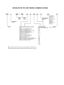


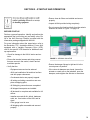

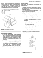


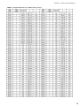
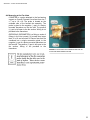
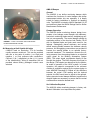
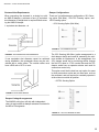
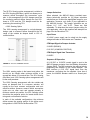
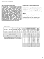


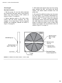
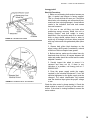
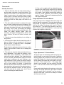
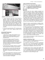

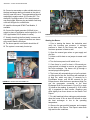
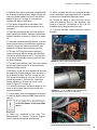
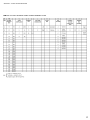
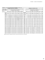
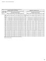
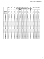
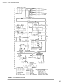

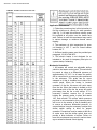


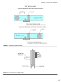
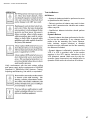

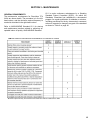
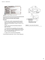


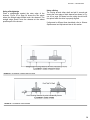
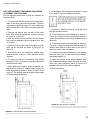
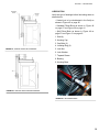
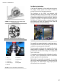


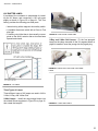


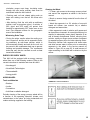
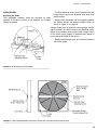

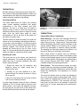
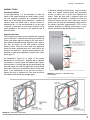

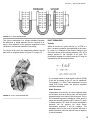

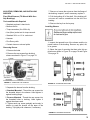
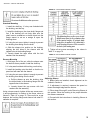

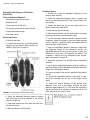


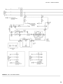

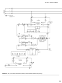
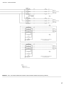
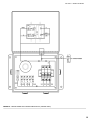


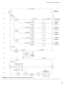
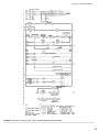
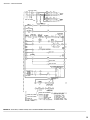

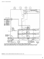
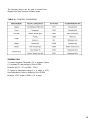
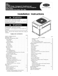


![v .] jCg _ 1l(_ `o,C..NN EinCOR `1_11E1](http://vs1.manualzilla.com/store/data/005961751_1-73960e1521729271050e00b8575619b8-150x150.png)