1
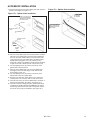
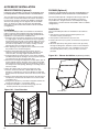
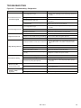
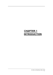
AIR 2-501.1
5H1041900001
November, 2013
INSTALLATION AND SERVICE MANUAL
Classmate®
Single Package Vertical Unit
Models CMD and CMP
WARNING
This unit contains R-410A high pressure refrigerant.
Hazards exist that could result in personal injury
or death. Installation, maintenance, and service
must only be performed by an HVAC technician
qualified in R-410A refrigerant and using proper
tools and equipment. Due to much higher pressure
of R-410A refrigerant, DO NOT USE service
equipment or tools designed for refrigerants other
than R410A.
IMPORTANT
WARNING
Improper installation, adjustment, alteration,
service or maintenance can cause property
damage, injury or death, and could cause
exposure to substances which have been
determined by various state agencies to cause
cancer, birth defects or other reproductive harm.
Read the installation, operating and maintenance
instructions thoroughly before installing or
servicing this equipment.
1. The use of this manual is specifically intended
for a qualified installation and service agency.
A qualified installation and service agency must
perform all installation and service of these
appliances.
2. CMD/P units contain the refrigerant R-410A.
Review the R-410A Material Safety Data Sheet
(MSDS) for hazards and first aid measures.
3. Refrigerant charging should only be carried out
by an EPA-certified air conditioning contractor.
Inspection On Arrival
1. Inspect unit upon arrival. In case of damage, report it
immediately to transportation company and your local factory
sales representative.
2.Check rating plate on unit to verify that power supply meets
available electric power at point of installation.
3. Inspect
unit received for conformance with description of
product ordered (including specifications where applicable).
THIS MANUAL IS THE PROPERTY OF THE OWNER.
PLEASE BE SURE TO LEAVE IT WITH the owner WHEN YOU LEAVE THE JOB.
SPECIAL PRECAUTIONS
SPECIAL PRECAUTIONS
THE INSTALLATION AND MAINTENANCE INSTRUCTIONS
IN THIS MANUAL MUST BE FOLLOWED TO PROVIDE
SAFE, EFFICIENT, AND TROUBLE-FREE OPERATION. IN
ADDITION, PARTICULAR CARE MUST BE EXERCISED
REGARDING THE SPECIAL PRECAUTIONS LISTED BELOW.
FAILURE TO PROPERLY ADDRESS THESE CRITICAL
AREAS COULD RESULT IN PROPERTY DAMAGE OR LOSS,
PERSONAL INJURY, OR DEATH. THESE INSTRUCTIONS
ARE SUBJECT TO ANY MORE RESTRICTIVE LOCAL OR
NATIONAL CODES.
HAZARD INTENSITY LEVELS
1. DANGER: Indicates an imminently hazardous situation
which, if not avoided, WILL result in death or serious injury.
2. WARNING: Indicates a potentially hazardous situation which,
if not avoided, COULD result in death or serious injury.
3. CAUTION: Indicates a potentially hazardous situation which,
if not avoided, MAY result in minor or moderate injury.
4. IMPORTANT: Indicates a situation which, if not avoided, MAY
result in a potential safety concern.
DANGER
Appliances must not be installed where they may be exposed to
potentially explosive or flammable atmosphere.
WARNING
1. Ensure
that the supply voltage to the appliance, as
indicated on the serial plate, is not 5% less than the rated
voltage.
2.U
nits not approved for use in potable water systems.
3. H
ot water supplied to the hot water heating option must
not exceed 200°F temperature or 125 PSIG pressure.
4. D
o not overcharge the refrigeration system. This can lead
to elevated compressor discharge pressure and possibly
flooding the compressor with liquid.
5. D
o not attempt to reuse any mechanical or electrical
component which has been wet. Such component must
be replaced.
important
1. S
tart-up and adjustment procedures should be performed
by a qualified service agency.
2. All refrigeration checks must be made by a qualified
R-410A refrigeration technician.
3. D
o not release refrigerant to the atmosphere. When
adding or removing refrigerant, all national, state/
province, and local laws must be followed.
4. To check most of the Possible Remedies in the
troubleshooting guide listed in Tables 22.1 and 23.1, refer
to the applicable sections of the manual.
Table of Contents
1. Disconnect power supply before making wiring
connections to prevent electrical shock and equipment
damage.
2. All appliances must be wired strictly in accordance with
the wiring diagram furnished with the appliance. Any
wiring different from the wiring diagram could result in a
hazard to persons and property.
3. Any original factory wiring that requires replacement must
be replaced with wiring material having a temperature
rating of at least 105°C.
4. Ensure that the supply voltage to the appliance, as
indicated on the serial plate, is not 5% greater than rated
voltage.
5. This unit contains R-410A high pressure refrigerant.
Hazards exist that could result in personal injury or
death. Installation, maintenance, and service must only
be performed by an HVAC technician qualified in R-410A
refrigerant and using proper tools and equipment. Due
to much higher pressure of R-410A refrigerant, DO NOT
USE service equipment or tools designed for refrigerants
other than R410A.
6. When servicing or repairing this equipment, use only
factory-approved service replacement parts. A complete
replacement parts list may be obtained by contacting
Modine Manufacturing Company. Refer to the rating plate
on the appliance for complete appliance model number,
serial number, and company address. Any substitution of
parts or controls not approved by the factory will be at the
owner’s risk.
2
CAUTION
General Information . . . . . . . . . . . . . . . . . . . . . . . . . . . . . . . . . . 1
Inspection on Arrival . . . . . . . . . . . . . . . . . . . . . . . . . . . . . . . . . 1
Special Precautions . . . . . . . . . . . . . . . . . . . . . . . . . . . . . . . . . . 2
SI (Metric) Conversion Factors . . . . . . . . . . . . . . . . . . . . . . . . . 3
Unit Location . . . . . . . . . . . . . . . . . . . . . . . . . . . . . . . . . . . . . . . 3
Installation . . . . . . . . . . . . . . . . . . . . . . . . . . . . . . . . . . . . . . . . 3
W
iring/Terminal Strip Connections . . . . . . . . . . . . . . . . . . . . 4
Start-Up Procedure
General . . . . . . . . . . . . . . . . . . . . . . . . . . . . . . . . . . . . . . . . . 5
Supplemental Heat (Optional) . . . . . . . . . . . . . . . . . . . . . . . 5
Dehumidification (Optional) . . . . . . . . . . . . . . . . . . . . . . . . . 5
Energy Recovery Ventilator (Optional) . . . . . . . . . . . . . . . . . 5
Start-Up Sheet – Examples . . . . . . . . . . . . . . . . . . . . . . . . . . 6-7
Unit Dimensions . . . . . . . . . . . . . . . . . . . . . . . . . . . . . . . . . . . . 8
Performance Data . . . . . . . . . . . . . . . . . . . . . . . . . . . . . . . . . . . 9
Technical Data . . . . . . . . . . . . . . . . . . . . . . . . . . . . . . . . . . . . . 10
Electrical Data . . . . . . . . . . . . . . . . . . . . . . . . . . . . . . . . . . 11-14
Component Layout . . . . . . . . . . . . . . . . . . . . . . . . . . . . . . . . . 15
Accessory Installation
Wall Sleeve and Louver . . . . . . . . . . . . . . . . . . . . . . . 16-17
Rear Extension . . . . . . . . . . . . . . . . . . . . . . . . . . . . . . . . . 18
Plenum . . . . . . . . . . . . . . . . . . . . . . . . . . . . . . . . . . . . . . . 18
Duct Shroud and Filler Panel . . . . . . . . . . . . . . . . . . . . . . 19
Maintenance . . . . . . . . . . . . . . . . . . . . . . . . . . . . . . . . . . . . . . 20
Replacement Parts . . . . . . . . . . . . . . . . . . . . . . . . . . . . . . 21
Model Nomenclature . . . . . . . . . . . . . . . . . . . . . . . . . . . . . 21
Serial Plate – Example . . . . . . . . . . . . . . . . . . . . . . . . . . . 21
Troubleshooting . . . . . . . . . . . . . . . . . . . . . . . . . . . . . . . . . 22-23
Warranty . . . . . . . . . . . . . . . . . . . . . . . . . . . . . . . . . . . . . . . . . 24
AIR 2-501
unit location / installation
Electrical
Table 3.1 - SI (Metric) Conversion Factors
To Convert Multiply By To Obtain
"W.C.
0.24
kPa
psig
6.893
kPa
°F (°F-32) x 0.555°C
inches
25.4
mm
feet
0.305 meters
CFM
0.028
m3/min
To Convert Multiply By To Obtain
CFH
1.699 m3/min
Btu/ft3 0.0374mJ/m3
pound
0.453
kg
Btu/hr 0.000293 kW/hr
gallons
3.785
liters
psig
27.7
"W.C.
unit location
DANGER
Appliances must not be installed where they may be exposed to
potentially explosive or flammable atmosphere.
Electrical wiring should be done in accordance with all
applicable national and local codes. It is the responsibility of the
electrical contractor to adhere to such codes. The warranty will
be voided if wiring is not in accordance with the specifications of
the unit. Modine recommends using copper conductors only.
All power supply wiring must be capable of carrying the
maximum current load under no fault conditions at the stipulated
voltages. Care should be taken to avoid significant voltage
drops.
A 1.5" diameter knockout for power connection is provided at
the top of the unit. Each unit is supplied with a 3 ft. power lead
extension for field connection to the customer supplied junction
box. This lead is connected directly into the unit’s electrical
panel.
INSTALLATION
Handling
Each unit will be shipped to the site on a wood skid. Whenever
possible, all lifting and handling of the unit should be done with
the packing and skid in position.
When slinging or using a forklift to lift the unit, the support points
should be sufficiently apart to give stability when lifting. Unless
otherwise noted, the lifting points should be equidistant from the
centerline. Extreme care should be taken not to drop the unit
Considerable damage can occur to the unit during positioning,
in particular, to the paneling and exterior paint. Use an adequate
number of personnel and the correct tools when moving the unit.
The unit is designed to remain upright so care should be taken
when lifting the unit up steps.
The use of torque screwdrivers on panel, cover or component
mounting screws is not recommended. Hand-start all screws.
If electric drills are used – set at the lowest possible torque.
Preparation
1. Before installation, ensure that the correct electrical power
supply is available for the unit.
2. Each unit requires an independently fused and isolated power
supply.
3. If the installation has multiple units, check that unit
identifications correspond with the network diagrams. Advise
Modine immediately if discrepancies are noted.
4. Check to make sure that the units will have adequate
installation clearance around them.
5. Note that each unit has a condensate connection at the
rear and suitable provisions should be made for draining. If
multiple units tee into a common drain manifold, the drain
line must be sized to ensure free draining with all the units in
operation.
6. Inspect the wall sleeve installation for gaps that would allow
leakage of outdoor air into the space. All joints and abutments
should be sealed with waterproof sealant.
The instructions detailed below are for the Installation of a
“Standard” unit. Accommodations and adjustments will be
required for the usage of additional unit accessories. Should
assistance be required for the installation of these additional
items, consult Modine at the phone number listed on the back
cover of this manual.
1. C
heck the floor for levelness and check to ensure the wall is
at a right angle to the floor. Should there be any irregularity,
the placement of foam tape on the outside edges of the unit
will fill the gaps between the unit and the wall, allowing for the
use of a sealant, to create a smooth transition from the unit to
the wall.
2. After adjusting for any irregularity in the location site, locate
the position for the floor mounting bolts (see figure 8.1). Drill
the appropriate sized holes, for the fasteners that are to be
utilized, and insert the anchors that are to be used.
3. R
emove the backing strip from the gasket on the wall sleeve.
Place the unit in the correct location, ensuring a tight seal with
the wall sleeve and the wall.
4. C
heck to ensure that the unit is plumb and level in both
directions. If adjustment is necessary, Modine recommends
the placement of metal shims in the outer most corners of the
base.
5. The cabinet must be secured to either the back wall or the
floor. The floor of the cabinet has four pre-punched holes and
the back of the cabinet has a hole on each side. The type of
materials used for the floor and the walls will determine the
type of fastener to use. Modine recommends the use of 1/2"
diameter fasteners with 1-1/2" diameter washers. Securing
the cabinet to the floor or wall helps to reduce movement and
noise due to vibration.
6. M
ake the condensate drain connection and the necessary
electrical connections to the unit.
7. W
hen connecting a duct flange or ductwork directly to the top
of the unit, do not drill or put screws into the area immediately
surrounding the supply air opening(s). See Figure 4.1
(dimensions in inches). Holes in the top of the cabinet
indicate recommended mounting locations.
Drainage
Each unit has an internal condensate drain, terminating
internally to the unit. A 1-3/8" condensate drain hole is available
on the back side of the unit (see Figure 9.1 for the location).
This must be connected to the main drain system in accordance
with any local codes and general good piping practice.
AIR 2-501
3
installation
Installation of wiring must conform with local building codes,
or in the absence of local codes, with the National Electric
Code ANSI/NFPA 70 - Latest Edition. Unit must be electrically
grounded in conformance to this code. In Canada, wiring must
comply with CSA C22.1, Part 1, Electrical Code.
Figure 4.1 - Do Not Drill Zone
SIZE 24 / 36
15.00
11.00
“DO NOT DRILL”
ZONE
8.75
Electric wiring must be sized to carry the full load amp draw of
the motor, starter and any controls that are used with the unit.
See Tables 11.1-14.1 for electrical data.
Any damage to or failure of units caused by incorrect wiring of
the units is not covered by warranty.
The electrical supply can be connected to the unit power lead
extension at a customer supplied junction box.
When installing any wiring into the electrical panel, extra cable
must be left outside the panel to allow the panel to open fully.
Failure to follow these instructions may cause damage to the
wiring and/or the unit.
SIZE 48 / 60
12.50
8.75
16.00
“DO NOT DRILL”
ZONE
Terminal Strip Connections
The terminal strip connections are designed to clamp down on
the wires. To properly connect the wires to the terminal strip:
1. P
ush a small flat-head screwdriver into the square hole on the
terminal. Press firmly until the screwdriver hits the back stop
and opens the terminal (see Figure 4.2).
2. R
emove approximately 3/8" of insulation from the end of
the wire and push the stripped wire into the oval hole in the
terminal.
3. R
emove the screwdriver. Pull on the wire to make sure that it
is securely clamped in the terminal.
4. M
ake sure that the terminal clamp is in contact with bare wire
(insulation removed).
Wiring
WARNING
Figure 4.2 - Terminal Strip
1. Disconnect power supply before making wiring
connections to prevent electrical shock and equipment
damage.
2. All appliances must be wired strictly in accordance with
the wiring diagram furnished with the appliance. Any
wiring different from the wiring diagram could result in a
hazard to persons and property.
3. Any original factory wiring that requires replacement must
be replaced with wiring material having a temperature
rating of at least 105°C.
4. Ensure that the supply voltage to the appliance, as
indicated on the serial plate, is not 5% greater than rated
voltage.
CAUTION
Ensure that the supply voltage to the appliance, as indicated
on the serial plate, is not 5% less than the rated voltage.
4
AIR 2-501
START-UP PROCEDURE
start-uP procedure
important
Start-up and adjustment procedures should be performed by
a qualified service agency.
Fan: The fan will run continuously during occupied mode
and will be intermittent on a call for cooling or heating during
unoccupied mode. A built in fan purge time allows for maximum
heating and cooling efficiency.
Cool: When the temperature increases above the cooling
setpoint, the compressor and reversing valve will be energized.
The compressor will be limited to the number of starts per hour
by anti-cycle protection.
Heat: When the temperature falls below the heating setpoint,
the compressor will be energized and the reversing valve
de-energized. The compressor will be limited to the number of
starts per hour by anti-cycle protection.
The unit has been factory tested and set for proper operation,
but a full unit start-up is recommended.
See start-up sheet examples - Figures 6.1 and 7.1
Pre-Start Checks
1. Check that the supply voltage matches the unit supply voltage
listed on the Unit Serial Plate. Verify that all wiring is secure
and properly protected. Trace circuits to insure that the unit
has been wired according to the wiring diagram.
2. Check that the unit has no visible damage and that all the
components are secure.
3. Check that all field electrical and mechanical work has been
performed according to all applicable Federal, State, and
Local codes.
4. Check the supply voltage to the unit is within +/- 5% of the
voltage on the unit serial plate.
Unit Start-Up Procedure
1. Disconnect and cap the wires to the CP1 contactor coil. This
will allow the compressor crankcase heater to operate without
the compressor operating. It is necessary to allow at least
4 hours of compressor crankcase heater operation before
energizing the compressor.
2. Turn the disconnect switch to the “ON” position.
3. After the 4 hour compressor crankcase heater operation time,
reconnect the CP1 contactor coil wires.
4. Follow the instructions in the Modine microprocessor book.
The control parameters and setpoints have all been factory
set to the default values.
5. During the unit operation, measure and record all the
information that is required to complete the Start-Up Sheets
that are supplied with the unit. Copy the information onto the
Start-Up Sheets (Figures 6.1 and 7.1) in this manual for your
records.
Supplemental Heat (Optional): If the temperature falls below
the second stage heat setpoint, supplementary heat (if installed:
electric heaters, hot water or steam coil) will be energized. If two
stages of electric heat are fitted, the second stage will only be
enabled if the compressor is locked out on its safety devices. If
the unit is fitted with a hot water coil the valve will be a normally
open type.
Dehumidification (Optional): The unit can be fitted with
a humidity sensor to control the humidity level in the room.
When the humidity increases above an adjustable setpoint,
the compressor and reversing valves are energized. A hot gas
reheat coil is turned on using the hot gas from the compressor
to re-heat the supply air.
Energy Recovery Ventilator (Optional): During operation
when the unit is cooling the room (summer), cool room return air
is drawn across the enthalpy wheel. This air is then exhausted
external to the room. Warm, humid ambient air is drawn across
the other side of the ERV and as the enthalpy wheel turns, the
air is cooled and dehumidified. This air is then mixed with the
room air and recirculated through the indoor section.
During operation when the unit is heating the room (winter) the
warm, moist air from the room is used to temper the cold, dry
external ambient air.
Table 5.1 - Refrigerant Charge
Charge (lbs of R-410A)
Nominal
Capacity
CMD
CMP
24
9.38
9.00
36
9.75
11.00
Sequence of Operation
48
11.50
12.00
Microprocessor: A Carel microprocessor will control the
unit and allow for networking and remote monitoring. The
microprocessor will monitor the room temperature (either via
an optional wall thermostat or return air sensor), supply air and
outdoor air. With this information the unit is able to operate at
maximum efficiency. The occupied/unoccupied control can be
via time clock or from a signal from a building central time clock.
60
11.00
11.75
If a wall or unit mounted thermostat is selected, the setpoint can
be either fully adjustable or +/- three degrees. This allows some
control of the room temperature while limiting its adjustment.
The thermostat will also have an occupied override button to
allow a temporary override until the next scheduled occupancy
change.
Please reference Modine Controls System Manual (AIR 2-525)
and Quickstart (AIR 2-526) literature pieces for assistance in
starting up units configured with Modine Control Systems.
AIR 2-501
5
start-up sheet - example
Figure 6.1 - Start-Up Sheet - EXAMPLE Page 1
Modine Manufacturing Company – ClassMate Start-up Sheet
This document should be returned to Airedale within 30 days of start-up to validate warranty
Date
Job Reference
TAG ID
Serial #
Unit Type
SPO #
Drawing #
Installer
Sales Rep
Room ID
Installation Checks
Unit Mounted Level
Unit Bolted to Floor or Wall
Condensate Drain Installed Correctly
Transition / Wall Sleeve Installed Correctly
Transition / Wall Sleeve Insulated
Splitter Plate Fitted Correctly
Electrical and Mechanical Connections all Tight
Any Visual Damage to the Unit
Indoor Fan (ECM)
Motor Size
(hp)
FLA
Amps
High
Med
Low
+15%
-15%
Program
Outdoor Fan (ECM)
Motor Size
(hp)
FLA
Make
Amps
Low
Taps @ Hi
High
Compressor
Compressor Model
Make
RLA
Make
Cool Stage 3
100%
L1 Amps
L2 Amps
Cool Stage 1
67%
L1 Amps
L2 Amps
L3 Amps
Heat Stage 3
100%
L1 Amps
L2 Amps
L3 Amps
Heat Stage 1
67%
L1 Amps
L2 Amps
L3 Amps
Mains Incoming Voltage
L1+L2
Transformer Voltage
Refrigeration
Cooling
100%
L2+L3
L3+L1
Primary
Secondary
Cooling
67%
L3 Amps
Heat pump
100%
Heat pump
67%
Suction Pressure
Discharge Pressure
Superheat
Hot Gas Valve Setting
Operational Temperatures
Cooling
Heat pump
Return Air Temperature
ºF
ºF
Supply Air Temperature
ºF
ºF
Outside Air Temperature
ºF
ºF
Indoor Coil Temperature
ºF
ºF
Outdoor Coil Temperature
ºF
ºF
1
07/11/2013
6
AIR 2-501
start-up sheet - example
Figure 7.1 - Start-Up Sheet - EXAMPLE Page 2
Modine Manufacturing Company – ClassMate Start-up Sheet
This document should be returned to Airedale within 30 days of start-up to validate warranty
Control Transformer Voltages
Primary
Controller information
Make
Secondary
Model
Address / Outstation
Network Card
Program Revision
SPID
Occupied Set points
Neuron ID
Unoccupied Set points
Stat Model
Economizer Assembly
Build and Operation Correct
Heat Recovery Wheel Section
Heat Recovery Wheel Motor
FLA
RLA
Heat Wheel Fan Motor 1
FLA
RLA
Heat Wheel Fan Motor 2
FLA
RLA
Hot Water / Steam Valve
Build and Operation Correct
Electric Heating
Stage 1 Amps
L1
L2
L3
Stage 2 Amps
L1
L2
L3
Freeze Protection Stat
Manual or Auto Reset
Stat setting
ºF
Stat operation correct
Technicians Notes:
Customer Feed Back: Please relay any comments about Quality or Service
Service Technician
Service Company
Service Company Telephone
AIR 2-501
7
dimensions
Figure 8.1 - Dimensions - Base Unit CMD & CMP
TOP
B
A
C
SUPPLY AIR
OUTLET
9.40
MOUNTING HOLES FOR
PLENUMS OR SHROUDS
2 X O 1.5 ELECTRICAL
SUPPLY ENTRANCE
16.35
11.46 7.60
4.00
6.43
9.32
6.00
2 X O 1.27
HOT WATER CONNECTIONS
30.00
FRONT
SIDE
90.00
REAR
D
RETURN
AIR
INLET
x2
E
6.00
OUTSIDE AIR IN
7.05
OUTSIDE AIR IN
F
1.00
49.84
G
EXHAUST AIR
OUT
3.25
2.50
35.75
10.30
9.13
O 1.31
CONDENSATE DRAIN LINE
2.54
4 HOLES O.100
BASE FIXING
POSITION
10.32
6.00
10.32
12.84
12.84
6.00
Table 8.1 - Unit Dimensions
Dimensions (inches)
Model
Size
A
B
C
D
E
F
G
24/36
42.00
13.70
10.52
7.30
31.00
40.00
25.12
48/60
48.00
15.70
13.12
6.30
37.00
46.00
31.12
6.00
RETURN AIR
INLET
BASE
8
AIR 2-501
performance data
Table 9.1 - Performance Data - CMD
CMD (Rated in accordance with AHRI 390)
Units 24
36
48
60
MBH
24.4
34.0
46.8
56.0
Full Load Cooling (80/67˚F Air On, 95/75˚F Outdoor)
Total Cooling
Sensible Cooling
EER
Rated Airflow
MBH
17.5
24.3
31.5
37.0
MBH/KW
12.1
11.0
11.6
9.7
CFM
900
1100
1500
1800
MBH
17.1
27.3
37.1
43.4
Part Load Cooling (80/67˚F Air On, 80/67˚F Outdoor)
Total Cooling
Sensible Cooling
MBH
11.1
19.3
24.9
29.8
MBH/KW
14.1
14.4
16.1
11.6
CFM
700
800
1100
1500
Units 24
36
48
60
Total Cooling
MBH
22.0
33.5
45.2
52.7
Sensible Cooling
MBH
17.0
24.0
32.2
37.6
MBH/KW
11.2
10.5
11.0
9.0
CFM
900
1100
1500
1800
Total Heating
MBH
20.9
32.8
47.2
58.8
COP
W/W
3.4
3.7
4.0
3.6
Rated Airflow
CFM
900
1100
1500
1800
Total Cooling
MBH
18.0
26.7
36.8
43.8
Sensible Cooling
MBH
14.6
19.1
26.0
33.4
MBH/KW
15.6
14.3
15.4
11.6
CFM
700
800
1100
1500
Total Heating
MBH
19.0
28.5
42.7
52.1
COP
W/W
4.6
4.2
4.4
4.3
Rated Airflow
CFM
700
800
1100
1500
IPLV
Rated Airflow
Table 11.2 - Performance Data - CMP
CMP (Rated in accordance with AHRI 390)
Full Load Cooling (80/67˚F Air On, 95/75˚F Outdoor)
EER
Rated Airflow
Full Load Heating (70/60˚F Air On, 47/43˚F Outdoor)
Part Load Cooling (80/67˚F Air On, 80/67˚F Outdoor)
IPLV
Rated Airflow
Part Load Heating (70/60˚F Air On, 62/56.5˚F Outdoor)
Table 11.3 - Performance Data - Energy Recovery Wheel (Optional)
ENERGY RECOVERY WHEEL (optional)
DATA SHOWN FOR ALL UNITS
Outdoor Air Volume
CFM
200
300
400
500
Total Capacity Recovered (Cooling) ➀
MBH
8.6
11.7
13.9
15.3
Measured Cooling Effectiveness
Total Capacity Recovered (Heating) ➁
Measured Heating Effectiveness
%
78.4
71.3
64.3
57.5
MBH
9.1
12.5
15.1
16.9
%
79.8
73.1
66.7
60.2
➀ Cooling capacity based on: Room 75/63˚F Dry/Wet Bulb, Ambient 95/78˚F Dry/Wet Bulb. ➁ Heating capacity based on: Room 70/58.5˚F Dry/Wet Bulb, Ambient 35/33˚F Dry/Wet Bulb.
AIR 2-501
9
TECHNICAL DATA
Table 10.1 - Technical Data - CMD & CMP
DIMENSIONS – (H x W x D)
IN
INDOOR (Evaporator) COIL - Face Area
IN2
720
720
863
863
OUTDOOR (Condenser) COIL - Face Area
IN2
952
952
1156
1156
90 X 42 X 30
SUPPLY FAN
90 X 48 X 30
Direct Drive Centrifugal
Fan Quantity
1
Motor Size (Qty 1)
HP
1/2
Motor Type
1
1
1
1/2
1
1
Electronically Commutated Motor (ECM)
Indoor Coil Airflow
Rated/Max External Static Pressure
CFM
900
IN.Wg
0.10/0.50
EXHAUST FAN
1,100
1,500
1,800
0.15/0.50
0.20/0.50
0.20/0.50
Backward Curved Motorized Impellor
Fan Quantity
OutdoorCoil Airflow
CFM
1
1
1
1
2100
2100
2800
3000
Motor Type
Electronically Commutated Motor (ECM)
Max Room Exhaust Airflow
Rated/Max External Static Pressure
CFM
900
1,100
1,500
1,800
IN.Wg
0.10/0.50
0.15/0.50
0.20/0.50
0.20/0.50
COMPRESSOR
Copeland Scroll ULTRATECH
Stages
0, 67%, 100%
Refrigerant Type
HFC-R410A
UNIT WEIGHT
Operating Weight
LBS.
685
FILTER
735
765
830
MERV 8,11,13,16
Quantity
Dimensions
2
2
2
2
IN
16 x 25
16 x 25
20 x 25
20 x 25
KW
20
20
20
20
2
2
2
2
MBH
70/82
74/88
82/101
87/111
ELECTRIC HEATING (optional)
Electric Heating Capacity
Stages
HOT WATER HEATING (optional)
Factory Installed - 1 row
Factory Installed - 2 row
Plenum Mounted - 1 row
Plenum Mounted - 2 row
Heating Capacity - 3/6 GPM ➀
Water Pressure Drop - 3/6 GPM
Heating Capacity - 3/6 GPM ➀
Water Pressure Drop - 3/6 GPM
Heating Capacity - 3/6 GPM ➀
Water Pressure Drop - 3/6 GPM
Heating Capacity - 3/6 GPM ➀
Water Pressure Drop - 3/6 GPM
PSI
0.37/1.23
0.37/1.23
0.37/1.23
0.37/1.23
MBH
94/106
101/118
113/139
122/158
PSI
0.75/2.50
0.75/2.5
0.88/2.94
0.88/2.94
MBH
71/83
78/94
82/102
84/106
PSI
0.45/1.50
0.45/1.50
0.45/1.50
0.45/1.50
MBH
93/107
104/126
109/139
111/146
PSI
0.13/0.44
0.13/0.44
0.13/.44
0.13/0.44
MBH
93/97
103/108
116/122
124/131
STEAM HEATING (optional)
Plenum Mount
1 Row Heating Capacity - 2/5 psig ➀
➀ Hot water/steam heating capacity based on an Air On 33˚F (24MBH), 38˚F (36MBH), 47˚F (4Ton), and 51˚F (5 Ton). The Air On based on 450 CFM outside air at 0˚F and
70˚F room ambient for 24 MBH unit, and 500 CFM outside air at 0˚F and 70˚F room ambient for 36, 48, and 60 MBH unit. For Hot Water: Entering water temperature
180˚F, and water flow rate of 3 and 6 GPM. For Steam: Steam pressure of 2 and 5 psig.
10
AIR 2-501
electrical data
Table 11.1 - Electrical Data
Model
CMD
24
CMD
36
CMD
48
CMD
60
Model
CMD
24
CMD
36
CMD
48
CMD
60
Voltage
208V/1Ph
230V/1Ph
208V/3Ph
230V/3Ph
460V/3Ph
575V/3Ph
277V/1Ph
208V/1Ph
230V/1Ph
208V/3Ph
230V/3Ph
460V/3Ph
575V/3Ph
277V/1Ph
208V/1Ph
230V/1Ph
208V/3Ph
230V/3Ph
460V/3Ph
575V/3Ph
277V/1Ph
208V/1Ph
230V/1Ph
208V/3Ph
230V/3Ph
460V/3Ph
575V/3Ph
277V/1Ph
Voltage
208V/1Ph
230V/1Ph
208V/3Ph
230V/3Ph
460V/3Ph
575V/3Ph
277V/1Ph
208V/1Ph
230V/1Ph
208V/3Ph
230V/3Ph
460V/3Ph
575V/3Ph
277V/1Ph
208V/1Ph
230V/1Ph
208V/3Ph
230V/3Ph
460V/3Ph
575V/3Ph
277V/1Ph
208V/1Ph
230V/1Ph
208V/3Ph
230V/3Ph
460V/3Ph
575V/3Ph
277V/1Ph
BASE UNIT
2kW
3kW
5kW
6kW
7.5kW
MCA FLA MOP MCA FLA MOP MCA FLA MOP MCA FLA MOP MCA FLA MOP MCA FLA MOP
24.1 21.2
35
24.1 21.2
35
28.6 22.9
35
39.8 31.9
40
45.4 36.3
50
53.8 43.0
60
23.0 20.1
30
23.0 20.1
30
29.0 23.2
30
41.4 33.1
45
47.6 38.1
50
56.8 45.5
60
17.6 16.0
20
18.3 16.0
20
21.6 17.2
25
28.0 22.4
30
31.2 25.0
35
36.1 28.9
40
16.5 14.9
20
17.6 14.9
20
21.2 17.0
25
28.3 22.7
30
31.9 25.5
35
37.3 29.8
40
8.5
7.6
15
8.7
7.6
15
10.5 8.4
15
15.8 12.6
20
15.9 12.7
20
18.5 14.8
20
18.6
28.6
27.5
24.0
22.9
11.2
8.4
23.5
39.3
37.9
30.3
28.9
13.6
10.3
29.7
46.7
45.3
33.4
32.0
14.6
11.5
37.7
16.3
24.8
23.7
21.1
20.0
9.8
7.4
20.2
34.0
32.6
26.8
25.4
12.0
9.2
25.7
39.9
38.5
29.3
27.9
12.8
10.1
32.1
MCA
62.2
66.1
40.9
42.6
21.2
9kW
10kW
12kW
15kW
18kW
20kW
FLA MOP MCA FLA MOP MCA FLA MOP MCA FLA MOP MCA FLA MOP MCA FLA MOP
49.7
70
67.8 54.2
70
78.9 63.2
80
95.7 76.6 100
52.9
70
72.3 57.8
80
84.7 67.7
90 103.2 82.6 110
32.7
45
44.1 35.3
45
50.6 40.5
60
60.3 48.2
70
69.9 56.0
70
74.5 59.6
80
34.1
45
46.2 36.9
50
53.3 42.7
60
64.0 51.2
70
74.7 59.8
80
79.8 63.8
80
17.0
25
26.5 21.2
30
26.6 21.3
30
31.9 25.6
35
37.3 29.8
40
40.9 32.7
45
59.4
62.2
66.1
40.9
42.6
21.2
17.0
59.4
66.3
69.9
45.0
46.4
23.1
18.5
62.6
66.3
69.9
45.0
46.4
23.1
18.5
62.6
47.6
49.7
52.9
32.7
34.1
17.0
13.6
47.6
53.0
55.9
36.0
37.1
18.5
14.8
50.1
53.0
55.9
36.0
37.1
18.5
14.8
50.1
MOP = Maximum Overcurrent Protection
25
40
40
35
30
15
15
35
60
50
40
40
20
15
45
70
70
45
45
20
15
60
60
70
70
45
45
25
20
60
70
70
50
50
25
20
70
70
70
50
50
25
20
70
20.2
28.6
27.5
24.0
22.9
11.2
8.4
23.5
39.3
37.9
30.3
28.9
13.6
10.3
29.7
46.7
45.3
33.4
32.0
14.6
11.5
37.7
65.1
67.8
72.3
44.1
46.2
26.5
18.4
65.1
71.9
76.1
48.3
49.9
28.3
19.9
68.2
71.9
76.1
48.3
49.9
28.3
19.9
68.2
16.3
24.8
23.7
21.1
20.0
9.8
7.4
20.2
34.0
32.6
26.8
25.4
12.0
9.2
25.7
39.9
38.5
29.3
27.9
12.8
10.1
32.1
52.1
54.2
57.8
35.3
36.9
21.2
14.7
52.1
57.5
60.8
38.6
39.9
22.7
15.9
54.6
57.5
60.8
38.6
39.9
22.7
15.9
54.6
25
40
40
35
30
15
15
35
60
50
40
40
20
15
45
70
70
45
45
20
15
60
70
70
80
45
50
30
20
70
80
80
50
50
30
20
70
80
80
50
50
30
20
70
25.8
28.6
29.0
24.0
22.9
11.2
8.5
25.8
39.3
37.9
30.3
28.9
13.6
10.3
29.7
46.7
45.3
33.4
32.0
14.6
11.5
37.7
76.3
78.9
84.7
50.6
53.3
26.6
21.3
76.3
83.1
88.4
54.7
57.1
28.5
22.8
79.4
83.1
88.4
54.7
57.1
28.5
22.8
79.4
MCA = Minimum Circuit Ampacity
20.7
24.8
23.7
21.1
20.0
9.8
7.4
20.7
34.0
32.6
26.8
25.4
12.0
9.2
25.7
39.9
38.5
29.3
27.9
12.8
10.1
32.1
61.0
63.2
67.7
40.5
42.7
21.3
17.0
61.0
66.5
70.7
43.8
45.7
22.8
18.2
63.5
66.5
70.7
43.8
45.7
22.8
18.2
63.5
30
40
40
35
30
15
15
35
60
50
40
40
20
15
45
70
70
45
45
20
15
60
80
80
90
60
60
30
25
80
90
90
60
60
30
25
80
90
90
60
60
30
25
80
37.0
39.8
41.4
28.0
28.3
15.8
11.3
37.0
43.9
45.2
32.1
32.1
17.7
12.8
40.2
46.7
45.3
33.4
32.1
17.7
12.8
40.2
93.1
95.7
103.2
60.3
64.0
31.9
25.5
93.1
99.8
106.9
64.4
67.8
33.8
27.0
96.2
99.8
106.9
64.4
67.8
33.8
27.0
96.2
29.6
31.9
33.1
22.4
22.7
12.6
9.1
29.6
35.2
36.1
26.8
25.7
14.1
10.3
32.1
39.9
38.5
29.3
27.9
14.1
10.3
32.1
74.5
76.6
82.6
48.2
51.2
25.6
20.4
74.5
79.9
85.6
51.5
54.2
27.1
21.6
77.0
79.9
85.6
51.5
54.2
27.1
21.6
77.0
40
40
45
35
30
20
15
40
60
50
40
40
20
15
45
70
70
45
45
20
15
60
100
100
110
70
70
35
30
100
100
110
70
70
35
30
100
100
110
70
70
35
30
100
42.6
45.4
47.6
31.2
31.9
15.9
12.8
42.6
49.5
51.3
35.4
35.7
17.7
14.3
45.8
49.5
51.3
35.4
35.7
17.7
14.3
45.8
34.1
36.3
38.1
25.0
25.5
12.7
10.2
34.1
39.6
41.1
28.3
28.5
14.2
11.4
36.6
39.9
41.1
29.3
28.5
14.2
11.4
36.6
45
50
50
35
35
20
15
45
60
60
40
40
20
15
50
70
70
45
45
20
15
60
51.1
53.8
56.8
36.1
37.3
18.5
14.9
51.1
57.9
60.6
40.2
41.0
20.4
16.4
54.2
57.9
60.6
40.2
41.0
20.4
16.4
54.2
40.8
43.0
45.5
28.9
29.8
14.8
11.9
40.8
46.3
48.5
32.2
32.8
16.3
13.1
43.3
46.3
48.5
32.2
32.8
16.3
13.1
43.3
60
60
60
40
40
20
15
60
60
70
45
45
25
20
60
70
70
45
45
25
20
60
69.9
74.7
37.3
29.8
56.0
59.8
29.8
23.8
70
80
40
30
74.5
79.8
40.9
32.6
59.6
63.8
32.7
26.1
80
80
45
35
74.1
78.5
39.2
31.3
59.3
62.8
31.3
25.0
80
80
40
35
78.6
83.5
42.8
34.1
62.9
66.8
34.2
27.3
80
90
45
35
74.1
78.5
39.2
31.3
59.3
62.8
31.3
25.0
80
80
40
35
78.6
83.5
42.8
34.1
62.9
66.8
34.2
27.3
80
90
45
35
FLA = Full Load Amps
AIR 2-501
11
electrical data
Table 12.1 - Electrical Data
Model
CMD
24
with
ERV
CMD
36
with
ERV
CMD
48
with
ERV
CMD
60
with
ERV
Model
CMD
24
with
ERV
CMD
36
with
ERV
CMD
48
with
ERV
CMD
60
with
ERV
Voltage
208V/1Ph
230V/1Ph
208V/3Ph
230V/3Ph
460V/3Ph
575V/3Ph
277V/1Ph
208V/1Ph
230V/1Ph
208V/3Ph
230V/3Ph
460V/3Ph
575V/3Ph
277V/1Ph
208V/1Ph
230V/1Ph
208V/3Ph
230V/3Ph
460V/3Ph
575V/3Ph
277V/1Ph
208V/1Ph
230V/1Ph
208V/3Ph
230V/3Ph
460V/3Ph
575V/3Ph
277V/1Ph
Voltage
208V/1Ph
230V/1Ph
208V/3Ph
230V/3Ph
460V/3Ph
575V/3Ph
277V/1Ph
208V/1Ph
230V/1Ph
208V/3Ph
230V/3Ph
460V/3Ph
575V/3Ph
277V/1Ph
208V/1Ph
230V/1Ph
208V/3Ph
230V/3Ph
460V/3Ph
575V/3Ph
277V/1Ph
208V/1Ph
230V/1Ph
208V/3Ph
230V/3Ph
460V/3Ph
575V/3Ph
277V/1Ph
BASE UNIT
2kW
3kW
5kW
6kW
7.5kW
MCA FLA MOP MCA FLA MOP MCA FLA MOP MCA FLA MOP MCA FLA MOP MCA FLA MOP
27.3 24.4
35
27.3 24.4
35
32.6 26.1
35
43.8 35.1
45
49.4 39.5
50
57.8 46.2
60
25.8 22.9
35
26.4 22.9
35
32.5 26.0
35
44.9 35.9
45
51.1 40.9
60
60.3 48.3
70
20.8 19.2
25
22.3 19.2
25
25.6 20.4
30
32.0 25.6
35
35.2 28.2
40
40.1 32.1
45
19.3 17.7
25
21.1 17.7
25
24.7 19.8
25
31.8 25.5
35
35.4 28.3
40
40.8 32.6
45
9.9
9.0
15
10.5 9.0
15
12.2 9.8
15
17.5 14.0
20
17.6 14.1
20
20.3 16.2
25
18.6
31.8
30.3
27.2
25.7
12.6
8.4
23.5
42.5
40.7
33.5
31.7
15.0
10.3
29.7
49.9
48.1
36.6
34.8
16.0
11.5
37.7
16.3
28.0
26.5
24.3
22.8
11.2
7.4
20.2
37.2
35.4
30.0
28.2
13.4
9.2
25.7
43.1
41.3
32.5
30.7
14.2
10.1
32.1
MCA
66.2
69.6
44.9
46.1
23.0
9kW
10kW
12kW
15kW
18kW
20kW
FLA MOP MCA FLA MOP MCA FLA MOP MCA FLA MOP MCA FLA MOP MCA FLA MOP
52.9
70
71.8 57.4
80
82.9 66.4
90
99.7 79.8 100
55.7
70
75.8 60.6
80
88.2 70.5
90 106.7 85.4 110
35.9
45
48.1 38.5
50
54.6 43.7
60
64.3 51.4
70
73.9 59.2
80
78.5 62.8
80
36.9
50
49.7 39.7
50
56.8 45.5
60
67.5 54.0
70
78.2 62.6
80
83.3 66.6
90
18.4
25
28.2 22.6
30
28.3 22.7
30
33.7 27.0
35
39.1 31.2
40
42.6 34.1
45
59.4
66.2
69.6
44.9
46.1
23.0
17.0
59.4
70.3
73.4
49.0
49.9
24.8
18.5
62.6
70.3
73.4
49.0
49.9
24.8
18.5
62.6
47.6
52.9
55.7
35.9
36.9
18.4
13.6
47.6
56.2
58.7
39.2
39.9
19.9
14.8
50.1
56.2
58.7
39.2
39.9
19.9
14.8
50.1
MOP = Maximum Overcurrent Protection
12
25
45
45
35
35
15
15
35
60
60
45
45
20
15
45
70
70
50
50
20
15
60
60
70
70
45
50
25
20
60
80
80
50
50
25
20
70
80
80
50
50
25
20
70
20.2
31.8
30.3
27.2
25.7
12.6
8.4
23.5
42.5
40.7
33.5
31.7
15.0
10.3
29.7
49.9
48.1
36.6
34.8
16.0
11.5
37.7
65.1
71.8
75.8
48.1
49.7
28.2
18.4
65.1
75.9
79.6
52.3
53.4
30.1
19.9
68.2
75.9
79.6
52.3
53.4
30.1
19.9
68.2
16.3
28.0
26.5
24.3
22.8
11.2
7.4
20.2
37.2
35.4
30.0
28.2
13.4
9.2
25.7
43.1
41.3
32.5
30.7
14.2
10.1
32.1
52.1
57.4
60.6
38.5
39.7
22.6
14.7
52.1
60.7
63.6
41.8
42.7
24.1
15.9
54.6
60.7
63.6
41.8
42.7
24.1
15.9
54.6
25
45
45
35
35
15
15
35
60
60
45
45
20
15
45
70
70
50
50
20
15
60
70
80
80
50
50
30
20
70
80
80
60
60
35
20
70
80
80
60
60
35
20
70
25.8
32.6
32.5
27.2
25.7
12.6
8.5
25.8
42.5
40.7
33.5
31.7
15.0
10.3
29.7
49.9
48.1
36.6
34.8
16.0
11.5
37.7
76.3
82.9
88.2
54.6
56.8
28.3
21.3
76.3
87.1
91.9
58.7
60.6
30.2
22.8
79.4
87.1
91.9
58.7
60.6
30.2
22.8
79.4
MCA = Minimum Circuit Ampacity
20.7
28.0
26.5
24.3
22.8
11.2
7.4
20.7
37.2
35.4
30.0
28.2
13.4
9.2
25.7
43.1
41.3
32.5
30.7
14.2
10.1
32.1
61.0
66.4
70.5
43.7
45.5
22.7
17.0
61.0
69.7
73.5
47.0
48.5
24.2
18.2
63.5
69.7
73.5
47.0
48.5
24.2
18.2
63.5
30
45
45
35
35
15
15
35
60
60
45
45
20
15
45
70
70
50
50
20
15
60
80
90
90
60
60
30
25
80
90
100
60
70
35
25
80
90
100
60
70
35
25
80
37.0
43.8
44.9
32.0
31.8
17.5
11.3
37.0
47.9
48.7
36.1
35.6
19.4
12.8
40.2
49.9
48.7
36.6
35.6
19.4
12.8
40.2
40
45
45
35
35
20
15
40
60
60
45
45
20
15
45
70
70
50
50
20
15
60
93.1
99.7
106.7
64.3
67.5
33.7
25.5
93.1
103.8
74.5
79.8
85.4
51.4
54.0
27.0
20.4
74.5
83.1
100
100
110
70
70
35
30
100
110
68.4
71.3
35.6
27.0
96.2
103.8
54.7
57.0
28.5
21.6
77.0
83.1
68.4
71.3
35.6
27.0
96.2
54.7
57.0
28.5
21.6
77.0
FLA = Full Load Amps
AIR 2-501
29.6
35.1
35.9
25.6
25.5
14.0
9.1
29.6
38.4
38.9
30.0
28.5
15.5
10.3
32.1
43.1
41.3
32.5
30.7
15.5
10.3
32.1
42.6
49.4
51.1
35.2
35.4
17.6
12.8
42.6
53.5
54.8
39.4
39.2
19.5
14.3
45.8
53.5
54.8
39.4
39.2
19.5
14.3
45.8
34.1
39.5
40.9
28.2
28.3
14.1
10.2
34.1
42.8
43.9
31.5
31.3
15.6
11.4
36.6
43.1
43.9
32.5
31.3
15.6
11.4
36.6
45
50
60
40
40
20
15
45
60
60
45
45
20
15
50
70
70
50
50
20
15
60
51.1
57.8
60.3
40.1
40.8
20.3
14.9
51.1
61.9
64.1
44.2
44.5
22.2
16.4
54.2
61.9
64.1
44.2
44.5
22.2
16.4
54.2
40.8
46.2
48.3
32.1
32.6
16.2
11.9
40.8
49.5
51.3
35.4
35.6
17.7
13.1
43.3
49.5
51.3
35.4
35.6
17.7
13.1
43.3
60
60
70
45
45
25
15
60
70
70
45
45
25
20
60
70
70
50
50
25
20
60
73.9
78.2
39.1
29.8
59.2
62.6
31.2
23.8
80
80
40
30
78.5
83.3
42.6
32.6
62.8
66.6
34.1
26.1
80
90
45
35
70
80
40
30
100
110
78.1
82.0
40.9
31.3
62.5
65.6
32.7
25.0
80
90
45
35
82.6
87.0
44.5
34.1
66.1
69.6
35.6
27.3
90
90
45
35
70
80
40
30
100
78.1
82.0
40.9
31.3
62.5
65.6
32.7
25.0
80
90
45
35
82.6
87.0
44.5
34.1
66.1
69.6
35.6
27.3
90
90
45
35
electrical data
Table 13.1 - Electrical Data
Model
CMP
24
CMP
36
CMP
48
CMP
60
Model
CMP
24
CMP
36
CMP
48
CMP
60
Voltage
208V/1Ph
230V/1Ph
208V/3Ph
230V/3Ph
460V/3Ph
575V/3Ph
277V/1Ph
208V/1Ph
230V/1Ph
208V/3Ph
230V/3Ph
460V/3Ph
575V/3Ph
277V/1Ph
208V/1Ph
230V/1Ph
208V/3Ph
230V/3Ph
460V/3Ph
575V/3Ph
277V/1Ph
208V/1Ph
230V/1Ph
208V/3Ph
230V/3Ph
460V/3Ph
575V/3Ph
277V/1Ph
Voltage
BASE UNIT
2kW
3kW
5kW
6kW
7.5kW
MCA FLA MOP MCA FLA MOP MCA FLA MOP MCA FLA MOP MCA FLA MOP MCA FLA MOP
24.1 21.2
35
35.3 30.1
40
40.9 34.6
45
52.1 43.6
60
57.7 48.0
60
66.0 54.7
70
23.0 20.1
30
35.4 30.0
40
41.6 34.9
45
53.9 44.8
60
60.1 49.8
70
69.4 57.2
70
17.6 16.0
20
24.1 21.2
25
27.3 23.7
30
33.8 28.9
35
37.0 31.5
40
41.8 35.4
45
16.5 14.9
20
23.7 20.6
25
27.2 23.5
30
34.4 29.2
35
37.9 32.0
40
43.3 36.3
45
8.5
7.6
15
12.1 10.5
15
13.8 11.9
15
19.1 16.1
20
19.2 16.2
20
21.9 18.3
25
18.6
28.6
27.5
24.0
22.9
11.2
8.4
23.5
39.3
37.9
30.3
28.9
13.6
10.3
29.7
46.7
45.3
33.4
32.0
14.6
11.5
37.7
16.3
24.8
23.7
21.1
20.0
9.8
7.4
20.2
34.0
32.6
26.8
25.4
12.0
9.2
25.7
39.9
38.5
29.3
27.9
12.8
10.1
32.1
MCA
74.4
78.6
46.7
48.6
24.6
9kW
10kW
12kW
15kW
18kW
20kW
FLA MOP MCA FLA MOP MCA FLA MOP MCA FLA MOP MCA FLA MOP MCA FLA MOP
61.4
80
67.8 54.2
70
78.9 63.2
80
95.7 76.6 100
64.6
80
72.3 57.8
80
84.7 67.7
90 103.2 82.6 110
39.2
50
44.1 35.3
45
50.6 40.5
60
60.3 48.2
70
69.9 56.0
70
74.5 59.6
80
40.6
50
46.2 36.9
50
53.3 42.7
60
64.0 51.2
70
74.7 59.8
80
79.8 63.8
80
20.5
25
26.5 21.2
30
26.6 21.3
30
31.9 25.6
35
37.3 29.8
40
40.9 32.7
45
208V/1Ph
230V/1Ph
208V/3Ph
230V/3Ph
460V/3Ph
575V/3Ph
277V/1Ph 69.0 56.7
208V/1Ph 78.9 65.0
230V/1Ph 83.1 68.2
208V/3Ph 53.0 44.3
230V/3Ph 55.0 45.7
460V/3Ph 27.3 22.7
575V/3Ph 21.2 17.6
277V/1Ph 73.9 60.6
208V/1Ph 89.6 74.2
230V/1Ph 93.5 77.1
208V/3Ph 59.3 50.0
230V/3Ph 61.0 51.1
460V/3Ph 29.7 24.9
575V/3Ph 23.1 19.4
277V/1Ph 80.1 66.1
208V/1Ph 97.0 80.1
230V/1Ph 100.9 83.0
208V/3Ph 62.5 52.5
230V/3Ph 64.1 53.6
460V/3Ph 30.7 25.7
575V/3Ph 24.2 20.3
277V/1Ph 88.1 72.5
MOP = Maximum Overcurrent Protection
25
40
40
35
30
15
15
35
60
50
40
40
20
15
45
70
70
45
45
20
15
60
70
80
90
60
60
30
25
80
100
100
60
70
30
25
90
110
110
70
70
35
25
100
29.8
39.8
39.9
30.5
30.0
14.8
8.4
34.7
50.5
50.3
36.8
36.0
17.2
10.3
40.9
57.9
57.6
39.9
39.2
18.2
11.5
48.9
65.1
67.8
72.3
44.1
46.2
26.5
18.4
65.1
71.9
76.1
48.3
49.9
28.3
19.9
68.2
74.6
76.2
49.6
49.9
28.3
19.9
68.2
25.3
33.7
33.6
26.3
25.7
12.7
7.4
29.2
42.9
42.5
32.0
31.1
14.9
9.2
34.7
48.8
48.4
34.5
33.6
15.7
10.1
41.1
52.1
54.2
57.8
35.3
36.9
21.2
14.7
52.1
57.5
60.8
39.7
39.9
22.7
15.9
54.6
62.3
63.2
42.2
42.2
22.7
15.9
54.6
35
50
50
40
40
15
15
45
60
60
45
45
20
15
50
80
80
50
50
20
15
60
70
70
80
45
50
30
20
70
80
80
50
50
30
20
70
90
90
60
60
30
20
80
35.4
45.4
46.1
33.7
33.6
16.6
12.7
40.3
56.1
56.4
40.0
39.6
19.0
14.6
46.5
63.4
63.8
43.1
42.7
20.0
15.7
54.5
76.3
78.9
84.7
50.6
53.3
26.6
21.3
76.3
83.1
88.4
54.7
57.1
28.5
22.8
79.4
83.1
88.4
54.7
57.1
28.5
22.8
79.4
MCA = Minimum Circuit Ampacity
29.8
38.2
38.5
28.8
28.6
14.1
10.8
33.7
47.4
47.4
34.5
34.0
16.3
12.6
39.2
53.3
53.3
37.0
36.5
17.1
13.5
45.6
61.0
63.2
67.7
40.5
42.7
21.3
17.0
61.0
66.5
70.7
43.8
45.7
22.8
18.2
63.5
66.7
70.7
44.8
45.7
22.8
18.2
63.5
40
50
50
40
40
20
15
45
70
70
50
50
20
15
50
80
80
50
50
25
20
70
80
80
90
60
60
30
25
80
90
90
60
60
30
25
80
100
100
60
60
30
25
80
46.6
56.6
58.4
40.1
40.7
21.9
15.5
51.5
67.2
68.8
46.4
46.7
24.3
17.4
57.7
74.6
76.2
49.6
49.9
25.3
18.6
65.7
93.1
95.7
103.2
60.3
64.0
31.9
25.5
93.1
99.8
106.9
64.4
67.8
33.8
27.0
96.2
99.8
106.9
64.4
67.8
33.8
27.0
96.2
38.7
47.2
48.4
34.0
34.3
18.3
13.1
42.6
56.4
57.3
39.7
39.7
20.5
14.9
48.1
62.3
63.2
42.2
42.2
21.3
15.8
54.5
74.5
76.6
82.6
48.2
51.2
25.6
20.4
74.5
79.9
85.6
51.5
54.2
27.1
21.6
77.0
79.9
85.6
51.5
54.2
27.1
21.6
77.0
50
60
60
45
45
25
20
60
80
80
50
50
25
20
60
90
90
60
60
30
20
80
100
100
110
70
70
35
30
100
100
110
70
70
35
30
100
100
110
70
70
35
30
100
52.2
62.2
64.6
43.4
44.3
22.0
16.9
57.1
72.8
75.0
49.7
50.3
24.3
18.9
63.3
80.2
82.4
52.8
53.4
25.3
20.0
71.3
43.2
51.6
53.4
36.6
37.1
18.4
14.2
47.1
60.8
62.3
42.3
42.5
20.6
16.0
52.6
66.7
68.2
44.8
45.0
21.4
16.9
59.0
60
70
70
50
50
25
20
60
80
80
50
60
25
20
70
100
100
60
60
30
20
80
60.6
70.5
73.9
48.2
49.7
24.6
19.0
65.5
81.2
84.2
54.5
55.7
27.0
21.0
71.8
88.6
91.6
57.6
58.8
28.0
22.1
79.8
49.9
58.3
60.8
40.5
41.4
20.5
15.9
53.8
67.5
69.7
46.2
46.8
22.7
17.7
59.3
73.4
75.6
48.7
49.3
23.5
18.6
65.7
70
80
80
50
50
25
20
70
90
90
60
60
30
25
80
100
100
60
60
30
25
90
69.9
74.7
37.3
29.8
56.0
59.8
29.8
23.8
70
80
40
30
74.5
79.8
40.9
32.6
59.6
63.8
32.7
26.1
80
80
45
35
74.1
78.5
39.2
31.3
59.3
62.8
31.3
25.0
80
80
40
35
78.6
83.5
42.8
34.1
62.9
66.8
34.2
27.3
80
90
45
35
74.1
78.5
39.2
31.3
59.3
62.8
31.3
25.0
80
80
40
35
78.6
83.5
42.8
34.1
62.9
66.8
34.2
27.3
80
90
45
35
FLA = Full Load Amps
AIR 2-501
13
electrical data
Table 14.1 - Electrical Data
Model
CMP
24
with
ERV
CMP
36
with
ERV
CMP
48
with
ERV
CMP
60
with
ERV
Model
CMP
24
with
ERV
CMP
36
with
ERV
CMP
48
with
ERV
CMP
60
with
ERV
Voltage
208V/1Ph
230V/1Ph
208V/3Ph
230V/3Ph
460V/3Ph
575V/3Ph
277V/1Ph
208V/1Ph
230V/1Ph
208V/3Ph
230V/3Ph
460V/3Ph
575V/3Ph
277V/1Ph
208V/1Ph
230V/1Ph
208V/3Ph
230V/3Ph
460V/3Ph
575V/3Ph
277V/1Ph
208V/1Ph
230V/1Ph
208V/3Ph
230V/3Ph
460V/3Ph
575V/3Ph
277V/1Ph
Voltage
BASE UNIT
2kW
3kW
5kW
6kW
7.5kW
MCA FLA MOP MCA FLA MOP MCA FLA MOP MCA FLA MOP MCA FLA MOP MCA FLA MOP
27.3 24.4
35
38.5 33.3
45
44.1 37.8
50
55.3 46.8
60
60.9 51.2
70
69.2 57.9
70
25.8 22.9
35
38.2 32.8
45
44.4 37.7
50
56.7 47.6
60
62.9 52.6
70
72.2 60.0
80
20.8 19.2
25
27.3 24.4
30
30.5 26.9
35
37.0 32.1
40
40.2 34.7
45
45.0 38.6
50
19.3 17.7
25
26.5 23.4
30
30.0 26.3
35
37.2 32.0
40
40.7 34.8
45
46.1 39.1
50
9.9
9.0
15
13.5 11.9
15
15.2 13.3
20
20.5 17.5
25
20.6 17.6
25
23.3 19.7
25
18.6
31.8
30.3
27.2
25.7
12.6
8.4
23.5
42.5
40.7
33.5
31.7
15.0
10.3
29.7
49.9
48.1
36.6
34.8
16.0
11.5
37.7
16.3
28.0
26.5
24.3
22.8
11.2
7.4
20.2
37.2
35.4
30.0
28.2
13.4
9.2
25.7
43.1
41.3
32.5
30.7
14.2
10.1
32.1
MCA
77.6
81.4
49.9
51.4
26.0
9kW
10kW
12kW
15kW
18kW
20kW
FLA MOP MCA FLA MOP MCA FLA MOP MCA FLA MOP MCA FLA MOP MCA FLA MOP
64.6
80
71.8 57.4
80
82.9 66.4
90
99.7 79.8 100
67.4
90
75.8 60.6
80
88.2 70.5
90 106.7 85.4 110
42.4
50
48.1 38.5
50
54.6 43.7
60
64.3 51.4
70
73.9 59.2
80
78.5 62.8
80
43.4
60
49.7 39.7
50
56.8 45.5
60
67.5 54.0
70
78.2 62.6
80
83.3 66.6
90
21.9
30
28.2 22.6
30
28.3 22.7
30
33.7 27.0
35
39.1 31.2
40
42.6 34.1
45
208V/1Ph
230V/1Ph
208V/3Ph
230V/3Ph
460V/3Ph
575V/3Ph
277V/1Ph 69.0 56.7
208V/1Ph 82.1 68.2
230V/1Ph 85.9 71.0
208V/3Ph 56.2 47.5
230V/3Ph 57.8 48.5
460V/3Ph 28.7 24.1
575V/3Ph 21.2 17.6
277V/1Ph 73.9 60.6
208V/1Ph 92.8 77.4
230V/1Ph 96.3 79.9
208V/3Ph 62.5 53.2
230V/3Ph 63.8 53.9
460V/3Ph 31.1 26.3
575V/3Ph 23.1 19.4
277V/1Ph 80.1 66.1
208V/1Ph 100.2 83.3
230V/1Ph 103.7 85.8
208V/3Ph 65.7 55.7
230V/3Ph 66.9 56.4
460V/3Ph 32.1 27.1
575V/3Ph 24.2 20.3
277V/1Ph 88.1 72.5
MOP = Maximum Overcurrent Protection
14
25
45
45
35
35
15
15
35
60
60
45
45
20
15
45
70
70
50
50
20
15
60
70
90
90
60
60
30
25
80
100
100
70
70
35
25
90
110
110
70
70
35
25
100
29.8
43.0
42.7
33.7
32.8
16.2
8.4
34.7
53.7
53.1
40.0
38.8
18.6
10.3
40.9
61.1
60.4
43.1
42.0
19.6
11.5
48.9
65.1
71.8
75.8
48.1
49.7
28.2
18.4
65.1
75.9
79.6
52.3
53.4
30.1
19.9
68.2
77.8
79.6
52.8
53.4
30.1
19.9
68.2
25.3
36.9
36.4
29.5
28.5
14.1
7.4
29.2
46.1
45.3
35.2
33.9
16.3
9.2
34.7
52.0
51.2
37.7
36.4
17.1
10.1
41.1
52.1
57.4
60.6
38.5
39.7
22.6
14.7
52.1
60.7
63.6
42.9
42.7
24.1
15.9
54.6
65.5
66.0
45.4
45.0
24.1
15.9
54.6
35
50
50
40
40
20
15
45
70
70
50
50
20
15
50
80
80
50
50
25
15
60
70
80
80
50
50
30
20
70
80
80
60
60
35
20
70
90
90
60
60
35
20
80
35.4
48.6
48.9
36.9
36.4
18.0
12.7
40.3
59.3
59.2
43.2
42.4
20.4
14.6
46.5
66.6
66.6
46.3
45.5
21.4
15.7
54.5
76.3
82.9
88.2
54.6
56.8
28.3
21.3
76.3
87.1
91.9
58.7
60.6
30.2
22.8
79.4
87.1
91.9
58.7
60.6
30.2
22.8
79.4
MCA = Minimum Circuit Ampacity
29.8
41.4
41.3
32.0
31.4
15.5
10.8
33.7
50.6
50.2
37.7
36.8
17.7
12.6
39.2
56.5
56.1
40.2
39.3
18.5
13.5
45.6
61.0
66.4
70.5
43.7
45.5
22.7
17.0
61.0
69.7
73.5
47.0
48.5
24.2
18.2
63.5
69.9
73.5
48.0
48.5
24.2
18.2
63.5
40
60
60
45
45
20
15
45
70
70
50
50
25
15
50
90
90
60
50
25
20
70
80
90
90
60
60
30
25
80
90
100
60
70
35
25
80
100
100
60
70
35
25
80
46.6
59.8
61.2
43.3
43.5
23.3
15.5
51.5
70.4
71.6
49.6
49.5
25.7
17.4
57.7
77.8
79.0
52.8
52.7
26.7
18.6
65.7
50
60
70
50
50
25
20
60
80
80
60
50
30
20
60
90
90
60
60
30
20
80
93.1
99.7
106.7
64.3
67.5
33.7
25.5
93.1
103.8
74.5
79.8
85.4
51.4
54.0
27.0
20.4
74.5
83.1
100
100
110
70
70
35
30
100
110
68.4
71.3
35.6
27.0
96.2
103.8
54.7
57.0
28.5
21.6
77.0
83.1
68.4
71.3
35.6
27.0
96.2
54.7
57.0
28.5
21.6
77.0
FLA = Full Load Amps
AIR 2-501
38.7
50.4
51.2
37.2
37.1
19.7
13.1
42.6
59.6
60.1
42.9
42.5
21.9
14.9
48.1
65.5
66.0
45.4
45.0
22.7
15.8
54.5
52.2
65.4
67.4
46.6
47.1
23.4
16.9
57.1
76.0
77.8
52.9
53.1
25.7
18.9
63.3
83.4
85.2
56.0
56.2
26.7
20.0
71.3
43.2
54.8
56.2
39.8
39.9
19.8
14.2
47.1
64.0
65.1
45.5
45.3
22.0
16.0
52.6
69.9
71.0
48.0
47.8
22.8
16.9
59.0
60
70
70
50
50
25
20
60
90
90
60
60
30
20
70
100
100
60
60
30
20
80
60.6
73.7
76.7
51.4
52.5
26.0
19.0
65.5
84.4
87.0
57.7
58.5
28.4
21.0
71.8
91.8
94.4
60.8
61.6
29.4
22.1
79.8
49.9
61.5
63.6
43.7
44.2
21.9
15.9
53.8
70.7
72.5
49.4
49.6
24.1
17.7
59.3
76.6
78.4
51.9
52.1
24.9
18.6
65.7
70
80
80
60
60
30
20
70
90
90
60
60
30
25
80
110
110
70
70
30
25
90
73.9
78.2
39.1
29.8
59.2
62.6
31.2
23.8
80
80
40
30
78.5
83.3
42.6
32.6
62.8
66.6
34.1
26.1
80
90
45
35
70
80
40
30
100
110
78.1
82.0
40.9
31.3
62.5
65.6
32.7
25.0
80
90
45
35
82.6
87.0
44.5
34.1
66.1
69.6
35.6
27.3
90
90
45
35
70
80
40
30
100
78.1
82.0
40.9
31.3
62.5
65.6
32.7
25.0
80
90
45
35
82.6
87.0
44.5
34.1
66.1
69.6
35.6
27.3
90
90
45
35
component layout
Figure 15.1 - Component Layout
INDOOR FAN
INDOOR COIL
CONTROL PANEL
2” FILTERS (MERV 8 STANDARD)
ENERGY RECOVERY WHEEL (OPTIONAL)
RECEIVER (HEAT PUMP UNITS ONLY)
THERMAL EXPANSION VALVE
ENERGY RECOVERY WHEEL BLOWER
ECONOMIZER DAMPER
(WITH ENERGY RECOVERY WHEELOPTIONAL)
FILTER - DRIER
THERMAL EXPANSION VALVE
(HEAT PUMP UNITS ONLY)
OUTDOOR COIL
OUTDOOR FAN
REVERSING VALVE
(HEAT PUMP UNITS ONLY)
COMPRESSOR
AIR 2-501
15
accessory installation
Accessory Installation
IMPORTANT
The use of this manual is specifically intended for a
qualified installation and service agency. A qualified
installation and service agency must perform all
installation and service of these appliances.
3. U
se the masonry screws provided to fasten the wall sleeve
flange to the wall. Do not attach the wall sleeve to the
classroom unit.
4. S
lide the louver (sold separately) into the inner wall sleeve.
Use self-tapping screws (by others) to secure the louver to
the wall sleeve. See Figure 16.2.
Figure 16.2 - Louver and Inner Wall Sleeve
INNER WALL
SLEEVE
Wall Sleeve and Louver (Optional)
SELF-TAPPING SCREW
(BY OTHERS)
Instructions only applicable to accessories sold by Modine. If not
provided by Modine, consult manufacturer’s recommendations.
The wall sleeve is designed to provide a sealed plenum from
the fresh air intake and exhaust air outlet on the back of the
classroom unit to the outside of the building. When a single wall
sleeve is used, the intake and exhaust airstreams are separated
with a splitter plate. Units may use a single wall sleeve with
horizontal splitter plate or double wall sleeves depending on the
unit configuration.
LOUVER
Wall Sleeve Kit Includes:
•Outer wall sleeve
• Inner splitter plate (if applicable)
•Outer splitter plate (if applicable)
• Inner wall sleeve
•Masonry screws
•One roll of gasket material
Assembly/Installation
The recommended procedure for assembly and installation is
described as follows:
1. Check to insure that the opening in the wall is at the correct
height from the floor and that the size of the opening
is correct. This information is contained in the Modine
Engineering Manual or submittal.
2. From inside the building, slide the outer wall sleeve into the
wall opening until the flange is in tight contact with the wall.
See Figure 16.1.
5. F
rom outside the building, slide the louver and inner wall
sleeve into the wall opening and the outer wall sleeve until the
louver flange is in tight contact with the wall.
6. Use an exterior grade sealant to seal the louver to the wall.
7. F
rom inside the building, use self-tapping screws (by others)
to fasten the two halves of the wall sleeve together. See
Figure 16.3.
Figure 16.3 - Wall Installation
Figure 16.1 - Outer Wall Sleeve
INTERIOR WALL OF BUILDING
OUTER WALL
SLEEVE
FROM THE OUTSIDE PUSH
LOUVER AND INNER WALL
SLEEVE INTO THE WALL
OPENING SO THE LOUVER
FLANGE IS IN TIGHT
CONTACT WITH THE WALL
8. Seal the seam between the inner and outer wall sleeve.
FLANGE
MASONRY SCREWS
(FASTEN TO WALL)
GASKET
16
AIR 2-501
accessory installation
9. Clean the front flange of the outer splitter plate and attach the
gasket to the flange. See Figure 17.1.
Figure 17.2 - Splitter Plate Insulation
Figure 17.1 - Splitter Plate Installation
1" FOIL FACED
INSULATION
(BY OTHERS)
ANGLE SPLITTER PLATE
SLIGHTLY DOWNWARD
TOWARD THE OUTSIDE
OF THE BUILDING
GASKET
CLEAN TOP SURFACE
OF SPLITTER PLACE
BEFORE INSTALLING
INSULATION
OUTER SPLITTER
PLATE
ALL FLANGES
UP
INNER SPLITTER
PLATE
GASKET
FLANGE
DOWN
10.Place the outer splitter plate in the proper position inside the
wall sleeve. The splitter plate must be positioned between
the fresh air intake and the exhaust air outlet on the back
of the classroom unit. The splitter plate should be angled
slightly downward (approx 1/2" over a distance of 8"),
toward the outside of the building, and the gasket should be
in tight contact with a blade near the center of the louver.
11.Use self-tapping screws (by others) to fasten the outer
splitter plate to the wall sleeve.
12.Place the inner splitter plate over the outer splitter plate,
ensuring that the room side flange is flush with the wall
sleeve flange. Figure 17.1.
13.Use self-tapping screws (by others) to fasten the inner
splitter plate to the outer splitter plate.
14.Seal the inner and outer splitter plates to the wall sleeve,
ensuring that no air can pass from one side to the other.
15.Clean the top surface of the two splitter plates and attach 1"
thick foil-faced insulation (by others). See Figure 17.2.
16. Clean the wall sleeve flange and inner splitter plate flange
and attach the double-sided gasket. Note: Do not remove
the backing strip from the room side of the gasket until the
classroom unit is ready for installation. See Figure 16.1.
AIR 2-501
17
accessory installation
Rear Extension (Optional)
Plenum (Optional)
Instructions only applicable to accessories sold by Modine. If not
provided by Modine, consult manufacturer’s recommendations.
Instructions only applicable to accessories sold by Modine. If not
provided by Modine, consult manufacturer’s recommendations.
The rear extension is designed to provide a sealed transition
from the fresh air intake and exhaust air outlet on the back of
the classroom unit to the outside of the building, specifically
when the wall openings are not aligned. Units are available
with a 15" deep or 6" deep rear extension with adjustable
sill heights (consult technical manual AIR 2-104 for available
configurations).
The field installed plenum is designed to discharge air directly
into the space without ductwork to distribute air. Plenums
are provided in 2” height increments, and multiple discharge
configurations (consult technical manual AIR 2-104 for available
configurations).
Installation
Installation
The recommended procedure for installation is described as
follows (reference Unit Installation Instructions beginning on
page 3 of this manual. Unit must comply with all requirements,
regardless if a rear extension is installed or not):
1. Check the floor for levelness and check to ensure the wall is
at a right angle to the floor. Should there be any irregularity,
the placement of foam tape on the outside edges of the rear
extension will fill the gaps between the rear extension and
the wall. The tape will act as a sealant, creating a smooth
transition from the rear extension to the wall.
2. After adjusting for any irregularity in the location site, locate
the position for the unit mounting bolts.
3. Remove the backing strip from the gasket on the rear
extension. Place the unit against the rear extension in the
correct location, ensuring a tight seal between the two.
4. Using sheetmetal screws (by others) screw above top plate
and below bottom plate, totaling 4 connection points from the
rear extension, into the unit (see Figure 18.1).
5. Measure the sill height and adjust the movable plates prior to
moving cabinet and rear extension to the wall. The movable
plates and rear extension openings are designed so there is
an overlap of the wall opening, allowing for a sealing surface
from the outside.
6. Move the cabinet and rear extension against the wall.
7. Check to ensure that the unit is plumb and level in both
directions. If adjustment is necessary, Modine recommends
the placement of metal shims in the outer most corners of the
base.
8. Remove the backing strip from the gasket on the wall sleeve,
and place the unit and rear extension in the correct location
(see Figure 18.1).
9. Using screws (by others) screw above top plate and into the
wall in each side panel – 2 connection points.
10. Complete installation of unit referencing page 3 of this
manual (unit must be secured to the floor).
The recommended procedure for installation is described as
follows:
1. U
nit must be secured to the floor before plenums are
mounted on top to prevent injury.
2. P
lace plenum centered on the top of the unit.
3. R
emove the front access panel, so interior base of plenum is
available.
4. M
ount the plenum by using sheet metal screws (by others)
through mounting holes at bottom center of each side panel
(see Figure 18.2). Be sure to use a minimum of one screw
for each side panel even if you are not able to use holes
provided.
Figure 18.2 - Plenum Installation (Top Discharge Shown)
ACCESS PANEL
Figure 18.1 - Rear Extension
MOUNTING HOLES
TOWARD WALL
MOUNTING HOLES
18
TOWARD UNIT
MOUNTING HOLES
AIR 2-501
accessory installation
Duct Shroud (Optional)
Filler Panel (Optional)
Instructions only applicable to accessories sold by Modine. If not
provided by Modine, consult manufacturer’s recommendations.
Instructions only applicable to accessories sold by Modine. If not
provided by Modine, consult manufacturer’s recommendations.
The field installed duct shroud is designed to cover ductwork
that is connected to the unit, until it is above a ceiling. Duct
shrouds are provided as 26" or 38" high (consult technical
manual AIR 2-104 for available configurations).
The field installed filler panel is designed to be installed above
a rear extension, and behind a plenum or duct shroud so the
sheet metal goes all the way to the ceiling, and to the wall
(consult technical manual AIR 2-104 for availability).
Installation
Installation
The recommended procedure for installation is described as
follows:
1. Unit must be secured to the floor before duct shroud can be
mounted on top to prevent injury.
2.Place duct shroud centered on the top of the unit.
3. Mount the duct shroud by using sheet metal screws (by
others) through mounting holes at bottom center of each side
panel (see Figure 19.2). Be sure to use a minimum of one
screw for each side panel even if you are not able to use
holes provided.
The recommended procedure for installation is described as
follows:
1. M
ount the filler panel by using sheet metal screws (by others)
through mounting holes on flanges (see Figure 19.3). Be sure
to use a minimum of one screw, on two different sides for
proper installation of each panel, even if you are not able to
use holes provided.
Figure 19.3 - Filler Panel
Figure 19.2 - Duct Shroud Installation
MOUNTING HOLES
AIR 2-501
19
maintenance
MAINTENANCE
Maintenance Schedule
Every THREE (3) MONTHS
WARNING
When servicing or repairing this equipment, use only factoryapproved service replacement parts. A complete replacement
parts list may be obtained by contacting Modine Manufacturing
Company. Refer to the rating plate on the appliance for
complete appliance model number, serial number, and
company address. Any substitution of parts or controls not
approved by the factory will be at the owner’s risk.
CAUTION
Do not attempt to reuse any mechanical or electrical
component which has been wet. Such component must be
replaced.
important
To check most of the Possible Remedies in the troubleshooting
guide listed in Tables 22.1-23.1, refer to the applicable
sections of the manual.
The routine care and maintenance of this unit will increase
longevity, provide for the proper operational performance, and
reduce the probability of failure.
Once the unit is operational, it will be necessary to perform
certain routine maintenance/service checks. Following is a
Maintenance Schedule with the recommended checks. If your
unit is equipped with special features, there may be additional
checks that are required. Consult Modine for assistance.
The use of torque screwdrivers on panel, cover or component
mounting screws is not recommended. Hand-start all screws.
If electric drills are used – set at the lowest possible torque.
Access
1. Access to the unit is gained by opening the door using the
Modine door key that is provided.
2. Access to the compressor, outdoor coil, and condenser fan
is gained by removal of the sound trap panel in the bottom
section of the unit.
3. Access to the supply fan is gained by carefully lowering
the control panel. A blankoff panel in the top section of the
unit needs to be removed prior to accessing control panel.
Remove screws around perimeter of blankoff panel.
20
Change the main filters, by sliding the filter out of the track. The
filters are positioned under the indoor coil. Never run the unit
without filters.
Every SIX (6) MONTHS
(Before the heating and cooling season)
1. Check the refrigeration system performance (Suction and
Discharge pressures) and compare with the Start-Up Sheet.
If there is any significant variation, then the fault should be
found and corrected. Refer to the troubleshooting section.
2. If it is determined that the unit is under-charged, careful
inspection of the refrigeration circuit should be carried out
to identify the source of the leak. Concentrate on schrader
valve fittings and capillary line connections.
3. If the Filter/Drier requires replacing either due to
Compressor burn out or collection of non-condensables
follow the proper Filter/Drier replacement procedure.
4. Check that the High and Low Pressure Switches are cutting
out the Compressor at the correct settings.
Cut Out
Cut In
Differential
High Pressure Switch
580 PSIG
435 PSIG
145 PSIG
Low Pressure Switch
15 PSIG
44 PSIG
34 PSIG
The gauges can then be removed from the system. Do not
forget to replace the caps on the Schrader valves.
5. With the Disconnect Switch in the “OFF” position, inspect
all electrical circuits for loose connections and signs of
overheating, arcing, chafing or other physical damage. The
electrical control section should also be wiped clean of all
dirt that may affect the unit operation.
6. Check for correct fan operation, no excessive noise or
vibrations.
7. Wash the condenser coil filters (Optional).
8. Check the electric heat (Optional). See procedure below.
9. Wash down the cabinet using mild detergent and treat any
paint damage or rust as necessary.
10.Check the control wiring and sensors. Check the operation
and sequencing of controls and ensure that all relevant set
points are recorded.
Every EIGHTEEN (18) MONTHS
1. Clean the Energy Recovery Wheel. See procedure below.
Energy Recovery Wheel (Optional)
The Energy Recovery Wheel is mounted in a fully assembled
cartridge for easy installation, removal and maintenance.
Rotary counterblow heat exchangers (heat wheels) with
laminar airflow are “self cleaning” with respect to dry particles.
Small particles may pass through, while larger particles that
land on the surface are blown clear as the flow direction is
reversed. For this reason, the primary need for cleaning is to
remove films of oil based aerosols that have condensed on
energy transfer surfaces.
1. R
emove the bolts holding the ERV assembly to the right
hand and left hand side panels and lower sound panel
section. Disconnect the ERV plug and socket and slide the
entire assembly out of the unit. It is recommended that two
people are used for this operation.
2. R
emove the top panel of the ERV assembly and
disconnect the wheel motor plug and socket. Lift the
wheel (attached to plate), top edge first, out of the ERV
assembly. After detaching the wheel belt, unscrew the
wheel fasteners and crossbar and remove the wheel from
the plate.
3. C
lean the wheel according to the Cleaning Airxchange
Energy Recovery Wheels instructions available on the
Airxchange website: www.airxchange.com.
AIR 2-501
maintenance
Electric Heat (Optional)
Figure 21.2 - Serial Plate EXAMPLE
1. Check that the electrical connections are secure.
2. Check the operation of the electric heaters.
3. Check the operation of the manual and auto-reset overheat
cut-out switches. The auto-reset overheat cut-out switch
opens at 130°F and the manual reset overheat cut-out switch
opens at 180°F.
REPLACEMENT PARTS
For ease of identification when ordering replacement parts or
contacting the factory about your unit, please quote the unit type
and unit serial number. This information can be found on the
serial plate attached to your unit. See Figure 21.2.
When a component part fails, a replacement part should be
obtained through our Parts Department. If the part is considered
to be under warranty, the following details are required to
process this requirement:
1. Full description of part required, including Unit’s part number,
if known.
2. The original equipment serial number.
3. An appropriate purchase order number.
Figure 21.1 - Model Number Designations
1,2
PT
3
4,5
UC MBH
6
7
8
9
10
11
12
SV
G
C
VC
F
CC
DS DO
1,2 - Product Type (PT)
CM - Classmate
3 - Unit Configuration (UC)
D - DX Cooling
P - HP Heating & Cooling
4,5 - Nominal Capacity (MBH)
24 - 24,000 Btu/Hr
36 - 36,000 Btu/Hr
48 - 48,000 Btu/Hr
60 - 60,000 Btu/Hr
6 - Supply Voltage (SV)
B - 208/60/1
C - 230/60/1
D - 208/60/3
E - 230/60/3
F - 460/60/3
G - 575/60/3
H - 277/60/1
7 - Generation (G)
A - Current Design
8 - Control (C)
M - Modine Control System
F - Factory Installed Free Issue
B - By Others - Field Installed
9 - Ventilation Configuration (VC)
A - Economizer
B - Economizer with OA Damper
C - ERV with OA Damper
D - ERV with OA Damper & Economizer
E - ERV with OA & RA Damper &
Economizer
Z - Return Air Only
13
14 15,16
D
HO
10 - Filtration (F)
A - MERV 8
B - MERV 11
C - MERV 13
D - MERV 16
11 - Case Construction (CC)
A - 20Ga (Standard)
B - 16Ga
12 - Door Mounted Stat (DS)
N - None
V - Vertical Stat
H - Horizontal Stat
13 - Door Mounted Other (DO)
N - None
K - Key Over-ride
S - Occupancy Sensor
L - Indicator Light
T - Twist Timer
14 - Dehumidification (D)
N - None
A - HGRH Coil
15,16 - Heating Option (HO)
00 - None
02 - 2 kW (1-stage)
03 - 3 kW (1-state)
05 - 5kW (1-stage)
08 - 7.5 kW (1-stage)
09 - 9kW (1-stage)
10 - 10 kW (2-stage)
15 - 15 kW (2-stage)
18 - 18 kW (2-stage)
20 - 20 kW (2-stage)
91 - 1R HW Coil (1/2”)
92 - 1R HW Coil (3/4”)
93 - 2R HW Coil (1/2”)
94 - 2R HW Coil (3/4”)
AIR 2-501
21
troubleshooting
Figure 22.1 - Troubleshooting - General
Trouble
A. Unit Not Operating Power On
B. Unit Operating No Mechanical
Heating/Cooling
C. Compressor
Not Operating
D. No Fan
E. Electric Heat Not
Operation (Optional)
F. Hot Water Valve Not
Operational (Option)
22
Possible Cause
Possible Remedy
1. Unit mounted disconnect in the “OFF” position.
1. Turn the disconnect switch to the “ON” position.
2. Unit switched OFF in the microprocessor.
2. Consult microprocessor documentation.
3. Delay on start set incorrectly.
3. Consult microprocessor documentation.
4. Unit not in occupied mode.
4. Consult microprocessor documentation.
5. Fire/smoke alarm tripped.
5. De-energize and re-energize unit.
6. Tripped circuit breakers.
6. Reset the tripped circuit breaker(s).
7. Loose mains or control wiring.
7. With power OFF inspect the field wiring connections in the
connection box.
1. Heating/cooling not required.
1. Verify applicable set point with return air temperature.
2. No output from microprocessor.
2. Consult microprocessor documentation.
3. System pressure switch(es) tripped.
3. Inspect high and low system pressures.
4. Internal overload switch on compressor tripped
(open).
4. Wait for compressor motor windings to cool down
(This switch is automatic reset).
5. Loose control wiring connections.
5. Inspect connections beginning with compressor output from
the microprocessor.
6. Tripped circuit breakers.
6. Reset the tripped circuit breaker(s).
7. Low temperature unit lockout.
7. Consult microprocessor setpoints. 1. Cooling/heating not required.
1. Consult microprocessor documentation.
2. HP/LP switches tripped (open).
2. Check operation of relay and wiring connections.
3. Internal overload switch on compressor tripped
(open).
3. Wait for compressor motor windings to cool down
(This switch is automatic reset).
4. Compressor faulty.
4. Replace compressor.
5. Float switch tripped.
5. Check condensate pan and piping for blockage.
1. Motor tripped on internal overload.
1. Let motor cool down and reset - possible bad motor or
blocked filter.
2. Fan not required
2. Consult microprocessor documentation, or set thermostat
to “ON”.
3. No power to the fan.
3. Check to make sure plugs are locked in place and check
for 24V control signal.
1. Electric heat not required.
1. Consult microprocessor documentation.
2. Faulty electric heat relay.
2. Check operation of relay and wiring connections.
3. Overheat cutout switch is tripped (open).
3. This switch requires manual reset. Check current draw
of heating elements and compare to nameplate. Check
location of sensing probe. To avoid incidental tripping of
switch, to not power off unit in electric heating mode.
4. Faulty heating element(s).
4. Replace elements as necessary.
1. Heating not required.
1. Consult microprocessor documentation.
2. Loose wiring connections.
2. Inspect connections beginning with valve output from the
microprocessor.
3. Faulty heating actuator.
3. Rest and replace actuator if faulty.
AIR 2-501
troubleshooting
Figure 23.1 - Troubleshooting - Refrigeration
Trouble
G. Low Suction Pressure
(LP Switch Tripped)
H. Low Discharge Pressure
I. High Suction Pressure
J. High Discharge Pressure
K. Condensate Leaking
L. Defrost Cycle Not
Working (Heat Pump)
M. Microprocessor Not
Working - Faulty
Operation
Possible Cause
Possible Remedy
1. Low refrigeration charge.
1. Measure unit operating pressures. Add charge and check
for leaks.
2. Clogged filter(s).
2. Replace filter(s) as necessary.
3. Clogged liquid line filter drier.
3. Replace drier with a direct replacement. Follow proper
procedure.
4. Improper expansion valve setting or valve
malfunctioning.
4. Check operation and check superheat.
1. Low refrigeration charge.
1. Measure unit operating pressures. Add charge and check
for leaks.
2. Faulty compressor.
2. Replace compressor.
3. Faulty reversing valve.
3. Evacuate system and replace reversing valve.
1. Excessive load.
1. Check occupancy of space.
2. Expansion valve malfunctioning (overfeeding).
2. Check remote bulb and regulate superheat.
3. Faulty compressor.
3. Replace compressor.
1. Improper installation of wall sleeve and louver.
1. Ensure separate plate is in contact with the back of the
louver blades and no re-circulation of exhaust air takes
place.
2. Dirty condenser coils.
2. Clean condenser coils.
3. System overcharged.
3. Remove excess refrigerant.
4. Noncondensables in system.
4. Evacuate refrigerant circuit and recharge.
5. Condenser fan speed is too slow (cooling
mode).
5. Adjust the condenser fan speed controller.
1. Condensate drain not piped up.
1. Pipe condensate drain.
2. Condensate pan/line plugged.
2. Clean drain pan and piping.
3. Condensate pump (optional) faulty.
3. Check operation of condensate pump. Replace pump if
necessary.
1. Incorrect settings for defrost cycle.
1. Consult microprocessor documentation.
2. Coil temperature sensor out of position.
2. Check the position of the sensor. It should be embedded in
the condenser coil.
1. Loose sensor wire connectors.
1. Inspect sensor connections at the microprocessor.
1. Strategy file corrupted.
2. Consult microprocessor documentation.
AIR 2-501
23
commercial Warranty
Seller warrants its products to be free from defects in material and
workmanship, EXCLUSIVE, HOWEVER, of failures attributable to the use
of materials substituted under emergency conditions for materials normally
employed. This warranty covers replacement of any parts furnished from the
factory of Seller, but does not cover labor of any kind and materials not
furnished by Seller, or any charges for any such labor or materials, whether
such labor, materials or charges thereon are due to replacement of parts,
adjustments, repairs, or any other work done. This warranty does not apply to
any equipment which shall have been repaired or altered outside the factory of
Seller in any way so as, in the judgment of Seller, to affect its stability, nor
which has been subjected to misuse, negligence, or operating conditions in
excess of those for which such equipment was designed. This warranty does
not cover the effects of physical or chemical properties of water or steam or
other liquids or gases used in the equipment.
BUYER AGREES THAT SELLER’S WARRANTY OF ITS PRODUCTS TO BE
FREE FROM DEFECT IN MATERIAL AND WORKMANSHIP, AS LIMITED
HEREIN, SHALL BE IN LIEU OF AND EXCLUSIVE OF ALL OTHER
WARRANTIES, EITHER EXPRESS OR IMPLIED, WHETHER ARISING
FROM LAW, COURSE OF DEALING, USAGE OF TRADE, OR OTHERWISE,
THERE ARE NO OTHER WARRANTIES, INCLUDING WARRANTY OF
MERCHANTABILITY OR FITNESS FOR PURPOSE, WHICH EXTEND
BEYOND THE PRODUCT DESCRIPTION CONFIRMED BY BUYER AND
SELLER AS OF THE DATE OF FINAL AGREEMENT.
This warranty is void if the input to the product exceeds the rated input as
indicated on the product serial plate by more than 5% on gas-fired and oil-fired
units, or if the product in the judgment of SELLER has been installed in a
corrosive atmosphere, or subjected to corrosive fluids or gases, been subjected
to misuse, negligence, accident, excessive thermal shock, excessive humidity,
physical damage, impact, abrasion, unauthorized alterations, or operation
contrary to SELLER’S printed instructions, or if the serial number has been
altered, defaced or removed.
BUYER AGREES THAT IN NO EVENT WILL SELLER BE LIABLE FOR
COSTS OF PROCESSING, LOST PROFITS, INJURY TO GOODWILL, OR
ANY OTHER CONSEQUENTIAL OR INCIDENTAL DAMAGES OF ANY KIND
RESULTING FROM THE ORDER OR USE OF ITS PRODUCT, WHETHER
ARISING FROM BREACH OF WARRANTY, NONCONFORMITY TO
ORDERED SPECIFICATIONS, DELAY IN DELIVERY, OR ANY LOSS
SUSTAINED BY THE BUYER.
Component
Applicable Models
Heat Exchangers
Gas-Fired Units except PSH/BSH
Heat Exchangers
Low Intensity Infrared Units
Compressors
Condensing Units for Cassettes
Burners
Low Intensity Infrared Units
Other
Components excluding Heat Exchangers,
Coils, Condensers, Burners, Sheet Metal
BUYER’S REMEDY FOR BREACH OF WARRANTY, EXCLUSIVE OF ALL
OTHER REMEDIES PROVIDED BY LAW, IS LIMITED TO REPAIR OR
REPLACEMENT AT THE FACTORY OF SELLER, ANY COMPONENT WHICH
SHALL, WITHIN THE APPLICABLE WARRANTY PERIOD DEFINED HEREIN
AND UPON PRIOR WRITTEN APPROVAL, BE RETURNED TO SELLER
WITH TRANSPORTATION CHARGES PREPAID AND WHICH THE
EXAMINATION OF SELLER SHALL DISCLOSE TO HAVE BEEN DEFECTIVE;
EXCEPT THAT WHEN THE PRODUCT IS TO BE USED BY BUYER AS A
COMPONENT PART OF EQUIPMENT MANUFACTURED BY BUYER,
BUYER’S REMEDY FOR BREACH, AS LIMITED HEREIN, SHALL BE
LIMITED TO ONE YEAR FROM DATE OF SHIPMENT FROM SELLER. FOR
GAS-FIRED PRODUCTS INSTALLED IN HIGH HUMIDITY APPLICATIONS
AND UTILIZING STAINLESS STEEL HEAT EXCHANGERS, BUYER’S
REMEDY FOR BREACH, AS LIMITED HEREIN, SHALL BE LIMITED TO
TEN YEARS FROM DATE OF SHIPMENT FROM SELLER.
These warranties are issued only to the original owner-user and cannot be
transferred or assigned. No provision is made in these warranties for any
labor allowance or field labor participation. Seller will not honor any expenses
incurred in its behalf with regard to repairs to any of Seller’s products. No
credit shall be issued for any defective part returned without proper written
authorization (including, but not limited to, model number, serial number,
date of failure, etc.) and freight prepaid.
OPTIONAL SUPPLEMENTAL WARRANTY
Provided a supplemental warranty has been purchased, Seller extends the
warranty herein for an additional four (4) years on certain compressors.
Provided a supplemental warranty has been purchased, Seller extends the
warranty herein for an additional four (4) years or nine (9) years on certain
heat exchangers.
EXCLUSION OF CONSUMABLES & CONDITIONS BEYOND SELLER’S
CONTROL
This warranty shall not be applicable to any of the following items: refrigerant
gas, belts, filters, fuses and other items consumed or worn out by normal wear
and tear or conditions beyond Seller’s control, including (without limitation as
to generality) polluted or contaminated or foreign matter contained in the air or
water utilized for heat exchanger (condenser) cooling or if the failure of the part
is caused by improper air or water supply, or improper or incorrect sizing of
power supply.
“APPLICABLE WARRANTY PERIOD”
TEN YEARS FROM DATE OF FIRST BENEFICIAL USE BY BUYER OR ANY OTHER USER, WITHIN
TEN YEARS FROM DATE OF RESALE BY BUYER OR ANY OTHER USER, WITHIN TEN YEARS
FROM DATE OF RESALE BY BUYER IN ANY UNCHANGED CONDITION, OR WITHIN ONE
HUNDRED TWENTY-SIX MONTHS FROM DATE OF SHIPMENT FROM SELLER, WHICHEVER
OCCURS FIRST
FIVE YEARS FROM DATE OF FIRST BENEFICIAL USE BY BUYER OR ANY OTHER USER, WITHIN
FIVE YEARS FROM DATE OF RESALE BY BUYER OR ANY OTHER USER, WITHIN FIVE YEARS
FROM DATE OF RESALE BY BUYER IN ANY UNCHANGED CONDITION, OR WITHIN SIXTY-SIX
MONTHS FROM DATE OF SHIPMENT FROM SELLER, WHICHEVER OCCURS FIRST
TWO YEARS FROM DATE OF FIRST BENEFICIAL USE BY BUYER OR ANY OTHER USER, WITHIN
TWO YEARS FROM DATE OF RESALE BY BUYER IN ANY UNCHANGED CONDITION, OR WITHIN
THIRTY MONTHS FROM DATE OF SHIPMENT FROM SELLER, WHICHEVER OCCURS FIRST
Heat Exchangers/Coils
Indoor and Outdoor Duct Furnaces and
System Units, PSH/BSH, Steam/Hot Water Units,
Oil-Fired Units, Electric Units, Cassettes,
Vertical Unit Ventilators, Geothermal Units
Compressors
Vertical Unit Ventilators, Geothermal Units
ONE YEAR FROM DATE OF FIRST BENEFICIAL USE BY BUYER OR ANY OTHER USER, WITHIN
ONE YEAR FROM DATE OF RESALE BY BUYER IN ANY UNCHANGED CONDITION, OR WITHIN
EIGHTEEN MONTHS FROM DATE OF SHIPMENT FROM SELLER, WHICHEVER OCCURS FIRST
Burners
High Intensity Infrared Units
Sheet Metal Parts
All Products
As Modine Manufacturing Company has a continuous product improvement program, it reserves the right to change design and specifications without notice.
© Modine Manufacturing Company 2013
Commercial Products Group
Modine Manufacturing Company
1500 DeKoven Avenue
Racine, WI 53403
Phone: 1.866.823.1631 (toll free)
www.modinehvac.com/schoolsystems