1
YOUR ONE -STOP SOURCE OF ELECTRONICS INFORMATION
NOVEMBER 1990 $2.95
CANADA $3.95
TM
THE MAGAZINE FOR ELECTRONICS & COMPUTER ENTHUSIASTS
.]
v
jCg
_
`o,C..NN
1l(_
r
Appoint's MousePen Pointer (p. 65)
EinCOR '1_11E1
.:;
T
fiffl@hilOrn R1V/@
ffleilc
PTo°N
L
0
PTIETheEME,_
oo
Full Construction Plans:
tla -Code Speed Dialer
'relsion Low -Voltage
!orner Supplg
'f`
st Jig
_
90 -DC
oG::
Í:
Converters
act lntrared Thermometer Accessory (p. 24)
Stereo Audio Test Box (p. 37)
C,
ó
ñ
d
`°
Plus: Evaluating The Software Toolworks "Life & Death" Game Program, Appoint's
MousePen Pointer and Metro Software's "LaserTwin" HP LaserJet Il Emulator for
Dot-Matrix Printers Forrest Mims on Analog Arithmetic New Technical Books &
Literature ... more.
www.americanradiohistory.com
COMPAUL:CATIONS RECEIVER
r -SCAN
PRO
PROS
STAST¡STOPSEL-M
MODE
SET
SET
SET /RESET -CL
li
IC R7000
Ai
S
S
1
ENT
D
M- SET
SKEW
MEMORV CH
T
SOMA
q\
REMOTE
PHONES
NEC
LOCK
13.8
5
SOUELCI.
YOU EXPECT THE WORLD
FROM ICOM RECEIVERS
ICOM's IC -R71A and IC -R7000 are the
professional's choice for receiving international broadcasts, aircraft, marine,
business, emergency services, television,
and government bands. These people
demand the finest in communications
and so do you. ICOM puts the world at
your fingertips with the IC -R7000 252000MHz* and IC -R71A 0.1 -30MHz
commercial quality scanning receivers.
Incomparable Frequency Control.
Both the IC -R71A and IC -R7000 feature
direct frequency access via their
front keypad, main tuning dial, optional
infrared remote control and/or computer
interface adapter. Incredible Flexibility!
to 2000MHz* range. It includes all mode
operation low noise circuits plus out-
standing sensitivity and selectivity. The
IC- R71A/R7000 combination is your
window to the world!
operator assistance! Additional features
include selectable scan speed pause
delays, wide/narrow FM reception and
high frequency stability.
Options. IC- R7000: RC -12 remote
control, EX -310 voice synthesizer, CK- D
DC adapter, MB -12 mobile bracket.
IC -R71Á: RC -11 remote control, EX -310
voice synthesizer, CK -70 DC adapter,
MB -12 mobile bracket, FL-32A 500Hz,
FL -63A 250Hz and FL -44A filters.
See these quality ICOM receivers
at your local authorized ICOM
dealer today.
The IC -R71A is a shortwave listener's
*Specifications of the IC-127000 guaranteed from 25-10110M11 r
delight. Its 32 tunable memories
and 12601300MHz. No coverage from 1000.1025MHz.
ICOM America, Inc., 2380-116th Ave. N.E., Bellevue, WA 981104
store frequency and mode information,
Customer
Hotline (206) 454 -7619
Full Coverage, Maximum Performance. and they are single- button reprogrammable 3150 PreenService
r Drive, Suite 126, Irving, TX 75063
1777 Phoenix Parkway, Suite 201, Atlanta, GA 30349
independent of VFO A or VFO B's
The superb IC -R71A is your key to worldICOM CANADA, A Division of ICOM America, Inc.,
3071 -85 Road, Unit 9, Richmond, B.C. V6X 2T4 Canada
wide SSB, CW, RTTY, AM and FM
operations! Dual width, an adjustable
change wmrout
noise blanker, panel selectable RF preamp,
(optional) communications plus foreign
broadcasts in the 100kHz to 30MHz range.
and selectable AGC combined with four
scan modes and all -mode squelch further
It features IF Notch, low noise mixer
enhance the IC- R71A's HF reception!
circuits and a 100db dynamic range. The
The IC -R7000 features 99 tunable
pacesetting IC -R7000 receives today's
hot areas of interest, including aircraft,
memories and six scanning modes. It
marine, public services, amateur, and
even scans a band and loads memories
satellite transmissions in the 25MHz
80 to 99 with active frequencies without
First in Communications
noC ce or obtgalIOn All COIN racbos
Sgndlcantty exCeed FCC regutahons IImImg SpurOUS em,SSIpnS Rece,vers9-R9
Au staled specdeahons are subject to
M
www.americanradiohistory.com
SELECT 5
Troubleshooting and Repairing
VCRs
BOOKS;
Á
.nnlw Vd.tm4
for only $495
S
Oda
(values to $111.70)
and get a FREE Gift!
2567P
518.95
3258
527.95
522.95
3260
101610111
2960
ÖSCÌLLÓSCÓPCS
$27.95
Counts as
2
Counts as
2
gEGINNER'S
TIPS
g
TECHNIQUES
TV REPAIR
Basic
Electronics
Course
2613P $17.95
2826P $16.95
1897P
BASIC
For over 25 years, your most complete
source for electronics books.
Electronics
IliTheory
3195P $21.95
Counts as 2
$26.95
Counts as
2
ROBOTS
BONANZA
99 I969119$151
"moms
Now to TM
Moore RorNthiM
tactrwtc
2925P
PROIKTS
t__J°2800P
$9.95
ELECTRONICS
PROJECTS
1367P
$16.95
rewewerearewe
re,erewr
PAliroweveve"
$24.95
Counts as
1938 $60.00
Counts as 3
..
Electronic
T)eltorlT>
4Tn's
Ai--Time Favorite
Projects From Delton T. Horn
Projects you can build -some
unique, some old favorites -from
3241P
n
FREE when you join!
15 Easy
ELECTRONICS
Electronic Projects
J
the author's vast treasury of
electronics know-how.
2
casus a,u..
ELECTßCiNCE
READIt16
ERIK Ear
2883P
517.95
3374
$24.95
Counts as
2
Blue Ridge Summit, PA 17294 -0810
SCHEMATICS
Please accept my membership in the Electronics Book Club and send the 5 volumes listed
below, plus my FREE copy of Delton T. Horn's All-Time Favorite Electronic Projects (3105P),
billing me $4.95. If not satisfied, may return the books within ten days without obligation and
have my membership cancelled. agree to purchase at least 3 books at regular Club prices
during the next 12 months and may resign any time thereafter. A shipping /handling charge
and sales tax will be added to all orders.
I
I
525.95
Counts as 2
3285
1536P
$11.95
2809
529.95
Counts as
600
2
521.95
804P
Counts as
2
HOW TO MAKE
PRINTED
CIRCUIT BOARDS
with 17 Projects
LOW -COST
ELEC -RONIC
CIRCUITS
Name
APPLICATIONS
s,ür
IKI
h Bt
siii:r
Address
AND
PROtECTS
City
State
3219
527.95
Counts as
2
3445
$21.95
©1990 ELECTRONICS BOOK CLUB
Blue Ridge Summit, PA 172940810
Zip
Phone
Signature
Valid for new members only. Foreign applicants will receive special ordering instructions. Canada must remit
in U.S. currency. This order subject to acceptance by the Electronics Book Club.
MDNE1190
www.americanradiohistory.com
u
ELECTRONIC
CIRCUITS
eueotr eel
Big Savings. In addition to this introductory
offer, you keep saving substantially with members' prices of up to 50% off the
publishers' prices. Bonus Books. Starting immediately, you w II be eligible for
our Bonus Book. Plan, with savings of up to 80% off publishers prices. Club
News Bulletins. 15 times per year you will receive the Book Clut News, describing all the current selections-mains, alternates, extras -plus bonus offers and
special sales, with scores of titles to choose from. Automatic Order. If you want
the Main Selection, do nothing and it will be sent to you automatically. If you prefer
another selection, or no book at all, simply indicate your choice cn the reply form
provided. You will have at least 10 days to decide. As a member, you agree to
purchase at least 3 books within the next 12 months and may resign at any time
thereafter.
Ironclad No -Risk Guarantee. If not satisfied with your books, return
them within 10 days without obligation! Exceptional Quality. AI books are quality publishers' editions especially selected by our Editorial Board.
$16.95
THE GIANT BOOK OF
519.95
THE ENCYCLOPEDIA OF
Membership Benefits
2707
3145
514.95
2890
$15.95
2831P $15.95
All hooks are hardcover unless number
is followed by a "P" for paperback.
MODERN
THE MAGAZINE FOR ELECTRONICS
NOVEMBER 1990
&
EDITORIAL STAFF
Art Salsberg
ICS
Editor -in -Chief
Alexander W. Burawa
COMPUTER ENTHUSIASTS
Managing Editor
Dorothy Kehrwieder
VOLUME 7, NUMBER 11
FEATURES
18
Production Manager
Elizabeth Ryan
Art Director
Thermally Machine Project Boxes
Barbara Terzo
Give a professional-look appearance to plastic
Artist
enclosures that house projects.
By Adolph A. Mangieri
24
Pat Le Blanc
Florence V. Martin
An Infrared Thermometer Accessory
Phototypographers
Hal Keith
Illustrator
Bruce Morgan
Photographer
Lets any DMM measure temperatures Fast
without requiring physical contact.
By Thomas R. Fox
24
32
A Precision DC Power Supply
Laboratory -grade low- voltage supply offers two
user -selectable voltage ranges, short -circuit
protection and ability to go down to 0 volt.
By Dennis Eichenberg
37
Joe Desposito, Forrest Mims III,
Ted Needleman
Contributing Editors
BUSINESS STAFF
Richard A. Ross
Stereo Audio Test Box
Publisher
Simplifies connection of test equipment to
audio gear for troubleshooting and repair.
By Irving E. Farnham
40
Latch
44
Mux
General Manager
Frank V. Fuzia
Controller
Computer- Controlled AC Interface
Catherine Ross
Circulation Director
Area -Code Speed Dialer
Melissa Kehrwieder
Automatically dials any area code, including the
"1" that may be required, and any digit needed
in an office telephone system to access an
outside line. By Dave Wysock
Control
48
So
Latch
Associate Publisher
Dorothy Kehrwieder
Interface and BASIC program let you control
lights and appliances from the keyboard of your
IBM -type computer. By George F. Stockman IV
40
Checkbit
Art Salsberg
Data Processing
Kathleen Bell
Customer Service
SALES OFFICE
DC -to -DC Converters
Modern Electronics
76 North Broadway
Hicksville, NY 11801
(516) 681-2922
FAX: (516) 681 -2926
Designing and building circuits to convert one
dc voltage to another. By Anthony J. Caristi
Byte
Mux
COLUMNS
62
57
Electronics Notebook
Jonathan Kummer
Analog Arithmetic. By Forrest M. Mims III
62
Advertising Manager
Solid -State Devices
Emily Kreutz
Error Detection & Correction, Lithium
"Kickstarter," and Improved PROM and
SPROM Chips. By Joseph Desposito
65
PC Capers
Life & Death and The MousePen.
By Ted Needleman
68
Software Focus
Metro Software's LaserTwin Lets Dot -Matrix
Printers Emulate Laser Printers.
By Joseph Desposito
DEPARTMENTS
6
8
Modern Electronics News
Editorial
Modern Electronic Drafting. By Art Salsberg
65
4
/
MODERN ELECTRONICS
9
10
72
82
/
Letters
New Products
Books & Literature
Advertisers Index
November 1990
www.americanradiohistory.com
Sales Assistant
Offices: 76 Nor Broadway, Hicksville, NY 11801. Telephone: (516) 681 -2922. FAX (516) 681 -2926. Modern
Electronics (ISSN 0748 -9889) is published monthly by
CQ Communications, Inc. Subscription prices (payable
in US Dollars only): Domestic -one year $18.97, two
years $36.00, three years $53.00; Canada /Mexico -one
year $21.00, two years $40.00, three years $59.00; Foreign -one year $23.00, two years $44.00, three years
$65.00. Foreign Air Mail -one year $76.00, two years
$150.00, three years $224.00.
Entire contents copyright 1990 by CQ Communications,
Inc. Modern Electronics or CQ Communications Inc. assumes no responsibility for unsolicited manuscripts. Allow six weeks for delivery of first issue and for change of
address. Printed in the United States of America.
Postmaster: Please send change of address notice to
Modern Electronics, 76 North Broadway, Hicksville, NY
11801.
CQ Communications, Inc. is publisher of CQ The Radio
Amateurs Journal, Popular Communications, Modern
Electronics, CQ Radio Amateur (Spanish CQ), and the
CQ Amateur Radio Buyer's Guides.
Say You Saw It In Modern Electronics
Build your own Surge-Protector,
Function Generator, Amplifier,
laser Printer...
"I can't believe how easy
it is to build my own
electronic devices. This
book shows me how to
do it step -by-step."
Convenient, easy to access information in one,
The Modern Electronics Manual
comprehensive source
Newly revised and enlarged, now with more than 550
You won't need to search for books, magazines and manupages, shows you how to successfully build and repair
facturer's brochures. The sturdy three ring binder with
electronic appliances and equipment. Useful projects,
index tabs organizes the material so that you'll find what
instructions
detailed
easy -to- follow repair instructions,
you need quickly.
for correctly using test equipment, up -to-date techniques
and the latest in electronics know-how.
Free circuit layouts on acetate save time
and improve results!
projects
practical,
money
saving
Dozens of
The hardest part of many elecinstrucWith detailed assembly
tronics jobs is in the planning,
tions, schematics, circuit layouts
because drawing your own
and parts lists, you'll build projects
circuit layouts can be time conin areas ranging from telecommuModern
The
suming and inaccurate. The
stereos
and
computers,
nications,
ks
Electronics ,,,nuaonal)aro
today
Modern Electronics Manual protest and repair tools, to radio and
techn0I0
Manual
vides clear acetate circuit layouts
TV. And you won't spend valuable
for every project. Just place the
lime searching for parts, because
layout over a photosensitive copour "Sources of Electronic Compoper circuit board, expose it to light
nents and Supplies" provides you
and etch your own printed circuit.
with an updated list of local and
Then attach the commail -order suppliers.
ponents, plug it in and
Do -it- yourself repair techniques
use it!
Professional hints, tips and shortcuts will make repair easy and
efficient. Learn money saving
maintenance tricks and repair
techniques. You'll feel confident
Circuit Layouts
about troubleshooting problems.
on Acetate
You'll know when to call for service and when you can fix equipment yourself.
please send me The Modern Electronics Manual
-
FREE!
evening projects nd keep you on top of
what's new. Your nowledge of electronics
grows continuou ly. You'll benefit from the
latest developments and ideas, be able to
build or repair more on your own, have fun
and save more money. Supplements are sent
4-5 times a year. No -risk guarantee, you pay
upon approval.
CALL
for only $4995 plus $5.00 shipping and handling.
understand that if I am not completely delighted, I may
return the manual within 15 days and receive a prompt
refund. Updates will be sent 4 -5 times a year, they are up
to 120 pages each and cost 25¢ per page. Cancel anytime.
I
Special bonus, limited time only: Prepaid orders receive
first supplement FREE. Order today!
Bill me
Check enclosed
MasterCard
Visa
manual after the
trial period
and receive a
prompt refund.
Exp date
Card it
15 -day
Signature
Signature and
number are required for
all orders.
Phone
Name
Address
WEER
97 Indian Field Rd.
1.800. 222 -WEKA
FOR FASTER SERVICE
YES
MONEYBACK
GUARANTEE:
There's no risk in
trying The Modern
Electronics Manual
to see if it's
right for you. If you
are not delighted,
simply return the
Timely supplements offer you brand
new projects and up -to -date
information.
Experts in their f lds work out new and
interesting assem ly instructions for one-
Greenwich, CT 06830
..
.:r'..
.ti'
City
-
State
7ip
Sorry, orders from foreign countries can only be accepted if they are prepaid in
US currency. Shipping and handling cost $15.00 per international shipment.
(Except Canada and Mexico.)
MEMO
CIRCLE NO. 99 ON FREE INFORMATION CARD
www.americanradiohistory.com
11111//MODERN ELECTRONICS NEWS/I//ill
PERSONAL DIGITAL CELLULAR PHONES. Next year NYNEX Mobile will
introduce wireless personal telephone service (PTS) in New York
City. It'll use a new digital transmission standard and expand
the breadth of cellular telephone services. It will buy switching
equipment from AT &T Network and digital phone handsets from
Qualcomm, Inc. for resale to consumers. It's reported that the
new phones will be significantly smaller and lighter than present
cellular models, and also less expensive. The phones will have a
"sleep" mode when not in use to minimize battery drain
Among services to be offered are traditional two -way
communications, a less -expensive one -way outgoing service that
responds to a built -in pager for incoming calls, and an
economical one -way outgoing -only service
UNFAIR BANNING. Starting January 1, 1991, the Government Ethics
Reform Act of 1989 (Section 601 of P.L. 102 -194) prohibits civil
servants from accepting payment for writing or giving speeches
about any subject whether or not it's related to their job.
Apparently directed against congressmen and government officials
from accepting honoraria, the legislation is written so that it
blankets all federal workers. As a result, it will be illegal for
a clerk working for the government to write a poem and be paid
for it; or a short story or a technical article for a magazine.
Or writing for a religious newsletter on a part -time basis, and
so on. Clearly, the law has to be refined --and quickly --since it
affects people whose part -time efforts have nothing to do with
influence peddling. WRITE TO YOUR CONGRESSMEN AND SENATORS to
demand a change in the law.!
There's Senate legislation afoot to ban the use of lead
solder for connecting components (Bill 5.2637). The Environmental
Protection Agency can make an exception for certain products, but
there's no assurance that the electronics industry will be among
them. As you know, the commonly used tin /lead ratio for solder is
60/40, and industry spokespeople say that there's no lead -free
substitute for it when considering corrosion, resistance and
thermal stress. Among alternative alloys is indium -based
material. Again, write to your legislators'about this. Babies
don't suck on soldered interconnects. Moreover, the lead in
solder is contained within the compound.
TRACKING SATELLITE INTERFERENCE. Engineers at Georgia Institute
of Technology say they've developed a system for pin -pointing
the location of ground stations that interfere with satellites.
Called the Satellite Interference Locations System, it uses a
variation of techniques long used for radio navigation. The
system employs a Time Difference of Arrival technique to infer
longitude and latitude, and could theoretically provide accuracy
to within a fraction of a mile. Most satellite interference is
not caused by a "Captain Midnight," which interfered with Home
Box Office (HBO) four years ago, but due to accidental turn -on of
a legal transmitter at the wrong ti me, sloppy operation by TV
news crews and commercial FM radio station signal leaks into
satellite uplinks.
6
/
MODERN ELECTRONICS
/
November 1990
www.americanradiohistory.com
Say You Saw It In Modern Electronics
krniaRociT
o
-D2ad
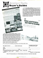
Buyer's Guides
11,
FOR AMATEUR
TH." SOURCEw
ROOK
A,QÇL
1
01 0
110.10
UIPMENT
j
O R141 T
N
$4.95
com.
a
(
You can buy with confidence when you have all the
facts. The 1991 Equipment Buyer's Guide gives you indepth coverage of H F /VHF /UHF rigs and accessories. All
the information is here in one handy, concise directory
with descriptions, technical specifications, model numbers, retail prices and photographs. How do you get a
ham license? What's the latest on the code -free license?
What equipment do you really need to work the satellites? Should you buy a computer for your shack? How do
you add computer control to your rig? You can buy with
confidence when you have all the facts. Order the 1991
Equipment Buyer's Guide today!
Art:r
1990 A
S4.95
NTENNa
sivyER,
Specs
Hundreds
Antennas,
Antenna Rotators,
s,
HF
VHF
GUIDE
and Acteur Radio
. Specifications
S
MoPbotos
bile
prices
Portable
You'll need the Antenna Buyer's Guide to squeeze
every last dB out of your antenna dollars. Make sure you
get the best possible antenna system for the best price!
HF and VHF, UHF, directional and omnidirectional, vertical and horizontal, mobile and portable -they are all covered in depth. Tuners, cables, wattmeters and more!
You'll find detailed charts, specification, photos and retail prices. Advice on getting the proper tower and antenna permits from a leading authority on PRB -1. Step -bystep guide to putting up your first beam! The bands are
hotter then ever right now. You can't afford to wait.
ORDER YOUR BUYER'S GUIDES TODAY!
Don't miss the most valuable buying guides in the Amateur Radio Field!
YES, please send me
EQUIPMENT BUYER'S GUIDE
ANTENNA BUYER'S GUIDE
copies at $4.95 each:
Name
Call
Address
City
State
Send only $4.95 each today. Foreign: $6 U.S. funds.
Check
MasterCard
VISA
Amex
Card No.
Signature
Zip
Money Order
Expires
(required on all charge orders)
Mail to: CO Communications, Inc., 76 North Broadway, Hicksville, NY 11801 /FAX: 516-681-2926
www.americanradiohistory.com
NIIII6ED/TOR/ALVIIN
arts
ExPpress
340 E. FIRST ST.
DAYTON, OHIO 45402
Modern Electronic Drafting
IDLER TIRE KIT
This popular
kit contains
170 of the
most popular
idler tires (10
each of 17
different
size
save
d money by having the right
tire in stock. Also included is a comprehensive cross reference listing over 80 manufacturers' assembly numbers and over 200
model numbers. (All tires are available
individually for reorder.)
$4995
#MM- 400 -900
VCR REPAIR PARTS KIT
With this
convenient
+
a art.A. vA - =s.
kit you can
do most of
your VCR
repair jobs
the same
day.
ed parts for RCA, Hitachi,
Co r%
Fisher, Sanyo, Lloyds, Panasonic, Sony,
Sharp, JVC, and more. Over 45 parts in all.
(All parts are available individually for
reorder.)
$8995
#MM- 400 -950
VCR SPRING ASSMT
A wide
assortment
of springs
used
many n
brand V
Clutch sings, idler springs, tension
springs, etc. 11 tension springs and 5
pressure springs.
$150
#MM-430 -300
VCR WASHER ASSMT
v
A wide
assortment
J
of plastic
washer
used in
clutch as
blies and idlers. 150 pieces,
split ring and regular.
#MM- 430 -305
rro P¡ss
f
$590
CALL
TOLL FREE
FREE CATALOG
1- 800 -338 -0531
Computer graphic systems have changed
the way many people draw electronic
schematic diagrams and create artwork
for making printed- circuit boards. Marrying mechanical drawing to computers
is nothing new-it began in the early
1960s. From a hardware viewpoint, it
started with mainframes, extending to
minicomputers and then to graphics
workstations. In recent years personal
computers have been used for this purpose, too.
The more powerful a PC is, the more
sophisticated accompanying software
can be. Even today's top -model PCs,
however, exhibit severe limitations in
what they can accomplish in the CAD
area. For certain applications, such as design work that requires solving analysis
problems, they're still too slow. For some
solid modeling uses, they don't have
enough memory for precise work.
Nevertheless, for many CAD purposes, they're very satisfactory. Furthermore, their relatively modest price makes
them exceptionally attractive since more
engineers can have access to the machines
for a host of CAD applications where
they work very well. In electronics,
they're especially effective for drafting
and for printed-circuit -board layouts.
Moreover, they serve well to train users
for work on much larger CAD/CAM
(computer -aided drafting /computer -aided
manufacturing) computers.
A particular boost for PCs in the electronics area has been the great increase in
symbol libraries. Consequently, a user
can quickly pluck a variety of electronic
device drawings from a library and place
them anywhere in a work area. It becomes easy to create interconnects, enter
text, edit drawings, etc. Sophisticated
software programs allow PCs to simulate
circuit operation, design chips, and even
do limited modeling and analysis.
With PC schematic programs now selling for under $100, wedding electronics
and computers is not even costly today
for anyone who wants to become CAD
trained, or draw schematics for personal
or educational reasons. Costlier pro-
grams open new vistas, which include
professionally created schematics and pcboard layouts. Moreover, one can add
symbol libraries for non -electronic drawing applications, such as landscape architecture, bathroom design, etc.
For high- quality work, you need good performance equipment, of course. You
won't get it with an old 4.7 -MHz computer with 255K user memory, a CGA video
monitor and a nine -pin dot -matrix printer. Also, you will definitely need a mouse
pointing device.
Some indications of how professionals
use CAD/CAM /CAE is revealed in a recent study by CAD /CAM Publishing
(841 Turquoise St., Suite D, San Diego,
CA 92109), which publishes a monthly
newsletter Computer Aided Design Report. It indicated that 47 percent of system owners plan to add work stations for
producing schematics, while 51 percent
plan such an expansion for PCB layout.
The most popular electronic engineering
applications for CAD are, according to
the study, drawing schematics (40 %), PC
boards (34 %), logic simulation (13 %),
analog simulation (10 %), IC layout
(10 %), timing analysis (10 %), and fault
simulation (8 %).
To get a better feel for what's available
in schematic drawing and printed- circuitboard layout programs in the personal
computer world, we examined a batch of
them from ones at low price points to
more costly packages. Additionally, we
worked with an educational software
package that simulates circuit activity
through output readings of softwaregenerated "instruments" of all kinds.
And we varied the type of computers and
peripheral equipment used.
The results of these efforts will be detailed here, starting next month. I think
you will find it to be both interesting and
inspirational since it's a field of endeavor
that weds electronics and computers, and
offers growing job opportunities.
CIRCLE NO.89 ON FREE INFORMATION CARD
8
/
MODERN ELECTRONICS
/
November 1990
www.americanradiohistory.com
Say You Saw It In
Modern Electronics
IIIiI/LETTERS/IIIIllM
Equivalency
Would you please supply me with equivalent numbers for
CMOS op amp IC1 and 3914 dot /bargraph display driver 1C2 for
the "Biofeedback Monitor & Lie Detector" featured in the August 1990 issue of Modern Electronics.
In the same issue appeared the "Darkroom Exposure Meter"
for which I would like to know the equivalent for the Vactec
V1200 photocell recommended for PC1. The text mentions that
this device is available from Allied Electronics and Newark Electronics. While this may be so, both sources have a minimum requirement of $25 per order, which puts building such projects beyond the reach of reasonable price.
May I suggest that if Modern Electronics wishes to sell magazines in Canada, full information about ICs and other devices
should be given so that equivalents can be purchased here without
having readers suffer the cost of postage, customs, etc.
John E. Sandon -Humphries
Logan Lake, B.C., Canada
The CMOS op amp you refer to is a specialized device that is
available in only 1,000piece quantities. The Note at the end of
the Parts List gives a source from which this chip can be obtained
in single -unit quantity. The 3914 is available from Digi -Key
(1- 800 -344 -4539), among other suppliers. The VT200 series was
cited as a typical example of the photocell to use. You can use any
other photocell that has the characteristics given in the article. -Ed.
744e 'Zee 66
VieN Sëee14púc2
1'1'11'1'11'1'1'1'\
SELECTION
\
Pp,t4AO
XcQllte
Sv+Bc
p0
ßCpIGE
Weller,
o f Modern Electronics?
0:2:3
\'''zw6
SAMS
rnorwEn,
Perspective, Please
RC/1
>?r
ri
What is the view of the Dinsmore magnetic sensor in Fig. 2 of
the "Digital Compass" project featured in the August 1990 issue
t
Ploneer, PYram
ed.
Swdchcjechnccalde,
11\111'11
Leviton.á un GC, pYle,
1
J.B. Craig
Marysville, CA
The view is from the bottom
re- stocked to virtually
eliminate backorders and
get your parts and components to you FAST!
NAME BRANS
vt
Py
8&K. Mueller and
sams
11 tintirands
SERVICE
Vo
Our friendly, knowledgeable
Sales Reps
are just a quick, TOLL
-FREE call away
to take your order or provide
tAOREt pected
M,
most res
at Mc
ndustry
WI the I
of the device. -Ed.
Cleaner Copy
The etching- and -drilling guide for the main pc board in Part 2
of the "Dual- Application Telephone Security System" that ap-
Our huge inventory of over
15,000 different items is
constantly monitored and
\
product
technical assistance when
you
need it. We also offer FAX
ordering, convenient hours
and multiple payment
options.
\
\
`,
FRFE CATALOG
CATp'EOG
il 1`#1
SPR, qp
''."' " p "
geared in the July 1990 issue of Modern Electronics appears to
have a few short c: rcuits between closely- spaced traces. Any
chance of getting a "clean" copy?
Catalogs,
543-4330
18
J.A. Furstman
Brooklyn, NY
The originalpc guide appears to have suffered from "ink bleed"
during printing. Here it is cleaned up but shown at 75% actual
size. You can easily clean up the original by working from this
copy. Alternatively, you can have this blown up to actual size for
direct use. Also note that the trace that originates at the pin 12 pad
for IC7 and passes between the pads for pins 11 and 12 for IC6
and terminates at the pin 21 pad of 1C2 should also be connected
to the pin -12 pad for IC6. -Ed.
Say You Saw It In Modern Electronics
SUBSCPIP
p
For FREE., MCM
E
TION to
TOLL-FREE,
MCM ELECTRONICS
650 CONGRESS PARK DR.
CENTERVILLE, OH 45459 -4072
A
PREMIER Company
SOURCE NO. ME -56
CIRCLE NO. 87 ON FREE INFORMATION CARD
November 1990
www.americanradiohistory.com
/
MODERN ELECTRONICS
/
9
Uil/il//NEW PRODUCTS III
-12 volts, both at 250 mA, and
For more information on products
described, please circle the appropriate number on the Free Information
Card bound into this issue or write to
the manufacturer.
volts at 500 mA. The device measures
7.6 " x 3.5 " x 1.3 ". $349.95; $34.95
power pack; $3 demo disk.
Universal Interface
Design Aid
Shelf-Size Stereo System
The micro -LAB computer peripheral
from Fisher Instruments (Bothell,
WA) is designed to be a universal
computer interface. It is intended to
be a design aid for use by engineers,
designers and students. Reported to
function with virtually any computer
that has an RS -232 serial port operating at 300 to 19,200 baud with no
handshaking required, micro -LAB
can be controlled via almost any
computer language.
Included in the micro -LAB package are a solderless breadboarding
socket, function generator, D/A and
A/D converters, fixed and program-
mable clocks, counter, audio amplifier and speaker, two eight -bit input
and two eight -bit output -only ports.
Sample applications and graphics are
also provided. All inputs and outputs
are TTL- compatible. Clock /counters include three crystal -controlled
clock sources, three 16 -bit timer/
counter control channels and one
eight -bit event counter.
Three eight -bit ± 10 -volt dc channels are provided, as are one eight -bit
10 -volt ac channel and one eight -bit
0 -to -10 -volt dc D/A converter. The
function generator provides sine,
square and triangular waveforms
with sweep input. A separately available power pack provides + 12 and
10
/
MODERN ELECTRONICS
/
CIRCLE NO.
51
+5
ON FREE INFORMATION CARD
Yamaha Electronics Corp. has a
compact stereo system that utilizes
Active Servo Technology to achieve
low and accurate bass response from
The speakers feature a 4Y -inch
midrange driver, 1 -inch tweeter and
Yamaha's YST air woofer. The cloth
speaker grilles are in an offset pear
shape to leave visible the open throats
of the air woofer ports.
Other system features include a
balance control and LEDs that show
volume level. Except for the rotary
Volume and slide -type equalizer and
balance controls, all functions are
operated via pushbuttons. An included 34- button infrared remote
controller duplicates virtually all
control functions on the console
unit. $999.
CIRCLE NO. 52 ON FREE INFORMATION CARD
High -Speed DSOs
small speakers. The Model YST -CI 1
consists of an Active Servo Technology amplifier, AM/FM- stereo tuner,
CD player, dual cassette decks, four band graphic equalizer and detachable stereo speakers. The amplifier
employs various types of matching
and feedback circuitry to produce extremely low and accurate bass response from speakers with a footprint of only 57/. by 91/2 inches.
The CD player at the top of the
console unit offers direct, random
and programmed access. It features a
20 -track calendar; track -selection
keypad; intro scan; auto replay synchronized to the cassette deck for recording; and built-in timer for wake up purposes.
An EQ record on /off cassette deck function permits adjustment of
the tonal qualities of the signal being
recorded and endless playback of
both sides of a tape. Dolby B noise reduction is provided for both decks.
Timer record /play permits the programming for later operation.
PLL synthesized tuning with direct
entry and 10 presets is featured in the
AM /FM- stereo tuner. A low-noise
AM loop antenna and a timer are
included.
November 1990
www.americanradiohistory.com
Hitachi now has two new lines of
high -speed digital storage oscilloscopes. Its 65 and 75 series DSOs
share such common features as:
100 -MHz analog /digital bandwidth;
two -channel simultaneous sampling;
2- mV /div. sensitivity; eight -bit vertical resolution; 4K record length;
100 -ns glitch capture, averaging and
roll modes; cursors, readout and save
memory; sweep time autoranging;
and built -in IEEE -488 GPIB inter-
face. All models also include
pre /post triggering, trigger lock,
digital processing and four-color
HPGL plotter output.
Acquisition modes provided include normal, average, envelope and
roll. Triggering can be set for peak to -peak, normal, TV -V, TV-H or
single. Frequency is measured automatically by all models, while P -P
(Continued on page 14)
Say You Saw It In Modern Electronics
How to build a high-paying career,
even a business of your own,
in computer programming.
baud internal modem, 640K RAM,
disk drive, monitor, and invaluable
programming software -BASIC, Pas cal, C, and COBOL-all yours to keep.
You get the experience and the
know -how, the computer and the
software to get to the heart of every
programming problem, design imaginative solutions, then use your choice
of four key computer languages to
build original, working programs.
No matter what your background,
NRI gives you everything you
need to succeed in programming,
today's top -growth
computer career field.
You need no previous experience to
build a successful programming career
RICK BRUSH,
NRI PROGRAMMER/ANALYST
Start with training that gives you
hands-on programming experience
-at home and at your own pace.
Training that begins with BASIC,
then continues with Pascal, C, and
COBOL -today's hottest computer
languages. Training that even
includes a powerful IBM -compatible
computer, modem, and programming software you keep.
Start with real -world training.
The kind of training only NRI
provides.
Now with NRI's new at -home training
in Computer Programming, you can be
one of today's highly paid, creative
team of computer wizards who give
computers the power to carry out an
astonishing range of business, professional, and personal applications. Now,
with NRI, you can be a computer
programmer, ready to build a high
paying career -even a business of
your own making computers do
anything you want them to do.
with NRI training. Indeed, your NRI
lessons start by walking you step by
step through the fundamentals, giving
you an expert understanding of the
programming design techniques used
every day by successful micro and
mainframe programmers. And then
the fun really begins.
You master today's
build programs for
debug, and
document
programs in
BASIC, Pascal,
training in Computer Programming,
send the coupon today. Soon you'll
receive NRI's fascinating, information
packed, full -color catalog.
-
Open it up and you'll find vivid
descriptions of every aspect of your
NRI training. You'll see the computer
system included in your course up
close in a special, poster -sized foldout
section. And, best of all, you'll find out
how your NRI training will make it
easy for you to build that high -paying
career -even a business of your own -in
computer programming.
Send
for your NRI catalog today.
It's yours, free.
If the coupon is missing, write to us at
the NRI School of Computer Programming, McGraw-Hill Continuing Educa-
tion Center, 4401 Connecticut Avenue,
NW, Washington, DC 20008.
IBM is a Registered Trademark
The only programming course
of the IBM Corporation
1
ArM, School of Computer Programming
that includes a powerful
computer system and
software you keep.
McGraw -Hill Continuing Education Center
4401 Connecticut Avenue, NW
Washington, DC 20008
Unlike any other school, NRI
gives you hands -on programming
experience with a powerful IBM
compatible West Coast computer system, including 2400
éi1ï
YES! Please rush me my FREE catalog describing NRI's
at -home training in Computer Programming.
NAME
Only NRI gives you an IBM -compatible computer with modem,
640K RAM, disk drive, monitor, and software-BASIC, Pascal, C,
yours to keep!
and COBOL
-all
For all the details about NRI's at -home
hottest computer languages, gaining the skills you need to
wide variety of real -world applications.
With your personal NRI instructor
-
Your career in computer
programming begins with
your FREE catalog from NRI.
a
on call and ready to help, you use your
computer and software to actually
design, code, run,
-
and COBOL. Then, rounding out
your training, you use your modem to
"talk" to your instructor, meet other
NRI students, even download programs through NRI's exclusive programmers network, PRONET.
C,
I
I
I
(please print)
AGE
ADDRESS
CITY /STATE /ZIP
www.americanradiohistory.com
Accredited by the National Home Study Council
5414 -110
J
NEW Pl
(from page 10)
voltage is also automatically measured by the 75 series only. Accessories provided with these DSOs include two probes (1 x /10 x switch able) and, for the 75 series only, a
64K IC memory card and an IC dummy card.
The Models VC -6075 ($4,195) and
VC -6065 ($3,995) feature 12.5 MHz
single -shot bandwidth and 50 MS /s
sample rate. The Models VC -6175
($4,695) and VC -6165 ($4,495) up the
ante to a 25 -MHz single -shot bandwidth and boost sample rate to 100
MS /s. Finally, the models VC -6275
($4,995) and VC -5265 ($4,750) boost
the sample rate to 200 MS /s. Available options include: an IEEE -488
interface card and GPIB cable,
DADisp V. 1.05B and V. 2.0 signal processing software for use in IBM
PCs and compatibles; IC card reader /writer; high -speed PC- transfer interface; color plotters; IC memory
card; etc.
CIRCLE NO.
53 ON
FREE INFORMATION CARD
Frequency Counter/ Timer
ZTEST Electronics Inc. (Mississaugua, ON, Canada) is now marketing
the Myoung Model RUC -1300 reciprocal universal frequency counter/
timer. The eight- decade instrument
Video Imaging Software
MFJ Enterprises' (Mississippi State,
MS) MFJ -1289 MultiCom IBM compatible software lets users of the
MFJ -1278 transmit and receive multiple gray -level weather fax maps,
SSTV pictures and AP news photos.
With it, you can also transmit and receive full-color packet pictures. The
package gives 80 One -Key Macros
and Call-Alert that sounds an alarm
when a preselected character sequence
is received by the MFJ -1278.
Auto -Set lets you instantly switch
modes without having to retype command parameters. Auto -Router lets
you store digipeater node routes for
instant digipeating. Packet MultiPlex lets you send and receive a packet message during a binary file transfer so that you can exchange programs without your QSO being completely cut off. Also included is Multi -Word, a word processor specifically designed for multi -mode communications. With it, you can bring up a
text file from within MultiCom and
transmit any portion directly from
that file. Multi -Word can also be used
for everyday word processing.
1
CIRCLE NO. 54 ON FREE INFORMATION CARD
14
/
MODERN ELECTRONICS
/
$59.95.
CIRCLE NO.55 ON FREE INFORMATION CARD
playing the result as a high -resolution
frequency. Basic sensitivity is rated
at 50 mV into megohm for the 100 MHz channels and 25 mV into 50
ohms for the 1.3 -GHz channel. Self test and the ability to hold a reading
are standard features. $485.
offers three input channels: two with
100 -MHz range and a third with a
I.3 -GHz range. The RUC -1300 measures frequency, period, period averaging, time -interval, ratio and sum/
difference of two channels and total izes. Reciprocal techniques are said
to accurately measure low frequencies by measuring the period and dis-
MultiCom lets you integrate an optional MFJ -1292 Picture Perfect Video Digitizer so you can shoot and
transmit a video picture via SSTV,
fax or packet.
With this program, you also get
menu control of your entire disk,
disk utilities for graphics screen capture and conversion to packet picture
format, disk of sample pictures, effective packet throughput readout,
screen colors set, sound on /off
switch, RS -232 cable and instructions. The program requires an IBM
PC XT /AT or compatible with 512K
of RAM and CGA, EGA or VGA
graphics and an MFJ -1278 multi gray level modem. The copy- protected program is distributed on three
" disks (3'/4" disks are available).
Updated Desktop Computer
Atari's new MC68000 -based 32 -bit
internal/ 16 -bit external 1040STE
desktop computer comes with a full
megabyte of memory for eight times
as many colors -4,096 in all -than
were possible with the predecessor
1040ST. It also features hardware-
November 1990
www.americanradiohistory.com
based smooth scrolling and a coprocessor BLiTTER chip for accelerated graphics speed. Upgraded
sound architecture in the computer
provides digitized pulse-code -modulation stereo sound.
Other features of this upgraded
computer include: internal 3.5 " floppy -disk drive; 8 -MHz operating
speed; built -in MIDI ports; built -in
TOS operating system with GEM
desktop; industry- standard modem
and printer ports; two analog joystick, DMA hard-disk and ROM
ports; and two- button mouse. A
software package included with the
computer provides spreadsheet, wordprocessing, educational and enter-
Say You Saw It In Modern Electronics
Multi-Pod EPROM Emulator
tainment programs that utilize the
computer's upgraded sound and
scrolling capabilities. The computer
measures 18 %" x W x 11/2 "D x
2% "H and weighs 9.5 lbs. $699.95.
CIRCLE NO. 56 ON FREE INFORMATION CARD
Scanner Antenna
Antenna Specialists' Model MON -53
all -band scanner antenna is available
for either roof or deck mounting.
The antenna utilizes an exclusive Micro-ChokeTM to achieve enhanced
performance in the 800 -MHz band
With Total Power International's
(Lowell, MA) Logimer 3 -Pod Emu latcr, you can emulate up to three
EPROMs simultaneously. EPROMs
tha= can be emulated include the
2764, 27128, 27256 and 27512. A second emulator can be interfaced with
the first to expand the total system to
six pods. With the 3 -Pod Emulator,
all you need do is connect the pods instead of the EPROMs and inject your
prcgram. Should modification be necessary, you simply press a switch to
modify your program. Having completed the emulation, you copy the
program into EPROM.
Using the Emulator, one can execute a split, join, update and checksum. The unit is compatible for binary, ASCII, Intel and Motorola systems. It is also possible to select addresses. Features include: multiple window software with mouse; command line or batch file execution;
split and merge of even /odd files;
calculation and file checksum; large
files split on three pods; pod contents
full page edition; data transfer
check; and copy of single file on
working file.
The Logimer 3 -Pod Emulator is
designed to run on IBM PC and compatible computers equipped with
384K of RAM. It features a power
switch, input to printer connector,
parallel input /output connector.
The hardware measures 10 %, " x 71/2"
x 1 % ". The accompanying program
supports both monochrome and color monitors. The system supports
512K devices and is fully windowed
with pull -down menus. The pods terminate in 28 -pin connectors that plug
into standard IC sockets. A 9 -volt
power supply is included. $1,499.
CIRCLE NO.59 ON FREE INFORMATION CARD
Deoxidizing Agent
without affecting performance at
other monitoring frequencies.
Included with the MON -53 is a 17foot coaxial cable with an installed pin
plug ready for immediate mounting
in a %" hole. All -band Micro -Choke
performance is also available with the
Antenna Specialists Model MON -52
mobile trunk -lid -mount and Model
MON -58 base -station antennas.
CIRCLE NO.57 ON FREE INFORMATION CARD
Say You Saw It In Modern Electronics
Caig Laboratories' (Escondido, CA)
Cramolin® DeOxidizer is said to be a
fast-acting solution that cleans, preserves, lubricates and improves conductivity of all metal surfaces, including gold. In use, DeOxidizer is
sprayed onto metal contacts, connectors and other metal surfaces to
quickly remove resistive oxides and
form a protective molecular layer
that adheres to the metal surfaces
and maintains maximum electrical
conductivity, reduces wear and protects the surface from future oxidation. It is for use on switches, potentiometers, relay contacts, plugs,
sockets, printed-circuit edge connec-
tors and more. The product comes in
an aerosol can and uses an ozone safe propellant.
CIRCLE NO.58 ON FREE INFORMATION CARD
November 1990
www.americanradiohistory.com
/
MODERN ELECTRONICS
/
15
NEW PRODUCTS
Speech Processing System
The MicroDyn II from Voice Dynamics Corp. (Irvine, CA) voice input /output system is reported to provide voice recognition of 1,000 words
of up to 1,000 characters per word
with an accuracy of better than 9807o
and unlimited text-to- speech synthesis. It listens to command or data input and then responds by sending
keystrokes via its serial port and text
to an on -board synthesizer for audio
prompting and verification. Creation, editing, voice training :esting
and maintenance are accomplished
from a standard MS /PC -DOS computer with supplied software. The
software includes sample vocabularies and allows the system to be used
with OS /2, UNIX, DEC, dumb terminals, emulators and custom OEM
applications.
The system features concurrent
operation of voice recognition, key-
board or barcode under the MS /PCDOS operating system. It transparently operates with standard application software. A word boundary indicator provides status of existing
noise levels and proper classification
of spoken words. The system is fully
compatible with IntroVoice VI vocabularies. It uses an 8086/8088 compatible NEC V -25 microprocessor operating at 8 MHz and comes
with 128K of battery-backed RAM
and 32K of on -board EPROM and
supports Lp to 128K of EPROM. It
operates asynchronously with an
IBM PC /AT/386 and PS /2 or compatible computer via a 25 -pin DB -25
connector/ cable arrangement operating at 9,600 baud.
Word groups can be isolated in
separate sub- vocabularies within the
same master vocabulary. By spoken
command, up to 15 independent subvocabularies can be accessed at any
time from a total of up to 100 sub -vocabularies. Miniature phone jacks
are provided for a microphone and
speaker. The system supports a wide
range of dynamic, electret and cardioid microphones (available as options). Power required is 5 volts dc at
185 milliamperes and is obtained
from the host computer over the serial cable. MicroDyn II measures 4 " x
3 " x l'/, " and weighs 1 lb.
CIRCLE NO.50 ON FREE INFORMATION CARD
Hyperflanger /Chorus Unit
PC Overcoat Pen
PAIA Electronics (Edmond, OK)
has reintroduced its Hyperflanger
and Chorus Unit analog sound -processing unit. An extremely quiet device, it is useful both in a studio and
for live processing. A hyper triangular control oscillator permits both
linear time sweeps and exponential
time sweeps that human ears prefer, both adjustable over a range of
71:1. An exclusive resonance lock
circuit allows a user to hang regeneration "on the edge" without having
to worry about breaking into feedback howls.
Designed to mount in a single
1.75 " standard rack space, the Hyperflanger and Chorus Unit requires
a power supply rated to deliver be-
Planned Products' (Santa Cruz, CA)
Circuit Works 3300 overcoat pen insulates, protects and repairs pc
boards, components and delicate
electronics. It is used in the same
manner as a writing pen. The 3300
applies a conformal coating that in-
tween ± 12 to ± 15 volts at 200 mA.
The kit includes pc board, all components, controls, hardware and assembly /users manual. $139.95; a
black anodized front panel with
printed control designations, $15.95.
CIRCLE NO.61 ON FREE INFORMATION CARD
CIRCLE NO.76 ON FREE INFORMATION CARD
www.americanradiohistory.com
sulates against short circuiting, arcing and static discharge as it protects
against moisture, abrasion, chemicals and other environmental hazards. When used to repair solder
masks, the pen is reported to improve
the reliability and safety of pc modifications and repairs.
The conformal polymer overcoat
material is available in several colors,
including green and clear. The mate nal is designed to match the durability and color of solder masking materials to assure nearly invisible repairs. It dries in 5 to 10 minutes at
room temperature and can be cured
at 50° to 100° C to enhance overall
performance. It is claimed to have
excellent adhesion to pc materials
and to be safe to use on gold, silver,
copper and solder alloys.
When not in use, the pen's springloaded tip closes to prevent drying
and clogging. The tip is self-cleaning,
and enough coating material is included to insulate and protect 60 feet
of exposed 1/6"-wide trace on a pc
board. $9.95
to prevent false triggering from ambient sunlight or a lighted fireplace.
The sensor and emitter are available
in standard, Decora and Decora Lens
styles, the last using a larger lens for
better off-axis transmission and
reception.
Agc circuitry increases the sensor's
sensitivity in proportion to the increase in distance between it and
hand -held remote transmitter. An ultra- bright LED, visible through the
sensor lens, gives visual indication
that the module is receiving data
from the remote transmitter.
The splitter and power supply can
be mounted in an out -of- the -way location. The splitter can accommodate up to four connections, and
splitters can be ganged so that up to
10 units can be operated from one
power supply and one sensor.
CIRCLE NO.63 ON FREE INFORMATION CARD
(Continued on page 81)
ELENCO & HITACHI PRODUCTS
AT DISCOUNT PRICES
rae
RSOs (Real -Time 8
NT.-- `
T
.F
From HITACHI
t hOscilloscloptes)
RSStoO
Compact Series Scopes
ly
View, Acquire, Test, Transfer and Document Your Waveform Data
100M53 (25MS/s on 4 channels slmuitaneously). 100MHz, 4kw x lob., 2kw
2ch
a
Delayed
1kw x 4ch. VC -6145
S
4,695,00
VC -6045
5
VC -6025
S
3,049.00
2,295.00
VC -6024
S
2,049.00
Compact, Full Feature Models
4OMSS, 100MHZ, 4kw
20MSs, SMMHZ, 2kw
x
5
"
Ich., 2kw x 261.
2111.
Model V-1065
- Shown
This series provides many new functions such as CRT
Readout, Cursor measurements (V- 1085/1065/665),
Frequency Ctr (V- 1085), Sweeptime Autoranging and
Trigger Lock using a 6 -inch CRT. You don't feel the
compactness in terms of performance and operation.
Low Cost /High Value Models
CIRCLE NO.62 ON FREE INFORMATION CARD
20MS
S.
50652, 2kw
a
2ch
20MSS, 20MHZ, :kW
x 2ch.
VC -6023
S 1,749.00
RSOsirom Hitachi feature such functions as roll mode, averaging, save memory, smoothing, interpolaton,pretriggering,
cursor measurements, plotter interface, and RS.232C interface. Weh thecomfon of analog and he power of digital.
Infrared Repeater
l
Sonance's (San Clemente, CA) new
ROAR (Remote Optical Amplified
Repeater) system provides remote
control of multiple -room audio systems or use in situations where a direct line of sight for infrared remote
control is not practical. It consists of
,;
e -.
at
a'
V -212
`
-`
DC to
V-660
V-665
V -1060
V -1065
V -1085
V -1100A
V -1150
Hitachi Portable Scopes
DC to S0MHz, 2- Channel, DC offset
$435
",
function, Alternate magnifier function
zoMtu
itl than., V-525 CRT Readout, Cursor Meas. $1,025
V -523 Delayedsweop
V-422 IGMHZ Dual Trace
522
$795
Brig
$995
Model
20MHz Elenco Oscilloscope
$375
5895
Dual Trace
-
I
1X,
>.
^.a
1mV Sensitivity
-
6KV
a
ll''
.....-.
NOW
CARRY
RM$4 1/2
Digit Multimeter
M -7000
!lr..4
al Operation
2 Axis
Delayed Trespass Swap
Includes 2 P l Probes
+
OF
$135
FLUKE
Models
83
21 F
85
87
8060A
73
8060A
75
80624
77F
eMOfB
CALL FOR
Provides sine, triangle square
wave from Dix 1p 1MHZ
_.-
..
earrgg
poled
^l
`...
ae
1000 Amps
47
Cas.
$18.95
Beata Sloa
ohm's IM .3
100K poi
Qdto
IOMFD
Digital Triple Power Supply XP -765
F
ly
f
.,
3
.
^OP OTO
SV
fie
5
.
a
-
- a.
-
0.
P
1
Ram
-- -- -- -
.
,2
1
without Freq. Meter $179
6
digit LCD
LEARN TO BUILD AND PROGRAM
COMPUTERS WITH THIS KM
Model
3A
MM-8000
$129,00
Swe
mw.
-
10MHZ
-- -
ar
rrr
wrath you wad a corm.* y.
Mao -Mawr
ywtwreelob RaMe.ROMs ant
BOe6m,aopocesw Tad** rtgvag. IBM PC. You .da wine able
era e.9moryiaa
rs
Pa^aput
m_
to 2MHi
w
g
memory in a
ports,
and IeamNrww bosw,t keyhowd
knowledge rewired. Simple easy w
to tun
ed. n ma
lammege
2
rM
ppr
yen E` PROM Teaches you
pu art
keyboard
el display No preunua ruin
blowhard loao-wn memos
you
ROBOTICS KR FOR ABOVE (MM -60107 $71.95
-
1245 Rosewood, Deerfield. IL 60015
(8001 292 -7711 17081 541 -0710
CIRCLE NO. 79 ON FREE INFORMATION CARD
www.americanradiohistory.com
31/2
INCLUDES : All Parts. Assembly and Lesson Manual
sewn, Triangle
Freq Co nter
UPS Shipping. 48 States 5 °a
($10 Max) IL Res., 7% Tax
1/ %basic act
protected
$249
GF -6015
DOMA
3Vtl.SA
with Freq. Counter
$V al SA
Memory eel
_
F
Function Generator
Sloe.
Will
uPee0 with Analog Meters $175
a
5
without meter 939.95
GF -8016
o-2491Á
0.20V tl IA
F: 3.
separate supplies
digital multimele
tl ZA
2Vtl1A
;u
M-5000
9wm$r45
Muse
Fes mrm1
$59.95
r
Autoranging DMM
$29.95
2.20V
,a
-9000
M -110CF
-
XP -580
-.egwal.aandennn
SG
RF Free 1001(-I50MMZ
AM NoduWim of lKHz
Variable RF output
.:
Temperature Probe
$275
" 1
$249
rpuW.r, Snit c rwn pdMed
21ime control,
_
'.N..'
wsmCapaeeNos
aw..aw
; ..
#9620
-2W
50.9500 w Digital Display and 150Mee bollr.ln Counter $249
Sweep
Cal&el
Hor
Reels Vohs &Freq
19610 or
I
,9610
Add
.
,
S -3000
Quad Power Supply
Decode Bloc
574010
4-
--.Rmae,
h
Tn.ppwWW
$69.95
o1
$1 -49
10Le4 DCorAC
Finest in the industry
10 rock steadypatlerns
AC Current Meter
e
u
t
GrouMed lÓ
DWBP.ak
-
!
2101ío et
zm -1sv al IA
,
Ras
4
raw
Wide Band Signal Generators
(w to 3oV el tAl
and 5Vel 3A
the den M features la doing experiments.
Features iron circuit (Navalen, el supplies.
0G -200
3Oooedode
with
$45
I
LC-1801
$125
2ero control
Cwtai. all
AM or FM capability
nold
Heal
"I-
Meter
'
Measures:
Coils 1uH -200H
Caps Iyf200u1
Assembled$65
it;,;1
4Ì4T
1
..
200uF
LCR
Lao
9Ranges
Apt-20.00(Mb
.5 %bus two/
1
Color Convergence Generator 10MHz Oscilloscope
Tempeyrlore Controlled
0
yI
Triple Power Supply XP -620
$28,95
Soldering Station
Termrap
Gollob/.. m
Blox
SPECIAL PRICING
infrared emitter, splitter, sensor and
remote power -supply modules. The
system utilizes standard four-conductor telephone cabling and connectors to reduce cost and simplify
installation.
The sensor and emitter mount in
standard light- switch junction boxes.
They utilize a specially formulated
Lexan lens that passes only IR signals
while rejecting all other wavelengths
-__ -
--
Digital
$58.95
'
Ac . DC Voltage a Amps
Resistance to 200?M0
Diode Logic, B Trans test
69600
.
'
Function Generator
23F
25F
73F
î
CM -365
$65
Accuracy
.1% Resistance
with Free. Counter
and deluxe use
MULTIMETERS
Function Digital Capacitance Meter
Multimeter
CM -1550
(
O5% DC
any accessories available for all
10
t.';
Acceleration Voltage
10.Rise Time
All scopes include probes, schematics, operators manual, and 3 y ar (2 yrs for Elenco scopes) world wide warranty on parts 8 labor.
Hitachi scopes. Call or write for complete specifications on these rd many other fine oscilloscopes.
WE
$495
MO-1252
-
..,
$1,195
$1,345
$1,425
$1,695
S2,045
$2,295
$2,775
Hipn luminance 6' CPT
kit
lox $19.95
P-2 100M1¢, lx, lox $23.95
P-1
x -Y Operation
TV Sync
2 p-1 Probes
.
r
SCOPE PROBES
Component Tesler
6'CflT
60MHz Dual Trace
60MHz Dual Trace w/Cursor
100MHz Dual Trace
100MHz Dual Trace w/Cursor
100MHz Quad Trace w /Cursor
100MHz Quad Trace w/Cursor
150MHz Quad Trace w /Cursor
Elenco 35MHz Dual Trace
Good to 50MHz
FREE DMM
with purchase of
ANY SCOPE
MO -1251
COMPLETE LINE
swap
LpMwalghl (1384)
2mV Sam
3 Yr Wananq
say ' oney 'ac
uaran ce
2 Year Warranty .,=- exb,ec M
WRITE FOR FREE CATALOG
17
Technology
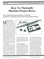
How To Thermally
Machine Project Boxes
Give a professional- looking finish to the plastic
enclosures in which electronic projects are popularly housed
By Adolph A. Mangieri
Machining the popular poly-
vinyl plastic project enclosures that have largely
replaced costlier phenolic project
boxes can be an exercise in frustration. Though shatterproof, these
boxes are made from a soft plastic
that has a relatively low melting
point. As a result, the bit of a hand
drill can tear or melt its way through
the plastic and "walk" excessively
from the exact point you want to drill
a hole. Grabbing action often turns
larger size holes into ragged and oval
shapes. Also, making the square and
rectangular holes required for mounting some components is done by tediously drilling many small holes and
filing the slippery plastic. You can
simplify machining of polyvinyl
project boxes with a few thermal
punching tools that you make yourself. In this article, we will describe
how to make these tools from readily
available materials.
The materials you need are brass
tubing from TV rabbit -ears antennas
for thermal punches and '/a -inch aluminum or brass shafts, couplers and
hubs. You can easily make and adapt
these tools to a small soldering iron,
which provides the heat source. Hole
sizes vary from under % to % inch in
diameter for use on thermoplastics
up to '%6 inch thick. Rounding out
the assortment of cutters, you can
make chisel knives and square and
18
/
MODERN ELECTRONICS
/
rectangular cutting tips. You will discover that, combined with conventional machining methods, thermal
machining can simplify installation
of components in thermoplastic project boxes.
Plastics & Machining
Common plastics fall into two general categories. Most of the plastics you
will encounter are members of a wide
variety of thermoplastic resins, such
as ABS, polyvinyl, acrylic and styrene. Thermoplastic resins are injection- molded under heat and pressure
to form the enclosures used for consumer electronic products, various
small electrical appliances and houseware items, to name a few.
November 1990
www.americanradiohistory.com
Thermoplastics may include fillers
such as waxes to add flexibility and
fibers to impart strength or better
machinability. When heated, this
type of plastic gradually softens at
first and eventually melts and finally
burns, with increasing temperature
emitting acrid and toxic fumes. Thermoplastics machine reasonably well,
provided you have a drill press and
operate it very slow using an assortment of brad- or spur -point bits.
Thermosetting plastics, such as the
phenolics, make up the second category of plastics. Thermosetting plastic is formed by chemical reaction between phenol and formaldehyde. it
does not soften when heated but does
eventually char at sufficiently high
temperatures. Thermosetting plas-
Say You Saw It In Modern Electronics
November, 1990
`1111
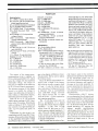
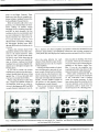
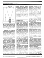
Fig. 1. Small hole cutters include thermal punches made from TV rabbit -ears
antenna sections and round, rectangular and knife shapes. Clean -out tool is
shown at bottom.
tics are used where high strength, di-
mensional stability and resistance to
high temperature are required. With
excellent electrical properties, the
plastic is widely used for switch
board panels, relay frames, motor
switch parts, and the plastic parts of
cooking utensils, toasters and steam
irons. Non -reinforced types are very
brittle. Products reinforced with fiberglass cloth or fibers are nearly unbreakable. Plastics including glass
and silica fillers quickly dull drill
bits. The relatively hard plastic is
easily drilled but may tend to chip
when the drill breaks through, and
large holes are usually a bit difficult
to machine.
Recommended for thermal punching is a 40- to 50 -watt soldering iron
that accepts '/4- inch -diameter slide in tips. A typical example of such an
iron is the Weller Model SP40 40 watt
unit shown in the lead photo. You
can easily make any needed adapters
and tools using 1/4 -inch brass or aluminum shafts, shaft collars, spacers
and hubs salvaged from TV tuners,
radios and the like. Multi -deck wafer
Say You Saw It In Modern Electronics
switches yield assorted spacers, and
metal inserts of knobs yield '/4 -inch
collars. The metal hubs of wheels and
gears of tuning mechanisms yield collars and'/4 -inch shaft couplers.
Shaft couplers, shaft extenders
and collars are usually available from
companies that cater to amateur radio needs. The thin -wall hard brass
tubing of TV rabbit -ears antennas
provides durable high- strength cutting tips. A single "ear" of such an
antenna usually consists of four sections of tubing measuring about '/,Z,
' %4, '/, 6 and % inch in diameter, all of
which can be put to good use as thermal hole punches.
Shown in Fig. 1 are four thermal
punches of assorted sizes installed on
adapters that have a '/4- inch-diameter upper portion. The adapters fit
into and are retained by a 1/4-inch
brass shaft extender, shown at top
left in Fig. 1. The shaft extender replaces the the original soldering tip
and butts firmly against the barrel of
the iron. It transfers axial punching
force to the barrel of the iron -not to
the inner end of the heating element.
You may need to cut the shaft of the
extender so that it does not bottom
out against the inner end of the heating element.
In lieu of a shaft extender, you can
make one by installing a 1 1/2-inch
length of brass shaft on a '/4 -inch
shaft coupler. Drill a small spot on
the shaft to firmly seat the setscrew.
Lacking a shaft coupler, make one
from a 3A4-inch -long by '/z- inch -diameter brass hub with a 1/4 -inch hole.
You may have to install one or two
6 -32 setscrews in a shaft hub salvaged
from a pulley or gear., Figure 1 also
shows a chisel knife tip at top- center,
a rectangular tip at top-right and a
clean -out tool at bottom.
When making the adapters shown
in Fig. 1, avoid high precision tight
fits because metal oxidation and
thermal expansion may create problems with "freezing" or binding. Be
aware, though, that a very loose fit
impairs heat transfer. Dimensions
specified are nominal and should be
altered as needed to match the sizes
of brass tubing you are using. Use
only brass or aluminum for the adapters, but feel free to modify the adapters to suit your own particular needs.
Adapters for %- and M6 -inch tips
shown at left in Fig. 1 are two -sided
collets. For the 'A-inch tip adapter,
use a 1- inch -long by ''h- inch -diameter
seamless spacer with 'A-inch through
hole. Grip the spacer vertically in a
vise. Then use a fine -toothed hacksaw to cut a 'A-inch-long slot lengthwise to form a two -sided 'A-inch collet. Slip a''/4 -inch shaft collar over the
slit portion, with setscrew positioned
90 degrees from the slot. Use the
' -inch
same size spacer to make a /,6
collet for the 3A6-inch tip. Using a /,6inch drill bit, enlarge the 'A-inch hole
in the spacer to a depth of 'h-inch.
Slot the drilled portion to form a
two -sided 3/,6 -inch collet. Then install
a '/4 -inch shaft collar on the collet.
Adapters for the larger '5/64- and
%2 -inch tips shown at the right in Fig.
1 utilize''/4 -inch solid shafts. Make the
November 1990
www.americanradiohistory.com
/
MODERN ELECTRONICS
/
19
adapter for the %4 -inch tip from a
1%-inch length of shaft. Chuck 9/6
inch of the shaft into a ''h -inch drill.
Slip a washer with '/, -inch hole on the
protruding end of the shaft to protect
the drill chuck. At low to medium
drill speed and using a flat file, reduce shaft diameter until the 1%4 -inch
tubing slides onto the shaft. Check
frequently as you file, using the tubing as a gage. When the diameter is
about right, use a finer file and finish
up with No. 240 sandpaper.
Install a ''h -inch shaft collar to grip
the tubing to this adapter. For the
9/2 -inch tip, cut off a 1'/ inch length
of % -inch shaft, which slides freely
into the 9/2 -inch tubing. Slightly enlarge the hole of a -inch shaft collar
to slide fit on the %2 -inch tubing.
Use a small tubing cutter to cut
rabbit ears tubing to length. Cut off a
2 -inch length of '%-inch tubing, and
square off both ends and remove
burrs. With a small tapered reamer,
turn the working end of the tip to a
knife edge. Then use a high -speed
hand grinder, such as a Mototool,
and a thin and abrasive cutoff wheel
to cut a %6- inch -long axial slot on one
side of the tip to form a clean -out
slot. Wear a face guard when working with the grinder!
Push the tip fully into the % -inch
collet with clean -out slot lined up
with the setscrew of the collet collar.
The setscrew tells you where to find
the clean-out slot. Cut off and prepare a 1%-inch length of/, -inch tubing and install in the M6 -inch collet.
Cut off and similarly prepare a 1 '/inch length of %, -inch tubing. Then
make a %- inch -long axial slot at the
upper end of the tip 180 -degrees removed from the clean -out slot. Install the tip on the adapter with set'
Fig. 2. Cookie cutters include large round and square hole makers made from
shells of battery cases and miniature r-f transformer shields.
'
6
'
screw aligned with the clean -out slot.
Prepare a 1 2 -inch length of 9/2 -inch
tubing and install on its adapter.
Figure 2 shows %- and 2 -inch
round "cookie cutters" and two
square cutters made from 2 -inch
lengths of deep -drawn thin -wall
20
/
MODERN ELECTRONICS
/
brass or stainless steel cups. For
round cutters, use the bottom portion of stainless -steel cases from
AAA and AA alkaline or nickel -cadmium cells. Use caution when cutting
these cells because the contents are
caustic. Thoroughly clean the cutters
and square up the open ends.
Bevel- sharpen round cutters inside
to a knife edge using a cone -shaped
mounted stone by hand. Drill a central hole in the bottom of the cutters
to pass a 6 -32 machine screw. For the
Weller Model SP40 iron, cut a 1'/inch -long by %- inch -diameter shaft.
For other irons, slide the shaft stock
fully inside the iron; then withdraw it
%-inch and mark and cut it to length.
Square up one end and drill and tap
axially for a 6 -32 machine screw. Secure the cutter to the shaft with a 6 -32
x -inch screw and lockwasher.
In use, the cookie cutters replace
the soldering iron tip, with cutter
butted against the barrel of the iron
to take up punching forces. These
cutters can also be retained by the
shaft extender to permit ready inter changability of all cutters. In this
case, and especially for the larger
cookie cutters, install slide -on spacer
bushings, as shown on the round cutters in Fig. 2. The bushings increase
heat flow and impart rigidity.
'
November 1990
www.americanradiohistory.com
You can use the brass or aluminum
outer fine tuning shaft of rotary-type
TV tuner switches to make the spacers. Make the spacers long enough to
butt firmly between the top surface
of the cutter and the front edge of the
shaft extender. Carefully square up
both ends of the spacer to assure
good thermal contact.
Use the brass shield of a subminature r -f transformer to make the %inch square cutter. Use the shield of a
miniature r -f transformer to make a
%-inch square cutter shown unmounted at the right in Fig. 2. Bevel
the inside edge of the tips to a knife
edge with a small fine flat file. Clean out slots are optional on these cutters
because you can easily pry out the
waste slug with a clean -out tool made
from the plastic handle of a toothbrush and a medium -size sewing needle. Drill a small hole in the end of the
handle and secure the the needle in
place epoxy cement.
The tip shown at the top -right in
Fig. 1 has a rectangular cutting edge
for roughing in the slots of slide
switches. To make square and rectangular tips, prepare and sharpen
the end of the tip but defer slotting of
the clean -out slot. Use the square and
rectangular tapered tangs of files as a
forming mandrel. If needed, true up
Say You Saw It In Modern Electronics
MATERIALS LIST
diameter brass or aluminum shafts
1/4 " brass shaft extender
1/4 "brass shaft coupler
1/4 " shaft collars (4)
1/4 " diameter spacers (1 " long with Y. "
hole)
TV rabbit-ears antenna (four sections)
AA and AAA alkaline or Ni -Cd cell
1/4
"
shells
Brass or aluminum spacer or hub (3/ "
long, 1/4 " hole)
Miniature and subminiature r-f transformer shield cases
Medium sewing needle
Plastic handle (see text)
Light -gauge sheet aluminum
40-watt soldering iron with 1/4 " tip
(Weller Model SP40 or equivalent)
Solid -state incandescent lamp dimmer
Ac line cord with plug
Small enclosure
Chassis-mount ac receptacle
5- ampere 3AG fast -blow fuse and
holder
the file tang on the grinding wheel.
Slide the tip firmly onto the tang
and pinch, peen and shape it until a
rectangle is formed. Because the hard
brass tubing is not highly malleable,
the rectangle may end up being slight-
II
ly barrelled. Lastly, cut a clean-out
slot in the tip as shown.
The beveled chisel knife cutter
shown at top- center in Fig. 1 handily
forms large cutouts. As an example
in making chisel knives, cut off a 1
inch length of ' %4-inch tubing. Pinch
one end flat for ''/ -inch in a vise to obtain a double- thickness flat blade.
One or both vertical edges of the
flattened portion will probably split.
Select the best side of the flat blade
for the knife, and remove the other
side, leaving a single thickness blade.
Do this by scoring the blade M6 inch
from the end with a fine triangular
file and pry off the waste portion.
Use a file to true up the blade and
bevel it on one side to a knife edge.
Assorted tool guides or templates
and a panel machined with these
tools is shown in Fig. 3. Use light gauge aluminum sheet to make templates. Lay out and drill the holes
slightly undersize and ream to final
size to clear the tip. Scribe cross -hair
lines. Make the DB9 connector template shown at top -left in Fig. 3 by
drilling a number of small holes and
filing the hole to final size. Metal
frames of miniature and standard
I
Fig. 3. Hole templates and switch bodies aid machining of panels.
Say You Saw It In Modern Electronics
slide switches and other components
serve well as tooling templates.
You need a means to adjust the
voltage applied to the soldering iron
used with your home-fabricated
tools. I use a bench powerstat (variable- voltage transformer) with calibrated dial. It has two ac receptacles,
which permit operation of two hot punch irons at the same time. You
can use a full -range solid -state traic
motor speed controller instead. An
inexpensive wall -mount solid -state
rotary incandescent light dimmer
that handles loads up to 600 watts
performs just as well.
Wire together the dimmer and iron
as shown in Fig. 4. Install the dimmer
in a small enclosure and calibrate its
dial in 10 -volt steps from 60 volts to
maximum. To calibrate, connect a
60-watt incandescent lamp and an ac
voltmeter (preferably true -rms -not
peak -type) to the "load" side of the
dimmer.
Using the Tools
Like in soldering, the technique used
to machine thermoplastics with thermal tools requires some practice at
first to master it. For hot punching
with little or no melting of the plastic,
the rate of heat flow and tip temperature is just sufficient to allow the tip
to be forced through the plastic with
moderate downward pressure on the
tool. The tip softens the plastic and
you push the tip through the plastic.
At appreciably higher temperature, the plastic melts rapidly and
very little force, if any, is needed as
the tip penetrates the plastic. However, high heat often produces acrid
toxic fumes and fouling of the tip
with sticky plastic. Therefore, the
objective is to use the tools at lower
temperature to avoid fumes and
fouled tips.
Practice on scrap pieces of vinyl
siding, ABS plastic taken from TV
cabinets and plastic housewares until
you perfect your technique. Initially,
operate the soldering iron at 117
November 1990
www.americanradiohistory.com
/
MODERN ELECTRONICS
/
21
volts. Then, after a 3 -to -8- minute
warm -up period, position the iron
vertically and push down on the plastic while moving the top of the iron in
a small circle. Place a piece of tablet
back or chipboard under the plastic.
At 117 volts, the tip is likely to be
too hot, penetration will be rapid and
some sticking of plastic to the tip will
occur. If so, lift the iron after penetration and quickly remove the waste
slug. Wipe the tip with fine steel wool
or a heavy cloth to remove the adhering plastic. If the plastic melts inside
the the tip, twirl a small drill bit Inside
the hot tip to remove it.
Perform trials with the powerstat
or light dimmer set to 40, 60, 80, and
100 volts in turn. At insufficient input power, heat flow down the thin
walls of the tip will fail to soften the
plastic. At about 80 to 100 volts, the
tip will heat sufficiently to soften the
plastic and permit you to push the tip
through in 2 to 4 seconds without creating fumes, melting the plastic or
fouling of the tip. The holes will have
little or no burrs, and the waste slug
will be barely deformed, if at all. This
is the desired operating condition.
Usually, the powerstat is set for 70 to
100 volts after initial warmup at 117
volts. If you are using a solid -state
controller with arbitrary dial calibration, take note of the dial indications
as you determine the correct setting.
Figure 3 illustrates a plastic panel
machined with the thermal punches.
At left from top to bottom, the cutouts accept a phono jack, miniature
slide switch, standard slide switch
and DB9 connector. At lower -right,
the large cutout accepts a Centronics
parallel printer connector. The series
of graduated holes at top-right accept screws and a wide variety of
jacks, switches and potentiometers.
(Use a reamer to increase hole size as
required.) Below are several holes
punched with the squared cutters.
To make the hole pattern for slide
switches, position the template at the
desired location with clear double-
22
/
MODERN ELECTRONICS
/
sided tape. Use a square or oblong shaped cutter to remove the waste
material in the oblong hole in several
penetrations. Punch the mounting
holes and remove the template.
Touch up the oblong hole with a
small file. If necessary, slightly ream
the two mounting holes.
When making cutouts for DB -style
connectors, proceed in a similar
manner. When using the beveled
knife for DB- connector cutouts,
place the flat surface of the cutter
against the edge of the template and
make a series of overlapping penetrations. If necessary, use an X -acto or
other hobby knife to break out the
large waste slug. Finish the edges of
the hole with a small file. For large
oblong cutouts, lay out the hole pattern in pencil. Place a thin metal strip
along the edge of the pattern and use
it a a guide as you cut the hole with
the chisel knife.
With close observation and slight
twist of the tool, you can usually feel
and determine full penetration of the
tip through the plastic. Tip penetration is easily felt by allowing the tip to
fall through the plastic by about '/,6inch . Place a'/, 6 -inch thick chipboard
shim under the workpiece but clear
of the hole. Alternatively, use a sheet
of dense foam plastic as a backup to
readily feel and limit penetration of
tip through the plastic.
Holes for miniature and subminiature phone jacks are preferably hot punched with the aid of the centering
template. The hole can be punched
slightly undersize and enlarged with a
tapered reamer. A piece of wood held
in a vise provides backup on the inner
walls of a project box.
When making medium to large
round holes, the waste slug can be
made to remain in the plastic, eliminating the need to remove the waste
from the tip. Push the tip through the
plastic without axial rotation. The
plastic in the clean -out slot retains
the waste in the panel. Use a pencil to
push out the slug. To lift the waste
November 1990
www.americanradiohistory.com
600W
rotary lamp
dimmer
5A
slow-blow
fuse
Chassis -mount
ac receptacle
117Vac
Fig. 4. Wiring details for light dimmer
and soldering iron circuit.
with the tip, rotate the tool slightly
after it penetrates the plastic to cut
the material in the clean -out slot.
When machining the panel of a
plastic project box, cover the entire
outer surface of the box with masking tape to avoid scratches as you
work. Mark hole locations on the
tape and punch from the outer surface. At correct tip temperature (not
critical), the holes produced are remarkably clean. At higher heat and
with thicker panels, a small annular
ring may form on the entrance and a
small burr on the exit sides of the
hole. Remove burrs using the countersink bit or knife.
These thermal punches are intended to be used on plastics up to 3/6 inch
thick. Holes were punched in plastics
up to '/, inch thick, but such a thickness requires more heat and time to
penetrate the plastic. Filled plastics,
such as ABS TV cabinets, punched
satisfactorily. Acrylic and styrene
plastics tended to foul tips.
After several hours of use, remove
the shaft extender from the iron and
clean both to prevent buildup of oxides and seizing. From time to time,
remove the shaft collars from the
tips, and the tips from the adapters
and clean them with fine steel wool.
Variations
The following may prove to be
helpful if you experiment with larger or smaller -wattage soldering irons or
cutter tips that are different sizes and
Say You Saw It In
Modern Electronics
RACK CHASSIS
FOR THE
CONSTRUCTOR
ALL
CONSTRUCTED
ALUMINUM PARTS. THE
RU
=1.75'
lengths. For a given power input to
the soldering iron, the heat available
to soften the plastic is primarily limited by the effective thermal conductivity of the relatively thin walls of
the cutters. Halving tip length doubles the heat flow. Stainless -steel cutters are relatively short because this
material is a poor conductor of heat.
The tips shown in Fig. 1 can be
adapted to a soldering iron that accommodates Y8-inch screw -in tips.
After you identify the threads on the
original soldering tip (probably metric), you will need a screw tap that
matches the threads of the soldering
tip and corresponding machine
screws. Drill and tap the upper end of
the collets or adapters to accept the
machine screw. Install the screw in
the collet, driving it in until it binds
firmly. Cut of excess screw length.
Tips so constructed tend to work
loose but otherwise perform well.
Limit tip size to smaller diameters.
Thermal shaping and cutting tools
are frequently used in plastic arts and
crafts projects. You may have need
for larger cutters and chisel knives
best adapted to higher- wattage soldering irons. Relatively compact,
Weller's Models WP80 80 -watt iron
with % -inch slide-in tip and WP100
100 -watt iron with Y2-inch slide -in tip
are recommended for heavy-duty use
in punching larger holes. Cutters
made from C- and D -size cells were
adapted to the larger iron and performed well.
S
1 RU5
1.75 x 19 x 5
1.î5X 19 X 7
1 R07
1.75 x 19 x 10
1 RU10
2RU5 350 x 19 x 5
2RU7 350 x 19 x 7
2RU10 3.50 x 19 X 10
3RU5 5.25 x 19 x 5
3RU7
5.25
x
19x7
3RÚ105.25 19x
10
PRICE
28.00
30.00
32.00
30.00
32.00
34.00
38.00
40.00
42.00
SESCOM, INC.
CUM
BRUSHED
NODIZED
SHIPPED FLAT 1UNASSEMBLEDIBLACK
MODEL SIZE (H,W,O')
lS
OTHER FAMOUS MANUFACTURERS
FINEST WARRANTY PROGRAM AVAILABLE
LOWEST RETAIL/WHOLESALE PRICES IN U S
ORDERS SHIPPED FROM STOCK WITHIN 24 HOURS
FOR FREE CATALOG ONLY 1. 800-345 -8927
FOR ALL INFORMATION 1- 818 -709 -9937
SEMIPROFESSIONAL
PRODUCTS,
VISA ACCEPTED
ORDER DIRECT FROM
PREPAID ORDER.
SHIPPED DIM OROUND nun
PACIFIC CABLE CO. INC.
NEET
YAIR SWAN
2100 WARD DR.
HENDERSON, NV. 89015 U.S.A.
FAX (702)565-4828
E73251/2 RESEDA BLVD., DEPT. 1204
RESEDA, CA 91335
I1 i
vGE!
h*trical
e ,i,/ Books
BOOKS!
TESLA
Discover the finest collection of quality
INCREDIBLE
BOOKS!
If you haven't received
your copy of Lindsay's
Electrical Books catalog, you've
really missed something! You'll
find one of the most bizarre collections of paperbacks, pamphlets, industrial references on
incredible plans, lost
Tesla books available, including both new
books and reprints of very old. rare publications. Discover a new booklet on Teslá s
lost inventions, a 1904 book on Teslá s
experiments with wireless power trans mission, rare and unusual books on the
construction and use of high voltage
Tesla coils, and much more! Highest
quality guaranteed!
.1
.-
18
Build Lightning
Bolt Generators!
secrets,
forgotten
events, and strange
theories ever
assembled!
Build a Wimshurst
machine, Telsa Coil,
Oudin Coil, Induction Coil, Winter
static electric machine! More! Build
Jacob's Ladder, con-
CATALOG
PACKED
WITH
UNUSUAL
densing
PLANS!
neon signs. rewind motors, get high
power from auto alternators and generators, build a spot welder, an electric
scooter. an arc furnace to melt metal,
build a storage battery, a high performance crystal set, even a dangerous X -Ray
machine! It's all here. Write for your copy
Build
solar cell! Turn sunlight
into electricity! Perhaps not the highest efficiency, but low cost!
Really works! It's for
real. Complete plans!
Write for
CATALOG!
Write for your copy of Lindsay's
new Electrical Books catalog and
see for yourself what you've been miss-
$1.00 (US & Canada) or
$4.00 foreign airmail. We'll send your
catalog immediately! Write today!
ing! Send
electro-
scopes, Leyden jars,
scintillating tubes, electrical cannons, Cavallo's cylinder machine and much
more! Great science projects! Most complete collec-
Write for a catalog! Learn how to make
SOLAR CELLS!
... what's a pencil ?"
# # # ##
STARRING
PUNCHES
PRESS-ON LETTERING,
HAND PUNCH TOOL
ANO PUNCH KITS,
AND OUR UNE OF OVER
300 PROFESSIONAL AND
Build a genuine working
school tomorrow
# # # ##
CIRCLE NO.91 ON FREE INFORMATION CARD
today!
The teacher wants us to bring a pencil to
.1r
JERROLD, HAMLIN, OAK
AND
SENDFOR FREE CATALOG
OF SHEET METAL BOXES,
RACK CHASSIS, RACK
METAL
# # # # # PRESENTING
CABLE TV
DESCRAMBLERS
NELS
FRONT 6 REAR PANELS
ARE CLEAR BRUSHED
ANODIZED. THE BALANCE
OF THE PARTS ARE
tion of high voltage
books you'll find anywhere!
RARE EARLY
RADIO BOOKS!
Incredible collection of
early shortwave radio
books, disc television,
unusual radio experiments, and more! You'll
even discover a strange collection of books on
lost continents, perpetual
"Fringe Science
motion, unusual phenomena recorded throughout the centuries, and much more. Explore the
strange world that lies between fact and fiction!
-
rLindsay's Electrical Books,
Box 583 -WE6, Manteno IL 60950
L..1
Enclosed Is $1.00. Send me a copy of Lindsay's
Electrical Books catalog via first class mail?
I
I
I Name
I
IAddress
Lity
St
Zip
J
23
amENNENERNEREM...
www.americanradiohistory.com
Project
An Infrared
Thermometer Accessory
Lets any DMM measure temperatures fast- without
requiring physical contact!
Thomas R. Fox
thermometer can
do seemingly amazing things
-measure the temperature
of a cloud layer from the ground and,
with a special rig, the surface temperature of the moon and Mars. More
mundane uses include temperature
measurement of moving objects and
non-contact measurements of hazardous objects like high -voltage and
radioactive equipment. The response
of an IR thermometer is also fast!
An infrared thermometer is also
useful in applications in which contact thermometers are traditionally
used. For example, it can be used for
making quick checks of building insulation and weather- stripping for
estimating heating /cooling loss.
Too, a non -contact infrared thermometer that accurately measures
temperature in the 85° to 115 °F range
has obvious utility in medicine. Good
as it is, though, the infrared thermometer cannot fully replace the
mercury thermometer, whose advantages include greater accuracy and
lower cost. But for specialized non contact measurements, the infrared
thermometer cannot be beat.
The IRTA Thermometer accessory plugs into the inputs of a handheld DVM or DMM set to dc volts; so
no enclosure is required. Except for
the probe assembly, all components,
including switches and battery,
mount on a printed- circuit board.
An infrared
24
About the Circuit
The complete schematic diagram of
the IRTA Accessory is shown in Fig.
1. The output of thermopile detector
IRSI is connected to the noninverting ( +) input of ICI. With a 1,000ohm value for R1 and 150,000 -ohm
value for R2, IC1 amplifies the output of IRSI by 151 (1 + 150). This
amplified output is connected to R3,
which forms one leg of the summing
amplifier. The other input to this
summing amplifier comes from 1C2,
which provides the temperature compensation voltage for the circuit.
Actual design of the temperature compensation circuit is a bit involved
mathematically and will not be presented here. The goal here is to have
the thermopile detector respond only
to temperature differences. There-
/ MODERN ELECTRONICS / November 1990
www.americanradiohistory.com
fore, either the reference junction
must be maintained at a constant
temperature or the reference junction temperature must be measured
and used to compensate the circuit.
This instrument uses automatic temperature compensation.
Temperature measurement of the
reference junction of the sensor is accomplished with LM335 temperature
transducer IC/O. This transducer attaches with a thermally- conductive
cernent to the TO -5 header leads of
IRSI. According to Dexter Application Brief -2, the leads of the detector
is the best place to monitor the temperature of the reference junction.
The value of R10 is chosen to be as
large as practical to minimize selfheating of ICS. The temperature compensating circuit is made up of
1C2, R6, R8, R9 and 105.
Say You Saw It In Modern Electronics
o
>n
Z
0
+
O
O
O
IA
z
O
J
LL
U
o
ó
N
o
U
Lc)
o
o
1k'
co
w
>
Lo
v
/
U
o
U.-o
Y
o
LO
o
W
J
U
'
JV\ró
-1/NA,
in Y
ó
i
rn
Z
CC
N tL
U
p
LO
CC
co
c
*) rn
C_
Y
uo
p
V
CC
(.6
Y
O
LL
-
Z_
()
U ó
ó
ct
)4)
Ú
I
cv
¢ ó
d
o
o
Ú
o
Z
Say You Saw It In Modern Electronics
f
'
'
u_
x
UU
1
o
in °)
-
CC
ai
L----J
Fig. 1. Complete schematic diagram of Infrared
Thermometer Accessory.
November 1990
www.americanradiohistory.com
/
MODERN ELECTRONICS
/
25
PARTS LIST
Semiconductors
D1 -1N914 or similar silicon diode
ICI thru IC4 -OP -177 precision operational amplifier (see text)
IC5-LM335Z temperature transducer
IC6- LMC7660 voltage converter
IC7- LM2931 fixed + 5 -volt regulator
IC8 -79L05 low -power fixed 5 -volt
regulator
IC9- LM336 -2.5 2.5 -volt precision
voltage reference
LED1- Low -power, high- efficiency
red light- emitting diode
LED2- Low -power, high -efficiency
green or yellow light -emitting diode
Capacitors
Cl thru C8,C14-0.1 -µF, 50 -volt ceramic monolithic
C9,C10,C12,C13- 10 -µF, 25 -volt electrolytic
C 11- 220-µF, 25 -volt electrolytic
Resistors ('/ -watt, 1% tolerance)
R1 -1,000 ohms
R2- 150,000 ohms
R3 -6,980 ohms
R5- 46,400 ohms
R6,R7,R9- 10,000 ohms
R8-11,300 ohms
The output of the temperaturecompensating circuit is applied via
R5 to summing amplifier IC3, which
sums this voltage with the amplified
thermopile voltage. The output of
IC3 goes to a degree circuit made up
of S2, IC4 and related components.
The primary purpose of this degree
circuit is to modify the voltage to
make it (in millivolts) correspond to
either Celsius or Fahrenheit degrees,
depending upon the setting of S2.
With S2 set to °F, 50 millivolts
yields a meter reading of 50 °F. Similarly, in the °C position, 50 millivolts
yields a reading of 50 °C. Switch S2
also controls two light-emitting diodes: red °F LED2 and green °C
LEDI.
Calibration for this circuit
is ac-
complished with R16 and R4. Potentiometer R4 is used to adjust the gain
of the amplified thermopile voltage
and R16 provides a small offset volt-
26
/
MODERN ELECTRONICS
/
R10,R19 -2,740 ohms
R11- 118,000 ohms
R12- 215,000 ohms
R13,R15- 100,000 ohms
R14- 84,500 ohms
R17- 20,000 ohms
R18 -1,000 ohms (5% tolerance,
'/ -watt)
R4- 10,000 -ohm, 15 -turn pc -mount
trimmer potentiometer
R16 -1,000 -ohm, 15 -turn pc -mount
trimmer potentiometer
R20-50 -ohm, pc -mount trimmer potentiometer
Miscellaneous
BI -9 -volt alkaline battery
P1,P2- Banana plug
IRS1 -1M thermopile detector with argon gas and 6.5 -to -15.5- micron LWP
filter (specify argon gas and LWP filter; $50 + $2 P&H from Dexter Research Center, Inc., 7300 Huron River Dr., Dexter, MI 48103; 313 -4263291)
S1 -Spst pc -mount slide switch (DigiKey Cat. No. SW 100-ND)
S2 -3pdt
miniature pc -mount slide
age to the degree calibration circuit.
Potentiometer R20 is used to adjust
the Celsius circuit.
Since the IRTA Thermometer accessory uses a single 9 -volt battery
(B1) and the circuitry requires both
+ 5 and 5 volts for proper operation, some type of voltage conversion
is required. This is accomplished
with LMC7660 voltage converter
IC6, which converts the + 9 volts
from B1 to the 9 volts required by
the summing amplifiers.
The 9 volts that exits at pin 5 of
IC6 is unregulated. It is passed
through IC8, which outputs a tightly
regulated
5 volts. The + 9 -volt
source from B1 also goes to IC7,
which outputs a tightly regulated + 5
volts. Thus, all voltage requirements
of the circuitry are satisfied by the
relatively simple IC6/IC7/IC8 power supply arrangement.
Bear in mind that the values of sev-
November 1990
www.americanradiohistory.com
switch (IDigi-Key Cat. No. SW 121 -ND)
Main printed-circuit board or perforated board with holes on 0.1 " centers
and suitable Wire Wrap or soldering
hardware and enclosure (see text);
detector pc board; sockets for all DIP
ICs; 3- contact plug /socket pair (DigiKey Cat. No. A1493/A1436; optional
-see text); 9 -volt battery snap connector and holder; three -conductor
cable with red-, green- and black -insulated conductors; 11/2 "L x '/ "ID
yellow CPVC pipe; 1% "L x 11/2 "ID
white PVC pipe; 5 "L x 1'h "ID white
PVC pipe; epoxy cement; cable tie;
insulation; duct tape; aluminum
paint; solder; etc.
Note: The following items are available from
Magicland, 4380 S. Gordon, Fremont, MI
49412: Complete kit of parts, including all
ICs, main and probe pc boards and all other components (pipes, cables, etc.) but not
including IRS1, battery and optional
items, Kt. No. IRTA -MAG1, $49.50;
OP -177 op amps, each $2.50.
Digi -Key is located at 701 Brooks Ave. S.,
P.O. Box 677, Thief River Falls, MN
56701 -0677; tel. 1-800-344-4539.
eral resistors used in this accessory
depend on the geometry and material
of the thermopile probe. For instance, the value of R2 depends upon
the internal diameter and length of
the pipe in the probe assembly. So
keep in mind that the values given in
Fig. 1 and specified in the Parts List
were selected for the prototype probe
described later.
Ultra- precision OP -177 devices
are recommended for all operational
(summing) amplifiers. Specifications
of the new OP -177 are significantly
better than those for the famed OP07-at about the same price. For optimum operation, ICI requires the
tightest possible specifications,
which means that an OP -177 or its
equal should be used here. For IC2,
IC3 and 1C4, the specifications are
not as critical; so you can use less -expensive op amps -even a 741
economize.
-to
Say You Saw It In Modern Electronics
NOTE.
*P1 and P2 mount on trace side of board.
Fig. 2. Actual-size etching- and-drilling guide
printed- circuit board.
Construction
If you prefer not to fabricate a pc
board, you can assemble the circuitry
on perforated board that has holes
on 0.1 -inch centers, using suitable
Wire Wrap or soldering hardware. If
you go this route, make the connections to the meter via short cables terminated in banana plugs and house
the assembly in a small enclosure.)
Fabricate the pc board using the actual -size etching-and -drilling guide
shown in Fig. 2. If you do use this
guide, be sure to use the recommended battery holder and switches. Begin
populating the board by installing
and soldering into place sockets in all
DIP IC locations. Do not plug the
ICs into their respective sockets until
after you have conducted initial voltage checks and are satisfied that the
circuit is properly wired. Next, mount
the banana plugs in their respective
Say You Saw It In
Modern Electronics
for main
Fig. 3. Wiring guide for main pc board.
locations on the copper-trace side of
the board. After they are physically
mounted, spot solder the banana
plugs to the copper pads surrounding
them to assure good electrical connections.
Now install and solder into place
the resistors, trimmer controls, capacitors, diode and LEDs in their respective locations. Make sure the
electrolytic capacitors, diode and
LEDs are properly oriented before
soldering their leads into place.
Continue populating the board by
installing and soldering into place
1C7, 1C8 and 1C9, making sure you
follow the basing diagrams given in
Fig. 1. Trim the leads of a 9 -volt battery snap connector to a convenient
length and strip 'A inch of insulation
from each. Tightly twist together the
exposed fine wires and sparingly tin
them with solder. Plug the black -insulated lead into the hole labeled BI -
and solder it into place. Similarly,
plug the red -insulated lead into the
hole labeled BI + and solder it into
place. Mount a 9 -volt battery clip
holder in the space reserved for it at
the top of the circuit -board assembly
with 4 -40 machine hardware. Finally, mount the switches in their respective locations. If you wish, you can
mount a cable connector in the area
just above RIO (see Parts List).
Carefully examine the circuit board assembly to make certain that
all components are installed in the
proper locations and that those that
require polarization and special basing are properly installed. Turn over
the circuit -board assembly and carefully check your soldering. Solder
any connections you may have missed,
reflow the solder on any suspicious
connections and remove solder
bridges, especially around the closely
spaced IC socket pads, with a va-
November 1990
www.americanradiohistory.com
/
MODERN ELECTRONICS / 27
Cement ( -) lead of
IC5 to case lead of
105 (cement to case of IRS1)
IRS1
Output pin ( +)
Output pin
(
-)
Output pin ( +)
IRS1
Cement IC5 ( +) lead to
IRS1 case
Fig. 4. Epoxy cement top of LM335 (IC5) to bottom of thermopile detector
(IRS 1) case and connect together leads as illustrated.
cuum -type desoldering tool or desoldering braid. Then temporarily set
aside the circuit -board assembly.
Though the design of the basic circuitry is fairly straightforward, if
you use an ultra -precision op amp
like the OP -177 for /C/, probe design
is simple but not trivial. As shown in
Fig. 4, begin fabrication of the probe
by cementing, with fast - setting epoxy
cement, the top of the case of IC5 to
the bottom of the case of IRSI. Position the two devices as shown.
When the cement has fully set,
loosely twist together the positive
( +) lead of IC5 and the case lead of
IRSI and solder the connection. This
assures that IC5 measures the reference- junction temperature of IRSI.
You should use a printed- circuit
board on which to mount the IRS1/
IC5 combination and wire to it the
cable that connects the probe assembly to the main circuit. Fabricate this
board with the aid of the actual -size
etching-and -drilling guide shown in
Fig. 5(A). Once the board is ready,
mount the IRSI /IC5 assembly on it,
as shown in Fig. 5(B).
Now remove 1 inch of outer plastic
jacket from both ends of a 24- to 36inch length of three conductor cable,
preferably with insulation color coded red, green and black. Twist together the exposed fine wires in all
conductors at both ends of the cable
and sparingly tin with solder. Plug
the conductors at one end into the
holes specified in Fig. 5(B) and solder
them into place. Note that the cable
conductors plug into the coppertrace side of the board.
The internal structure of the probe
assembly consists of a 1'h -inch
length of a 1/2-inch inner -diameter
CPVC plastic pipe and the small pc
board used to mount the detector/
transducer assembly, as shown in
Fig. 6. Common CPVC plastic water
pipe is a good choice for the housing
of the probe assembly. The ideal
material is a tube that absorbs infrared energy in the 6.5 -to- 15.5- micron
wavelength region but does not emit
infrared in this wavelength band.
CPVC may have at least a slight tendency to this ideal characteristic.
The excellent directional characteristics of the probe assembly indicates that CPVC absorbs most infrared energy in the 6.5 -to -15.5- micron
region. The main circuit compensates somewhat for the potential error caused by the IR emissions from
the tube striking the thermopile detector. The primary error here arises
if the tube is at a significantly greater
or lesser temperature than the transducer. This can occur if one holds onto the sensing end of the probe assembly or if the probe is used in an
environment where the temperature
is rapidly changing.
In addition to being the electrical
heart of the probe, the '/ -inch inner-
NOTE:
IRS1 /IC5 combination
A -IRS1 case lead and
IC5 cathode lead
B -IRS1 ( +) lead
C -IC5 anode lead
D -IRSI ( -) lead
1
-Red lead
2 -Green lead
3 -Black lead
Three conductor cable from main circuit:.
Install on solder side of PC board
Fig. 5. Actual-size etching- and- drilling guide (A)for probe pc board and wiring guide (B) for same.
28
/ MODERN ELECTRONICS / November 1990
www.americanradiohistory.com
Say You Saw It In Modern Electronics
'
/z" ID
1' /2" ID PVC pipe
CPVC pipe
IRS1
15 /é'
ri
About
1/2"
Add insulation
between pipes
Epoxy
cement
Leads
Cement to
board
CPC
J
Probe PC board
Conductor side
Add 5" of 11/2" ID
PVC pipe for handle
3- conductor cable
(A)
(B)
(C)
Add strain relief to
cable inside pipe
(D)
Fig. 6. Fabrication details for probe- assembly housing.
diameter main detector tube and accessory 1 1/2-inch inner -diameter pipe
cement to this pc board. Use a good quality epoxy cement to secure the
tube and pipes to the board. While
not essential, you should place an insulating material between the detector tube and outside pipe.
As shown in Fig. 6(D), cement a
5 -inch length of 1 1/2-inch inner -diameter PVC pipe to the copper -trace
side of the circuit -board assembly to
use as a handle for the probe. Pass
the cable out the open end of the
pipe. Attach a strain relief to this cable inside the pipe. This can be a plastic cable tie secured in place to the
wall of the pipe with hardware.
Terminate the free end of the cable
in a connector compatible with the
one you used on the main circuit board assembly. Wrap the outside of
the l'/z -inch pipe with gray duct tape
or coat the pipe with a good aluminum paint, such as Dow's XP -310.
Checkout & Calibration
Connect the common lead of a dc
voltmeter or multimeter set to the dcvolts function to a convenient circuitground point. Snap a fresh 9 -volt alkaline battery into its holder and set
Say You Saw It In Modern Electronics
SI to "on." Touch the "hot" probe
of the meter to the OUT pins of IC7
and IC8 in turn. You should obtain
readings of + 5 and -5 volts, respectively. If not, touch the "hot" probe
to pin 8 of IC6 and note if you obtain
a reading of + 9 volts.
Assuming the outputs of IC7 and
IC8 are correct, touch the "hot"
probe of the meter to pin 7 of the ICI,
IC2 and IC3 sockets. In all three
cases, you should obtain a reading of
+ 5 volts. You should also obtain a
reading of -5 volts at pin 4 of all
three sockets. If you fail to obtain the
proper reading at any point, power
down the circuit and rectify the problem before proceeding.
Once you obtain the proper readings at all points mentioned, power
down the circuit and plug the DIP
ICs into their respective sockets.
Make sure each is properly oriented
and that no pins overhang the sockets
or fold under between ICs and sockets.
On power -up, one of the LEDs
should light, the specific one that
does depending upon the position to
which S2 is set. Set your meter to its
200-millivolt full -scale range. Connect the common lead of the meter to
circuit ground and the "hot" probe
to the wiper contact of R16 and ad-
just this trimmer control for a meter
reading of 65 millivolts. This done,
turn off the adapter and set R4 and
R20 to about center of rotation.
Plug the adapter into the banana
jacks on your meter and set the meter
to its 200-millivolt full -scale range.
Plug the cable from the probe assembly into its connector on the main circuit -board assembly, and switch on
project and meter. Setting S2 to °F
should cause the red °F LED to light.
For preliminary calibration, use a
thermometer to determine ambient
room temperature. Assuming the
room is at 72° F, point the probe at
an inside wall (for optimum accuracy, tape the sensing area of a good quality contact thermometer to the
wall). Adjust R16 so that 72 millivolts is displayed by the meter. For
many purposes, this is the only calibration required.
Now close your fist for a minute
and then point the tip of the probe at
your opened hand, positioning it
within an inch of but not touching
your skin. The meter should indicate
a temperature between 89° and 96° F,
with 93° F being typical. If the temperature is outside this range, additional calibration is warranted.
November 1990
www.americanradiohistory.com
(Continued on page
/
77)
MODERN ELECTRONICS
/
31
Project
A Precision Low -Voltage
DC Power Supply
This laboratory -grade power supply offers two user selectable output voltage ranges, is short -circuit
protected and can go all the way down to 0 volt
By Dennis Eichenberg
Circuit designers, service tech-
nicians and serious electronics experimenters can benefit from use of a laboratory-grade
low-voltage power supply. "Laboratory- grade" usually means when one
is considering a very expensive commercial product. Fortunately, you
can build a laboratory -grade power
supply, such as the Low -Voltage Precision DC Power Supply described
here, for only moderate cost.
This Power Supply provides a
clean, precise output that is adjustable from 0 to 9 volts dc, which can
be used in instrument calibration and
circuit testing, as well as for general
bench tasks. Two user -selectable
ranges are available: a low range that
gives very fine resolution control for
0 -to- 150- millivolt outputs, and a
high range that starts at 0 and goes up
to 9 volts. Both deliver up to 2 amperes of current, and both feature
current limiting for short -circuit protection. With the components specified, maximum ripple is a low 2 millivolts peak -to -peak.
Separate voltmeter and ammeter
movements are built into the Power
Supply to provide simultaneous indication of output voltage and current.
The voltmeter automatically switches
32
/
range when the output voltage range
selector is operated.
About the Circuit
Shown in Fig. 1 is the complete schematic diagram of the circuitry used in
the Low -Voltage Precision DC Power Supply. Power from the 117 -volt
ac line enters through the ac line cord
shown at the upper -left. The incoming 117 volts ac is stepped down to
25.2 volts dc by power transformer
TI. The center tap on the secondary
side of Tl is grounded so that fullwave bridge rectifier RECT1 can
provide both positive and negative
MODERN ELECTRONICS I November 1990
www.americanradiohistory.com
voltages referred to ground for the
remaining circuitry.
Capacitors Cl and C4 provide
low- frequency filtering of the pulsating dc emerging from RECT1 for the
positive and negative voltage- regulator circuits made up of ICI and 1C2,
respectively. High- frequency noise
filtering is taken care of by C2 for
ICI and C5 for 1C2.
Relay Kl has its coil wired in parallel across the primary of Tl after
POWER switch S/. This relay has two
sets of normally -closed contacts that
connect separately to bleed resistors
RI and R2 across CI and C4, respectively. The purpose of these resistors
Say You Saw It In Modern Electronics
a0
â
I
U
o
N
is to discharge the capacitors when
the power supply is shut down to pre-
vent an output spike from occurring.
Positive dc power from the + output of RECT1 is delivered directly to
POWER indicator LEDI through current- limiting resistor R15. Any time
the supply is powered up, this LED
will be on.
The pure positive dc voltage that
results from the filtering action of
electrolytic capacitor Cl is passed
through voltage regulator ICI and
emerges as a tightly regulated + 15
volts. Capacitor C3 at this point provides additional high- frequency
noise filtering for this line.
In a similar manner, the pure negative dc voltage that results from the
filtering action of C4 is transformed
into a tightly regulated 5 volts by
IC2. As above, C6 at this points provides additional high- frequency
noise filtering for this line.
Operational amplifier IC3 and its
associated components make up a
voltage- reference source for the
Power Supply. Zener diode D1
9volt, 7.5- milliampere device with a
temperature coefficient rated at
0.01 / % °C-serves as a very stable
and accurate voltage reference,
which is required for the Power Supply to be precise under all operating
conditions. Op amp IC3 functions
here as a buffer for the zener diode.
With RANGE Switch S2 set to its HI
position, the Supply's high range is
selected. OUTPUT LEVEL control R7
provides the means for adjusting this
range from 0 to 9 volts. Setting S2 to
:ts LO position places potentiometer
R7 in series with fixed resistor R6 for
precision adjustment of the Supply's
low range from 0 to 150 millivolts.
The reference voltage from pin 6
of IC3 is delivered to noninverting
(+ ) input pin 3 of operational ampli-
ui
>
E
2Ñ
d
0
w
ó
N V
O
co
Z
N
-a
n<
rU
o
-°
m
o
0CN N
o
(
z
o
,
u-)
U
CN
0
CE
LC)
w
--
ó
U
Fig.
The complete schematic diagram of the Precision Low- Voltage
1.
r-
DC Power Supply circuitry.
Say You Saw It In Modern Electronics
November 1990
www.americanradiohistory.com
/
MODERN ELECTRONICS
/
33
R7- 10,000 -ohm panel -mount 10 -turn
PARTS LIST
Semiconductors
D1 -1N935 precision zener diode
(see text)
IC1 -7815 + 15 -volt regulator
IC2 -7805 -5 -volt regulator
IC3,IC4 -741 operational amplifier
LED 1 -Jumbo red light-emitting diode
Q1-2N6057 silicon npn Darlington
transistor
Q2-2N3904 or similar general -purpose silicon npn transistor
RECT1 -100-volt, 4-ampere full -wave
bridge- rectifier assembly
Capacitors
C 1,C4-2,000 -µF, 25 -volt electrolytic
C2,C5-0.1 -µF ceramic disc
C3,C6- 0.01 -µF ceramic disc
C7- 1,0000 -µF, 25 -volt electrolytic
Resistors (V4 -watt)
RI,R2 -150 ohms, 1 -watt, 10% tolerance
R3 -6,800 ohms, 107o tolerance
R4 -1,500 ohms, 1% tolerance
R5 -750 ohms, 1% tolerance
R6- 470,000 ohms, 10% tolerarce
R8-2,200 ohms, 10% tolerance
R10,R11 -470 ohms, 10% tolerance
R12-0.3 ohm, 3 -watt, 5% tolerance
R13 -0.5 ohm, 3 -watt, 5% tolerance
R14 -4,700 ohms, 507o tolerance
R15-680 ohms, 10% tolerance
IC4, which buffers the signal.
Potentiometer R9 permits nulling
(zeroing) the output signal from IC4
when potentiometer R7 is set to its
minimum position.
The output at pin 6 of IC4 goes to
the base of series -pass transistor QI
via bias resistor R10. Over -current
protection is provided by Q2, This
transistor senses the output current
of the power supply flowing through
R12. Capacitor C7 provides circuit
output filtering, and resistor R8 protects IC4 from shut -down transients.
Output current of the power supply into an external load is indicated
by ammeter Ml, and output voltage
is indicated by voltmeter M2. Both
meter movements are identical -volt
fier
1
34
/
MODERN ELECTRONICS
/
potentiometer
R9- 50,000 -ohm pc -mount trimmer
potentiometer
Miscellaneous
BP 1 ,BP2-Five-way binding post or
banana jack (one red, one black)
K1 -117 -volt ac relay with 3- ampere
dpst contacts
-2-ampere dc full-scale ammeter
movement (see text)
M2-1 -volt dc full -scale dc meter
movement (see text)
SI -Spst toggle or slide switch with
3- ampere or more contacts
S2 -Dpst toggle or slide switch with
0.5- ampere or more contacts
11-25.2-volt, 2.8- ampere center tapped power transformer
Printed -circuit board or perforated
board with holes on 0.1 -inch centers
and suitable Wire Wrap or soldering
hardware (see text); sockets for IC3
and IC4; TO -3 mounting kit for Ql;
suitable enclosure (see text); ac line
cord with plug; rubber grommets;
control knob for R7; six- and two -lug
terminal strips; thermal transfer
compound; small- diameter heatshrinkable or plastic tubing (see text);
lettering kit and clear acrylic spray
(see text); % -inch spacers; machine
hardware; hookup wire; solder; etc.
M1
dc units that have a dc resistance of
47,000 ohms. Resistor R13 serves as a
shunt for Ml. A current of 2 amperes
flowing through this 0.5 -ohm resistor develops 1 volt across the resistor.
This provides a full -scale indication
for Ml.
The 1 -volt range of M2 is sufficient
for the LO setting of S2. For the HI
setting of the switch, however, R14 is
switched in series with the meter
movement to make up a voltage divider that changes the range of MI to
10 volts full-scale.
Construction
There is nothing critical about component placement and wire runs in
November 1990
www.americanradiohistory.com
this Low -Voltage Precision DC Power Supply. Therefore, you can assemble the project using any traditional
wiring method. If you wish, you can
design and fabricate a printed- circuit
board on which to mount and wire
together the active circuitry. Alternatively, you can use perforated board
that has holes on 0.1 -inch centers and
suitable Wire Wrap or soldering
hardware. Whichever way you go,
however, be sure to use sockets for
IC3 and !C4.
Not all components mount on the
circuit board. Those that do not include the POWER and RANGE switches,
relay, power transformer, LED, meter movements, OUTPUT LEVEL control, bridge rectifier, some resistors
(R1, R2, R6 and R12 through R15)
and capacitors (Cl, C2, C4, C5 and
C7), and transistor Ql.
Once you have decided upon
which type of circuit board you will
use, install and solder into place the
IC sockets. Follow up with the
voltage regulators, zener diode and
transistor Q2. Take care to properly
orient these devices before soldering
any leads or pins into place. Then install and solder into place the fixed
resistors, capacitors and trimmer
potentiometer.
Prepare 10 8-inch lengths of stranded hookup wire by stripping''/, inch of
insulation from each end. Tightly
twist together the fine wires at all
ends and sparingly tin with solder.
Solder one end of each wire into
place on the circuit board for connection later to off-the-board components. The completed circuit -board
assembly wired on perforated board
is shown in Fig. 2.
Select an enclosure that is large
enough to accommodate the circuit board assembly and all other components and has suitable front-panel
space on which to mount the meter
movements, POWER and RANGE
switches and POWER LED, and the
two OUTPUT five -way binding posts
or banana jacks. A suitable enclosure
is shown in the lead photo.
Say You Saw It In Modern Electronics
Machine the enclosure as needed.
This includes cutting suitable -size/
shape holes for the meter movements
in the front panel and an entry hole
for the ac line cord through the rear
panel. When you are done with the
machining operation, deburr all
holes and cutouts made in metal panels to remove sharp edges. Place a
rubber grommet in the hole for the
ac line cord.
If you wish, paint the prepared
front panel with one or two coats of
white or light-gray spray enamel. Allow each coat to thoroughly dry before applying the next and proceeding to lettering the legends. Use a dry transfer lettering kit to label the
switch positions, the OUTPUT LEVEL
control and both meter movements.
Protect the legends with two or more
light coats of clear acrylic spray. Allow each coat to dry before spraying
on the next.
Fabricate a heat sink for QI from a
2 x 3 -inch sheet of aluminum stock.
Power transistor QI comes in a TO -9
package. It must be installed on its
heat sink with the aid of a TO -3
mounting kit so that it is electrically
insulated from but thermally coupled
to the heat sink. Machine the heat
sink to accommodate the socket. Deburr all drilled holes. Then mount QI
to the heat sink, using the-mal co{npound to assure good heat transfer
from the transistor to the heat sink.
Plan the layout in and on the enclosure so that the circuit -board assembly is as far as possible from the
power transformer to minimize electrical noise in this circuitry. Mount
the transformer in place with 6 -32 x
-inch. machine screws, nuts and
lockwashers, sandwiching the mounting lug of a two -lug terminal strip
under the nut of one mounting screw.
Mount CI and C4 with wire ties
and self- adhering wire-tie saddles.
Use a 6 -32 x % -inch machine screw
and lockwasher to mount the relay in
place. Then mount a six -lug terminal
strip near these capacitors.
Use % -inch spacers and 4 -40 x %-
Say You Saw It In Modern Electronics
Fig. 2. A close-up view
of the small circuit -board assembly on which the active
circuitry is mounted and wired.
inch machine screws, nuts and lock washers to mount the circuit -board
assembly in the chosen location.
Mount the heat sink /Q/ assembly
near the circuit-board assembly and a
two -lug terminal strip near this for
the wires that will connect to the OUTPUT binding posts or jacks.
Use the hardware provided with
them to mount the meter movements
in their respective locations on the
front panel of the enclosure. Then
mount the two switches, panel mount potentiometer and binding
posts or banana jacks in their respective holes.
The LED mounts on the front panel. Line the hole you drilled for it with
a small rubber grommet to serve as
the mounting medium. Alternatively, you can use a standard LED panel
clip to aid in mounting this POWER
"on" indicator. If you use neither
mounting device and the LED does
not hold in place by friction, use a
small daub of fast -setting clear epoxy
cement to secure it in place.
When wiring the circuit, take particular care with the sections in which
potentially lethal 117 -volt ac line
power is present. Make sure everything in these sections is fully insulated and that all connections are
electrically and mechanically secure
before soldering them. Use No. 18 or
larger gauge stranded hookup wire
for the connection between SI, the
coil of the relay and the power
transformer.
Also use No. 18 or larger stranded
wire to make the connections from
the power transformer to the bridge
rectifier assembly, which should be
mounted on the six -lug terminal
strip. Use wire of the same gauge to
interconnect the bridge rectifier, relay contacts, Cl and C4.
Mount resistors Rl and R2 on the
six -lug terminal strip. Then use No.
22 or larger -gauge stranded hookup
wire for wiring to the LED. Crimp
and solder one lead of RI S to the lead
of the LED. Clip the other lead of the
LED to a length of % inch and form a
small hook in the remaining stub.
Slide a 1 -inch length of heat- shrinkable or other plastic tubing over the
free ends of the wires that are to con-
November 1990
www.americanradiohistory.com
/
MODERN ELECTRONICS
/
35
nect to the LED network. Crimp and
solder these wires to the other lead of
the resistor and lead stub of the LED
(observe polarity). When the connections cool, slide the tubing over them
to completely insulate them and
shrink into place. Then make the
connections between the circuit board assembly, Ql on the heat sink
and potentiometer R7 and mount
R12 on the socket for Q1.
Make the connections between the
circuit -board assembly and two -lug
terminal strip for the output binding
posts or banana jacks. Mount C7 on
the terminal strip. Then use No. 18 or
larger -gauge stranded wire for the interconnections between the two -lug
terminal strip, meter movements,
switches and OUTPUT binding posts
or banana jacks.
Install R6 and R14 on S2. Install
R13 on MI. The meter movements
connect into the circuit via No. 18
hookup wire terminated in No. 6
terminals.
Tightly twist together the fine
wires in each conductor of the ac line
cord and sparingly tin with solder.
Route the free end of the line cord
through its rubber -grommet -lined
hole and tie a strain -relieving knot in
it a suitable distance from the unprepared end inside the enclosure.
Crimp and solder the two conductors
to the two -lug terminal strip mounted
in place via the hardware that secures
the power transformer to the enclosure. Finally, wire together the primary circuit of the power transformer. An interior view of the finished
prototype of the project is shown in
the photo in Fig. 3.
Calibration
&
Use
You need a dc voltmeter or a multimeter set to the dc -volts function to
calibrate the Power Supply. Set the
meter to safely accommodate at least
15 volts of input. Connect the common lead of the meter to the negative
(black) OUTPUT binding post or banana jack. Then connect the "hot"
meter lead to the + (red) binding
post or banana jack. Set the POWER
switch to "off" and the RANGE to its
LO position. Rotate the knob on the
Fig. 3. Interior view of completed Power Supply. Note that the circuit -board assembly at the lower -left is positioned as far as possible from the power supply at
the lower -right.
36
/ MODERN ELECTRONICS / November 1990
www.americanradiohistory.com
control fully counterclockwise.
Plug the Power Supply's line cord
into an ac outlet and set its POWER
switch to "on." Monitor the meter
display as you adjust the setting of
trimmer potentiometer R9 until the
output reading from the Power Supply is as close as possible to 0 volt.
This done, set the RANGE switch to HI
and verify, via the voltmeter or multimeter, that the output of the Power
Supply is still 0 volt.
Slowly rotate the knob on the OUTPUT LEVEL control clockwise while
monitoring the reading indicated on
the external meter. The output potential from the power supply should
reach + 9 volts when this control's
knob is fully clockwise and the
RANGE switch is set to HI. The voltmeter on the Power Supply should
now verify this reading. If so, set the
RANGE switch to the LO position and
verify via both meters that the output
is 150 millivolts.
If all checks out well to this point,
connect a 10 -ohm, 10 -watt resistor
across the OUTPUT binding posts or
banana jacks. Set the RANGE switch
to HI and the OUTPUT LEVEL panel
control to fully counterclockwise.
Turn on the Power Supply and slowly adjust the knob on the OUTPUT
LEVEL control clockwise while observing the panel meters.
You should observe both pointers
steadily rise from minimum toward
maximum until the control reaches
full clockwise rotation. At this point,
the output potential from the Power
Supply should be approximately 9
volts and output current should register approximately 0.9 ampere. The
load resistor will get warm rather
quickly; so do not maintain this test
for an extended period.
When you are finished testing the
Precision Low -Voltage DC Power
Supply, finish assembling it. You
now have a Power Supply that will
provide the precise power required
for your most demanding low -voltage testing and experimenting. AE
OUTPUT LEVEL
Say You Saw It In Modern Electronics
Project
Stereo Audio Test Box
Simplifies connection of test equipment to audio gear
for troubleshooting and repair
By Irving E. Farnham
Making connections for test-
ing audio equipment can
be a real hassle. Ordinarily, you end up with a tangle of cables
that often have to be transposed during tests. Moreover, noninductive
loading resistors are often used that
yield less than reliable measurement
readings. Our Stereo Audio Test Box
provides an elegantly simple solution
to all this.
The Box has separate left- and
right -channel switches for loading
and unloading resistors and individual stereo channel amplifier inputs
and speaker outputs. Multiple outputs accommodate a variety of test
instruments, including a multimeter
and oscilloscope. All input and output connections are made through
five -way binding posts to accommodate any possible type of cable ter-
mination.
About the Circuit
Shown in Fig. 1 is the complete schematic diagram of the circuitry for
one channel of the Stereo Audio Test
Box. Two identical but independent
such circuits are required for full
stereo testing.
As you can see, the circuitry is very
simple. It consists of a variety of
binding posts for connection of the
audio and test equipment, a dpdt
switch and a high -power loading resistor for each channel. Setting SI to
its LOAD position places the 8 -ohm,
100 -watt inductive load of resistor
RI across the output circuit of the
Say You Saw It In Modern Electronics
amplifier channel under test, via BP3
and BP4. If you are testing both
channels of a stereo amplifier simultaneously, you would set the switch
for both channels to the LOAD position. Because the two tester channels
are completely independent of each
other, you can also test an amplifier
with only one channel loaded.
Setting the switch to the UNLOADED position routes the signal from
the output of the audio amplifier directly to binding posts BPI and BP2
for driving a speaker. This gives you
the ability to use your ears as a "test
instrument" during troubleshooting.
Note that the Stereo Audio Test
Box does not require power to operate. It is completely passive. Thus,
you can use this instrument in the
field as well as on a shop testbench.
Construction
Because the circuit is so simple in
configuration, building the project is
almost as simple. The first thing you
must do is get together all the components that make up the Stereo Audio
Test Box circuitry. Next, select an enclosure that will comfortably house
the two large high -power resistors
and has adequate front and rear panel space on which to mount the binding posts and switches.
The enclosure you choose must
have one perforated panel to permit
the heat from the resistors during
tests to escape. If you cannot find
such an enclosure, use a standard
metal project box, but replace a solid
metal panel with a perforated panel
like those used for radiator covers,
which you can purchase from most
hardware and housewares stores.
Having obtained a suitable enclosure, plan its panel and interior layout in a logical manner. The best
place to mount the two resistors is on
the floor of the enclosure, as shown
in Fig. 2. All binding posts that permit connection to test instruments
November 1990
www.americanradiohistory.com
/
MODERN ELECTRONICS
/
37
BP10
Speaker
output
BP2o
NOTE:
Circuitry for single channel; two identical circuits are
required for stereo testings.
+(RED)
-(BLK)
(BLK)-
BP3o
-(BLK)
Amplifier
(RED»
o4-
FI
St
input
LOA
BP4
`(RED)
D°4-.
O
UN( OAD
1.
100W
O
To oscilloscope, meter,
(BLK)-
PARTS LIST
BP1,BP4,BP6,BP8* -Red five -way
binding post
BP2,BP3,BP5,BP7 *- Black five-way
binding post
R1 * -8 -ohm, 100 -watt noninductive
power resistor (MCM Electronics
Cat. No. J -28 -048 or similar)
S 1 * -10- ampere dpdt toggle switch (All
Electronics Cat. No. MTS -8HD or
similar)
Misc. -Suitable enclosure (6" x 5" x
3 " aluminum or steel with perforated
cover -see text); 4 adhesive -backed
tie mounts; plastic cable ties; quick disconnect insulated terminals; lettering kit (see text); 14 -gauge stranded wire; solder; etc.
*Double up on these components for stereo
version of project.
Parts Supplier Addresses
All Electronics Corp.
P.O. Box 567
Van Nuys, CA 91408
1 -800- 826 -5432
MCM Electronics
650 Congress Park Dr.
Centerville, OH 45459 -4072
1- 800 -543 -4330
/
o BP7
auxiliary device
BPS
Schematic diagram of one channel (two identical channels are required for stereo) of the circuitry used in the
Stereo Audio Test box.)
should be grouped together, preferably on the rear panel of the enclosure, as shown in Fig. 3(A). The remaining binding posts and switches
should also be grouped together, in
separate left- and right -channel
38
o BP6
8
(RED)«
Fig.
o BP5
MODERN ELECTRONICS
groupings, on the front panel, as
shown in Fig. 3(B).
Once you know how you want the
switches, binding posts and resistors
to lay out, drill mounting holes for all
but the resistors. Deburr all holes to
remove sharp edges. Then label each
banana jack hole position according
to its function and each switch position. Use a dry-transfer lettering kit
for a professional appearance, protecting the legends with two or more
light coats of clear acrylic spray. Allow each coat to dry before spraying
on the next. Alternatively, you can
use a plastic tape labeler or even
masking -tape labels.
Mount the binding posts in their
respective locations; use red colored
ones for BPI, BP4, BP6and BP8 and
red colored ones for the remaining
binding posts so that you know the
polarities of the hookups to make to
the project. When you mount the
binding posts into place, be sure to
use insulating hardware so that none
comes into electrical contact with the
metal enclosure. Also, place a solder
lug on each mounting post.
Next, mount the switches in their
respective locations. Then refer back
to Fig. 1 and wire together the
switches and binding posts for each
channel. Use heavy-duty insulated
14 -gauge wire for all wiring. Strip '/,
inch of insulation from both ends of
each wire, tightly twist together the
fine conductors at both ends and
f November 1990
www.americanradiohistory.com
sparingly tin with solder. Terminate
the wire ends that go to the switch
lugs in suitable insulated quick -disconnect crimp terminals. Then crimp
and solder the wires to the appropriate solder lugs on the binding posts
and slip the connectors onto the
switch lugs.
Mount two adhesive-backed tie
mounts to the floor of the enclosure
for each resistor. Space these far
enough apart to assure that the two
resistors will not touch each other
when mounted into place. Figure 2
shows how each resistor secures to
the floor of the enclosure via two tie
mounts and plastic cable ties.
Again using 14 -gauge stranded
wire, connect the resistors into the
circuit. Refer to Fig. 1 for details on
how to do this. When you are done,
make sure that neither resistor physically touches the floor of the enclosure. Each should be spaced slightly
above the floor to permit air to circulate around it.
Checkout & Use
Set both switches on the Stereo Audio Test Box to LOAD. Connect a
multimeter set to the ohms function
across Left. Channel AMPLIFIER INPUT binding posts BP3 and BP4 for
the Left Channel and note the reading obtained. It should be approximately 8 ohms. Repeat for the same numbered AMPLIFIER INPUT binding
Say You Saw It In Modern Electronics
posts in the Right Channel. Then
make sure that there is complete isolation (infinity reading) between the
Left and Right Channel Inputs.
With the switches still in the LOAD
position, you should obtain an ohmmeter reading of infinity across
SPEAKER OUTPUT binding posts BPI
and BP2 in both channels. Set the
switches to the UNLOAD position and
use your ohmmeter to check for continuity between the AMPLIFIER INPUTS and SPEAKER OUTPUTS. You
should obtain an infinity reading at
all instrument binding posts (BPS
through BP8) with the switches set to
UNLOAD.
Connect the common lead of the
multimeter (still set to the ohms function) to the metal enclosure. Then
touch the "hot" probe to each binding post in turn while observing the
display. In all cases, you should obtain an infinity reading (overrange
reading if you are using a digital multimeter set to the highest range) at all
binding posts.
If you fail to obtain the proper
reading at any point in the above procedure, double -check all your wiring
against Fig. 1. Do not proceed until
you have corrected the problem.
When using the Stereo Audio Test
Box, connect the speaker outputs of
the amplifier under test to AMPLIFIER INPUT binding posts BP3 and BP4
in each channel, making sure you ob-
Fig. 2. Interior view shows amplifier and speaker connectors mounted on rear
enclosure panel (right), test -equipment connectors and switches mounted on
front panel (left) and high power loading resistors mounted on floor (center).
serve the same polarity for each
channel. Then feed the output from a
signal generator into the AUX inputs
of the amplifier.
Connect the input cables of a dual -
trace oscilloscope to any pair of outputs in each channel and a multimeter set to the ac -volts function or any
other monitoring instrument to the
other pair of outputs in each channel.
Finally, connect speaker systems to
the project via the Speaker Output
binding posts in each channel.
Turn on your test instruments and
the amplifier. Conduct whatever
tests you plan on making. One word
of caution: Never set the switches to
UNLOAD without first connecting the
speakers to the Stereo Audio Test
Box. If you do, the amplifier can
overload and either shut down or the
output transistors will be damaged.
Other audio components that do
not require a load can be connected
to the AMPLIFIER INPUT binding
posts for testing purposes. In this
case, always leave the switches in the
UNLOAD position, and connect any
instruments used to make tests via
the SPEAKER OUTPUT binding posts.
6
LOAD LEFT
AMP IN
AMP IN RIGH1
SPEAKER
METER
RMS
SCOPE PEAK
1O"
LOAD RIGHT
0
Fig. 3. Binding posts for test instruments mount on rear panel (A), Amplifier and Speaker binding posts and switches
on front panel (B) of enclosure.
Say You Saw It In Modern Electronics
November 1990
www.americanradiohistory.com
/
MODERN ELECTRONICS
/
39
./1111111111MININI
Project
Computer -Controlled
AC Interface
Simple interface circuit and
BASIC program let you
control lights and other
appliances from the keyboard
of your IBM PC or compatible
computer
By George F. Stockman IV
of a desktop computer in
non -traditional applications
offers a fascinating area for
experimenting. If this interests you,
our AC Interface circuit is just the
ticket for getting you started. It provides an interesting twist to your
workstation by allowing you to load
a BASIC program to on /off control
different electrically-operated devices directly from your keyboard.
Connecting the Interface to the
parallel port on an IBM PC or compatible computer permits up to eight
ac-powered receptacles to be switched
on and off individually or simultaneously with the touch of a few keys.
This can be convenient for operating
lights, fans, small motors, and other
ac-operated devices. The power
drawn by the controlled devices to be
operated is limited only by the ratings
of the components being used. Some
practical applications for this project
include operation of ventilation fans,
solenoid-controlled water valves,
outdoor house lighting and keyless
Use
40
/
MODERN ELECTRONICS
door locks, space heaters, radios,
night lights and table lamps, etc.
lium- arsenide infrared -emitting diode inside optical isolator ICl. The
infrared energy emitted at this point
About the Circuit
triggers on the bidirectional DIAC,
also inside ICl.
When the DIAC switches on, it
triggers triac QI into conduction. In
turn, QI completes the 117 -volt ac
line circuit to any load plugged into
receptacle SOl, which now turns on.
Resistor RI limits current flow
through the LED inside ICI, while
resistor R2 limits gate current to Ql.
If you substitute a different triac for
Ql check maximum forward current
and gate current ratings to ensure a
safe forward current flow. Use
Ohm's Law to determine the value of
gate resistor in such a case.
As shown in Fig. 1, the project is
expandable to include up to eight
control channels. Select for each
channel a triac that will safely accommodate the expected load.
Note that the project connects to
your computer via the latter's parallel port. If you are using a parallel
printer with your computer, you
must install a second parallel port
and configure the operating system
Most resistive devices powered from
the 117 -volt ac line can be controlled
using the AC Interface circuit shown
schematically in Fig. 1. This circuit
is operated by a menu -driven
PSWITCH.BAS computer software
program written in BASIC and
shown elsewhere in this article. The
source code may be compiled to permit self- execution and eliminate the
need for the BASIC program. The
program tells the computer to raise
or lower the logic levels of its eight
parallel data lines.
For the following explanation, we
will use Channel 1 of the circuit. Any
other channel can just as easily be
used for this purpose, since all eight
channels are identical in design and
operation, except that each is accessible by a different code from the keyboard of the computer being used.
Instructing the computer's parallel
port to raise a data line to logic level 1
( + 5 volts dc) forward- biases the gal-
/ November 1990
www.americanradiohistory.com
Say You Saw It In Modern Electronics
to recognize it. Alternatively, you
can use an external AB switch to select between printer and AC Interface or use a duplex connector into
which both printer and project can be
plugged to use the single port. If you
go the last route, turn off your printer when operating the AC Interface.
Otherwise, signals from the printer
can upset operation of the project.
Sol
SO2
{
117
Vac
400V(4,1
02
400V, 6A*
6A*
MT2
MTI
RIG
RI
Construction
This is a very simple project to build,
thanks to the small component/
channel count. Therefore, you can
use any traditional technique to
mount and wire together the components. If you wish, you can design
and fabricate a printed- circuit board
for the components selected. Alternatively, you can mount the components on perforated board that has
holes on 0.1 -inch centers using Wire
Wrap or soldering hardware and
point -to -point wire them together.
When laying out your circuit, leave
plenty of room for the components
and future expansion, the latter assuming that you are assembling less
than the maximum of eight channels.
It is a good idea that, whatever the
wiring technique, you use sockets for
the optical isolators.
Wire together the components according to Fig. 1. When you are finished wiring the circuit -board assembly, strip % inch of insulation from
both ends of as many heavy -duty
stranded hookup wires as are needed
to connect from the triacs to the ac receptacles. (If you wish, you can substitute medium -duty zip cord in place
of individual wires.) Tightly twist together the fine conductors at both
ends of all wires and sparingly tin
with solder. Then connect and solder
one end of each wire to the appropriate points on the circuit board.
Next, use 10- conductor ribbon cable to wire to the free ends of the resistors that go to the anodes of the
LEDs inside the optical isolators. After cutting the cable to length, re-
Say You Saw It In Modern Electronics
220
ICI
IC6
220
MOC3010
MOC3010
4
44
+t!
TO
ADDITIONAL
STAGES
R2
RI6
220
220
PI
D823P
FRONT VIEW
\
C
O
*SEE TEXT
0
0 0 0
PARTS LIST
Semiconductors
ICI thru IC- MOC3010 optical- isolator (Radio Shack Cat. No 276-134 or
equivalent)
Q1 thru Q8 -400 -volt, 6- ampere or
greater triac (Radio Shack Cat. No.
276-1000 or similar; see text)
Resistors
R1 thru R16 -220 ohms, 1/2 watt
Miscellaneous
P1-Solder -type DB -25P male connec-
Fig. 1. Complete schematic diagram
tor (Radio Shack Cat. No. 276 -1547
or similar)
SO1 thru SO8- Chassis -mount, three
conductor snap-in ac receptacle (All
Electronics)
Printed -circuit board or perforated
board with holes on 0.1 -inch centers
and suitable Wire Wrap or soldering
hardware; ac line cord with plug; enclosure (Radio Shack Cat. No. 270224 or similar; see text); spacers; rubber grommet; machine hardware;
hookup wire; solder; etc.
of the Computer -Controlled AC Interface
circuit.
move and discard one conductor.
Then separate the conductors at one
end of the cable a distance of 1 inch
and as needed at the other end. Strip
''h inch of insulation from all conductors at both ends of the cable.
Tightly twist together the fine
wires at both ends of each conductor
and sparingly tin with solder. Use
heat judiciously as you do this to
minimize fusing and charring the insulation. Crimp and solder the end of
the cable opposite that which the
conductors have been separated only
1 inch to the appropriate points on
the circuit -board assembly.
With the circuit -board assembly
fully wired, carefully check it over to
make certain that it is accurately
wired. Remember that full 117 -volt
November 1990
www.americanradiohistory.com
/
MODERN ELECTRONICS
/
41
ac line potential appears in parts of
Fig. 2. Interior view
of comp! ?ted project housed inside plastic project box.
BASIC Program For Operating Computer -Controlled AC Interface
10 CLEAR: CLOSE: KEY OFF: CLS: DEC = 0: OUT 888, DEC
0"
0
0
0
0
0
0
20 BYTE$ = " 0
30 LOCATE 1, 21: PRINT " 2DDDDDDDDDDDDDDDDDDDDDDDDDDDDDD ?"
PARALLEL INTERFACE PROGRAM 3"
40 LOCATE 2, 21: PRINT "3
50 LOCATE 3, 21: PRINT "@ DDDDDDDDDDDDDDDDDDDDDDDDDDDDDDY"
1
0
7
6
5
4
3
2
60 LOCATE 10, 15: PRINT "BIT NUMBER
70 LOCATE 11, 15: PRINT " DDDDDDDDDDDDDDEDDDEDDDEDDDEDDDEDDDEDDDEDDD4
3
3
3
3
3
3
80 LOCATE 12, 29: PRINT "3
A
A
A
A
A
A
90 LOCATE 1 3
29: PRINT "A
VALUE
100 LOCATE 14, 15: PRINT "
"; BYTE$
GEORGE F. STOCKMAN, IV,
1989"
110 LOCATE 21, 16: PRINT "COPYRIGHT,
120 DELAY = TIMER + 5: WHILE DELAY > TIMER: WEND
130 LOCATE 21, 16: PRINT STRING$(41, 32)
140 LOCATE 21, 11: PRINT "BIT NUMBER TO TOGGLE / [CR) TO RESET / [ESC] T
150 AS = INKEY$: IF AS = "" THEN 150
160 IF AS = "0" THEN 240 ELSE IF AS = "1" THEN 260 ELSE IF AS = "2" THEN
170 IF AS = "3" THEN 300 ELSE IF AS = "4" THEN 320 ELSE IF AS = "5" THEN
180 IF AS = "6" THEN 360 ELSE IF AS _ "7" THEN 380
3"
A"
,
190
200
210
220
230
240
250
260
270
280
290
300
310
320
330
340
350
360
370
380
390
400
410
420
430
42
/
THEN 230
0
0"
0
0
0
0
0
BYTE$ _" 0
DEC = 0: BITO = 0: BIT1 = 0: BIT2 = 0: BIT3 = 0
BIT4 = 0: BIT5 = 0: BIT6 = 0: BIT7 = 0: GOTO 430
IF AS = CHR$(27) THEN CLS SYSTEM ELSE BEEP: GOTO 150
DEC
DEC = DEC + 1 ELSE BITO = 0: DEC
IF BITO = 0 THEN BITO = 1
GOTO 390
DEC
0: DEC
DEC + 2 ELSE BIT1
1: DEC
IF BIT1 = 0 THEN BIT1
GOTO 390
+
DEC
BIT2
0:
DEC
4
ELSE
BIT2
1:
DEC
DEC
IF BIT2 = 0 THEN
GOTO 390
DEC
0: DEC
DEC + 8 ELSE BIT3
IF BIT3 = 0 THEN BIT3 = 1: DEC
GOTO 390
DEC DEC + 16 ELSE BIT4 = 0: DEC
1: DEC
IF BIT4 = 0 THEN BIT4
GOTO 390
0:
DEC +
BIT5
=
DEC
32
ELSE
DEC
1: DEC
IF BIT5 = 0 THEN BIT5
GOTO 390
DEC DEC + 64 ELSE BIT6 = 0: DEC
1: DEC
IF BIT6 = 0 THEN BIT6
GOTO 390
DEC = DEC + 128 ELSE BIT7 = 0: DEC = DEC
IF BIT7 = 0 THEN BIT7 = 1
"
+ STR$(BIT6) + "
BYTE$ = BYTES + STR$(BIT7) + "
BYTE$ _ "
+ "
"
" + STR$(BIT4)
BYTES = BYTES + STR$(BIT5 + "
+
"
"
+
STR$(BIT2)
+ "
"
BYTE$ = BYTE$ + STR$(BIT3
+ "
"
" + STR$(BITO)
BYTE$ = BYTES + STR$(BIT1 + "
OUT 888, DEC: LOCATE 14, 28: PRINT BYTES:: GOTO 150
IF AS <> CHR$(13)
:
:
:
:
)
)
)
MODERN ELECTRONICS I November 1990
www.americanradiohistory.com
the circuit. Incorrect wiring can
prove disastrous to delicate components. So make certain that your wiring is correct.
Once you are satisfied with your
wiring, temporarily set aside the circuit -board assembly and proceed to
machining the enclosure that will
house he project.
You can use any type of enclosure
in which to house the project that is
large enough to accommodate the
full-size circuit -board assembly and
has room on its top panel for mounting the ac receptacles and at one end
to accommodate DB -25 connector
PI. This can be all- metal, all- plastic
(as shown in the photos) or a mixture
of the two.
Machine the enclosure as needed.
That is, drill mounting holes in the
floor for the circuit -board assembly,
cut a suitable size and shape slot
through one end wall in which to
mount the DB -25 connector, and
drill a hole through the opposite end
wall for entry of the line cord. Finally, cut as many slots in the top panel
into which to mount the number of
ac receptacles being used. If you
drilled any holes or cut any slots
through a metal panel, deburr the
edges to remove sharp projections
and line the ac cord's hole with a rubber grommet.
Now mount the receptacles in their
slots and the circuit -board assembly
in place using ' -inch spacers and 440 x
-inch machine screws, nuts
and lockwashers. If the line-cord entry hole is through metal, line the
hole with arubber grommet. Pass the
free end of the line cord through its
hole and tie a strain -relieving knot in
it about 6 inches from the free end inside the enclosure. Tightly twist together the fine wires in each conductor and sparingly tin with solder.
Draw the free end of the ribbon cable coming from the circuit -board assembly out through the slot for the
DB -25 connector. Referring to the
3/4
Say You Saw It In Modern Electronics
schematic diagram, carefully solder a
suitable length of solid bare hookup
wire across the sides of pins 18
through 25 of the connector. These
are the pins shown connected at the
lower -right of the connector in the
schematic. Then carefully solder the
ground wire coming from pin 2 of
both optical isolators to any one of
these pins.
Solder the free ends of the remaining conductors in the ribbon cable to
pins 2 through 9 of the connector, as
shown in the schematic. When soldering any of the ribbon cable conductors into place, use heat judiciously to minimize heat damage to
the insulation.
When you are finished wiring the
connector, carefully check it over.
Reflow the solder on any pin that appears suspicious. Check particularly
for solder bridges between the closely
spaced pins of the connector. If you
locate any, clear it with desoldering
braid or a vacuum -type desoldering
tool. Then mount the connector in its
slot in the end wall of the enclosure
with suitable machine hardware.
Wire the receptacles into the circuit by crimping and soldering the
free ends of the heavy-duty leads
coming from the circuit -board assembly to the lugs on the receptacles.
Finally, wire into the circuit the ac
line cord as shown. A photo of the
completed project housed inside a
plastic project box is shown in Fig. 2.
When you are done, check all wiring, especially in the portions of the
circuit where ac line voltage is to be
present (triacs QI through Q8 and receptacles SO! through S08).
Using the Interface
Plug a suitable parallel connector cable between the parallel output port
of your computer and the DB -25 connector on the project. Then plug a table lamp into receptacle SO/ on the
project and plug the Interface's line
cord into an ac outlet. Make sure the
lamp switch is "on ".
DISCOVER
EXPERIMENT
LEARN
ADVANCE
ELECTRONICS
Turn on your computer and key in
the BASIC program given in the listing. Save the program to disk under
a filename PSWITCH.BAS. Now
RUN the program, and follow the
instructions given on- screen. You
should be able to toggle on and off
the lamp plugged into the receptacle.
If so, unplug the lamp from S01
and plug it into S02, and toggle it on
and off from the keyboard of your
computer. Repeat this procedure until you have checked out operation
of all channels you have wired into
the system.
If you fail to obtain toggle action
in any channel, power down the computer. Unplug the project from both
the ac line and computer. Then rectify the problem. Do not proceed to
use the project until you are sure that
ASE
it is operating properly.
LASERS
CAD /CAM
HOME STUDY
HEATHKIT
HOMEWORKS!
Now you can learn beginning to
advanced electronics at home, with
the same courses used today in the
world's top colleges and tech
schools, and pay a lot less! You'll
team just what you want, when you
want, at your own pace. The
complete story is in our free catalog,
Homeworks by Heathkit. Order
yours today, call toll -free:
1-800-44-HEATH
(1-800-444-3284)
meW°rkS
eatit
LOW COST PC LOGIC ANALYZER
(Model LA1 -$99.95) ideal for students and hobbyists working with
digital logic in the KHz range. Designed for non -microprocessor applications -works where an oscilloscope, DVM, and logic probe are
inadequate. 8 channels, 36" data
cable, 5V TTL/CMOS input, int /ext
clock, full- featured graphics, utilities, etc. Over 100,000 samples/
second on 12MHz PC. Demo pak: $4
r
YES!
Please send me a FREE copy of the
HomeWorks by Heathkit Catalog.
Send to:
Heath Company, Dept. 601 -035
Benton Harbor, Michigan 49022
Name
P.O. Box 219
/,49/7Oí IWGreensburg,
LA 70441
Address
(504) 748.7090
CIRCLE NO.
175 ON
City
FREE INFORMATION CARD
Zip
State
L
H,
2.10
Bull Data Systems, Inc.
CIRCLE NO.
Say You Saw It In Modern Electronics
November 1990
www.americanradiohistory.com
/
85 ON FREE
INFORMATION CARD
MODERN ELECTRONICS
/
43
Project
Area -Code Speed Dialer
Automatically dials any area code, including the "1"
that may be required, and any digit needed in an office
telephone system to access an outside line
By Dave Wysock
If you're like me, you spend a
'
considerable portion of your
workday making telephone calls
-often to numbers that require you
to dial an area code first. At the very
least, this entails dialing three extra
digits before you even get to the exchange and number for the party to
be called. If you live in a metropolitan area where the number of telephone instruments are stretching Ma
Bell's capacity to the limit, you also
have to dial 1 before dialing the area
code. And to further complicate matters, if your company requires you to
dial 9 just to get an outside line, you
have to dial yet another digit. So you
may have to dial as many as five extra
digits for each call you make outside
your calling district.
Our Area -Code Speed Dialer, allows you to simply press one button
to initiate an automatic sequence that
dials the "extra" digits required in a
toll call to one specific area code. It
can handle up to 10 digits. The Speed
Dialer is "programmed" for a specific area-code sequence. If you frequently call several different area
codes, you can build a separate Speed
Dialer with its own button and program it for one-touch dialing of each.
About the Circuit
This project requires a telephone instrument that uses a TCM -5087 or
TP -5087 chip for generating the
Touch Tone° signals required for
44
/
MODERN ELECTRONICS
/
14017 CP
A9FFX8818
MC
DTMF (dual -tone multi-frequency)
dialing. This chip is popularly used in
most standard tone -dialing telephones. It is wired to a keypad in a
matrix format made up of vertical
columns and horizontal rows. The
dialing chip and keypad hookups are
shown in the boxed section in Fig. 1.
When no key on the dialing keypad
is pressed, pull -up resistors are active
on column inputs and pull -down resistors are active on row inputs. Column latches are on and ready to store
column key closures. After a key is
pressed, the row pull -down resistors
cause a negative -true condition to exist on the column inputs, which starts
an oscillator and initiates tone generation. In this project, transistors sequenced by a decade counter close
November 1990
www.americanradiohistory.com
the appropriate keyboard switches
by electronic means.
CMOS 555 timer ICI in Fig. 1 is
configured as an astable multivibrator. Its square -wave output at pin 3
goes to INPUT pin 14 of 4017 decade
counter IC2. Each time pin 14 "sees"
a pulse, IC2 decodes it and delivers a
high on one of its 10 output pins.
Only one output pin is high at any
given time; all other pins remain low.
When activated, the outputs at
pins 3, 4, 10, 5 and 9 of IC2 are forward -bias Q3 through Q7, respectively. The transistor emitters and
collectors connect to the row and column inputs of the keypad in the
proper sequence for the particular
area code for which the project is
built. The other outputs shown for
Say You Saw It In Modern Electronics
rent drain on the power source is on
the order of only 0.5 milliampere.
Therefore, it is practical to use an ordinary 9 -volt alkaline battery as the
power source for this project.
Construction
Before you build your Area -Code
Speed Dialer, open the telephone in-
R4
10M
R3
10K
R1
10K
4
Q1
R11
6
100K
r
2N2222
8
7
IRF511
S1
strument with which you plan to use
it and verify that it uses a TCM5087
or TP5087 chip. If it does, you are in
business. If not, replace the instrument with one that does use either of
these particular chips.
Next, find a way to access the row
and column inputs to the chip. In
many desk -type phones, this can easily be accomplished via solder pads
located just under the keypad (see
Fig. 2) that connect the chip to the
key switches. Incidentally, a desk style telephone instrument has
enough room inside it to easily accommodate the circuit -board assembly of the project and battery inside
switches and generating the tones required to dial the area -code (and any
other) digits. At the tenth pulse, IC2
biases on Q2, causing Cl to discharge
and automatically shut off the Dialer.
Because only low-power CMOS
chips are used in this project, the cur-
IC2 can be used if you need extra digits. Use a separate transistor for each
extra digit and observe the proper connection sequence during programming.
Activation of the Speed Dialer is
accomplished by pressing and releasing momentary-contact switch Si.
This causes Cl to charge and sends
Ql into conduction. In turn, Ql supplies power from the + 9 -volt bus to
the rest of the circuit.
With power applied, IC1 generates
square waves that are delivered to the
CLOCK input of IC2 at pin 14. As the
pulses are processed by IC2, Q3
through Q7 turn on and off sequentially, closing the row and column
IC1
01
R5
555
02
100K
IC2
4017
B1
9V
04
04
2N222'
l
C
)R
05
C2
-0.1µF
R10
10M
03
'NAN
R2
100K
1 C3
1µF
2N2222
06
07
RG
08
100K
09
13
C4
10pF
Q5
15
8
2N2222
)C
)R
R7
100K
06
)C
2N2222
C2
R8
100K
3
1
2
3
C1,R1
C2,R1
C3,R1
4
5
6
C1,02
C2,R2
C3,R2
2
3
7
8
9
C1,R3
C2,R3
C3,R3
0
#
C2,R4
C3,R4
-3F
C1,R4
[ï
Fig.
1.
j`
Solder pad
o
)R
R9
or
P5087
93
O O O
TCM5037
Q7
2N2222
1C2
100K
Output
Pin No.
00
3
01
2
02
03
04
05
06
07
08
09
4
>C
7
10
1
5
6
9
11
Complete schematic diagram of the circuitry used in the Area -Code Speed Dialer.
Say You Saw It In Modern Electronics
November 1990
www.americanradiohistory.com
/
MODERN ELECTRONICS
/
45
PARTS LIST
Semiconductors
IC1- TLC555 timer
IC2 -4017 decade counter /divider
Ql -IRF-511 or any general-purpose
power-type MOSFET (Radio Shack
Cat. No. 276 -1718 or similar -see
text)
Q2 thru Q7-2N2222 or similar general- purpose npn silicon transistor (see
text)
Capacitors
Cl,C3 -1 -µF, 16 -volt electrolytic
C2- 0.1 -11,, 16-volt disc
C4 -10 -pF
Resistors ('/ -watt, 10% tolerance)
RI,R3- 10,000 ohms
R2,R5 thru R9- 100,000 ohms (see text
for quantity)
R4,R10 -1 megohm
R11- 100,000 -ohm, Y.-watt pc -mount
trimmer potentiometer
Miscellaneous
BI
-volt alkaline battery (see text)
SI -Spst normally -open, momentary action pushbutton switch
Printed -circuit board or perforated
board with holes on 0.1 " centers and
suitable Wire Wrap or soldering
hardware; DIP IC sockets; 1N914
isolation diodes (see text); 9 -volt dc
plug -in wall -type power supply (optional -see text); suitable enclosure
(optional -see text); light -emitting
diode and 470-ohm, 1/4-watt resistor
for test purposes (see text); terminal
strip (optional -see text); machine
hardware; hookup wire; solder; etc.
-9
the instrument. If you are planning
to build more than one Speed Dialer
for different area codes, consider
housing them in a separate enclosure
and powering them from the ac line
via a plug -in wall -type 9 -volt dc
power supply.
As can be seen in Fig. 2, the components that make up the project easily fit on a small (4.5 x 7 -cm) IC -type
prototyping board, such as the Radio
Shack Cat. No. 276 -150. Alternatively, you can design and fabricate a
printed- circuit board on which to
mount the components. Whichever
46
/
MODERN ELECTRONICS
/
way you go, though, be sure to use
sockets for the two ICs.
You can use any power MOSFET
for Ql. The IRF -511 specified in the
Parts List is overkill, but it is readily
available from your local Radio
Shack store. To save space, the heat sink tab can be carefully snipped off
the IRF-511.
Any general -purpose npn switching-type device can be used for the remaining transistors. Fig. 1 shows six
such transistors. You may or may not
require this many, depending on the
number of extra area -code and other
digits you must dial.
If you do not have to dial a9ora 1,
you can get by with just four transistors (an "extra" transistor, shown as
Q2 in Fig. 1, is always required for
shutting down the Dialer after the
area-code digits have been dialed). If
you must dial either a 9 or a 1 or both,
you need five or six transistors.
If you have to dial any number
combination that has repeated digits
in it (such as 1 -815), a separate transistor is not needed for each digit that
is repeated. Simply bring the appropriate IC2 counter outputs to a single
transistor. Make sure to use separate
1N914 diodes to isolate the common
outputs, though.
Before actually mounting the components in place and wiring them together, plan your layout on grid paper (preferably with 10 boxes to the
inch to obtain an actual -size layout).
Once this is done, mount the two DIP
transistor sockets in place, followed
by the resistors, capacitors, trimmer
control and transistors. Do not plug
the ICs into the sockets until after
you have conducted voltage checks
and are certain that the circuit is
properly wired.
Referring back to Fig. 1, carefully
wire together the components using
insulated hookup wire. Make certain
that the connections for the electrolytic capacitors are properly polarized, and follow the basing configurations shown for the transistors.
Strip 1/4 inch of insulation from
November 1990
www.americanradiohistory.com
both ends of as many 6 -inch lengths
of stranded hookup wire as are needed for the connections to the transistors that serve as electronic switches
for the keypad. (The number of wires
needed is determined by the number
of transistors used, as detailed
above.) Tightly twist together the
conductors at both ends of each wire
and tin with solder.
Connect and solder one end of
these wires to the emitters and collectors of the transistors. Do not terminate the other ends at the keypad of
the telephone instrument just yet.
Connect and solder the red- and
black -insulated leads of a 9 -volt battery snap connector to the positive
( + ) and negative ( - ) rails, respectively, on the circuit -board assembly.
Prepare three 10- inch -long stranded hookup wires as above. Crimp
and solder one end of each of two of
these wires to the lugs of SI. Terminate the other ends of these wires at
the appropriate points on the circuitboard assembly. Connect and solder
one end of the remaining wire to a
point in the circuit that is at ground
potential.
Double check all wiring. Make
sure each component is in its correct
location and is properly oriented,
where applicable. Check your soldering, too. Solder any connection you
missed and reflow the solder on any
suspicious connection. If you locate
any solder bridges, especially around
the pins of the IC sockets, clear them
away with desoldering braid or a vacuum -type desoldering tool.
Checkout & Use
Connect the common lead of a dc
voltmeter or multimeter set to the dcvolts function to any point in the circuit that is supposed to be at ground
potential. Snap a fresh 9 -volt battery
into the connector. Press and hold Si
closed. Touch the "hot" lead of the
meter to pins 4 and 8 of the ICl socket and pin 16 of the IC2 socket. The
meter should indicate approximately
Say You Saw It In Modern Electronics
+ 5 volts at all three IC socket pins.
Release SI.
If you do not obtain the correct
reading at any socket pin. disconnect
the battery from the circuit and correct the problem before proceeding.
Once you are certain that the circuit
is properly wired, plug the 555 timer
chip into the IC/ socket. Make sure
the timer is properly oriented and
that no pins overhang the socket or
fold under between IC and socket.
Crimp and solder one lead of a
470 -ohm, '/4 -watt resistor to the
cathode lead of a light- emitting diode. Then solder one end of a 5 -inchlong stranded hookup wire to the anode lead of the LED. Tack solder the
free lead of the resistor to any convenient point in the circuit that is at
ground potential.
Snap the battery back into its connector. Holding SI closed, plug the
free end of the wire connected to the
anode lead of the LED (make sure
the two LED leads do not touch each
other) into pin 14 of the 1C2 socket.
Press and release Si. If all is okay,
the LED should blink rapidly. If it
does, jumpering from the + 5 -volt
rail to pin 11 of the 1C2 socket should
cause the LED to extinguish.
With the battery removed from the
circuit, plug the 4017 counter chip into the 1C2 socket. Again, make sure
the IC is properly oriented and that
no pins overhang the socket or fold
under between IC and socket. Plug
the battery back into its connector.
Touching the free end of the wire
connected to the anode of the LED,
press and release Si. The LED
should eventually flash on and then
extinguish. Do this for all counter
outputs used to ascertain that all are
working properly.
If you experience any difficulties
during the checkout procedure, disconnect the battery from the project
and troubleshoot as needed. Do not
proceed to final installation until you
have corrected any problems.
Once you are certain that the circuit has been correctly wired, discon-
Say You Saw It In Modern Electronics
nect the test LED and wires. Then
disconnect your telephone instrument from the wall jack and open it
up to get at the internal circuitry.
Drill a hole in the housing of the telephone instrument to permit mounting SI in a location where it will be
easily accessible but will not interfere
with either the circuit -board assembly or the internal workings of the
telephone instrument. If you are
building two or more Speed Dialers,
prepare an enclosure in which to
house them by drilling mounting
holes for the individual switches and
an entry hole for the power cord
from the external dc power supply.
Following Fig. 1, carefully solder
the free ends of the wires coming
from the transistors connected to the
outputs of 1C2 to the appropriate
row and column pads on the keypad
of the telephone instrument, as
shown in Fig. 2. Again, if you are
building more than one Speed Dialer,
mount a multiple -lug terminal strip
inside the separate enclosure and run
wires from the keypad solder pads to
(Continued on page 76)
Fig. 2. Connections between Speed Dialer circuit -board assembly and telephone
instrument keypad are made with insulated stranded hookup wire.
November 1990
www.americanradiohistory.com
/
MODERN ELECTRONICS
/
47
Technology
NNW
Dc -to -Dc Converters
A simplified approach to designing and building circuits
to convert one dc voltage to another
By Anthony
J. Caristi
Recent advances in electro-
magnetics have created revolutionary new powering
schemes that are now used in many
electronic instruments and devices.
Ac-powered electronic equipment
have heretofore required bulky,
heavy power transformers to provide
isolation from the ac line and to step
up or down the line voltage as needed.
Modern gear still uses power transformers, of course, but with the new
technology, the transformers are
now far smaller and less costly than
their predecessors, thanks to driving
frequencies that are many times that
of the 60 -Hz ac line. Smaller transformer and higher driving frequency,
combined with a a sophisticated switching technique, result in less bulky,
lighter- weight, more -efficient and
less- expensive equipment.
Much of the credit for the advances in electromagnetics is owed to
the development of new magnetic
materials, particularly ferrites. A direct result of this progress is the dcto-dc converter, a circuit that enables
a dc source of one voltage to be
changed or converted to another lower or higher voltage. Small size, high
efficiency and low cost have made
these a valuable part of any designer's "toolbox." In this article, our
focus is on the theory, design and fabrication of dc-to-dc converters. Emphasis here is on practicality and on
hands-on experimenting.
Ferrite Pot Cores
As shown in Fig. 1, the dc -to -dc con-
verter is a very simple circuit that
contains relatively few components.
The heart of the converter circuit is
power transformer TI, which provides the required step -up (or step down) of the supply voltage. A benefit of a transformer- operated circuit
like this is the isolation it provides between the input and output circuits,
which is a very valuable asset, for example, when using the ac line as the
source of power. The transformer in
this type of circuit is usually made using ferrite magnetic material.
Ferrites are dense, homogenous
ceramic materials that typically contain iron oxide and such other metals
as manganese, zinc, nickel or magnesium. They are processed by compressing and firing at temperatures
of 2,000 degrees F into various shapes
to produce a hard, brittle, magnetic
r
3
DI
Q'
RI
CI
411.
C2D2
o
5Vó C
U2
INPUT
Fig. 1. Schematic diagram
48
/
MODERN ELECTRONICS
/
of a typical dc-to-dc converter circuit.
November 1990
www.americanradiohistory.com
Say You Saw
It In Modern Electronics
Fig. 2. A ferrite pot core is composed
of two precision-machined ferrite
halves and a plastic bobbin on which
the turns of an inductor or transformer are wound.
material that can be machined to the
desired dimensions and finish.
Ferrite as a magnetic material has
some very real benefits when compared to the iron -based materials
more commonly used. Ferrites exhibit high electrical resistivity and significantly lower eddy- current losses.
They can be used at frequencies ranging from less than 5 kHz to beyond 50
MHz. Furthermore, ferrites provide
high permeability and high Q, and
they are very cost competitive with
other magnetic materials. The ability
I o manufacture ferrite materials into
almost any shape or configuration
offers unmatched flexibility to the
circuit designer.
Ferrite magnetic materials are
available in many shapes including
various configurations of pot cores,
laminations that resemble those used
in conventional iron -core transformers, and toroids. Because the simple
pot core is one of the easiest types of
ferrite forms to wind and assemble,
this particular configuration is the
one recommended in this article for
making power transformers for dcto-dc converter circuits. Even so, the
design information presented here
can also be used for other types of
magnetic cores as well.
A pot core is depicted in the Fig. 2
drawing. It is simply a cylindrical assembly composed of two identical
halves. It is designed so that a plastic
bobbin can be installed between the
halves. When the pot -core halves are
meshed together, the assembly be-
Say You Saw It In Modern Electronics
comes a self-shielding, closed -loop
magnetic component.
An inductor can be fabricated by
winding a continuous series of turns
on the plastic bobbin. To fabricate a
transformer, you simply wind two or
more inductors on the bobbin.
Pot cores are specified by nominal
size in millimeters (mm), which is usually part of the catalog number of
the product. For example, a core
with a diameter of 22 mm and an assembled height of 13 mm will usually
be identified by the number 2213.
Cores as small as 5 mm in diameter
and 5 mm in height are commonly
available, as are many other sizes up
to 42 millimeters or more in diameter.
Theory of Operation
To properly design the transformer
for use in a dc-to-dc converter, you
must first understand how such a circuit works. We will use the Fig. 1
schematic for this explanation. This
circuit is simply a push -pull oscillator
that uses a transformer that has a
feedback winding at terminals 1, 2
and 3; a primary winding at terminals
4, 5 and 6; and a secondary or output
winding at terminals 7 and 8.
When power is first applied to the
circuit, both transistors forward-biased through RI. This causes collector current to flow in Ql and Q2.
However, since the two halves of the
circuit do not perform identically,
the increased current in one transistor will be greater than the other.
This difference in current in the primary winding of TI is reflected as an
induced voltage in the feedback winding, which causes the current flow in
one transistor to increase rapidly to
saturation and diminishes the current
flowing through the other transistor,
with the result that the latter transistor is biased into cutoff.
When the current in the conducting transistor has reached its saturation level and can increase no further, the magnetic field in TI ceases
to change. The voltage induced in the
feedback winding now suddenly reverses, causing current to flow in the
initially cutoff transistor. This current increase, which is in the opposite
phase as the previous current, induces a voltage in the feedback winding, which cuts off the current in the
initially conducting transistor. This
cycle of events repeats at a very rapid
rate, which might be 5 kHz or 10 kHz.
Diodes Dl and D2 in series with
the bases of Q1 and Q2, respectively,
prevent reverse polarity voltages
from the feedback winding from being applied to the transistors. This is
a safety measure that ensures that the
reverse emitter -to -base voltage of the
transistors does not exceed safe limits.
In operation, each transistor in the
circuit acts as a switch that causes the
voltage from the power source to be
alternately impressed on each half of
the primary winding of Ti. The result is that a square wave with a peak to -peak potential that is equal to four
times the supply voltage (measured
from collector to collector) provides
excitation to the primary winding of
the transformer.
A third winding of Tl provides
step -up or step -down action. The
shape of the output waveform at this
winding is also a square wave,which
is fed to the conventional full -wave
bridge- rectifier circuit made up of D3
through D6 to provide the desired
pulsating -dc output voltage. Finally,
filter capacitor C3 smoothes the pulsating dc from the bridge circuit to
provide pure dc.
A great advantage of the Fig. 1 circuit is that the value of filter capacitor C3 can be many times smaller
than is required by a conventional
power supply driven from a 60-Hz
source. This is because higher frequencies are more readily smoothed
with smaller values of filtering capacitance. A smaller -value capacitance
results in a physically smaller capacitor. Thus, size, weight and cost are
all reduced.
It is important to note that in a circuit of the configuration shown in
November 1990
www.americanradiohistory.com
/
MODERN ELECTRONICS
/
49
.....
loo
50
10 _
a=
1111111
42 %29
36X22
CORE SIZE (mm)
22X13
14X8
18X11
30X19
26%16
Fig. 3. Pot-core -selection nomograph.
Fig. 1, using an ungapped core, full wave rectification of the output
waveform should always be used.
This is because the net value of dc
current in the windings of the transformer must be zero, to prevent saturation of the core due to direct current. Half -wave rectification would
not satisfy this requirement and,
thus, should not be used.
Transformer Design
Considerations
Although the dc-to-dc converter circuit operates with square waves, the
transformer design technique is very
much similar to that used for sine wave excitation. It is important that
the following be fully understood if
you expect to design and make a useful transformer.
Ferrite products manufactured today are available in many different
compositions. Selection of the best
type of material depends on such factors as operating frequency, core
loss, operating temperature and permeability. For the Fig. 1 dc-to-dc
converter transformer design, the
Type G ferrite material supplied by
Magnetics provides very low core
loss and high saturation flux density
properties, both of which are beneficial to the final result.
Selecting a Core. As would be expected, the size of the core is a function of the amount of power that can
be safely handled by the transformer.
50
/
MODERN ELECTRONICS
/
To calculate power, you must know
the dc output voltage and load current. Taking into consideration the
efficiency of the circuit, input power
can then be calculated. Because it is
difficult to accurately predict the efficiency of the final circuit design, an
approximation is used. As a conservative estimate, assume a 70- percent
efficiency. Transformer power input
is then calculated as P = (E x I)/0.7,
where P is input power, Eis output dc
voltage and I is output dc current.
Manufacturers of magnetic cores
supply charts or graphs that make it
possible to select a suitable core in accordance with the power requirements of the design. A graph that illustrates the power handling capacity
of pot cores as a function of operating frequency and core size under typical operating conditions is shown
in Fig. 3.
Using Fig. 3, the appropriate core
for a given application is selected by
locating the point where the input
power level of the converter and the
oscillation frequency meet. Following this point down to the horizontal
axis, the core size is determined. Bear
in mind that a larger core size than
recommended can be used, but not a
smaller one. In some cases, you may
want to reduce the turns required for
your inductor or transformer or provide sufficient winding space for one
that requires many turns.
Selecting Wire Size. For many applications, the choice of wire size for
the windings will be determined by
physical considerations and not by
the actual primary or secondary
transformer current. (Very fine wire
is difficult to handle.) However, it is
important that a tabulation like that
shown in Table 1 be consulted to verify that the minimum wire size requirement is m et. The current- carrying capacity indicated in Table 1 is
based on the acceptable standard of
500 circular mils/ampere of current.
It is important to note that the design of the circuit is such that only
half of the primary winding carries
.
November 1990
www.americanradiohistory.com
current at any given time. Thus, the
current -carrying capacity of the wire
selected for the primary winding
need be only half the calculated input
current of the circuit.
The resistance of the wire selected
for the windings should be taken into
consideration when selecting wire
size. When many turns of fine wire
are used, the total resistance of the
winding can become an appreciable
part of the circuit and will affect the
voltage regulation and efficiency of
the transformer. Figure 4 is a simplified diagram that illustrates the effect of the winding resistance.
Consider the transformer in Fig. 4
to be a perfect component with zero
primary and zero secondary resistance. External resistances Rp and R,
can be considered to be equal to the
measured resistance of the windings
of the actual transformer.
One can easily see that voltages
will be dropped across both resistances (Ep and Es), in accordance
with Ohm's law, when the transformer is delivering current. Thus,
the voltage seen by the primary of the
transformer is equal to the power
source voltage minus Ep. Similarly,
the voltage seen by the load is equal
I
"" ire
able
I
l urren((apacm
S.
Resistance
Wire Size
(AWG)
Capacity
(mA)
Resistance
(Ohms /ft.)
18
3,250
2,050
1,280
0.006
0.010
0.016
0.026
20
22
24
26
28
30
32
34
36
38
40
42
808
506
318
200
128
79
50
32
19
13
0.041
0.065
0.104
0.162
0.261
0.415
0.648
1.080
1.660
Say You Saw It In Modern Electronics
to the transformer secondary induced voltage minus (Es).
When designing transformers that
have appreciable winding resistances, these voltage drops must be
taken into consideration. Should an
initial transformer design exhibit
winding resistance that would result
in excessive voltage drop, the design
should be repeated using larger -size
wire. In some cases, this may necessitate use of a larger core.
Core Geometry. After a pot core
has been tentatively selected for the
transformer design and the total
number of turns has been calculated,
Fig. 5 can be consulted to determine
the capacity of the bobbin (in number of turns of wire) for various wire
sizes. This graph helps in selecting
the wire size to be used, as long as you
remember that the minimum wire size restriction shown in Fig. 4 is
taken into account. Bobbin winding
area, tabulated in square inches, is
found in Table 2.
Figure 5 is based on just one winding on the bobbin. Since the transformer will contain three windings,
the insulating tape that is to be placed
between each winding will reduce the
total number of possible turns you
can wind on the bobbin; so take this
into consideration as well when selecting core and wire sizes.
Calculating Turns. The number of
turns of wire you must wind on the
bobbin is determined by such factors
as operating frequency in Hz; effective magnetic area of the core in
square centimeters; potential impressed on the primary winding in
volts; and flux density in Gauss.
To simplify the procedure for determining the required number of
turns, some assumptions must be
made. These are flux density and operating frequency. Since neither of
these parameters need be precise, the
assumed values will work very nicely
in the design of the transformer.
Operating frequency is assumed to
be 10 kHz. Since the actual operating
frequency of the final design is a
Say You Saw It In Modern Electronics
n
II
I I
I
INPUT
II
LOAD
VOLTAGE
(Eh)
OUTPUT
VOLTAGE
(Eout)
II
J
L
Fig. 4. Detail illustrates primary and secondary winding resistance
er with its IR voltage losses (Ep and Es).
function of the inductance of the primary winding and the load, it may be
more or less than 10 kHz. If the actual frequency is too far out of the desired range, the number of primary
turns can be increased to reduce frequency or decreased to raise frequency. If the number of turns is reduced,
the flux density of the core should be
recalculated, using the expression below for Np, to verify that it does not
of transform-
Table 2
Core Magnetic & Winding Areas
Core Magnetic Area Winding Area
(mm)
(sq. cm)
(sq. in.)
7x4
9x5
11
14
18
22
26
30
36
42
x7
x
x
x
x
x
x
x
8
11
13
0.041
0.11
0.16
0.25
0.43
0.63
0.94
0.0038
0.0047
0.0079
0.0153
0.0265
0.0453
0.0653
0.0840
0.1170
0.2150
exceed 4,000 Gauss.
Since you are dealing with square wave operation in your dc-to-dc converter, there is no need to preserve
linearity of the transformer. This being the case, the desired flux density
can be selected over a fairly wide
range. A large flux density permits
fewer turns on the winding. Of course,
the trade -off is that as flux density increases, so do core losses, and excessive core loss can result in overheating of the transformer core.
For the Type G magnetic material
used in this design, the saturation
flux density specified by Magnetics is
4,000 Gauss. For a dc-to-dc converter transformer design, you can assume an operating flux density of
half that value, or 2,000 Gauss.
be used later when determining the
capacity of the core in terms of number of turns of wire.
The formula to use to calculate the
number of turns is: Np = [(25 x
106)(E)] /[(A)(B)(F)], where Np is the
number of turns of one section of the
primary, E is dc supply voltage, A is
effective magnetic area in square centimeters, B is flux density in Gauss
and F is frequency in Hz. Only half
the primary winding is considered in
this equation because each half is
Effective magnetic area is determined by the physical size and design
of the pot core and is specified in
square centimeters. Use Table 2 to
determine the effective magnetic area
for various pot -core standard sizes.
The Winding Area listed in the Table
is specified in square inches and will
subjected to the total power source
voltage, as previously discussed.
Once the number of turns of the
primary (Np) is known, the number
of turns for the secondary winding
(Ns) can be easily calculated by the
simple relationship: N, = [(Np)(output voltage)] /(input voltage)
November 1990
www.americanradiohistory.com
/
16
19
22
29
1.36
2.01
2.66
MODERN ELECTRONICS
/
51
=..
iiiiiiiiiiii_...
11
IIÌIÍ
1111 11
lill%III
smmm..
iismimm....___....
mnismism...
imumo11milimmIIII/I/I.raII
111
/%nIII
111111 1%1.i11%//lilll
i.ir.
IiII.Í.,I,
12111I/II.11
MINIMMI..
//. F0iÍi%ÌÌli
...-%1IM,
1MIIMI.......
..'IIPAMNP.IMI.IM...
111131MNIIMB EWANIAMIAl
4111MILMISIIIt
-NIIIWAMIrdW
NIM=III//I/I. MillI/I./.on
.-AI/111
.s.
10,000
WANES
M6
MA
0151151111
/.11,ií1 %miP!iI!
1,000
MIMI!
1-
/%Ì0l11iM%ÌÌIi
titib ;iii
114.IN=....11111,
41111M.....M
M11111/.4/BW.=...... 4=.41U.=...a.
MI..
/IIII/.tÌ
=MI.GR211I/ /.a I INIICII/I /S/III
MPAN.AMM/MANNUMP/M 'ANIVAN%AMM:ANI41.02/.,M
IMEMiFAU-iiIMi.IIIIMIIFFMiMIiAiii
/IIiMMII/I.I.MI11
Ì....IIUM.... .'...
....
0u
IIíII
I/:I
%%/%IÍII/./.%III
I//ÍNII.!'//%C1M//.'/.%EIIIII
l00
%%.
NIMIMI/M11/4/1=n111. WAINW.M111/.111..
/,Í'í;1N..
O
MEM/.111/./I./INEM-IWIWMMIMEO
IMIIIII/i=%411.1i/41.111111:11
<0
/.%I!ÌII/I.I11
IUÌ%tr1SIII.iE111%
IIIIILRiIIIIKNIMAIII.SP.41P
IINUMISPA..
\b
M
. I511111
%o1111
11111
Io
0.001
iIiciìr1iiiiÌIiIulIII
0.01
0.1
Io
BOBBIN AREA (SO. IN.)
Fig. S. Bobbin capacity in number of turns and various wire sizes nomograph.
This expression simply reflects the
step -up or step -down voltage ratio of
the transformer. For circuits that operate at low output voltages, the diode drop of the bridge rectifiers (1.4
volts for a full-wave bridge) must be
considered when calculating transformer turns ratio, necessitating a
greater number of secondary turns.
The feedback winding of the transformer must provide sufficient positive feedback to the transistor oscillator circuit to sustain oscillation.
Since the base circuit of each transistor can be forward -biased with a
source potential of about 1.4 volts,
the number of turns for this winding
will be relatively few. For most de-
52
/
MODERN ELECTRONICS
/
signs, a 10 -turn center -tapped feedback winding will work very well.
Wire size for this winding is not critical; and can be any convenient size.
Winding the Primary. The dc-to-dc
converter transformer operates with
square waveforms that have fairly
rapid rise and fall times. When current in an inductive winding is suddenly cut off, the circuit will "ring,"
causing relatively large voltage spikes
to appear at the collectors of the transistors. This condition can be further
aggravated in poorly constructed
transformers that do not have tight
magnetic coupling between the two
halves of the primary.
In the design example we will step
November 1990
www.americanradiohistory.com
through later, a "bifilar" winding
technique is used for the primary.
This type of winding produces a
transformer primary with the tightest
possible coupling and minimizes the
amplitude of the ringing voltage.
Circuit Constants. The value of RI
in the circuit must be calculated for
each converter design, since its value
is determined by the voltage of the
power source and full -load transistor
collector current. The purpose of RI
is to forward -bias the transistors to
ensure proper startup of the circuit
when power is first applied. Too large
a value will result in a circuit that will
not start under load, while too small
a value will result in excessive input
current to the circuit and lower conversion efficiency.
A simple way to arrive at a value
for RI is to assume a required base
current of about 10 percent of the input current to the circuit and then using Ohm's law to calculate the required value. Include in the calculation the 0.7-volt emitter-to -base drop,
especially in circuits driven by very
low voltages. For example, if the input current is 100 milliamperes and
the power source is 12 volts, RI =
(12 volts
0.7 volt) /0.01 ampere =
1,130 ohms.
Be sure to calculate the required
power in watts for RI. Circuits driven
by high input voltages require % -watt
or greater power ratings for the resistor. Choice of npn power transistors
for the circuit is not complicated.
Collector breakdown voltage should
be at least four times the supply voltage because the circuit can generate
very large voltage spikes at the collectors. A small value capacitor, C2,
wired across the primary winding of
the transformer as shown can sometimes tame voltage spikes and help
protect the transistors from damage
due to large voltage transients.
The collector current rating of the
transistors is determined by the input
current of the circuit, which is easily
calculated once you know the input
power and voltage. Use transistors
-
Say You Saw it In Modern Electronics
TRANSFORMER DATA
TI
CORE- MAGNETICS NO. G42213UG
FEEDBACK (1,2,3) -10 TURNS C.T.
PRIMARY (4,3,6) -10 /10 TURNS BIFILAR
SECONDARY (7,8) -33 TURNS
ALL WINDINGS NO. 26 ENAMELED WIRE
3
N414
D1
RI
100
1/2W
o5V DC
INPUT
CI
IOyF
+
ISV OC
ISOO.
OUTPUT
LOAD
D2
IN4I40
M
1+
Fig. 6. A practical design example
of a dc-to-dc converter circuit that can be used for experimental purposes or incorporated into an actual project.
that have a continuous collector current rating of at least twice the expected input current.
Designing the Circuit
You now have sufficient information
to design your own dc-to-dc converter circuit. Let us do so now, using
the practical design example shown
in Fig. 6. The circuit to be discussed is
a dc-to-dc converter powered by a 5
volt source to produce a 15 -volt dc
output. This is a common application for digital logic systems that
operate with a power source of 5
volts dc that also include analog circuitry that requires a higher voltage.
For our design example, assume
the output of the do -to -dc converter
is 15 volts dc and delivers a load current of 100 milliamperes into a 150 ohm load. The design sequence would
be as follows:
(1) Calculate the input power of
the circuit assuming 70- percent efficiency: P = (15)(0.1)/0.7 which
calculates out to 2.14 watts
(2) Select a pot core size from Fig. 3
at a 10 -kHz operating frequency:
Say You Saw It In Modern Electronics
from the data given, a 22 x 13 -mm
core is suitable, but an 18 x 11 -mm
could also be selected.
(3) Calculate the number of turns
for each half of the primary winding
of the transformer, using 2,000 -Gauss
flux density and an effective core
area of 0.63 sq. cm for the 22 x 13mm core: Np = (25 x 106)(5)/(0.63)
(2,000)(10,000) = 9.9 turns. Thus,
each half of the primary will have
10 turns.
(4) Calculate the number of secondary turns for a 15 -volt output, taking
into consideration a 1.4-volt loss for
the bridge rectifier diodes: N, = (15
volts + 1.4 volts)(10 turns) /(5 volts)
= 32.8 turns, which rounded out becomes 33 turns.
(5) Select primary wire size by calculating the input current and referring to Table 1: Input current = 2.14
watts /5 volts = 428 mA. Each half
of the primary will carry 428/2 or 214
mA average current, which means
that No. 28 wire can be used.
(6) Select secondary wire size for a
load current of 100 mA, which means
that No. 32 wire can be used.
(7) Check Table 2 to determine if
the calculated number of turns (63
total) will fit on the bobbin with
space to spare for the insulating layer
between windings. Since Table 2 indicates that up to 200 turns of No. 28
wire will fit, the bobbin has sufficient
space for the windings. Additionally,
best transformer design is with the
bobbin as full as possible. Larger gauge wire can be used if desired to
fill the bobbin and reduce voltage
drops in the windings.
(8) Select the transistors, using
four times the supply potential, or
20 -volt minimum collector -to -emitter breakdown, and 428 -mA collector current. The npn 2N2222A silicon transistor meets this criteria.
(9) Calculate the resistance and
power dissipation of RI using Ohm's
law, using 10 percent of the expected
input current and allowing for a
0.7 -volt base -to-emitter drop: R1 =
0.7 volt) /0.0428 ampere
(5 volts
= 100.4 ohms, and Power = (5 volts
0.7 volt)(0.0428 ampere) = 0.18
watt. For this application a 100 -ohm,
-watt resistor would be used.
-
-
November 1990
www.americanradiohistory.com
/
MODERN ELECTRONICS
/
53
(10) When winding the transformer, best construction, is obtained by
winding the primary using the bifilar
technique to achieve maximum coupling between the primary halves. It
mandatory that the winding procedure be followed exactly to ensure
proper phasing of the primary and
feedback windings.
Start with the feedback winding
that is identified by terminals 1, 2,
and 3, using a length of No. 28 magnet wire. Place a tag with the numeral
on one end of the wire, allow about
2 inches of lead length, and wind five
turns around the bobbin, starting
with the labeled end. At the fifth
turn, bring the wire out of the bobbin
for a length of about 2 inches. Fold
the wire back toward the bobbin to
form a loop and wind 5 more turns
onto the bobbin in the same direction
as before. Leaving about 2 inches of
lead length, cut the wire at the terminal end. Secure the winding with
one layer of thin insulating tape (Mylar tape is good). Label the looped
center tap with the numeral 2 and the
remaining wire with the numeral 3.
Now wind onto the bobbin the bifilar primary. Start with two No. 28
wires of sufficient length to wind 10
turns for each wire. Label the end of
one wire with the numeral 4 and the
is
1
end of the other wire with the numeral 5. Take the pair of wires with the
labeled ends together, allow for 2 inches of lead length, and wind 10 turns
of this double wire around the bobbin, in the same direction used for the
feedback winding. Secure this winding to the bobbin with Mylar tape
and cut the two unmarked ends, leaving about a 2 -inch lead length.
Carefully scrape about '/, inch of
the enameled insulation from the
ends of the primary -lead wires (leave
the labels in place). Use an ohmmeter
or audible continuity checker to locate the unidentified end of the wire
connected with the one labeled 4 and
label it with the numeral 5. Then label the remaining wire with the numeral 6. Twist together the two wires
labeled 5 to identify the center tap.
The phasing of the secondary winding is not important. Hence, you do
not have to concern yourself with the
direction used to wind it onto the
bobbin. Simply wind 33 turns of No.
32 wire onto the bobbin, again
allowing about 2 inches of lead length.
Secure this final winding with Mylar
tape and mark its leads with the numerals 7 and 8.
Now inspect the shiny surfaces of
the two halves of the ferrite pot core
to ascertain that it is free of dirt and
Order Back Issues of
ORDER FORM
Please send me the following issues @ $3.50 each:
Month(s) & Year(s)
Number ordered
a $3.50 each:
Total Payment Enclosed:
NAME
ADDRESS:
CITY:
54
/
MODERN ELECTRONICS
STATE:
/
ZIP:
November 1990
www.americanradiohistory.com
Table 3. Operating Parameters
for Design Example
Input
Output
5.0 volts
390 mA
1.9 watts
Efficiency
14.1 volts
94 mA (150 -ohm load)
1.3 watts
68 percent
Operating
frequency
6,450 Hz
Three sets (minimum order) of size 2213 pot core/bobbin assemblies are available for $25
from: A. Caristi, 69 White Pond Rd., Waldwick, NJ 07463. Add $2.50 to cover postage
and handling. New Jersey residents, add state
sales tax.
foreign particles that would interfere
with the mating of the pieces. Place
the bobbin between the two cores like
a sandwich, and carefully secure the
two halves of the transformer together with tape.
Use a small machine screw with a
fiber washer between screw head and
core and nut and core and nut to hold
together the core. Do not over- tighten the screw; too much pressure will
crack the ferrite and render it useless.
You can now install the transformer in the circuit for which it was designed to check out operation.
Should the output voltage of the
transformer under load conditions
prove to be greater or less than desired, you can reduce or increase the
number of turns on the secondary as
needed to bring the voltage in line
with the needs of the circuit.
Once you wire the circuit shown in
Fig. 6, using your newly made transformer, you should obtain the results
given in Table 3.
From the foregoing, it should be
obvious that designing with and using dc-to-dc converters in power-supply designs as both practical and easy
to do. By implementing such circuits
in many applications, you reap all the
benefits these systems have to offer
and will be employing the most modem approach to power-supply design.
Say You Saw It In Modern Electronics
VIII ELECTRONICS NOTEBOOK/Il/IL1111
Analog Arithmetic
By Forrest M. Mims, III
Thanks to digital calculators and computers, manipulating numbers has become exceedingly easy to do. Even
though these operations are most often
accomplished by means of digital circuits, there is still a very important role
for analog circuits that process numbers.
Consider division. It's easy to divide
one number by another with the help of a
calculator or computer. But how do you
divide one voltage by another? And why
would you even want to perform this operation in the first place?
The quotient of one quantity divided
by another is the same as the ratio of the
two quantities. There are many applications in which it is very important to
know the ratio of two values. For example, in the chemical industry, ratiometric
calculators are used to control the ratio of
chemicals being transported to a mixing
chamber. The same technique can be used
to control the ratio of ingredients in the
production of everything from dog food
and cake mix to cement and paint. Ratio
calculation can also be used to determine
differences in the signals from transducers that measure strain, force, acceleration, efficiency, distortion, light level
and so forth.
One of my principal interests in ratiometric measurements is comparison of
the intensities of two adjacent wavelengths of sunlight. Various gases in the
atmosphere selectively absorb different
wavelengths of visible light and ultraviolet and infrared radiation. By measuring
the ratio of the intensity of the radiation
at one of these absorption bands and a
nearby non-absorbing or reference band,
it is possible to determine the quantity of
the absorbing gas in a column through
the atmosphere.
Another use for the ratiometric measurement technique is remote determination of temperature. This method relies
on the fact that everything in the universe
emits a broad band of infrared radiation.
The peak wavelength of this radiation
and the slope of its curve are determined
by the temperature of the emitter. There-
Say You Saw It In Modern Electronics
R.0 NA
VIN
CL)
A/D
DIG TAL
I
M PU
OUTPUT
V IN
( i)
v,N CO
Fig. 1. How to divide two voltages with a microprocessor.
equivalent by means of an analog- to -digital (A /D) converter. The two digital
numbers are then presented to a microprocessor that has been programmed to
divide one number by the other. Finally,
the quotient is converted back into its
analog equivalent with a digital- to -analog (D /A) converter.
There is a simpler way to accomplish
this task. Indeed, all analog and digital
functions and operations described
above can be replaced by a single integrated circuit known as an analog divider. A digital designer might point out that
fore, by monitoring the intensity of the
infrared radiation at two different wavelengths, it is possible to determine the
slope of the curve and temperature of the
object being detected.
Digital vs. Analog Arithmetic
If an electronics engineer with a digital
background is asked to design a circuit to
divide two voltages, chances are the block
diagram of the resulting circuit would resemble the one shown in Fig. 1. Here each
voltage is first converted into its digital
R3
R1
10 K
10K
Fig. 2. Example of an operational-amplifier summing (adding) circuit.
November 1990
www.americanradiohistory.com
/
MODERN ELECTRONICS
/
57
ELECTRONICS NOTEBOOK .. .
R3
10
Fig. 3. Example
of an operational- amplifier differencing (subtracting) circuit.
the digital circuit provides a considerably
more accurate quotient when it divides
two numbers. True, but in this case the
numbers come from a pair of A/D conversion circuits. Therefore, overall accuracy of both circuits is controlled by analog circuitry.
Shortly we'll experiment with the
DIV100, a sophisticated analog divider
chip. First, however, let's look at the basic principles of analog arithmetic.
Using Op Amps
To Add and Subtract
The schematic of a simple circuit that
adds two voltages is shown in Fig. 2. This
circuit, commonly called a summer or adder, is often used to mix two or more
signals. When the resistance of the feedback resistor matches that of input resistors RI and R2, the voltage gain of the
circuit is unity. Increasing the resistance
of feedback resistor Rf causes the circuit
to both add and multiply.
The schematic of a simple circuit that
subtracts the voltage at Input 2 from the
voltage at Input 1 is shown in Fig. 3. This
circuit is commonly known as a difference amplifier or subtracter. As in the
Fig. 2 circuit, if the resistance of the feedback resistor matches that of the input resistors, the circuit has unity gain.
Besides performing addition and subtraction, simple operational -amplifier
circuits can convert a voltage into its
logarithm. As we'll see shortly, these basic circuit functions provide the essential
ingredients required for analog multiplication and division.
The logarithm of a number is the exponent of the number when it is expressed as
a power of the base 10. For instance,
10,000 is 105 or 10 raised to the fifth
10
1
VIN
0.001
-03
-io v
Fig. 4. Schematic of a simple logarithmic amplifier.
58
/
MODERN ELECTRONICS
/
- 0.L
- 0.5
OUT PVT
( VOLTS)
Fig. S. Plotted operation of log amplifier circuit shown in Fig. 4
November 1990
www.americanradiohistory.com
Say You Saw It In Modern Electronics
VouT
Fig. 6. Schematic
of a simple antilogarithmic amplifier.
power. Therefore, the logarithm of 10,000
is 5, and 437 is 102.869, which yields a log
of 2.8669.
Two analog voltages can be multiplied
or divided if they are first converted into
their respective logarithms. Multiplication is accomplished by using a summing
amplifier to add the logarithms of the two
numbers. The antilog of the sum is the
product of the two voltages. Division is
accomplished by using a difference amplifier to subtract the log of the divisor
from the log of the dividend. The antilog
of the difference is the quotient of the two
voltages.
Inserting a non -linear element, such as
a diode or transistor, into the feedback of
an op amp transforms the circuit from a
linear to a logarithmic amplifier. Figure 4
shows one commonly implemented version of the basic op -amp logarithmic amplifier. A breadboard version of this circuit gave the following outputs for a
range of input voltages:
Input
Output
(volts)
0.001
0.010
0.100
1.000
10.000
- 0.322
- 0.371
- 0.432
- 0.494
- 0.557
(volts)
The output voltage is inverted (negative)
because the op amp is connected in its inverting mode. Polarity can be ignored or
changed to positive by adding an inverting buffer stage.
Figure 5 is a plot on a semi -log graph of
the values listed above. Since the graph is
a straight line, the log amplifier prototype is reasonably accurate, at least for
the range of values over which I tested it.
The output of this log amplifier is not
exactly the log of the input voltage. Instead, the output is approximately - 0.06
log V. + K, where K is a constant. For
the circuit I tried, K is 0.495. Different
amplifiers will give slightly different values of K. You can compute the exact value with a scientific calculator.
The output from a log amplifier can be
transformed back into linear form by
means of an antilogarithmic amplifier.
Antilog amplifiers can also be used to expand a very narrow range of input voltages into a much wider and, therefore,
more easily resolved voltage range.
Shown in Fig. 6 is the schematic for a
basic antilog amplifier you can easily assemble. The components are essentially
the same as those of the log amplifier in
Fig. 4. The chief difference is that the
feedback circuit in Fig. 4 has become the
input portion of the circuit in Fig. 6.
If the input of an ideal antilog amplifier is connected to the output of an ideal
log amplifier, the resulting transfer function is V.. = V.. In practice, of course,
both amplifiers contribute various errors, and the output does not exactly follow the input. In the case of the prototype
log and antilog amplifiers I tried, the error was rather substantial, as you can see
from the following data:
Input
Output
(volts)
0.001
0.010
0.100
1.000
10.000
- 0.001
- 0.006
- 0.111
- 1.205
- 11.490
(volts)
As this table quickly reveals, log and anti log amplifiers are subject to serious er-
Fig.
7.
rors. The most important error source is
temperature changes in the 2N2222 transistor that serves as the nonlinear feedback element. Another is the offset voltage of the op amp itself. When the input
voltage to the op amp is very small, the
Diagram offunction blocks of a logarithmic multiplier.
Say You Saw It In Modern Electronics
November 1990
www.americanradiohistory.com
/
MODERN ELECTRONICS
/
59
ELECTRONICS NOTEBOOK...
offset voltage can cause substantial but
predictable errors. Some op amps are
equipped with offset adjustment pins
that permit the offset voltage to be
trimmed to zero when the input is connected to ground.
Still another source of error is the op
amp's bias current. 741 op amps, like
those I used to assemble the circuits
shown in Fig. 4 and Fig. 6 have a bias current that ranges from 80 to 500 nanoamperes. This error can be reduced significantly by means of bias -current potentiometer R2. A better way is to use one of the
newer high -performance op amps that
have very low bias current.
One way to significantly reduce these
and other errors is to mount all components of the log amplifier on a common
substrate (for temperature control) and
use laser trimmed resistors (for high accuracy). Several manufacturers make log
amps in just this fashion.
/
X Y
Fig. 8. Diagram offunction blocks of a logarithmic divider.
ably better than that of any logarithmic
circuits I have fashioned from separate
components. The following table shows
the operation of an AD534 connected as a
multiplier and square rooter:
X
X2
1
4
9
16
25
36
2
As was demonstrated earlier, two numbers or voltages can be multiplied by adding their logs. Figure 7 shows how this
can be accomplished electronically. The
two voltages are first converted into their
respective logarithms. Then the two logs
are added by a summing amplifier. Finally, the output of the summing amplifier is
converted back to linear form by an anti log amplifier.
Division can be accomplished by subtracting the log of the divisor from the log
of the dividend. Figure 8 shows how this
is done electronically. The circuit is essentially identical to the multiplier circuit in
Fig. 7, except that the summer has been
replaced by a difference amplifier.
The AD534 is a hybrid microcircuit
that includes 12 laser- trimmed resistors
for high accuracy. This remarkable circuit, which has been accurately designated a single -chip analog computer, includes log and antilog amplifiers that can
be connected in various ways to multiply,
divide, square and extract square roots.
Figure 9 shows how the chip is connected
to implement each of these functions.
The accuracy of the AD534 is consider-
/ MODERN ELECTRONICS
;
1
Multipliers & Dividers
60
X
3
4
5
6
8
49
64
9
10
100
7
81
AD534
0.95
4.08
9.20
16.24
24.40
35.20
48.20
63.20
79.80
98.70
,s/10X
3.16
4.47
5.48
6.32
7.07
7.75
8.37
8.94
9.49
10.00
AD534
3.09
4.51
5.52
6.36
7.11
7.72
8.42
8.90
9.50
10.05
Comparing these results with those given
earlier, you can see that the AD534 is exceptionally accurate. If you have ever attempted to calibrate a log multiplier using
a 10 -turn potentiometer, you will be happy to pay the $29.95 that Analog Devices
(P.O. Box 9106, Norwood, MA 02062)
charges for the hermetically sealed metal can version of the AD534.
Single chip multipliers can be used to
perform division. The DIV100 divider,
however, provides superior performance
because it is designed specifically to perform division operations. It can also be
used to extract square roots.
Shown in Fig. 10 is the schematic of a
circuit that uses a DIV100 to determine
the ratio of the intensity of two light
sources. The first time I assembled this
November 1990
www.americanradiohistory.com
circuit, its accuracy was very poor. I discovered that, for best results, the DIV100
inputs should be connected to sources
with a very low output resistance. This requirement was met by inserting a pair of
unity gain op -amp buffers between the op
amps for the two detectors and the
DIV100 inputs. If you use a quad op
amp, these two buffers will already be
available without having to add an additional chip.
You can power the DIV100 from any
source that delivers ±12 to ±20 volts.
For best accuracy, however, power -supply potential should be at or very near a
regulated ± 15 volts. Moreover, each side
of the power supply should be bypassed
by connecting 10- microfarad and
1,000 -picofarad capacitors from the +
and - supply points and circuit ground.
(This may not be necessary if you use very
short leads between the power supply and
the circuit.)
Figure 10 is the schematic of a circuit
that provides a ratiometric measurement
of the relative light falling on two photo detectors. The DIV100 can also be used
to compute the percentage difference between a reference voltage and an unknown voltage. It can be also used in various kinds of automatic-gain -control and
voltage -controlled filter applications.
See the DIV100 data sheet for additional
information.
The DIV100 is made by Burr -Brown
Corp. (P.O. Box 11400, Tucson, AZ
85734). Single -quantity price is $36.60.
Say You Saw Ir In Modern Electronics
x;N
Y
I
YS
2
XL
Xy
XZ
OUT
z1
y1
zi
ZZ
YZ
Z2
OuT
X2
Mut_T
Going Further
XIrJ
X1
io
While digital computational circuits provide much greater accuracy than analog
circuits, analog computational circuits
sometimes provide a much simpler way to
solve a problem when absolute accuracy
is not required. In any event, even digital
circuits are only as accurate as the A/D
converters that supply their inputs.
If you would like to learn more about
analog computational circuits, one of the
classic references in the field is Nonlinear
Circuits Handbook. This 540 -page book
describes multiplication, division, squaring, rooting, log and antilog circuits,
rms -to -dc conversion, and much more.
Though first published in 1976, the basic
principles it describes have not changed.
Nonlinear Circuits Handbook is available for $5.95 from Analog Devices.
With the knowledge you gain from this
book and a handful of precision multiplier and divider chips, you can design a
very sophisticated analog computer that
can perform wonderfully complicated
IbE
calculations in real time.
xZ
io
SQ uP.2ER
P
10 z
x
X IN
i
Our
X2
Y1
z1
YZ.
ZZ
o
Z
N
SQUARE_
Div iD
ROOTER
ER
Fig. 9. Details of how arithmetic operations are performed by configuring an AD534 multiplier chip in different ways.
Higher- accuracy versions are available at
greater price. Burr -Brown has a $75 minimum- purchase requirement. Therefore,
try to find a Burr-Brown representative
that is willing to accept single -unit orders.
Alternatively, you may want to purchase
three or more chips from the ample BurrBrown catalog of analog ICs.
12
TLC27ti
+
/
+1/4
i3
+1sv
ly
TLC 27Y
A
1
R2
to
iM
1
5
/y\
TLC 2"ti
PD2
C
PD2
1/4
7
10
TLC 27°(
+
/
-1S v
11
X15
VJITN 107uF AND
1000 pF TO 6 P-oUND.
PASS
Fig. 10. This ratiometric light- detector circuit is built around a DIV100 divider chip.
Say You Saw It In Modern Electronics
November 1990
www.americanradiohistory.com
/
MODERN ELECTRONICS
/
61
IllIihlSOLID-STATE DEVICES
ÏIIII
Error Detection & Correction, Lithium "Kickstarter,"
and Improved PROM and SPROM Chips
By Joseph Desposito
MD0-31©
In this month's column, we highlight
three new error -correction-and -detection
chips for high -performance memory systems. Following that is a tutorial on parity- checking versus Hamming code error
detection and correction. We then cover a
lithium "kickstarter" chip for personal
computers. Finally, we examine two upgraded PROMs.
Latch
MLE
p
CBI
PCBI
oa
eckb it
Latch
MODERN ELECTRONICS
ERR
Ch
l]
Detect
Logic
Mux
MERR
Control
SD0-31
L
n
Control
E
Integrated Device Technology (3236
Scott Blvd., P.O. Box 58015, Santa
Clara, CA 95052) has introduced a 32-bit
flow- through error-detection -and -correction (EDC) unit, the IDT49C465, that
achieves fast speeds by using a flow through two -bus architecture. The two bus architecture eliminates several external memory drivers, allowing a simultaneous data error detection and correction
process to occur between the processor
and memory. Operating at 20 -ns error correct time, the IDT49C465 provides
designers with speed and reliability for
high -performance memory systems.
The parity- check -and -generate features on the IDT49C465 can be used with
any 32 -bit RISC high -performance microprocessor to maintain parity on the
system bus and eliminate five external
components. In addition, sophisticated
diagnostics on the component can log up
to 16 errors and capture the most recent
erroneous data word, giving designers
greater flexibility in handling data errors.
As microprocessor speeds reach beyond 25 and 33 MHz, 64- bit -wide memory buses will become increasingly more
common. In 64 -bit system buses, alternative parity -type error checking requires
eight bits to implement. The IDT49C465
also requires eight bits to implement.
However, it also allows errors to be corrected, not just flagged.
Using modified Hamming code developed at AT&T Bell Labs, the IDT49C465
can detect all single -bit hard and soft errors and correct them within a single cycle. Double -bit errors can be detected 100
percent of the time, while triple -bit errors
/
Memory
C he ckb lt
Generator
32 -Bit Flow -Thru EDC
62
Correct
Logic
MD
/
SLE
PLE
(]
p
-110"
SD
Byte
Latch
Mux
System
C hec
Mu x
kb it
_Ceo
Generator
Control
Conto)
Fig. 1. Integrated Device Technology's IDT49C465 32 -bit flow- through error detection
and correction chip features a system data latch for pipelined reads from memory.
can be detected more than 50 percent of
the time. The IDT49C465 also features a
built -in system data latch (see Fig. 1) for
pipelined memory system designs that allow pipelined reads from memory.
The IDT49C465 is available in a
144-pin grid array (PGA). In large OEM
quantities, the 20 -ns (correct time)
IDT49C465 sells for $92.40.
Integrated Device Technology also announced speed -up of two other EDC circuits, the IDT49C460 and IDT39C60,
which are single -bus units. The IDT49C460 32 -bit EDC has decreased error correction time from 30 ns to 18 ns, a
speed improvement of 40 percent, while
the IDT39C60 16 -bit EDC has decreased
error -correction time to 25 ns, which is 17
percent faster than before.
Again using modified Hamming code,
the IDT39C60 and IDT49C460 can detect all single -bit hard and soft errors and
correct them within a single cycle. Double -bit errors can be detected more than
50 percent of the time.
In the early 1980s, EDC circuits were
found almost exclusively in commercial
mainframe and minicomputers and avionics flight computers. With constant
price decreases and availability of faster
November 1990
www.americanradiohistory.com
speeds, EDC circuits will be accessible to
new markets, such as single -user workstations and personal computers.
Available now at 18 ns (correct time),
the IDT49C460 is offered in 68 -pin plastic leaded chip carrier (PLCC) packages.
In a PLCC package, the 18 -ns version of
the IDT49C460 sells for $98.50 in 100 and
up quantities. The IDT39C60 is offered
in 48 -pin plastic and ceramic DIP and
52-pin PLCC and LCC packages. The
25 -ns (correct time) version sells for
$41.25, packaged in a plastic DIP in 100
and up quantities.
Error Correction
Parity Checking
Vs.
Computer system builders have always
faced the decision of how to handle memory data errors. In memory systems, two
types of error can occur: "hard" and
"soft." A hard error is a permanent error
in the hardware that causes the data bit to
be stuck -at -one or stuck -at -zero. Soft
data errors, on the other hand, are random and unpredictable. Sources of soft
data errors are transmission line effects,
power surges, pattern- sensitive memory
cells and alpha-particle radiation.
Say You Saw It In Modern Electronics
As systems operate at clock speeds in
excess of 25 MHz, system noise and power surges become increasing concerns to
the system designer. Also, as state -ofthe -art memory technology gives us sub-
micron features, susceptibility to alpha
particles flipping a memory bit is almost
certain to increase.
Historically, parity checking has been
the preferred method for detecting errors
in data, due to its simplicity of implementation. Parity is generated by counting
the number of data bits that are high and
assigning a parity bit to make the total
either an even or odd number of high bits.
There are two parity conventions used:
"even" and "odd." Even parity designates a low on the parity output bit if
there are already an even number of data
bits that are high. If an odd number of
data bits are high, then a high is designated on the parity bit. On the other
hand, odd parity designates a low on the
parity bit if there are already an odd number of data bits that are high. The parity
bit is high if there is an even number of
data bits high.
Parity has the advantage of detecting
errors very quickly -in 12 ns for a chip
like the AS280. Implementing parity does
not require a large number of external
components: a parity checker /generator,
+5VDC
TO
COMPUTER
like the AS280, and the additional memory used to store the parity bits. Systems
generally implement byte parity with a
separate parity bit for each eight bits.
There are two significant down sides to
parity checking. Firstly, there may be
cases when more than one bit gets flipped
from high to low or low to high. If two
bits get flipped (two-bit error), the sense
of the parity remains the same even
though the data is in error. So, parity is
not a fail -safe error- detection mechanism. Secondly, when a parity error gets
flagged, the system must intervene and
decide what to do with the erroneous
data. Should it ignore the error? Should it
try to receive the data again? In either
case, a decision must be made by an arbitrator, ultimately slowing down system
throughput.
Hamming Code
To the Rescue
Developed by Bell Labs in the 1950s, a
Hamming code is capable of not only detecting all single -bit errors, but also of
correcting those bits to their original
sense. In addition, the Hamming code detects all double-bit errors and most triple bit errors.
The EDC circuits from IDT implement
SYSTEM POWER
SUPPLY(
OPTO ISOLATOR®
LITHIUM
ON /OFF 1O
KEY
DALLAS
DS1239
MICROMANAGER
_L
0
4Ji
TRIAC 4O
110/220 VAC
LOW
VOLTAGE
HIGH
VOLTAGE
Lithium ` `Kickstarter " Chip
l
Fig. 2. Dallas Semiconductor's DS1239 MicroManager chip cold starts a computer from
the keyboard, rather than from a rear- or under- table-mounted power switch.
Say You Saw It In Modern Electronics
the Hamming code generation and
checking for correcting memory errors.
During a write to memory cycle, a check
bit word is generated for each data word
by the EDC circuit. For 16 -bit data, six
bits are needed for a check bit word. Seven bits are needed for 32 -bit data, and
eight bits are needed for 64-bit data words.
On a read from memory cycle, the
EDC circuit reads both the data word and
the check bit word. A new check bit word
is then generated and compared (ORed)
with the original check bit word.
Syndrome bits generated by the cornparison of the two check bit words indicate whether the data is error -free or if
there is an error. Additional circuitry on
the EDC can determine from the syndrome bits which single bit is in error and
correct that data bit. The corrected data
then becomes available in the data output. All double -bit errors and most triple bit errors can be detected with the syndrome bits and an error flag generated.
If a parity error -checking scheme is
used, single-bit errors can be flagged, but
not corrected. Therefore, the error must
be handled with an interrupt to the main
processor for arbitration. Using EDC,
single -bit errors can be corrected on the
fly, and the processor can continue to
process data without interruption. Another consideration is component overhead. In a byte -parity scheme, 32 -bit data
requires four parity bits and 64-bit data
requires eight parity bits. With EDC,
32 -bit data requires seven check bits, a
slight premium over the parity scheme.
With 64-bit data, only eight check bits
are needed for the Hamming code, the
same overhead as implementing parity,
but with the added benefit of performing
error correction. As memory systems go
to wider memory buses (from 32 to 64 bits
and beyond) for increased bandwidth,
EDC will supersede parity as the preferred method of memory checking.
Dallas Semiconductor (4350 Beltwood
Pkwy. S., Dallas, TX 75244) has introduced the DS1239 MicroManager, a chip
November 1990
www.americanradiohistory.com
/
MODERN ELECTRONICS
/
63
SOLID-STATE DEVICES...
with special circuitry that cold starts a
computer from the keyboard, instead of
a circuit -breaker switch.
Cold starting a computer with a kick
from a lithium energy source moves the
point of control to the keyboard so that
users need not reach to the back of the
system or under the table to turn it on. In
addition to convenience, the DS1239 enhances safety by keeping 110 /220 -volt ac
power cabling distant from the person activating the switch.
UL and CSA /VDE approvals for
equipment are simplified because isolation and confinement of the ac voltage reduces shock and fire hazards. When
equipment power is off, a pushbutton
closure is detected by the chip (see Fig. 2),
which then sources a minute amount of
lithium energy. This energy lights an optical isolator to kick on a triac that, in turn,
powers up the system.
Alternatively, the pushbutton can be
wire ORed to a signal from a real -time
clock or a telephone ringer; the equipment can then be automatically turned
on. The chip monitors a second pushbutton to reset a processor when the operator
wants to intervene. This interface allows
for easy hookup of an external switch for
a hardware reset -function.
Along with lithium kickstarting, the
Enhanced PROM & SPROM
Be an FCC
LICENSED
ELECTRONIC TECHNICIAN!
®TV
EMI
Earn up to
$30 an hol, r
and more!
1 Unit 10 Lot
Jerrold SB w/l'rimode... $99 $70
Super Tri-Mode.
$109 $75
Oak KN12 (w/VS)
$109...$65
Scientific Atlanta.
$109....$75
SA (Combo)
$250....$ 195
Pioneer
$109....$79
Learn at home in spare time.
No previous experience needed!
costly school. No commuting to class.
The Original Home -Study course prepares
you for the "FCC Commercial Radiotelephone License" This valuable license is
your professional "ticket" to thousands of
exciting jobs in Communications, RadioTV, Microwave, Maritime, Radar, Avionics
and more...even start your own business!
You don't need a college degree to qualify,
but you do need an FCC License.
No Need to Quit Your Job or Go To School
This proven course is easy, fast and low
cost! GUARANTEED PASS You get your
FCC License or money refunded. Send for
Hamlin
No
FREE
facts now.
commanD
MAIL COUPON TODAY!
PRODUCTIOMS
FCC LICENSE TRAINING, Dept. 206
P.O. Box 2824, San Francisco, CA 94126
Please rush FREE details immediately!
NAME
MW 1200
Tocom
Stargate converter
Panasonic converter
$89 $59
$169....$129
$95
$75
$99
$79
US Cable will
Beat Anyone's
Price
Advertised In
this Magazine!
30 Days Money Back Guarantee
Free 16 page Catalog
Visa, M /C, COD or send money order to:
US Cable TV Inc.Dept.KMEI
4100 N.Powerline Rd., Suite F -4
Pompano Beach, FL 33073
1- 800 -445 -9285
For Our Record
the undersigned, do hereby declare under penalty of per jury that all products purchased, now and in the future, will
only be used on Cable TV systems with proper authorization
from local officials or cable company officials in accordance
with all applicable federal and state laws. FEDERAL AND
VARIOUS STATE LAWS PROVIDE FOR SUBSTANTIAL
CRIMINAL AND CIVIL PENALTIES FOR UNAUTHORIZED
USE.
Date:
I,
Signed:
ADDRESS
CITY
STATE
No Florida Sales!
ZIP
MicroManager chip supervises the processor in a computer system. If the processor does not check in within the prescribed amount of time, it is assumed to
be out of control. A watchdog timer stops
the processor automatically, then resets
and starts it.
The D51239 has provisions to monitor
power. If the 5 -volt dc power supply dips
out of tolerance, a warning signal interrupts the processor, permitting storage of
vital information in nonvolatile RAM for
an orderly shutdown and graceful restart. The chip's circuitry also converts
SRAM into nonvolatile memory that is
lithium -backed.
The D51239 MicroManager Chip Plus
Kickstarter is list priced at $3.50 in 1,000 piece quantities.
J
Raytheon Co., Semiconductor Div. (350
Ellis St., P.O. Box 7016, Mountain View,
CA 94039) has announced the R29771
and R29773 4,096 x 8 (32K) standard bipolar PROM and power- switched
SPROM. These two devices are improved replacements for the R29671 and
R29673 PROM and SPROM.
The R29771 has a maximum access
time of 55 ns (compared to 70 ns with the
previous device) and an enable access
time of 35 ns over the full commercial
temperature range.
The R29773 is the SPROM equivalent
to the R29771 PROM. In the power down mode, there is a 75- percent power
savings with an access time of 55 ns maximum and an enable access time of 85 ns.
The built -in power switching capability is
accomplished by on -chip power switches
that turn off most of the internal circuitry
for devices that are not selected.
Both devices are manufactured with
nichrome fuses and low -power Schottky
technology and are ideally suited for special- environment applications required
in space and aircraft systems.
The R29771 and R29773 are available
over the commercial and military temperature range in 24-pin 0.3 " and 0.6 " D1Ps.
In 100 -piece quantities, pricing for these
AE
devices starts at $9.
CIRCLE NO. 94 ON FREE INFORMATION CARD
64
/
MODERN ELECTRONICS
/
November 1990
www.americanradiohistory.com
Say You Saw It In Modern Electronics
IIfPC CAPERS IIII
Life & Death and The MousePen
By Ted Needleman
With the holidays on the way, I thought it
might be fun this month to look at a few
things that you can hope for (or buy for
yourself).
Life & Death
My mother always wanted a doctor in the
family. She somehow never got over the
fact that her children chose less glamorous careers. Well, mom, I may not have
gone to medical school, but now, with
Life & Death from The Software Toolworks, your first -born is examining patients, ordering tests and performing an
occasional operation.
Life & Death is an interesting package.
It's not quite a game, though it is both
fascinating and absorbing. It is, within
limits, a stimulating and educational
medical simulation. You become a surgical resident at Toolworks General Hospital, where you're responsible for examining, diagnosing and treating a variety of
abdominal ailments.
Booting up the program, you find
yourself greeted by the floor nurse, and
asked to sign in. Once you have, you're
directed to various ill patients in several
rooms up and down the corridor. You go
to the room by using a mouse to move an
arrow- shaped cursor to the door you wish
to enter, then clicking the left hand button. The clipboard at the foot of the the
patient's bed is examined by clicking on
it. It then describes their symptoms (all of
which are remarkably similar -"flulike," with weakness and abdominal
pain). The clipboard also has a variety of
actions you can take.
You can observe the patient, medicate
him, run an UltraSound or take an XRay, refer him to a specialist, or perform
surgery. By moving the cursor to a box
next to the action you wish to take, clicking the mouse button, initialing the order
by clicking the initial box, and then clicking off to the side of the clipboard, you
cause the requested action to be initiated.
If you rush ahead and perform any of
the clipboard options right away (except
for observe), you will be asked to attend a
Say You Saw It In Modern Electronics
At the start of The Software Toolworks' "Life & Death" game program, the opening
screen has a nurse greet you as you step into Toolworks General Hospital. Your patients,
the medical school and operating room are in rooms off the corridor.
lecture in the medical school (which is the
first door on the right of the corridor).
You must first perform a physical examination of the patient. When you click on
the bed cover, the patient's undraped abdomen is presented. Palpating the abdomen is accomplished by using the mouse
to position the cursor arrow over the area
you wish to examine and clicking the
mouse button. The patient responds with
either an expression of pain or a comment
about how it doesn't hurt there.
Results of your examination will dictate whether further tests should be run,
medication administered, or the patient
put under observation.
You gain the judgment to make these
calls from your medical education (reading the 22 -page "excerpt" from a fictitious "Anatomy and the Surgical Technique" textbook, or like me, by watching
hundreds of reruns of "Medical Center"
and "Marcus Welby "). If you choose the
wrong course of action, it's off to class
for a lecture on why you where wrong and
what you should have done. Having a few
patients die on you because of carelessness also tends to hone diagnostic skills.
In your highly condensed stint as a resident, you get to treat a variety of illnesses
(most based in the abdominal area), such
as infection, gas, gallstones and kidney
stones (which are referred to a specialist)
and appendicitis, where you get to operate.
Performing an operation is quite an experience. First you visit the Doctor's
Lounge to pick out your assistants. The
nurse there hands you dossiers with the
person's picture, qualifications, strengths
and weaknesses, and which of the other
available assistants they do and don't get
along with. Then it's off to the operating
room. The operation is performed by using the mouse to grab the desired instrument or medication and then using it.
Performing the operation is realistic
enough that if you're really squeamish,
like I am, it's difficult to make a cut with
November 1990
www.americanradiohistory.com
/
MODERN ELECTRONICS
/
65
PC CAPERS
the scalpel. And, unfortunately, while
the procedure is described in the accompanying "textbook," there are no pictures in the "abridged version." I lost
quite a few patients before I figured out
what some of the parts were. You can
also lose your patient by forgetting to
clamp off bleeders (those arteries and
veins you cut through).
As the body count piles up, you eventually even get to save a patient or two. But
it is distracting to hunt around on the little table for what you need while your patient is bleeding to death on the operating
table. Now I know why doctors in medical shows are always yelling things like
"retractor!," "clamp!," and "spanner
wrench!" Once you take your eyes off the
patient, it's easy to forget just where you
were in the operation.
You can, however, put the operation
on "hold" by pressing the "P" key on
the computer keyboard while you go
back to the book to figure out what that
little squirmy thing is that you just nicked
with the scalpel. You also have to pay attention to the patient's vital signs. While
printing the screen dump that accompanies this article, the keyboard was locked,
so I could only watch while my patient
went into Bradycardia (slowing and
missed heartbeats). If I could have just
gotten to the medicine cabinet, I might
have saved him. Oh well, there my malpractice insurance rates go through the
roof! (I'll just have to raise my fees!)
As if having patients die on you wasn't
realistic enough, The Software Tool works also provides some doctors accouterments, such as a surgical mask, rubber
gloves, and even a cardboard beeper so
you can return your wireless phone pages.
Life & Death can run on most MS -DOS
PCs. It requires only 256K of RAM and
can run in either graphics or text mode.
Graphics mode, especially color graphics, is much more fun. As you can tell
from the accompanying screen dump, the
displays are not amazingly lifelike. And
the patients all tend to start looking the
same after a little while. No, it's not that
you stop thinking about them as individuals, but to save disk space, The Software
Toolworks has programmed in only three
66
or four patients and re -uses them with
different symptoms and ailments.
I don't usually spend a lot of time playing games on my computers. I use them
much too extensively in my work to enjoy
them very much in my spare time. But I
find myself booting up Life & Death pretty often. It's challenging, entertaining
and educational at the same time. (I just
wonder if there's any way I could get a set
of MD plates for my car now.)
The MousePen
Many of today's applications, such as the
game reviewed here, require some sort of
pointing device. The mouse has become
the most popular of them, with millions
having been sold. In previous columns,
we've taken a look at some of the available alternatives, including trackballs,
FELIX the friendly pointer, and CalComp's WIZ mouse /digitizer. All were
interesting, but none have quite taken the
place of my trusty old "soap-bar" Microsoft mouse.
I've been using something the last few
months that might actually displace my
mouse from its desk space -the Appoint
MousePen. True to its name, the MousePen looks like a ball -point pen with a'wry
thick barrel and a snout. The snout is
Appoint's MousePen, as its name implies, is a mouse pointing device housed in a pen -like
enclosure. Handled in much the same manner as you would a pen marker, this device requires very little desk space to operate and hardly any learning time at all.
/ MODERN ELECTRONICS / November 1990
www.americanradiohistory.com
Say You Saw It In Modern Electronics
bent at about 135 degrees to the body of
the pen and contains a small plastic roller
ball. The barrel has two square buttons,
one above the other, with a raised bump
on the bottom button so that it can be located by feel. This bottom button, by the
way, corresponds to the left button on a
standard mouse, while the top MousePen
button acts as the right mouse button.
When holding the MousePen like a writing instrument, your finger naturally
falls on top of the bottom button -you
don't have to hunt around for it.
Weight of the MousePen is just an
ounce or two. A thin cable coming out of
the top of the body is terminated in a
small PS /2-type DIN connector (for the
standard model), a DB -9 connector (for
the model meant to be used with laptops),
or a connector for Apple's DeskTop Buss
(on the Macintosh model). Appoint supplies an adapter with the standard model
that lets you use the MousePen with DB -9
and DB -25 serial ports, as well as the
PS /2's DIN port.
As with most pointing devices, the
MousePen comes with two pieces of software: a set of menu utilities and a paint
program called TelePaint. I didn't bother
examining the menu utilities. I've looked
at other similar utilities in the past and
have been uniformly unimpressed with
software that tries to add pull -down
menus to programs that really weren't designed for them. When using Wordstar or
1 -2 -3, I've gotten so used to the way the
command keys work, that trying to use
pull -down menus just slows me down.
These menus work best when they have
been designed into a product from the
start. PageMaker, Word for Windows
and Excel are all examples of products
whose pull -down menu structure compliments, rather than detracts from, the operation of the program. And even these
packages offer command key "shortcuts" for those of us who have become
used to this approach.
I did, however, install and examine
TelePaint. This is a fairly standard color
paint program, similar in function and
features to Spinnaker's Splash and ZSoft's PC Paintbrush. If you don't already have a paint program, you'll appre-
ciate TelePaint, but there's nothing in it
that would cause you to switch from a
paint program you already have and are
used to.
The MousePen has two big advantages
over "soap -bar" mice that have caused
me to really like it. First is its Microsoft
mouse compatibility. Appoint includes a
mouse driver on the supplied utility disk.
However, if you already have an MS
mouse installed, you won't need it. I just
unplugged the Microsoft mouse from my
PC, plugged in the MousePen, and everything that used a mouse accepted the
MousePen without question.
The second benefit the MousePen offers is that it doesn't use much of your
desk's real estate. Using a standard
mouse generally requires that you dedicate about a square foot of empty desk
space in which to move the mouse. The
MousePen makes do in an area about 2 or
3 inches square. In fact, the "MousePen
Pad" now included with the device is a
2- inch -square pad of paper. The MousePen, like many other recent mouse introductions, is ballistic in nature. If you
move it fast, the cursor on the screen
moves farther for a given mouse distance.
When moved slowly, however, the distance you cover moving the MousePen
and that covered by the moving screen
cursor more evenly correspond.
Best of all, the MousePen just feels
good in use. Holding it feels the same as
holding a large pen or marker, and using
it feels the same as writing. There's very
little learning curve until you feel comfortable with the MousePen -you already
know how to use it. Appoint states that
its research indicates that the MousePen
may be particularly useful for those who
suffer from carpel tunnel syndrome (a
pinched nerve in the wrist). The company
doesn't, however, say if day -long users of
the MousePen tend to suffer from writer's cramp.
I'm still not sure that there's any such
thing as the perfect pointing device, but
having used the MousePen for the last
couple of months, I think Appoint has
come the closest to it yet. If you're in the
market for a new (or your first) mouse,
do take a look at the MousePen.
Af
PRODUCTS MENTIONED
Life & Death
$49.95
The Software Toolworks
4470 Redwood Hwy.
San Rafael, CA 94903
415- 883 -3000
MousePen
$149.95 (IBM models); $129.95 (Apple
DTB model)
Appoint
1332 Vendels Circle
Paso Robles, CA 93446
805- 239-8976
LEARNT
Il
K
CLEANING/MAINTENANCE /REPAIR
EARN UP TO $1000 A WEEK,WORKING
PART TIME FROM YOUR OWN HOME!
Secrets
Revealed!
NO
Special
Tools
or
Equipment
Needed.
THE MONEY MAKING OPPORTUNITY
OF THE 1990'S
IF you are able to work with common small hand
tools, and are familiar with basic electronics (i.e. able to
use voltmeter, understand DC electronics) ....
IF you possess average mechanical ability, and have
a VCR on which to practice and learn ... then we can
teach YOU VCR maintenance and repair!
FACT: upto90 % of ALL VCR malfunctions are due to
simple MECHANICAL or ELECTRO-MECHANICAL
breakdowns!
FACT: over 77 million VCRs In use today nationwide!
Average VCR needs service or repair every 12 to 18
months!
Viejo's 400 PAGE TRAINING MANUAL (over 500
photos and illustrations) and AWARD -WINNING VIDEO
TRAINING TAPE reveals the SECRETS of VCR maintenance and repair -"real- world" information that Is NOT
available elsewhere!
Also Includes all the Info you'll need regarding the
BUSINESS -SIDE of running a successful service opera-
tion!
FREE INFORMATION
CALL TOLL-FREE 1-800-537-0589
Or write to:
Viejo Publications
5329 Fountain Ave., Dept. ME
Los Angeles, CA 90029
CIRCLE NO. 97 ON FREE INFORMATION CARD
Say You Saw It In Modern Electronics
November 1990
www.americanradiohistory.com
/
MODERN ELECTRONICS
/
67
VIII SOFTNL4RE
F
Bridging the Gap Between Dot -Matrix and Laser Printers
and a user manual, has a suggested retail
price of $179.
By Joseph Desposito
If owning a dot -matrix or ink -jet printer
in the 1990s makes you feel like a second class citizen, there's something you can
do about it. LaserTwin from Metro Software (1870 W. Prince Rd., Suite 70, Tucson, AZ 85705) will let most dot -matrix
and ink -jet printers emulate a Hewlett Packard LaserJet Series II printer.
LaserTwin is a terminate- and -stayready (TSR) utility that translates Laser Jet commands into a language your printer can understand. This lets you configure applications programs for the HP Series II LaserJet, rather than for your dot matrix or ink -jet printer. And since the
HP Series II LaserJet enjoys wide support among applications that use a variety of typefaces and sizes, such as Page Maker 3.0, Microsoft Word, and WordPerfect 5.1, LaserTwin lets you tap into
that support.
In essence, your non -laser printer's capabilities are extended to increase the
number of typefaces it ordinarily is limited to, permit printing larger sizes and
printing in landscape (sideways) orientation. Consequently, the program can
open up desktop publishing opportunities for people who do not own or plan to
buy a laser printer.
LaserTwin is for the IBM PC and compatible computers. It requires at least
2MB of free hard -disk space. The product, which includes three 5.25 -inch disks
Installation & Use
To install LaserTwin, you simply put a
disk labeled "Master Disk -1" into your
floppy drive and type: FIRSTIME. The
installation program then prompts you
through the necessary procedures to get
LaserTwin up and running.
Unfortunately, when you first run the
program by typing LT at the DOS
prompt, you get a message informing you
that you have a copy of the product that is
not registered. The message isn't so bad,
but if you don't register right away and
get your secret code number from the
company, a two -line trademark message
is printed across every page you print
with the program!
During the installation process, you select a printer from a long list of popular
models. If you don't see your printer on
the list, you can use a compatible printer
or call the company to find out the latest
additions to the list. We used LaserTwin
with a Juki Model 5510 dot -matrix printer, which is not on the list. However, the
Model 5510 is compatible with the Epson
Model FX-80, which listed.
During installation, you also choose
"boot up" conditions. This is done to
emulate the front -panel settings on the
HP Series II laser printer, which allows
you to change such things as the symbol
set, the type style, and the orientation of
the boot -up font.
LaserTwin includes a print spooler,
which you set up during installation. Settings for this and other features-can be
changed by running the install program
again (typing LTINSTAL instead of
FIRSTIME).
When residing in memory, LaserTwin
takes up 26K of RAM. There is no provision for moving the program into LIM
4.0 expanded memory.
Once you load the program into memory, you can forget about it. It runs in the
background and is completely transparent. However, if you want to change certain program settings, you must issue
commands from the DOS prompt. For
example, the command "LT K" reduces
the size of the printout.
We ran a test pattern included with the
program. Three things were obvious
from the test printout. First, the Juki dot matrix printer could indeed function just
like an HP Series II printer; second, the
printer was printing very slowly; and
third, the quality of print from the ninepin printer was nothing like that obtained
from a laserjet printer.
We then set up Microsoft Windows 3.0
to work with an HP Series II printer with
4 MB of memory. (LaserTwin lets you do
this if you have an extra 4 MB of free
space on your hard disk.) There is one
other step you have to perform with Windows: you have to edit the WIN.INI file
This drawing was done in
AuloCad. The call-out was
done in Ventura Publisher.
This drawing was done in
AutoCad. The call -out was
done in Ventura Publisher.
(A)
(C)
(B)
Fig. 1. Samples ofprintouts using LaserTwin: (A) HPDeskJet, (B) 24pin dot -matrixand (C) 9-pin dot -matrix printers.
68
/
MODERN ELECTRONICS
/
November 1990
www.americanradiohistory.com
Say You Saw It In Modern Electronics
Double your income!
Computer maintenance /service
-a $10 billion industry.
-a
simple
and turn the print spooler off
task. However, when we tried to print a
simple document with Windows Write,
we could not do it.
When we called the technical support
line at Metro, we found out that versions
of Windows prior to 3.0 work just fine
with LaserTwin, since earlier versions use
the BIOS. Windows 3.0 doesn't. Thus,
you must do one of the following: configure you printer port as LPT1.0S2, using
the Windows Control Panel, or edit the
Windows WIN.INI file by adding the line
"LPT1.PRN: = " to the Ports section of
the file. Once we made the change, the
printer worked fine.
When we tried to do some fancy printing with Aldus PageMaker 3.0, we quickly realized that LaserTwin includes just
Courier and line -printer fonts. The only
way you can use other fonts is if you have
additional soft fonts. Luckily, Metro
Software also sent us its SuperFonts 25/1
program (see below) -we didn't have any
other soft fonts available.
For anyone who desires more control
of the printer, LaserTwin includes a text formatting and printer -control language.
The language includes commands for
font control, special effects, and box
graphics, among other things. To use the
commands, you place them in text destined for the printer. The text can come
from a word processor, spreadsheet,
database or language program. For example, to print a spreadsheet sideways,
you just add the command "[LAN" to
the file. These commands can also be sent
from the DOS prompt by preceding them
with the command SENDLT.
If you have never used an HP laser
printer, you might find some of its quirks
disconcerting. For example, if you configure Lotus 1 -2 -3 for the HP Series II,
you'll find it works differently than it
does with most dot -matrix printers. To
cite one, if the spreadsheet you try to
print is less than a page in length, nothing
happens when you press GO. The HP Series II won't start printing until you hit
Page (a formfeed in 1 -2-3). Also, you
don't get condensed type with the familiar /015 string. You'll have to use HP
laser commands instead, which are in-
If you are presently servicing office machines or any other electronic equipment,
computer repair can double your Income.
Nctional research results indicate that computer technicians bill out at double the
hourly rate of office machine technicians.
Tech -Sery can put you into computer repair quickly, economically and efficiently
and with a complete support program including a proven marketing plan.
We provide:
RECOGNITION
TRAINING
Nationally recognized trademarks and
logos give you immediate recognition as
a professional computer repair specialist
by being a Tech-Sew Authorized Computer
Repair Center in your market area.
Hands on training: IBM, Compaq, Apple,
and compatibles at 3 separate levels:
Level 1:
8086-8088 Based Machines
DOS System Configuration
and upgrades
80286/80386 Machines, Letter
Level 2:
Quality and Laser Printers
Level 3:
System Networks Configuration,
Installation and Repair
DOCUMENTATION
We provide manuals, schematics, documentation and advanced diagnostic software.
NEW HARDWARE
FINANCING
CPU's: IBM Apple, Compaq, and others.
Printers: Oíddata, Epson, HP Lasers and
others at huge discounts.
Available for qualified businesses.
PARTS & BOARD REPAIR
Single source for parts and board repair.
24-hour express turnaround.
OVER 125 DEALERS WORLDWIDE
Find out why more and more electronic
professionals are adding computer repair to
their businesses or starting their own computer repair businesses.
Call Tech -Sery at (212)967 -1865 now.
servi,
techAUTHORIZED DEALER
SERVICING THE WORLD OF MICROS
253 West 28th Street, New York, NY 10001
0 I989TQl.s.v Cap.
CIRCLE NO. 93 ON FREE INFORMATION CARD
LEARN ELECTRONICS FROM VHS VIDEO TAPES!
Our Video Tapes
Are Designed
To Make Learning Electronics
Fun and Easy!
PART 1 -DC, 53 min
$32.95
PART 2 -AC, 71 min
$32.95
Electronics and You-VT -201
52 min
Electronics and You-VT -202
47 min
Electronics and You -VT-205
54 min
$32.95
&
VT- 203 -54 min
$32.95
$32.95
Electronics and You -VT -208
VCR MAINTENANCE
PART 4 -POWER SUPPLY
Electronics and You -VT-206
$32.95
Electronics and You-VT -207
PART 6- OSCILLATORS
PART 3- SEMICONDUCTORS,
55 min
PART 5- AMPLIFIERS
REPAIR
$32.95
INTRODUCTION TO VCR REPAIR
VT- 204-110 Min
$59.95
CALL TOLL FREE AT
0RD`Ei'R
r
1
1- 800 -678 -6113
mail check or money order to:
UCANDO VIDEOS
P.O. BOX 928
AND
MA CCÉripD
A
GREENVILLE, OH 45331
CIRCLE NO. 95 ON FREE INFORMATION CARD
Say You Saw It In Modern Electronics
November 1990
www.americanradiohistory.com
/
MODERN ELECTRONICS
/
69
Put Professional Knowledge and a
COLLEGE DEGREE
E
in your Technical Career through
SOFTWARE FOCUS ...
1 4A211i Ji `W liA
300
Add prestige and earning power to
your technical career by earning
your Associate or Bachelor degree
through directed home study.
Grantham College of Engineering
awards accredited degrees in
Grantham offers two degree programs -one with major emphasis
in electronics, the other with major
emphasis in computers. Associate
and bachelor degrees are awarded
in each program, and both programs are available completely
by correspondence.
No commuting to class. Study at
your own pace, while continuing
on your present job. Learn from
easy-to- understand lessons, with
help from your Grantham instructors when you need it.
Write for our free catalog (see address
below), or phone us at toll-free 1 -800955 -2527 (for catalog requests only)
and ask for our "degree catalog."
Accredited by
the Accrediting Commission of the
National Home Study Council
GRANTHAM
College of Engineering
250 Frontage Road
Slidell, LA 70460
70
/
MODERN ELECTRONICS
/
...s::m
::
=
:::C:C=E'0.
200
°::C=
:
6_=_.....
E
'm
i
iii
m=E:m9
3sE
E
iii=i;i
55
electronics and computers.
An important part of being prepared to move up is holding the
right college degree, and the absolutely necessary part is knowing
your field. Grantham can help you
both ways -to learn more and to
earn your degree in the process.
:é=:1:1B11l:;::g:°:11:s=
ac
ffi
a6
mURNaU
Part of a printout that gives proof that LaserTwin is properly installed and is operating
correctly. Heading was produced by downloading an HP software font to printer. Various boxes and grids, shown superimposed on each other here, give user an idea of what
can be done with LaserTwin.
eluded in the manual. The 106 -page manual is well- written, but includes just three
illustrations.
SuperFonts 25/1
A companion program to LaserTwin,
and priced the same, is SuperFonts 25/1.
This program gives you all HewlettPackard cartridges from A to Z. It includes over 139 fonts, all of HP's symbol
sets, over 14 type families and 11 type
sizes that range from 6 to 18 points. Fonts
are selected from a pull -down menu.
Comments
We used LaserTwin with a 9 -pin dot -matrix printer and the results were okay but
not spectacular enough to warrant a $179
expenditure. However, Metro Software
provided us with print samples from
9 -pin, 24 -pin and ink -jet printers. The
ink -jet sample, taken from an HP Desk Jet, is truly impressive, as can be seen in
the top illustration in Fig. 1.
The capabilities of LaserTwin are stifled since it includes only two common
fonts. If you really want to produce nice looking printouts you'll have to purchase
additional soft fonts. Keep in mind, however, that one of the benefits of Laser-
November 1990
www.americanradiohistory.com
Twin is that it allows you to use the wide
assortment of commercial soft fonts,
such as Bitstream Fontware, designed for
use with the HP Series II laser printer.
Another benefit of LaserTwin is that it
lets you print sideways without purchasing a special program.
Conclusion
At $179 for LaserTwin and another $179
for SuperFonts 25/1, these aren't programs you purchase on a whim. Having
access to HP Series II capabilities is certainly a big plus, but best output comes
from an ink -jet printer like the HP Desk Jet. And if you purchase a DeskJet and
the two Metro packages, you'll probably
pay more than you would for one of
Hewlett -Packard's low-cost laser printers or an HP compatible.
If you already have a DeskJet or a
24 -pin dot -matrix printer, you might well
consider investing in LaserTwin, especially if you find yourself frustrated by the
limitations of your printer in terms of
font support. If you have a 9 -pin printer,
however, you may not be satisfied with
the print quality in relation to the price
you have to pay for it.
CIRCLE NO. 70 ON FREE INFORMATION CARD
Say You Saw It In Modern Electronics
Order both
books and pay
only 822.95
plus shipping.
They're Here!
EM
IN
FUN PROJECT BOOKS
You'll want these two exciting project books, packed with complete
plans for building a wide variety of
useful electronic devices. The First
and Second Books of Modern Electronics Fun Projects, both Howard
W. Sams publications, are now
available.
;,:<M>,.,..
:...>.,
You'll find all the how -it -works information, schematics, photos, drawings,
printed- circuit guides and the parts
sources to make it a snap to build almost 50 useful, unique electronic devices at modest cost.
Discover how these circuits and modern electronic devices perform their magic. Learn practical electronic technology the painless way and enjoy doing it!
All projects are based on material published in Modern Electronics, with updates and revisions. They've been built
and tested by the original authors.
Chapters are divided into; Intro To Electronic Projects, Home Electronics,
Audio /Video Electronics, Security Electronics, Computers, Test Equipment,
and Electronic Designing. There's
something for everyone!
Look at what you can build and take
pride in:
Digital voltmeter accessories -highfrequency ac probe, true -rms adapter,
temperature probe
Car projects- anti -theft alarms, engine tachometer
Life -saving detectors -gases & microwave leaks
RADIO BOOKSTORE
GREENVILLE. NH 03048
Name
City
Zip
State
)
Check
The Fun Projects are capped by introductory information on building projects and kits (tools needed, parts
sources, etc.) and advanced design
techniques that illustrate how a design erthinks and plans when putting together a practical end product.
From beginning to end, MODERN
ELECTRONICS FUN PROJECT BOOKS
are for you! Order them today for a fast
start in the world of electronics.
Order Date:
QTY
Title
Price
First Book
of Modern
$12.95 ea.
Total
(
)
MasterCard
(
)
VISA
Second Book
of Modern
Electronics
Fun Projects
Card No.
Expires
Signature
(Signature required on all charge orders)
Order both
books and pay
only $22.95
plus shipping.
Stocking tocatlons Across America
CIRCLE NO. 88 ON FREE INFORMATION CARD
DIGITAL VIDEO STABILIZER
ELIMINATES ALL VIDEO COPYGUARDS
While watching rental
FEATURES
movies, you will notice an-
Easy to use and a snap to
noying periodic color
darkening, color shift, unwanted lines, flashing or
jagged edges. This is
caused by the copy protection jamming signals embedded in the video tape,
such as Macrovision copy
protection. DIGITAL VIDEO
STABILIZER: RXII completely eliminates all copy protections and jamming signals
and brings you crystal clear
pictures.
install
best and the most
The
exciting Video Stabilizer
in the market
State-of -the -art microchip technology
100% automatic - no
need
for
any
troublesome adjustments
Works
on all types of
VCRs, TVs, and Monitors
Light weight (8 ounces)
and Compact (1x3.5x5')
Beautiful deluxe gift box
Uses a standard 9 Volt
battery which will lest -2
years.
WARNING
1
tended for private
$12.95 ea.
$22.95
V
MOUSER`
ELECTRONICS
The Digital Video
Stabilizer: RXII is in-
Electronics
Fun Projects
Address
(
Computer system power controller
Dual -pulse generator
Surround -sound audio enhancer
Security -telephoned status reporter, alarm control center
Home convenience -selectable phone
ringer musical tunes, touch -sensitive
light controller.
... and so much more.
'Shipping
home use only. It is
not intended to copy
rental movies or
copyrighted video
tapes that may
Similar
units sold elsewhere for $99 or more!
UNCONDITIONAL 30
DAYS MONEY BACK
GUARANTEE
FAST UPS DEUVERY
constitute copyright
infringement.
Air Shipping available
Total
'Shipping charges
$2 per order. Orders processed
day received, but please allow 30 days for delivery.
www.americanradiohistory.com
ToOrder:
1
-800- 445 -9285
$49.95 ea
Visa, M /C, COD
+
or
516-568 -9850
$4 for p&h
M -F: 9-6
(battery not included)
SCO Electronics Inc.
Dept. CME11, 581 W. Merrick Rd.,
Valley Stream, NY 11580,
CIRCLE NO. 90 ON FREE INFORMATION CARD
11111111PBOOKSIiii
FREE ONE YEAR
SUBSCRIPTION!
Keep abreast of the fastest growing
The
part of the computer industry
EduCALC Catalog features the cutting
at
computation
handheld
edge
in
Calculators,
prices:
discount
handheld computers,Informators, and
specialty calculators from Hewlett Casio,
Instruments,
Texas
Packard,
a
have
also
Sharp.
We
and
of
accessories,
comprehensive line
these
for
software
and
books,
machines. All this at the best prices
our
on
count
can
You
around.
friendly, well trained staff to help
you with all your needs and keep you
up to date on new products; we offer
same day express shipping and toll
free ordering numbers.
!
EduCALC
27953 Cabot Rd.
Laguna Niguel, Ca. (714) 582 -2637
CIRCLE NO.83 ON FREE INFORMATION CARD
CONSOLIDATED
E
L
C
E
T
R
O
N
C
I
S
VOLUME I - TEST EQUIPMENT
CONSUMER
B
INDUSTRIAL ELECTRONICS
-
18TH EDrrION
u00
Ir
"Volume l-Test Equipment"
112 pages packed with specifications on the most
popular test equipment like B &K, Beckman, ARI,
Simpson, Mercer, Soar, Goldstar and VectorNiz.
Choose from hundreds of multimeters, oscilloscopes,
frequency counters, function generators, power supplies
& more. Send $5.00 check or money order, or call
1-800-543-3568 today & use your Mastercard or Visa.
Consolidated Electronics, Incorporated
705 Watervliet Avenue., Dayton, Ohio 45420-2599
NAME
ADDRESS
`CITY
STATE
Troubleshooting and Repairing Camcorders. By Homer L. Davidson. (Published by Tab Books. Soft cover. 533
pages. $22.95.)
The electrical and mechanical complexity of the camcorder demands an authoritative reference one can turn to
when troubleshooting and repairing
these sophisticated video devices is required. In a general sense, this book fits
the bill. The stated aim of this book is to
provide practical and technical data to
help make camcorder repairs much easier. Examining the contents, this aim appears to be admirably achieved.
Beginning from square one, the book's
opening chapter is devoted to the camcorder in general and videocassette formats. Here it discusses Beta, VHS and
VHS -C and 8- millimeter formats and
goes on the discuss camcorder features in
general, hookups, etc. A second chapter,
titled Tips and Techniques, introduces
service precautions, service data, voltage
measurements, signal paths, test equipment, and more.
Following chapters dissect the camcorder, dividing it into the Camera Section, Video Circuits, System Control,
Trouble Detection and Servo Circuits,
Motor Circuits and Audio Circuits.
Each chapter deals with the title topic in
some detail to help familiarize the reader
with the various elements that make up
the typical camcorder and how they form
the whole.
Still later chapters deal with mechanical tape operations, mechanical and electrical adjustments and power supplies.
Interspersed among these is a chapter titled Remove and Replace, which gives
hints on how to go about sensibly disassembling the camcorder to remove and
replace items that have gone bad. Near
the end of the book is an extensive Troubleshooting chapter that deals with this
topic in a symptom- and -solution approach. Though many of the solutions
presented here are specific to certain
brands /models of camcorders, it is applicable to other brands/models. The book
closes with three appendices: commonly
used abbreviations, camcorder manufacturers with addresses and a glossary of
technical terms.
This well- written and easy-to- understand book is exceptionally well- illustrated. Throughout the text are excellent
photos, schematic and block diagrams,
tables and drawings that help explain the
text material so that the reader can readily navigate among the various elements
that make up the camcorder. If you do
camcorder repairs, you need this book.
CMOS /TTL Digital System Design. By
James Buchanan. (Published by McGraw- Hill Publishing Co. Hard cover.
258 pages. $44.95.)
This book is about electrical design of
high -speed TTL and CMOS systems. It is
not about logic design and should not be
considered as a course in logic- circuit design theory. Its main thrust is showing
how TTL and CMOS devices must be implemented to behave properly and how to
optimize the environment in which they
are used to assure reliable, cost -effective
digital hardware. Tested shortcuts and
techniques and a toolkit of solutions to
common problems associated with advanced Schottky and CMOS systems are
presented. Every aspect of high -speed
digital systems is covered. Throughout
the book, practical engineering approximations are used in place of rigorous
mathematical analyses.
Two parts make up the book. Part 1
deals with device characteristics, while
Part 2 deals with design and techniques
for dealing with the special concerns of
high -speed logic.
Following a brief introduction, Part 1
goes on to discuss TTL and CMOS logic
family characteristics, interface requirements, and other related matters. It then
explains what TTL and CMOS logic circuits are and discusses, in separate chapters, noise margin for the two families of
devices, sources of transient currents and
inductance and transient -current effects.
In Part 2, topics covered include power
distribution, synchronous design, clock
distribution, signal interconnections, signal quality, system timing, reset signals
and unused reset signals.
Three appendices follow Part 2. These
are devoted to conversion factors, definitions of symbols and acronyms and
trademarks. A glossary of technical
terms closes the book.
Television and Video Systems. By Charles
G. Buscombe. (Published by Prentice
Hall. Hard cover. 377 pages. $45.80.)
This large -format (8%" x 11 ") book
was written to help train future technicians and make life easier for technicians
whose specialty is consumer TV receivers
CIRCLE NO. 70 ON FREE INFORMATION CARD
ZIP
CIRCLE NO. 80 ON FREE INFORMATION CARD
72
/
MODERN ELECTRONICS
/
November 1990
www.americanradiohistory.com
Say You Saw It In Modern Electronics
IP
and monitors, projection sets and VCRs.
It presupposes that the reader has some
familiarity with the fundamentals of electronics and hands -on experience working
with circuits and test equipment.
To adequately cover the range of circuitry used in modern consumer video
equipment, the book is divided into 22
chapters. Most discuss circuitry from the
TV receiver point of view. However, since
VCRs use identical or similar circuitry,
plus specialized recording and playback
circuitry, what one learns from the TV receiver section is applicable to the VCR.
Because it is meant to serve as a training aid as well as a reference for experienced personnel, the book begins with
five general chapters on the basics of the
TV system, TV receivers, electronic components, test equipment and servicing
aids, and basic troubleshooting and repair techniques. The remainder of the
book is largely a blow -by -blow description of the various circuits that make up
the TV receiver, with each circuit type assigned its own chapter (a separate chapter
deals with digital TV, monitors and picture enhancement, and another chapter
New AOR
Receiver
at the end of the book is devoted to projection TV). Within each chapter, one
simply looks up a given symptom, which
is followed by a paragraph on the probable cause and one or more paragraphs
that detail how to localize the trouble.
Only two chapters are specific to the
VCR. One discusses the various VCR
components, magnetic recording fundamentals, microprocessor and system control, etc. The other covers troubleshooting, maintenance and repair of both electronic and mechanical problems.
All in all, this well -presented, well rounded book lives up to its title and subtitle. The text is terse without being dry. It
is excellently illustrated with schematics,
drawings, block diagrams and photos.
Every chapter closes with a battery of
questions, numbering as few as 10 up to
almost 40, to test the reader's grasp of the
topic discussed. No formalized answer
key is provided, though. This is an excellent first troubleshooting book that is
likely to be frequently used even by old
hands who are experienced in troubleshooting, maintaining and repairing consumer video equipment.
400 Channels.
100KHz to 2036MHz
Continuous coverage
AM. FM. wide band FM.
LSB, USB. OW modes
4 Scan Banks,
Programmable Attenuate...
Tuning increments as low
3 1/7 "H x 5 2/5 "W
Wt 21b 10oz
Size
Power Supply Testing Literature. Two
new application notes on automatic power supply testing from Intepro Systems
detail advances made in areas of general
interest to people engaged in design, testing and repair of power supplies. One
covers techniques for measuring a supply's response to transient conditions.
The other looks at a new type of electronic load design that provides a much high-
PrintAPlot,
MathEdit, PROQube,
GAUSS, PC Tools, DERIVE and FracTools. For a copy, write to: MicroMath
Scientific Software, P.O. Box 21348, Salt
Lake City, UT 84121 -0348.
~or..
AMAZING
ANTI GRAVITY GENERATOR
40 WATT BURNING CUTTING LASER
HI POWER PULSED DRILLING LASER
1 MILLION VOLT TESLA COIL
HI VELOCITY COIL GUN
LASER LIGHT SHOW 3 METHODS
ELECTRONIC HYPNOTISM TECHNIQUES
GRA1
s
a
LC7
RUB4
BTC5
rn MCP1
LLS1
6
°
c
d z
EH1
co"
zQ
á
v
EML1
LOWER POWERED COIL GUN LAUNCHER
JACOB LADDER 3 MODELS
SEE IN THE DARK
LEVITATION DEVICE
JL3
SD5
LEVI
FMV1K
PFS1K
NIG7K
PG5K
.
Hs
rn ó
H
H
Y
LHC2K
HOK1K
LGU6K
BTC3K
10G2K
CI LISTIG
W
J
IPG70
W
co,
PSP40
DNE10
LGU20
H
$10.00
$20.00
$20.00
$20.00
$15.00
$20.00
$8.00
$8.00
$10.00
$10.00
$10.00
3 MILE FM VOICE TRANSMITTER
$34.50
HAND CONTROLLED PLASMA FIRE SABER..$49.50
HI FLUX NEGATIVE ION GENERATOR
$34.50
PLASMA LIGHTNING GLOBE
$49.50
VISIBLE SIMULATED 3 COLOR LASER
$44.50
HOMING /TRACKING BEEPER TRANSMITTER .$44.50
2.5 MW HAND-HELD VISIBLE LASER GUN .. $249.50
250,000 VOLT TABLE TOP TESLA COIL.... $249.50
ION RAY GUN, project energy without wires. $129.95
TELEKNETIC ENHANCER /ELECTRIC MAN... $79.50
TKE1K
VWPM7K 3 MILE AUTO TELEPHONE TRANSMITTER...549.50
ITM10
TAT30
BLS10
ASSEMBLED IN OUR LABS
INFINITY XMTR Listen in via phone lines
$199.50
INVIS. PAIN FIELD BLAST WAVE GEN
$74.50
100,000 VOLT INTIMIDATOR UP TO 20'
599.50
AUTO. TELEPHONE RECORDING DEVICE
524.50
PHASOR SONIC BLAST WAVE PISTOL
$89.50
ALL NEW 26" VIVID COLORED NEON STICK $74.50
.5 TO 1 MW VIS. RED HeNe LASER GUN.... $199.50
100.000 WATT BLASTER DEFENSE WAND.
$89.50
EASY ORDERING PROCEDURE - TOLL FREE 1- 800 -221 -1705
or 24 HRS ON 1 -603- 673-4730 or FAX IT TO 1- 603 -672 -5406
VISA, MC, CHECK, MO IN US FUNDS. INCLUDE 10% SHIPPING.
ORDERS $100.00 & UP ONLY ADD $10.00. CATALOG $1.00 OR
FREE WITH ORDER.
INFORMATION UNLIMITED
November 1990
www.americanradiohistory.com
Vive and Masternard
ICOD slightly h.yhr:I
FAX (3171 849 -8794
SCIENTIFIC & ELECTRONIC
PRODUCTS
P
Say You Saw It In Modern Electronics
7 7/8 "D
CIRCLE NO. 77 ON FREE INFORMATION CARD
er quality of test than conventional loads.
For free copies, write to: Intepro Systems
Inc., Attn. Mike O'Connor, Six Fortune
Dr., Billerica, MA 01821.
Scientific Software Catalog. MicroMath
Scientific Software's 1990 -91 Software
for Complex Scientific Problem Solving
catalog highlights five of the company's
scientific software products and lists nine
other such products from other companies. The 32 -page color catalog gives overviews of: a GRAPH package that incorporates the most important features for
research data presentation; MINSQ for
nonlinear curve fitting and model development; EQUIL for solution of aqueous chemical equilibrium problems;
LAPLACE that employs the numerical
inversions of Laplace transforms; and
RSTRIP compartmental modeling and
pharmacokinetic analysis. Other products mentioned include MathCAD, CSS,
x
COMMUNICATIONS
LITERATURE
Test Equipment Catalog. The "Tek Direct Catalog" allows buyers to order test
and measurement equipment directly
from Tektronix. Among the items listed
and fully described are hand -held and
low-end portable oscilloscopes, printers,
accessories, software and training aids.
These products cover a price range from
$150 to $5,000. Special product offerings
in the form of discounts and free products are included in this latest issue of the
Catalog. Additionally, some featured
products are available to the public only
through the new Catalog. For a free copy
of the fall Tek Direct Catalog, write to:
Tektronix, Inc., P.O. Box 19638, Dept.
ME, Portland, OR 97219 -9881.
995
10701 E. 106th St. Indpls., IN 46256
Toll Free 800 -445 -7717
INIMP
1
$
as 50Hz
Search with lock out
15 front end filters
RS232 port built in
25 Day Satisfaction Guarantee
Full refund if not Satisfied
Includes AC/DC power cord
Telescope Antenna
Box 716 DEPT MED
0
/
AMHERST NH 03031
MODERN ELECTRONICS
/
75
Area Code Speed Dialer
(from page 47)
separate lugs. Then wire the switch closure transistors to separate lugs on
the terminal strips.
Do not forget to also terminate the
ground wire from the circuit -board
assembly at Vss of the tone circuit. If
any output shares the same destination, jumper these connections on
the circuit -board assembly or assemblies. Do not attempt to terminate
more than one wire at any solder pad
on the keypad. If you are building
more than one Speed Dialer, solder
the wires to the appropriate lugs of
the terminal strip, using a 1N914 diode in each line to isolate the IC outputs and transistors from each other
and each assembly from all others.
Wire the transistors in the proper
sequence. For example, if you are
Organize and Protect Your
Copies of /Ill"ímórvics
I
Now there's an easy way to organize and keep copies of your
favorite magazine readily available for future reference.
Designed exclusively for AE by Jesse Jones Industries,
these custom -made titled cases and binders provide the luxury look that makes them attractive additions to your bookshelf, desk or any location in your home or office.
Whether you choose cases or binders, you'll have a storage
system that's durable and well organized to help protect your
valuable copies from damage.
'ases and binders designed to
hold a year's issues (may vary with
issue sizes).
Constructed of heavy reinforced
board, covered with durable
leather -like material in (color).
Title hot-stamped in (gold/silver).
Free personalization foil for indexing year.
Cases V- notched for easy access.
Binders have special spring mechanism to hold individual rods
which easily snap in. This allows
magazines to be fully opened for
easy readability.
MODERN ELECTRONICS
Jesse Jones Industries, Dept. Mod -E
499 East Erie Avenue, Philadelphia, PA 19141
binders
cases;
Please send
for Modern Electronics Magazine.
Cases
Binders
One
Three
$
7.95
$21.95
$39.95
$
Six
Enclosed is $
9.95
$27.95
$52.95
Add $1 per case/binder postage
and handling. Outside USA
$2.50 per caselbinder. (U.S.
funds only.)
Charge my: (Minimum $15)
Visa
American Express
MasterCard [ Diners Club
1
Card
Quantity
Exp. Date
#
Signature
Charge Orders: Call TOLL FREE
7
days, 24 hours -800- 972 -5858
1
Print Name
Address
76
No P O- Box Numbers Please
City /State/Zip
PA residents add 6% sales tax
SATISFACTION GUARANTEED
/
/
MODERN ELECTRONICS
November 1990
www.americanradiohistory.com
building the Speed Dialer to automatically key in the number 9 -1 -725,
connect the wires from Q3 to the C3
and R3 pads, the wires from Q4 to the
Cl and RI pads, the wires from Q5 to
the C1 and R3 pads, the wires from Q6
to the C2 and RI pads and the wires
from Q7 to the C2 and R2 pads on the
keypad assembly.
When you are finished wiring from
the circuit -board assembly to the
keypad or terminal strip, mount the
switch(es) in the hole(s) you drilled
for it (them). Then use double-sided
foam tape to mount the battery to the
housing of the telephone instrument
with which the Speed Dialer is being
used. You can also use double -sided
foam tape to mount the circuit-board
assembly inside the instrument in any
location where it will not interfere
with the phone.
If you built more than one Speed
Dialer and housed them inside a separate enclosure, you can also use
double -sided foam tape to mount
them in place. Alternatively, use 1/2spacers and suitable machine
hardware for mounting purposes.
Wire the power lines to the various
circuit -board assemblies, taking care
to observe proper polarity in all
cases. Then mount the switches in
their various holes and label each
with the appropriate area code.
Set any potentiometers to their
center of rotation. Plug the telephone instrument back into its wall
jack (make sure the handset is onhook). Lift the handset off-hook and
press the button on the Speed Dialer
while listening through the handset.
You should hear the digits of the area
code being automatically dialed. At
the end of the dialing sequence, you
should hear an open line, which now
allows you to complete dialing a
number to that area code.
The potentiometers are used to set
dialing speed. If the dialing speed is
too fast for your telephone company
to handle, adjust the settings of the
pots. Check each Speed Dialer in
11E
turn for proper operation.
Say You Saw
It In Modern Electronics
infrared Thermometer
(from page 31)
mometer adapter /meter arrangement shows the correct temperatures.
Calibration for the Celsius mode is
done by adjusting R20. After final
calibration in Fahrenheit mode, set
S2 to °C. The green LED should now
light. When it does, adjust R20 for a
correct reading in degrees Celsius in
the meter display. To convert degrees
Fahrenheit to degrees Celsius subtract 32 and divide the result by 1.8.
For example, 77° F = (77 - 32)/1.8
FIELD OF VIEW
About 6"
About 3"
12"
= 25° C.
bout
1"
2"
About 1"
'/i'
ID
Thermopile
detector
7. For accurate temperature measurement, object must fill field -ofview of sensor in probe. The smaller
the object, the closer theprobe must be
held to it.
Fig.
Potentiometer R4 is provided for
setting circuit gain. Decreasing its resistance increases the gain of the circuit and, thus, increases the thermometer's sensitivity. As an alternate, adjust R4 and R16 so the meter
indicates the correct hand and inside
wall temperatures. Several adjustments will likely be necessary to get
calibration to be near-perfect.
Assuming you have performed
preliminary calibration of the adapter, fill a small plastic bucket to
about one -quarter full with small ice
cubes and add enough cold water to
fill the bucket to the half-way mark.
Keeping the end of the probe about
two inches from the water, take the
temperature of the water. It should
register between 32° and 34° F. If
not, adjust R16 so it does. (Caution:
Do not point the probe at an ice cube.
Its temperature may be much lower
than freezing!) For optimum accuracy, use the ice water and an inside
wall as temperature standards, and
adjust R4 and R16 so that the ther-
Say You Saw It In Modern Electronics
Using the Project
The Infrared Thermometer Accessory has two main advantages over
standard contact thermometers:
nearly instant response and the ability to take temperature measurements
without physical contact. Useable
measurement distance varies from
inch (just far enough from an object
to avoid contact) to theoretically infinity (assuming the temperature of
an infinite -size object is being measured). However, for accurate measurement the field -of -view of the detector must be filled, as in Fig. 7.
Note in Fig. 7 that the maximum
measurement distance depends upon
the size of the object. With the geometry shown, the minimum size of the
object that can be accurately measured is about % inch in diameter. For
an object the size of a hand, maximum measurement range extends to
about three inches, the temperature
of a car can be taken at six feet and
the average surface temperature of
an ocean can be taken from space 100
miles away.
A quick non -analytical way of determining maximum measurement
range of an object is to first place the
end of the probe as close as possible
to the object and note the reading obtained. As you pull back the probe
from the object, the reading should
remain fairly steady until maximum
distance is obtained. Beyond this distance, the reading starts to change
significantly. Of course, if the tern perature of the surroundings is the
same as the object, the reading remains the same regardless of how far
the object is from the probe.
For optimum sensitivity, set a 3'/
digit DVM or DMM in its 200- millivolt full -scale range to display degrees directly without the confusion
of a decimal point. Set to the 200 -millivolt full -scale range, the meter provides the measuring system with an
accuracy of a tenth of a degree. Nevertheless, accuracy is not increased
and at this high sensitivity setting, the
0.1- millivolt digit in the display will
appear to fluctuate, due to noise
from various sources.
If you set your meter to the 2 -volt
full -scale range, only full degrees will
be displayed, and the decimal point
may cause confusion, but the display
will be steady, with no loss in accuracy.
A primary inherent source of error
in infrared thermometers has to do
with guessing the object's emissivity.
Emissivity has to do with the ratio of
infrared radiation that an object
emits to the infrared radiation a perfect black -body radiates. In calibrating this adapter, it is assumed that a
person's hand, the walls of the building and water have the same emissivity of about 0.9. This is a good assumption and is precise enough for
general use.
This Infrared Thermometer Accessory does not have a specific adjustment for emissivity. However, it
can be used for low- emissivity materials, like steel, if you calibrate the accessory using the same type of material at a known temperature. This procedure is more troublesome but vastly more accurate than guessing at the
emissivity of the material.
Due to its nature, an infrared thermometer cannot be designed to measure temperatures as accurately as a
contact thermometer can. However,
this Infrared Thermometer Accessor
is extremely sensitive, has super -fast
response and can be calibrated to
have an accuracy within ± 3° F. AE
November 1990
www.americanradiohistory.com
-
/
MODERN ELECTRONICS
/
77
ELECTRONICS MART
PICKS UP A WHISPER 50 FEET AWAY!
The model WAT -50 miniature FM tranmitter uses a
4-stage circuit NOT to be confused with a simple wireless microphone. Simply snap the unit on top of a 9V
battery and you can hear every sound in an entire house
up to 1 mile away! Use with any FM radio. Tunes to any
frequency from 70mhz 130mhz. Easy to assemble kit
includes all parts and instructions. Only 29.98 tax incl.
The WIRELESS TELEPHONE TRANSMITTER model
WTT -20 is only about the size of a dime, yet transmits
both sides of a telephone conversation to any FM radio
with crystal clarity. Completely automatic. Uses power
from the telephone line itself - never needs a battery!
Up to '/4 mile range. Tunes from 70mhz - 130mhz. Easy
to assemble kit includes all parts and instructions. Only $29.98 tax incl.
Call or send MO, VISA, MC for Immediate delivery.
Single kit orders include $1.50 S &H. FREE SF-IPPING
on orders of 2 or more. All orders shipped by U S Mail
COD add $4.00. Personal checks allow 21 days.
Classified Commercial Rates: $1 per word, 15 -word minimum ($15.00) prepaid. (Word
count includes name and address; ZIP code and abbreviation each count as one word;
P.O. Box number and telephone number count as two words each.) Indicate free category heading (Computers, Communications, Electronics, Video or Miscellaneous). A
special heading is available for a $6 surcharge. First word only is set boldface caps at no
charge. Add 20% for additional boldface words.
Non -Commercial Rates: FREE to subscribers, as space permits; maximum 15 words. A
recent MODERN ELECTRONICS mailing label must accompany ad.
(All advertisers with P.O. Box addresses must supply permanent address and telephone
number. Copy is subject to publisher approval.)
Mailing Information: Copy must be received by the publisher by the 25th of the third
month preceding the cover date. Send Advertising material with check or money order or
credit card information (Visa or MasterCard only) with number and expiration date to:
MODERN ELECTRONICS, Classified Department, 76 N. Broadway, Hicksville, NY
11801.
DECO INDUSTRIES
BOX 607, BEDFORD HILLS, NY 10507
914.232.3878
VIDEO
CIRCLE NO.82 ON FREE INFORMATION CARD
T.V. NOTCH FILTERS, SURVEILLANCE
EQUIPMENT, BROCHURE $1.00. D. K.
VIDEO, BOX 63/6025, MARGATE, FL
33063 1 -(305) 752 -9202.
CABLE T.V. CONVERTERS
Jerrold, Oak, Scientific Atlantic, Zenith,
&
®
many others. "New" MTS stereo add -on: mute
& volume. Ideal for 400 & 450 owners!
176
1- 800 -826 -7623
B &BINC.
4030 Beau -D -Rue Drive, Eagan, MN 55122
SATELLITE TV Decoder. Build your own.
Easy to follow instructions, parts list, circuit
board and wiring diagram. Send $9.95, ABG
Enterprises., 27081 -E Halifax N.S.B3H -4M8.
.
ELECTRONICS
KINETIKITS from KINETICO: electronic
kits outputting light or sound. Free catalog:
KINETICO, P.O. Box 1634, NY, NY
Cable Converters And
Descramblers
10114-0508.
MINIATURE FM TRANSMITTERS! Tracking Transmitters! Voice Disguisers! Bug Detectors! Phone Devices! More! Available in
kits or assembled and tested! Catalog $2.00:
XANDI ELECTRONICS, Box 25647, "B5 ",
Tempe, AZ 85285 -5647.
Why Pay a High Monthly Fee?
For FREE Catalog Call or Write
CABLE CONNECTION
1304 E. CHICAGO ST. -SUITE 301
ALGONQUIN, IL 60102
SURVEILLANCE / COUNTERSURVEILLANCE devices catalog. Cameras, bug detectors, video camera detectors, transmitters,
communications, and much more. Catalog
$3.00. DSP, P.O. Box 1275 -ME, Redondo
Beach, CA 90278.
(708) 658.2365
No Illinois Orders
CABLE TV DESCRAMBLERS!
BARGAIN HEADQUARTERS!
lientamc
STRANGE STUFF Get the advantage! Laser
listener, surveillance, descrambling, underground information. Plans, kits, complete
items. Informational package $3.00 refundable. DIRIJO/BOND, Box 212, Lowell, NC
28098.
JERROLD'" TOCOM HAMLIN
OAK ZENITH
SCIENTIFIC ATLANTA
6 month warranty! We
ship C.O.D.!
Lowest retail /wholesale prices!
FREE CATALOG:
Global Cable Network
1032 Irving St. Suite 109
S.F., CA 94122
NO CALIFORNIA SALES!!!
ORDER TODAY! 800 -327 -8544
REMOVE LEAD VOCALS from standard
stereo records, CD's, tapes, FM broadcasts,
so YOU can be the lead singer of your favorite
band. Detailed plans $6.95. PC Board and
Parts also available. WEEDER TECHNOLOGIES, Dept. E, 14773, Lindsey, Mt. Orab,
Ohio 45154.
SURVEILLANCE - COUNTERSURVEILLANCE. Guaranteed lowest prices! Unbelievable, Detectors, Jammers, Transmitters,
Phone Security, Cameras, Personal Protection, Books, More! Huge catalog $5.00 (Refundable) PROTECTOR P.O. Box 520294 -B,
Salt Lake City, UT 84152.
MINIATURE Electronics like James Bond.
Catalog $4.00, refundable. F & P Enterprises,
Box 51272, Palo Alto, CA 94303 -H.
WANTED -OLD (Antique) Radios and TV's
Pre 1950. Any Condition. Repair Same. Old
Tubes For Sale. Thrifty TV, 11 E. Marie St.,
Hicksville, NY 11801 516- 822-4501.
70 WATT Audio Amplifier. Simple and easy
to build. Plans $4.00. T.J.L. Enterprises, 1902
Ridge Rd. Suite 302ME, West Seneca, NY
14224.
CALLER ID. Lets you know the person calling you before the telephone is picked up.
CBR, Box 212 Rochelle Park, NJ 07662.
50W Subwoofer. Add awesome bass to your
home stereo system. This is an excellent performing component, not cheap junk. Complete plans $18.00. C. Rotthoff, Box 70,
Atlanta, GA 30274.
BUILD an Infrared Motion Detector,
Ultrasonic Distance Meter, Long -Range Infrared Transceiver. Complete plans. $4.00
each. Free Catalog. K. Kemp, 13772 Golden west St., #549, Westminster, CA 92683.
FREE CATALOG. Save hundreds on sought
after electronic, electro mechanical, and computer related hardware and components
including hard -to -find items. Call toll free:
-800- 776 -3700. American Design Components /Dept. 112 -110, 815 Fairview Avenue,
Fairview, NJ 07022.
-
1
COMPUTERS
LASERS. 1mw to 2kw, worlds largest selection of new and used surplus. FREE CATALOG. MWK Industries, 1269 Pomona Rd.,
Corona, CA 714 -278 -0563.
EQUIPMENT assortment. Electronic, computer, test, descrambler. Catalog $3.00. Refundable. B & R Enterprise, P.O. Box 662,
Portage, MI 49081.
SURVEILLANCE Countersurveillance Equipment Catalog $5.00. Eavesdropping Detection
Equipment, P.O. Box 1087, Williamsville,
NY 14231.
PROTOQUICK Z8, single board computer
with prototype area, $69.00. Software Science, 3750 Roundbottom Road, Cincinnati,
OH 45244 (513) 561 -2060.
CIRCLE NO.84 ON FREE INFORMATION CARD
78
/
MODERN ELECTRONICS
/
November 1990
www.americanradiohistory.com
Say You Saw It In Modern Electronics
FREE IBM SOFTWARE CATALOG 2000 +
Disks Toll Free 1 -800- 345 -2983 24 Hours! In
Colorado Please Call: (303) 934 -5507 MEGA -BYTE INC. PC SOFTWARE SUPPLY,
3601 Morrison Road., Denver, CO 80219
FAX: (303) 936 -7049.
ROBOTICS software, PC /MSDOS. Explore
computer vision, sonar sensing. Free
brochure. ROBOTS ETC, Box 122, Tempe,
AZ 85280
FOR SALE
USED Technical Books: radio, electronics,
math, military, magazines, catalogs, etc.,
large list: $1.00 (stamps ok); software, Dept.
ME, 1515 Sashabaw, Ortonville, MI 48462.
COMMUNICATIONS
.
*No Illinois orders
Hours -8:00 am -5:00 pm central time
38054.
LOTTERY -IBM COMPUTER DISK FOR
ALL LOTTERIES $10.00. ROBERTS, Box
63/6025, MARGATE, FL 33063.
DESCRAMBLERS. All brands. Special:
Combo Jerrold 400 and SB3 $165. Complete
cable descrambler kit $39. Complete satellite
descrambler kit $45. Free Catalog. MJO INDUSTRY, Box 531, Bronx, NY 10461 -0208.
ZENITH DESCRAMBLERS
ZENITH cable boxes will work where others
failed. All units are warranted with remote
control $175.00. Call (213) 478 -2506.
PRO 400
AC /DC VOLTAGE
AC/DC CURRENT
DIODE TEST
Stock No.
LOGIC TEST
990092
LED TEST GOOD/BAD
5 FRED RANGES
5
20
"°
IDE KEL VIN
MHz FREQ
7
A. Bartles & James
B. Bob Noyce
and Jack Kill))
C. Wilber and
Orville Wright
If you answered (B) you're already ahead of the game.
of fast changing
product specs and vendor
information smart electronic
professionals will turn to the
To stay ahead
IC
ALL NEW...1991
IC MASTER
QUALITY PARTS
Available
February
1991
Pre -paid orders received
Send check
with
P.O. to:
,
Before Jan.
31
'91- $135
After Jan.
31
'91- $160
Hearst Business Communications
645 Stewart Ave., Garden City, NY 11530
Att: Marie Botta
(516) 227 -1300 - FAX (5161 227-1901
CIRCLE NO.86 ON FREE INFORMATION CARD
Say You Saw It In Modern Electronics
VISA
ElectronicsMi°
349-7620 1(800) 645 -9212
FAX (516) 349-7830
®
:QEQ
;.
TRANS-WORLD CABLE CO.
12062 Southwest 117th Ct., Suite 126
Miami, Florida 33186
800 -442 -9333
DISCOUNT PRICES
FAST SHIPPING
P.O. Box 567
Van Nuys, CA
91408
12 VDC GEAR MOTOR
INSTRUMENT
Soho# GBL 35 -DH- 21080 -10Y
Powerful little
gearhead motor.
40 RPM @
12 Vdc. (no load).
32 RPM with load. Operates at lower
voltages with reduced speed and torque.
6.3 pound inches torque. Stall: 27 pound
inches. 3.1' long X 1.375- diameter.
Shaft: 0.18T dia. CAT# MOTG -14
$11.50 each 10 for 5100.00
OPTO-ISOLATORS
Glairez# CLM -6000
LED-photoconductor
Isolator. Off resistance: 500 ohms. On resistance: 500K ohms. 2000 volt isolation.
Forward voltage: 2 Vdc. CAT# CLM -6000
$2.50 each 10 for $22.00
Sigma# 30111 -1281. Signal applied to
the input is coupled by means of light to
isolated photo conductive cell. High
reliability switching. 12 Vdc.
CAT # OP-301 $1.50
OPTO SENSOR
shaped package with
mounting ears.1 /8- opening.
3/4 mounting ears. CAT# OSU.6
50¢ each
10 for $4.50
100 for $40 00
U
(Add sales tax in NY,MA,IL,CA)
COUNTER
CABLE -TV BOXES
Descramblers Converters
FREE CATALOG
3 Volumes -
3,400 pages
Functional guide to 80,000
standard ICs, including 12,000
NEW ICs. 1,000 manufacturers
data pages.
MONEY BACK
GUARANTEE!
Fairchild Ave., Plainview, NY 11803
OM(516)
800 -562 -6836.
inventors developed
similar plans
for the first
ICs and
battled for years
over its patent?
30 DAY
CAPACITANCE RANGES
LOW BATTERY Warning
CONTINUITY TEST /BUZZER
TRANSISTOR CHECKER
CABLE. TV converters and descramblers discount center. Jerrold, Tocom, Hamlin, Scientific Atlantic, Oak, Zenith. Order yours today
Which two
*Integrated Circuit
Quotient
800 -422-0525
(708) 658 -2121
LOW COST Ham gear. Send stamp for list.
WA4DSO, 3037 Audrey Dr., Gastonia, NC
FAN-COMM INT'L CATALOG. Over 350
Kits, Plans, Books about Licensed /unlicensed
AM /FM broadcasting, Ham /CB /SW /DX
amplifiers, 1750M transmitters, Surveillance
devices, Computers /Software, Science Projects, MORE. $1.00 refundable. Box
L30 -ME11, Paradise, CA 95967.
YOUR
ICQ*
All makes and models of cable
equipment shipped within 24 hrs.
Quantity discounts. For free
catalog send S.A.S.E. to:
Cable -Mate, Inc., 450 Shag Bark
Algonquin, IL 60102
C.O.D. orders accepted
CALL FOR PRICES TODAY!!
GRE Super Converters 8001 $60.95, 8002
$75.95 P.P.D. Send remittance Woolf Mail
Order Box 630306 Ojas, FL 33163 FL 6%.
MORSE Code? No Problem. You can increase your speed, no matter how many times
you've failed before. Results guaranteed when
you follow the instructions. PASS Publishing's CW Mental -Block Buster program helps
you explode mental blocks that hold you back.
Based on 40 years of research, the CW Mental Block Buster uses guided meditation, dynamic
visualizations, and powerful affirmations to
blast through mental blocks. You can do
code! That means new bands, more contacts,
more fun! (This is not a CW practice tape.)
The CW Mental -Block Buster audio cassette
and practice booklet are only $24.95 ppd. in
the US (NY residents add $1.87 sales tax).
(Quantity discounts available for classes.)
PASS Publishing, P.O. Box 570, Stony
Brook, NY 11780.
TEST
CABLE -MATE, INC.
Are You Tired of Paying
Outrageous Fees?
HUGE COMMUNICATIONS CATALOG.
88 pages including amateur, shortwave and
scanner equipment. Universal Radio, 1280
Aida Drive #ME, Reynoldsburg, OH 43068.
ENCLOSURES
-
Molded ABS instrument
enclosures. Matching
front and rear panels.
Integrated PC board
standoffs and two sets of
vertical mounting slots for front and rear
sub panel PC boards. All enclosures are
6- wide X 6 1/4 deep. Available in blade,
ivory, blue. and beige. Specify color.
FRONT 8 REAR PANEL HEIGHT
2 1/4 CAT# MB -A S7.50 each 10 for $65 00
2 5/8 CAT# MB-B $7.75 each to for $67 50
3 CAT* MB-C $8.00 each t o for $70 00
-
PHOTOFLASH CAP.
Rubicon CE 210 MFD 330
0.79 dia. X 1.1- high. New,
prepped with 1.4 black and red
wire leads soldered to the terminals. L_
CAT# PPC -210 $2.50 each
lo for $22.50
100 for $200.00
STEPPING MOTOR
Airpax# C82711-M1
17 Vdc 23.25 ohm
dual coil P.M. motor.
7.5 degrees per step.
2.25- dia. X .91- thick.
0.25 dia. shaft 6 wire leads.
CAT# SMT -6 $6.00 each
10 for $50.00
.
ORDER TOLL FREE 1-800 - 826 -5432
FAX (818) 781 -2653
Terms: Phone orders must be charged to Visa,
MasterCard, or Discover. Minimum order $10.00 CA residents add sales
tax 48 Continental States Add $3.50 for shipping/ handling - All Others
Including AK and HI pay full shipping Quantities limited No C.O.D.
CALL TOLL FREE FORA FREE 60 PAGE CATALOG !
CIRCLE NO. 78 ON FREE INFORMATION CARD
November 1990
www.americanradiohistory.com
/
MODERN ELECTRONICS
/
79
FREE CATALOG!
1- 800 -648 -7938
ELECTRONIC SURVEILLANCE
HELP WANTED
JERROLD HAMLIN OAK ETC
CABLE TV
DESCRAMBLERS
Special Dealer Prices!
Compare our Low Retail Prices.!
Guaranteed Prices & Warranties!
Orders Shipped Immediately!
ri
REPUBLIC CABLE PRODUCTS, I'NC.
4080 Paradise Rd. 415. Dept. 902
Las Vegas, NV 89109
For all other information (702) 362-9026
ELECTRONIC SURVEILLANCE. 40+
complete construction plans from America's
#1 designer of electronic spy equipment.
FREE CATALOG. Wilson -E, P.O. Box
5264, Augusta, GA 30906.
ATTENTION: EASY WORK EXCELLENT
PAY! Assemble products at home. Details. (1)
602- 838-8885 Ext. W- 11147.
"ATTENTION: Postal Jobs! Start $11.41/
hour! For application info call (1) 602 -8388885, Ext. M- 11147, 6am - 10 pm, 7 days."
CABLE EQUIPMENT
CABLE TV SECRETS the outlaw publication the cable companies tried to ban. HBO,
Movie Channel, Showtime, Descramblers,
Converters, etc. Suppliers list included. $9.95.
Cable Facts, Box 711 -ME, Pataskala, Ohio
43062.
-
CABLE
TOCOM VIP TEST CHIP. For Models 5503
VIP and 5507. Unlike any other turn -on, this
one works! Easily installs in just seconds.
$50.00 each. No Calif. sales. Call (213)
867 -0081.
REMOTE CONTROL KEYCHAIN
Complete w /mini- transmitter
and +5 vdc RF receiver
Fully assembled including plans
to build your own auto alarm
Write for more information
Quantity discounts available
Check, Visa or M/C
$24,95
ONLY
Add $y3 ships g
VISITECT INC, / Dept. M (415) 872 -0128
PO SOX 5442, SO, SAN FRAN. ,CA 94080
ENGINEERS, programmers, technicians. Silicon Valley, CA needs YOU! For free sample
of current listing write Excel Services, P.O.
Box 36046, San Jose, CA 95158.
ASIAN LADIES want correspondence for
friendship, marriage. SUNSHINE INTERNATIONAL -Dept. TW, Box 5500, KailuaKona, Hawaii 96745. (808) 325 -7707.
ZENITH Z -Tac. Special "test" board installs
easily in minutes, and turns -on decoder for all
modes. Great for "flashing" problems. Only
$50. No Calif. Sales. Call (213) 867 -0081.
DATA ACQUISITION ADAPTERS. Plans,
kits, assembled. For Information send $3.00,
refundable, to SCOTTECH, 485 Old Ridge
Road, Webster, NY 14580.
CABLE TV
CABLE TV Brokers and Distributors. High
volume of DESCRAMBLERS Jerrold SB -3
refurbished or as is, CONVERTERS Jerrold
Models DRX -400, JRX and Hand Remote
Control (no Canada sales for Descramblers).
AFFITECH, ask Daniel Perreault, (514)
SURVEILLANCE
TELEPHONE
This is a normal functioning telephone!
EXCEPT it has a secret built in monitor.
Only YOU can call and monitor all conversations, using
secret code, and never be detected! Range Unlimited
MISCEL I.ANEOUS
CABLE DESCRAMBLERS - Jerrold 400,
450, Tri -Bi SB -3. Scientific Atlanta, Oak, Tocom. Lowest Prices. Example: Jerrold from
$25.00. No Calif. Sales. Call us last and see!
(213)867 -0081.
a
ATTRACTIVE ORIENTAL LADIES seeking correspondence, marriage. Professional
introductions since 1984. Asian Experience,
Box 1214TZ, Novato, CA 94948. (415) 8972742.
656 -9150.
month Wnrenty Phone Tap GteIog $3.00
LISTEN ELECTRONICS, 603 Elgin, Muskogee. ON 74401
$175.00
6
1-800-633-TAPS
CLASSIFIED ADVERTISING ORDER FORM
Mail this form with payment to MODERN ELECTRONICS, Classified Dept., 76 N. Broadway,
Hicksville, NY 1801.
SATELLITE TV
SYSTEMS-UPGRADES -PARTS
PLUS BOOKS 8 TAPES
INSTALLATION VIDEO $33.95 ADO
1
Name:
$2.O
(VIDEO FREE WITH SYSTEMS)
CALL /WRITE TODAY
Street Address:
800 -334-6455 us
21 8-
739 -5231 M1
SKYVISION INC
kIOV
pD
INSTALL
-
UPDATE
-
REPAIR
-
Check category you wish to be listed under or note a special heading ($6 additional) you want.
YOURSELF
CABLE DESCRAMBLERS
OAK M35B COMBO $39.95
Jerrold, Zenith, Hamlin, Sci. Atlanta, Pioneer
MORE! OUR PRICES ARE BELOW WHOLESALE!
F.
(
)
(
)
CABLES PLUG
Other Info.
NO CALIF. SALES
Audio
(
Miscellaneous
Communications
(
)
(
)
Computers
(
)
Electronics
(
)
Video
Special Heading
Free Boldface
2
3
4
5
6
7
8
9
10
11
12
13
14
1- 818-785 -4500
DEALERS WANTED
Cable TV
Descramblers
you find a better deal,
well better our deal.
If
'Jerrold -Tocom 'Hamlin 'Oak
"Scientific Atlanta 'Zenith
Ask
)
PRINT EACH WORD SEPARATELY. $1.00 per word, 15 word minimum. Note that P.O. Box
numbers* and telephone numbers must be counted as two words each. Circle additional words you
wish boldfaced at 20% more each (initial boldface word is free).
14417 Chase St. #481 -C Panorama City, CA 91402
1- 800-822 -9955
Zip:
State:
City:
B
2014 COLLEGE WAY'
FERGUS FALLS, MN 56537
about our extended warranty
program.
COD, Visa, M/C welcome.
Free Call Free Catalog.
Video Tech
15
16 ($16)
($15)
(PLEASE ADD)
Extra Bold Words @ 20 cents
$
$
Special Heading ($6)
Payment may also be made by MasterCard or Visa. For this, please fill in information below.
-
800-562-6884
3702 S. Virginia St., Ste. 160 -304
Reno, NV 89502.
Expire Date
Credit Card Number
Print Full Name
Signature
CIRCLE NO.96 ON FREE INFORMATION CARD
80
/
MODERN ELECTRONICS
/
November 1990
www.americanradiohistory.com
Say You Saw It In Modern Electronics
NEIAI PRODUCTS
...
(from page 17)
Soldering System
An electronic soldering system that is
said to offer high- capacity performance in a compact, easy -to- handle
micro iron has been introduced by
Ungar. The Model 9910HC iron features a new "thermal thrust" patented tip design that reportedly delivers
40% greater thermal capacity than
competitive models that use standard
soldering tips.
Among other performance features, the new iron provides a closed-
loop circuit that assures temperature
stability at idle. Combined with zero
switching and grounding from tip to
plug, the Model 9910HC is claimed
to be ideal for working on voltage sensitive components. Additionally,
the 24 -volt iron features a long-life
break -resistant ceramic heating element and a cool ergonomically designed grip for operator comfort.
Three additional quick- connect
irons with a wide variety of tips to
customize the station to different soldering applications are also available.
CIRCLE NO.64 ON FREE INFORMATION CARD
Network Management
Workstation System
According to Frederick Engineering,
Inc. (Columbia, MD), you can now
manage a network with a little bit of
everything on it with its FECOSTM
network management system. The
system provides information collection, monitoring and control and
permits consolidation of eight corn-
EARN YOUR
S.S.E.E.
DEGREE
THROUGH HOME STUDY
munication applications into one
platform, via a multitasking windowing environment running on an
80386 DOS-based platform.
FECOS consolidates control of
eight different pieces of equipment
into one platform and permits
screens to be adjusted to suit the requirements of each application. It
collects and processes alarms and
events from different communication equipment. Alarms and events
are logged in a SERMON (Status ERror MONitor) window, with corrective action taken through FECOS.
The system also provides local and
remote dateline monitoring and protocol analysis for wide -area networks.
FECOS supports DOS applications that are DESQview compatible.
It communicates with the applications via a standard PC /AT COM
port. Information received or transmitted by DOS applications can be
routed to FEALARM /SERMON using one or two channels of the
FECOS multi -port card. The easy to -use software is menu- driven and
includes pop -down windows. It lets
you control position, size and color
of all applications windows.
Platform requirements: 80386
processor running at 20 MHz or
greater; 1M of conventional memory
plus a minimum of 3M of extended
memory for the four -application version of FECOS (7M of extended
memory for eight -application version); EGA or VGA with EGA emulation capability graphics; Microsoft
or compatible mouse; MS -DOS 3.3x;
and a parallel port configured as
LPT1: or LPT2:.
CIRCLE NO.65 ON FREE INFORMATION CARD
Our New and Highly Effective Advanced- Placement Program for experienced Electronic Technicians grants credit for previous Schooling and
Professional Experience, and can greatly reduce the time required to complete Program and
reach graduation. No residence schooling re-
quired for qualified Electronic Technicians.
Through this Special Program you can pull all of
the loose ends of your electronics background
together and earn your B.S.E.E. Degree. Upgrade your status and pay to the Engineering
Level. Advance Rapidly! Many finish in 12
months or less. Students and graduates in all 50
States and throughout the World. Established
Over 40 Years! Write for free Descriptive Literature.
COOK'S INSTITUT
OF ELECTRONICS ENGINEERING
CIEE
4251 CYPRESS DRIVE
JACKSON, MISSISSIPPI 39212
CIRCLE NO. 81 ON FREE INFORMATION CARD
LEARN TO
CLEAN /MAINTAIN /REPAIR
FAX MACHINES
HUGE NEW UNTAPPED MARKET!
fax machines In homes/
offices-predictions are for over 25 million
Over 8 million
by 1882!
013-
Work from your home /van
Home study program gets you started servicing
fax machines in 2 weeks!
IB'
No special tools /equipment needed
L
Earn additional profits selling fax supplies!
machines are not cheap - therefore, you can
get good $$ for the repair
Average Fax machine requires professional service
every 18 months
Home study training program includes full instructions on EVERY ASPECT of Fax maintenance /repair.
FULL COVERAGE of how to set up your home -based
service business
FREE DETAILS
CALL 1-800-537-0589
Or Write To: Viejo Publications, Inc.
5329 Fountain Ave., Dept. MEIFX
Los Angeles, CA 90029
Fax
CIRCLE NO. 98 ON FREE INFORMATION CARD
Say You Saw It In Modern Electronics
November 1990
www.americanradiohistory.com
/
MODERN ELECTRONICS
/
81
ADVERTISERS' INDEX
Page #
RS#
AMC Sales
16
75
Ace Communications
All Electronics
79
78
B & B Electronics
7
CQ Buyer's Guide
17
C &S Sales
78
Cable Connection
79
Cable-Mate Inc
80
Cable Plus
Cov. III
Cleveland Inst. of Elec
64
Command Productions
72
Consolidated Electronics .
81
Cook's Institute
78
Deco Industries
72
Educalc
3
Electronics Book Club
78
Global Cable Network
76
77
78
79
80
81
82
83
84
Grantham
Heath Co.
Information Unlimited
IC Master
Kelvin Electronics
85
86
Kenwood
Lindsay Publications
Listen Electronics
MCM Electronics
Mouser Electronics
NRI Schools
PMC Electronics
Pacific Cable Co., Inc
Parts Express International
10
87
88
74
89
75
70
43
75
79
79
Coy. IV
23
80
9
71
13
82
23
8
Phototronics
Republic Cable
SCO Electronics
90
91
43
80
71
23
80
69
79
64
69
80
67, 81
80
Sescom, Inc
Skyvision
Tech Sery
Trans World Cable Co.
US Cable
Ucando
Video Tech
Viejo Publications
Visitect Inc
Weka Publishing
93
94
95
96
97, 98
99
5
We'd like to see your company listed here too.
Contact Jonathan Kummer at 516 -681 -2922 to
work out an advertising program tailored to suit
your needs.
Videophone in a Chip
Ph.Onvu
STILL FRAME TV PICTURE TELEPHONE
TRANCEIVER KIT
Sends Slow Scan TV pictures over
The phone line In Twelve Seconds
Camcorder
Captures any TV Camera.
VCR. NTSC Video output and holds
the display and sends on command
hands free send
Auto Mode allows
and receive. [Displays on any TV
IC Chip Re pl aces 1 SO SSI [Dips
50 Levels
of Grey Scale
Serves as:
TV FAX
I
Camera
-
200 x 242.5
Hgh Res.
50,000
Phonvu
.
;-
'?
Y+.
'
Videophone Chip
and Schematic
Tel.
Line
4-
IMon.I4--
.---
Modulator
1
Use
VCR TV
Mod
°_
48P DIP
El
Add extra spice to your DX QSO's
Let your DX friends know you care enough about them to learn their
language. (After all, they've gone out of their way to learn English!)
Break the phone pile -up with a few carefully chosen words in the DX
station's own language. You'll be amazed at The difference. It's like
adding 3 dB to your signal.
The Radio Amateur's Conversation Guide by OH1BR and OH3BAD
gives you the 147 most often used phrases in eicht languages: English,
German, French, Italian, Spanish, Portuguese, Cyrillic Russian, Phonetic Russian, Phonetic Japanese. Phonetic alphabets and eight -language dictionary included in this rugged spiral -bound manual a MUST
for any serious DXerorContestor. Beat the competition. Order yours today. Only $10.00 plus $2.00 per order shipping.
Supplements available in less -used languages: Dutch /Flemish, Danish,
Finnish, Swedish, Serbocratian. $4.00 per supplement. Be sure to state
which language supplement you need.
New cassette tapes in eight languages
Now you can hear the exact pronunciation of the sentences, phrases
and words covered in The Radio Amateur's Conversation Guide. Each
high quality language tape is recorded with proper dialect and usage in
one of the languages in the Conversation Guide.
HAM
RADIO
Please send the following
Conversation Guide Book $10
Supplements $4 each
Dutch /Flemish
Language Tapes $10 each
Portuguese
German
Russian
French
Finnish
Danish
Finnish
Serbocroation
Japanese
Swedish
Swedish
Add $2 for postage and handling in North America
S
35.00
Total
518.95
$28.75
Name
syvon and FAX Order
PMC
Card No.
ASSEMBLED
GREENVILLE, NH 03048
Now a division of CO Communications, Inc.
Address
City
Check
Cabinet (uncut)
Power Pack
PRICE:
BOOKSTORE
$59.95
A/D, DRAM, D -Reg.
PC Board (BARE)
50 Res. Cap. Diode
KIT
i
when you speak their language.
Spanish
i
r
:Riot t
Pixels
[-IV
More QSO's
512.75
.e '
5 8.75
$ 164.15
S 205.00
(213) 827 -1852
Box 11148
Marina Del Rey, CA 90292
Electronics
Zip
State
Money
Order
CIRCLE NO. 74 ON FREE INFORMATION CARD
www.americanradiohistory.com
MasterCard
VISA
Expires
Amex
Discover Your Career Potential In The
Fast- Growing Field Of High-Tech Electronics!
CIE Gives You The Training You Need to Succeed...
At Your Own Pace...& In Your Own Home!
Practical Training
If you're anxious to get ahead ...and
build a real career...you owe it to
yourself to find out about the Cleveland
Institute of Electronics!
CIE can help you discover your
career potential in the fast growing
field of high -tech electronics. A career
that will challenge and excite you
every day...reward you with a powerful
feeling of personal accomplishment...
and deliver a level of financial security
you may have only dreamed of before!
As the leading school in home -study
electronics, CIE has helped over
150,000 students in the U.S.A. and
over 70 foreign countries get started in
this exciting field. To find out how CIE
could be helping you...read on...then
send for a CIE catalog TODAY!
Through CIE, you can train for your
new career while you keep your present job. Each course allows a generous completion time, and there are
no limitations on how fast you can
study. Should you already have some
electronics experience, CIE offers
several courses which start at the
intermediate level.
Automotive Electronics
Data Communications
"State -Of-The -Art"
Facilities & Equipment.
Avionics
Computer- Assisted Manufacturing
Growing Need For
Trained Professionals!
A
electronics technician.
You could be the "brains" behind the
scenes of an exciting TV broadcast...
trouble-shoot life-saving medical equip ment...design exotic new aeronautics
systems...CIE's job- oriented programs
offer you the quickest possible path to
the career of your dreams! And CIE also features
military and union re-training, to build on what
you already know.
Earn Your Degree To
Become A Professional
In Electronics!
Personal Training From A
Renowned Faculty.
Unlike the impersonal approach of large classroom study, CIE offers you one -on -one instructional
help 6 days a week, toll -free. Each CIE lesson is
authored by an independent specialist, backed by
CIE instructors who work directly with you to
answer your questions and provide technical assistance when you need it.
Even if you aren't sure which career is best for
you, CIE can get you started with core lessons
applicable to all areas of electronics. As you
advance, CIE makes job opportunities available
to you through the bimonthly school paper,
The Electron.
n
r
NHSC
i.°'`
'
Q^«
9¿
4J
SICME
4
O
~`-. -
s
i
.451:0-
-:
o
Military Electronics
Consumer Electronics
Dozens 01 Fascinating
Careers To Choose From!
.C`a4
In 1969, CIE pioneered the first electronics laboratory course, and in 1984,
the first Microprocessor Laboratory.
Today, no other home study school can
match CIEs state -of- the-art equipment.
And all your laboratory equipment is
included in your tuition cost. There is
no extra charge
yours to use while
you study at home and on the job after
you complete your course!
-it's
The career opportunities shown here
are only a few of the challenging, high paying careers you could enjoy as an
ti
...
At Your Own Pace.
I
i
Every CIE course you take earns you
credit towards the completion of your
Associate in Applied Science Degree, so
you can work towards your degree in
stages. And CIE is the only school that awards you
for fast study, which can save you thousands of
dollars in obtaining the same electronics education
found in four-year Bachelor's Degree programs!
Write for details today!
Send For Your
Catalog Today!
CIE World Headquarters
Cleveland Institute of Electronics, Inc.
1776 East 17th St., Cleveland, Ohio 44114
S'rJ
CI
YES! Please said me your independent study catalog (For your convenience,
CIE wit have a representative contact you -there is no obligation.)
4f
Print Name
Apt
Address
#
City /State /Zip
4:q7"
ti
rio
O
`
h 4
, ti.á
x.
ti
Age
Area Code /Phone No
Check box for G.I. Bill bulletin on educational benefits:
Veteran
Mail This Coupon Today!
www.americanradiohistory.com
Active Duty
AMO -179
KENWOOD
'3
VOICE TIMER
.I/-
CLOCK
_1_1-.IJ
DIM
///
COMM UNL^ AY IOIIERCEI V E R
rRESET,
MODE /KEY
OFF CLOCK 2
OB ,,FF
Tip TIME
TIME
MET
AR
!RR
IF SHIFT
NB
HOUR
iMINUTE
A/B
FLOCK
AF
o
4
RF
5
,
1R
IIIID
1
o
HF /VHF
MHz
m
NB1
N82
cOTCH Ap97
RFOATT
V)
:1
-
-
-
-
Orr
/.20
-
-20
(ae1
510N a.
VZG,t'
T
5
.
The R- 2C1)ó °5 an'alf$ and, all r o&e
receiver with 10 memory channels ahc
many deluxe features such as programmable scanning, dual 24 -hour clocks
with timer, all -mode squelch and noise
blankers, 3 large, front- mounted
Scan the world bands with
Kenwood's R -5000,
R -2000 and RZ -1.
Listen in on foreign
music, news, and
commentary.
Monitor local police,
fire, and other public
safety services, as well as the
Marine ch annels, and the many other
services.
super easy! Other useful features
The VHF converter options must be used in theR-5000
and R-2000.)
R -5000
The R -500C is a high performance, top of- the -line receiver, with 100 memory
channels, aid direct keyboard or main
dial tuning -makes station selection
RZ-1
Wide -band scanning receiver
The RZ -1 wide -band, scanning receiver
covers 500 kHz -905 MHz, in AM, and
narrow of wideband FM. The automatic
mode selection function makes listening
include programmable scanning, large,
built -in speaker, 110 volt AC or 12 volt DC
operation (with optional DCK -2 cable),
VHF capability (108 -174 MHz) with the
VC -20 option, dual 24 -hour clocks with
timer, and even voice frequency readout
with the VS -1 option.
easier. One hundred memory channels
with message and band marker, direct
keyboard or VFO frequency entry, and
versatile scanning functions, such as
memory channel and band scan, with
four types of scan stop. The RZ -1 is a
12 volt DC operated, compact unit, with
built -in speaker, front -mounted phones
jack, switchable AGC, squelch for narrow
FM, illuminated keys, and a "beeper" to
confirm keyboard operation.
Optional Accessory
PG -2N Extra DC cable
speaker, t10 volt AC or 12 vclt DC
operation (with the DCK -1 cable kit),
and -18 -174 MHz VHF capability
with VC -10 option.
Optional Accessories
R -2000:
VC -10 VHF converter
DCK-1 DC cable kit for
12
volt DC use.
R -5000:
VC -20 VHF converter VS-1 Voice
module DCK -2 for 12 volt DC operation
YK -88A -1 AM filter YK-88SN SSB
filter YK -88C CW filter MB -430
Mounting bracket.
Other Accessories:
SP -430 Ex-ernal speaker SP -41
Compact me pile speaker SP -50B
Mobile speaker HS -5 Deluxe headphones HS -6 Lightweight headphones
KENWOOD U.S.A. CORPORATION
COMMUNICATIONS &TEST EQUIPMENT GROUP
P.O. BOX 22745, 2201 E. Dominguez Street
Long Beach, CA 90801 -5745
KENWOOD ELECTRONICS CANADA INC.
959 Gana Court
Mississauga, Ontario, Canada L4T 4C2
P.O. BOX 1075,
KENWOOD
...pacesetter in Amateur Radio
Specifications, features, and prices are subject to change without notice or obligation.
www.americanradiohistory.com
CIRCLE NO.
10
ON FREE INFORMATION CARD