1
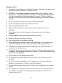
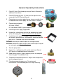
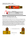
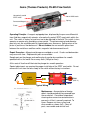
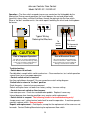
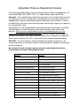
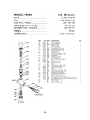
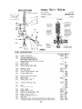
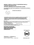
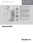
PRESSURE WASHERS
INSTRUCTIONS
Manufacturers of Quality Equipment Since 1910
PO Box 658 303 S. Main St. George, IA. 51237
Phone 888-475-3317 Fax 712-475-3490
www.siebringmfg.com Email [email protected]
TABLE OF CONTENTS
1.
TABLE OF CONTENTS
2.
3.
INTRODUCTION
OPERATOR SAFETY
4.
5.
PERSONAL SAFETY
GENERAL SAFETY
6.
7.
GENERAL OPERATING INSTRUCTIONS
TEMP CONTROL / DEMA INJECTOR
8.
9.
FLOW SWITCH
FLOW CONTROL
10. THERMOSTAT
11. PRESSURE SENSITIVE REGULATING UNLOADER – HOW IT WORKS
12.
13.
14.
15.
16.
17.
18.
19.
20.
21.
22.
23.
PRESSURE SENSITIVE REGULATING UNLOADER – SPRAY MODE
PRESSURE SENSITIVE REGULATING UNLOADER – BYPASS MDOE
UNLOADER – DECRIPTION & TROUBLESHOOTING
UNLOADER – GOLDEN EAGLE 7100
UNLOADER – CAT 7500S
UNLOADER – CAT 7534
UNLOADER – CAT 7600S
UNLOADER – CAT 7672
NOZZLES AND TIPS
TROUBLESHOOTING INDEX
TROUBLESHOOTING CONTINUED
TROUBLESHOOTING CONTINUED
24. TROUBLESHOOTING CONTINUED
25. TROUBLESHOOTING CONTINUED
26. TROUBLESHOOTING CONTINUED
27. TROUBLESHOOTING CONTINUED
28. TROUBLESHOOTING / DELIMING
29. WINTERIZING (CAT BULLETIN 083)
30. WIRE SIZE / LINE LOSS
31. PARTS INDEX
32. PARTS CONTINUED
33. PARTS CONTINUED
34. CWG 704 (BEECH) PARTS
35. WIRING DIAGRAM (HDD 3004)
36 – 38 LABELS – CAUTIONS & WARNINGS
1
SIEBRING PRESSURE WASHERS
INTRODUCTION
The general misunderstanding of a steam cleaner and hot pressure washer should be
understood.
The first generation of hot, low pressure cleaning was the steam cleaner – one to two
gallons of water heated 300°- 500°F. were discharged against dirt at 100 – 125 PSI. As
the water left the nozzle, the pressure drop caused the water temperature to drop to 212°
and much of the water temperature dissipated into the air as water vapor. Dirt and
grease were melted and dripped off of the object being washed.
The second generation of hot cleaning now uses 600 – 1200 PSI high pressure at 100°200°F. water temperature. 1.5 to 5.0 GPM are discharged against the dirt. The unvaporized hot water strikes the dirt, cutting sticky and stubborn dirt with kinetic energy
and thermal action.
Siebring Manufacturing has been in the business since 1910. Siebring was involved in
the first generation of steam cleaning equipment and has continually worked in the
development of and rugged hot, high pressure washers. In the mid sixties, Siebring was
again was on the ground floor with new developments, incorporating new designs, higher
pressure pump applications and the like.
GENERAL APPLICATIONS
Greases with heavy wax bases, animal oils in animal waste and dirt and grime are
targets for this equipment.
Engine and transmission rebuilding, heavy equipment in farm, construction, excavation
and industry are applications for easy cleaning in short periods of time.
Building, preparation for painting, special shop maintenance, cleaning animal
confinements, meat processing, chemical and petroleum industries all favor hot, high
pressure cleaning.
Construction and industrial equipment repair preparation normally requires hot pressure
washing.
A newer, specialized use for this equipment is to heat and apply de-icing and anti-icing
solutions for the aircraft industry. The same equipment is used for air frame and power
plant cleaning.
Road film – Unfortunately, road film is untouched by hot or cold pressure washing. It
must be physically contacted to break the static bond causing road film cleaning
problems.
2
OPERATOR SAFETY INSTRUCTIONS
DANGER!
DO NOT ATTEMPT TO INSTALL OR OPERATE THIS MACHINE UNTIL YOU HAVE
READ THIS MANUAL. IF YOU OR YOUR OPERATOR CANNOT READ ENGLISH,
HAVE THIS MANUAL EXPLAINED FULLY BEFORE ATTEMPTING TO OPERATE THIS
EQUIPMENT.
DANGER! (Electric Models)
THIS MACHINE MUST BE PROPERLY GROUNDED TO AVOID FATAL ELECTRICAL
SHOCK IN THE EVENT THAT IT BECOMES ACCIDENTALLY GROUNDED. HAVE
ELECTRICAL CONNECTIONS MADE BY A QUALIFIED ELECTRICIAN.
WARNING! (Electric Models)
DISCONNECT THIS MACHINE FROM ELECTRICAL SOURCE BEFORE MAKING ANY
REPAIRS.
WARNING!
THIS MACHINE IS DESIGNED TO PRODUCE VERY HIGH PRESSURE AND
TEMPERATURE AT THE GUN TIP. TO PREVENT INJURY OR DAMAGE, HOLD
CLEANING GUN SECURELY AT ALL TIMES WHEN PUMP IS IN OPERATION AND
FLUID IS BEING SPRAYED.
CAUTION!
CHECK CLEANING EQUIPMENT, REMOTE HOSE, GUN, WAND AND FITTINGS
PRIOR TO OPERATION. DO NOT OPERATE THIS MACHINE WITH A DAMAGED OR
WORN HOSE, LEAKS, OR WITH ANY COVERS OFF THAT WOULD EXPOSE BELTS,
PULLEYS OR ELECTRICAL DEVICES OR CONNECTIONS.
DANGER!
TAMPERING WITH THE MACHINE’S FACTORY PRESET UNLOADER VALVE
SETTINGS AND/OR THE PRESSURE RELIEF VALVE SETTING COULD RESULT IN A
MACHINE EXPLOSION. DO NOT ATTEMPT TO CHANGE THE SETTINGS.
DISCONTINUE USE IF A MALFUNCTION OCCURS AND CONTACT YOUR LOCAL
AUTHORIZED DISTRIBUTOR.
DANGER
DO NOT OPERATE THE UNIT WITH A MALFUNCTIONING BURNER OR BURNER
CONTROLS. INSPECT BURNER AND BURNER CONTROL OPERATION BEFORE
EACH USE. IF YOU SUSPECT A PROBLEM WITH THE BURNER, DISCONTINUE
USE IMMEDIATELY AND INVESTIGATE.
DANGER
DO NOT POINT GUN AT PEOPLE OR ANIMALS! RESULTS COULD BE FATAL! HIGH
PRESSURE WATER DAMAGES THE SKIN AND CAN INJECT WATER INTO THE
BODY.
DANGER
DO NOT REFUEL ENGINE SUPPLY TANK OR BURNER SUPPLY TANK WHILE UNIT
IS RUNNING OR HOT, ALLOW UNIT TO COOL PRIOR TO REFUELING.
3
PERSONAL SAFETY
-Wear safety glasses at all times when working on pumps.
-Wear a face shield and proper protective gear when pumping hazardous chemicals.
-Keep the work area clean, uncluttered and properly lighted. Secure and stow all unused
tools and equipment.
-Keep visitors at a safe distance form work area.
-Make the workplace child proof with padlocks, master switches and by removing starter
keys.
Washer Dangerous, Safety Panel Warns…CPSC document 5069
The U.S. Consumer Product Safety Commission has issued a warning to consumers who
use electrically powered pressure washers for cleaning milk tanks, spray tanks and other
farm equipment.
According to a federal safety alert, consumers can receive a fatal electrical shock from
pressure washers if the power cord connections become wet or an internal short exists.
Since the pressure washers are used to spray water, the power cord, washer and
consumer are often wet, and this can be fatal, especially if the machine is not properly
grounded, the report explained.
Consumers should not use adapter plugs to connect the three-wire plug to a two-prong
household receptacle without properly grounding the adaptor plug. Power cord
connections should never be allowed to lie in water.
The commission urges these precautions:
Always plug a 3-wire grounded pressure washer into a properly grounded receptacle. If
possible, use a receptacle protected by a Ground Fault Circuit Interrupter (GFCI).
If an extension cord must be used, use a heavy-duty, 3-wire properly grounded and
properly sized for the equipment being used. Keep the cord connection out of the water
and away from the item being washed.
Wear rubber-soled footwear when operating the washer.
Never cut or splice the power cord or extension cords.
Never remove the grounding plug from the power cord.
Never operate the washer after it has tripped the GFCI or circuit breaker without first
having it examined by a competent repair person.
Never allow children to operate a pressure washer and keep children away form the
washer when an adult is using it.
For more information, consumers can call the UNITED STATES CONSUMER PRODUCT
SAFETY COMMISSION hotline, 800-638-CPSC (800-638-2772).
4
GENERAL SAFETY
1.
A safety pressure relief device is installed at the factory. Removal of this device could
void the unit warranty and cause injury to personnel.
2.
WARNING – Do not pump flammable or explosive fluids such as gasoline, fuel oil,
kerosene, etc. Do not use in explosive atmospheres. The pump should only be used
with liquids compatible with the pump component materials. Failure to follow this
warning can result in personal injury and/or property damage and will void the product
warranty.
3.
Do not run the pump faster than maximum recommended speed.
4.
Do not attempt to pump at pressures higher than rated.
5.
Maximum liquid temperature is 140°.
6.
Make certain that the power source conforms with the requirements of your
equipment.
7.
Do not operate machine with belt guard, shaft guard or similar safety devices
removed.
8.
Disconnect power, stop engine and burner prior to servicing.
9.
Relieve system pressure prior to servicing.
10. Drain all liquids from system before servicing.
11. Secure discharge lines and guns before starting the pump. An unsecured line may
whip around under pressure causing personal injury and/or property damage.
12. Check hoses for weak or worn conditions before each use. Make certain that all
connections are tight and secure.
13. Periodically inspect the pump and system components. Perform routine maintenance
as required. See maintenance section in this manual, CAT pump Service Manual and
Honda manual as applicable.
14. Electric motors must be adequately grounded.
15. Do not operate a gasoline engine in an enclosed area. Be sure the area is well
ventilated.
16. Gasoline is a highly combustible fuel. The improper use, storage or handling of
gasoline can be dangerous. Never fill or touch a hot engine.
17. Do not handle a pump or motor with wet hands or when standing on a wet or damp
surface.
18. Use only pipe, hose and fittings rated for the maximum P.S.I.G. rating of the pump. If
an unloader is used, pipe, hose and fittings rated for the pressure at which the
unloader relieves itself.
5
General Operating Instructions
1.
Check Oil Level (See Honda gas engine Owner’s Manual for
additional information).
2.
Check CAT pump oil level. Oil level must be up to the red
center dot (see CAT Service Manual).
3.
Connect pressure water supply hose or immerse suction hose
in adequate clean water supply. Be sure screen is in place.
4.
Connect electrical power
A. Burner 120VAC
B. Pump Motor 220VAC (specified phase)
5.
Check engine fuel supply if applicable.
6.
Hot washer - check burner fuel tank for adequate fuel supply
(#1 or #2 Heating Oil). Do not use kerosene or bio-diesel.
7.
Installed on each washer is a square soap container box that
will accept a one gallon jug. Most products need to be diluted
prior to use. Powered soaps are unacceptable.
WARNING: Secure gun and lance prior to starting the pump.
CAUTION: Momentarily open the gun valve to relieve pressure prior
to starting the pump motor or engine.
8.
Start the pump motor.
9.
Hot washer – Ignite burner with control switch (see Beckett
AFG manual for additional burner information).
10. Soap (Dema) injector – Adjust metering screws for adequate
flow (see page 7 for additional info).
11. Temperature controller/thermostat – Adjust water temperature
to desired operating level.
12. Check pump operating pressure. Do not exceed
manufacturer’s recommended pressure. Begin cleaning.
6
TEMPERATURE CONTROL – 430027
Adjust temperature control to the desired temperature.
TEMPERATURE
CONTROL
HOT
COLD
Typical Wiring
To Flow Switch
To Control Switch
OPERATION – DEMA INJECTOR 203B / 204B
Warning: Use care when handling hazardous chemicals.
Warning: Setting the water bypass screw too far in could starve and damage the pump.
See figure below for location of water bypass screw and fine metering adjustment screw. Turn on water
supply valve. The injector may draw momentarily as the system is filling but normally will stop as the
system builds up to full pressure. To actuate injector, turn the bypass screw clockwise until product
begins to be drawn from the container. After the fluid reaches the injector, the feed rate may be
adjusted to the desired rate by turning the bypass screw. For low injection rates, it is advisable to set
the bypass screw for more injection than required; then turn the fine metering screw clockwise to
reduce injection to the desired rate. If the injector will not draw with the bypass screw full in, then the
water flow is below the range of the injector. If the injector draws with the screw full out but pressure
loss is excessive, then flow is above the range of the injector.
Fine Metering Adjustment Screw
Water By-pass Screw
7
Gems (Thomas Products) FS-925 Flow Switch
Hermetically sealed
SPDT switch
No.18 AWG Leads
Spring
Permanent Magnet
Piston
Operating Principle - A magnet-equipped piston, displaced by the pressure differential
from fluid flow, magnetically actuates a hermetically sealed, SPDT reed switch within the
unit. The switch is factory set and must not to be adjusted in the field. This switch, in turn,
operates a remote relay, providing system control. The piston metering land diameter
precisely sets the actuation point by regulating by-pass clearance. Spring return of the
piston is positive as flow decreases. Do not remove the non-metallic spacer from
between the metal base and flow switch, magnetic interference could result.
Repair Procedure - Magnet and plunger are molded as a unit. Cracks and deformation
may occur with time. Replacement parts are available.
Rough spots on the plunger and swollen plastic can be dressed down for smooth
operation with a fine metal file or emery cloth (180 grit or finer).
A thin coat of Vaseline will lubricate the plunger for smooth operation.
Special adjustments are required for proper installation of the SPDT reed switch. Do not
remove this unit from the brass body of the switch without factory instructions.
GEMS
LOAD-PAK
FLOW
SWITCH
SWITCH
LOAD
VARISTOR
(M.O.V.)
LOAD
Typical Wiring
Maintenance – Accumulation of foreign
debris should periodically be removed from
these switches. Occasional “wipe-down”
cleaning when excessive contamination is
present is all that is normally required. To
clean: Remove unit from system and
disassemble as shown (left). Clean all
parts, reassemble and reinstall unit.
8
Johnson Controls Flow Control
Model F61KD-3C / F61KD-4C
Operation – The flow switch responds to pressure exerted on the fluid paddle by the
flowing fluid. During normal operation, the circuit between the red and yellow leads
(terminals) closes when sufficient fluid flows through the piping to trip the flow switch.
When a “no flow” condition exists, the switch opens, breaking the circuit and shutting down
the burner.
Typical Wiring
Siebring Hot Washers
!
CAUTION
To
power
source
!
Not used
To thermostat
or burner
WARNING
Risk of Improper Operation
Risk of Electrical Shock
The switch is set near the minimum flow
rate. Do not set lower than factory setting
as this may result in the switch failing to
return to a “no flow” position.
Disconnect power before making any
electrical connections. Failure to follow
this precaution may result in equipment
damage, electrical shock of death
Troubleshooting:
- Switch does not activate
Possible debris caught within switch mechanism. Clean mechanism, test switch operation
several times to ensure proper operation.
- Control switch action is reversed
Has flow switch been changed? Ensure connections match wiring diagram.
-Switch fails to return to “no flow” position
Stuck flow gate – clean to free up movement
Switch setting has been set lower than factory setting. Increase setting.
- Control does not switch on flow increase
Low water pressure. Check for cracked/broken paddle. Replace if necessary.
Internal damage form freezing conditions may require switch replacement.
- Switch failure is suspect. The following check is for troubleshooting only!
Jumper across red / yellow terminal and check for machine operation. If machine operates
normally, replace switch. Remove jumper.
Repairs and replacement – Field repairs, except for the replacement of the cover can not
be made. Contact Siebring Manufacturing for replacement flow switch.
9
Honeywell Aquastat Controller L4006A
Copper Capillary Tube (to sensing bulb)
Differential Adjustment Wheel
5
Wire Terminal Screws
Set-point Indicating Dial
Operation - L4006A breaks the circuit on a temperature rise to the control setting.
High limit controller: Shuts off burner when water temperature exceeds high limit setting.
Burner restarts when temperature drops to high limit setting. Low limit controller:
Maintains minimum water temperature. Turns burner on at temperature setting, less
differential. Differential Adjustment wheel, typically used on boiler applications. Factory
set to 5°.
Checkout - Check to make certain that the Aquastat Controller has been installed and
adjusted properly. Put the system into operation and observe the action of the device
through several cycles to make certain that it provides proper control of the system as
described in the Operations section. Further adjustments can be made as required.
Typical Wiring
To Burner
5
To Switch
L4006A
Flow Control
10
Pressure Sensitive Regulating Unloader
This type of unloader may be referred to as a “Trapped Pressure” type or just
"Pressure" type. This type of valve opens to bypass when it senses the pressure
build up of the pump output having nowhere to go. The main characteristic of this
most commonly used valve is how it traps the pressure in the hose when the trigger
of the pressure gun is released and unloading excess pressure between the pump &
unloader.
The disadvantage of this type of valve is the spike of pressure felt by the operator
and sprayer/pressure washer components when the trigger is again squeezed. This
creates a "kickback" effect on the gun/wand so be careful when using ladders or
other types of access equipment.
When your system uses a trigger gun that stops the water flow from the pressure
pump the unloader valve must be employed. Understand that when the trigger of the
gun is released the water flow to the nozzle is interrupted. The power source and the
pressure pump are still running, Without some pressure washer system safety device
the water would have nowhere to go, building pressure till disaster ensued.
Enter the Unloader Valve. The most basic function of the unloader is to act as a
"traffic cop" to the water flow in your system as soon as it senses "pressure build".
When the “Pressure Build” condition is met the unloader will then actuate the piston
assembly to divert the water flow toward the bypass port. When this is occurring the
pump is said to be in "bypass mode" and the unloader valve is said to be "cycling".
This scenario ends when the trigger is squeezed alerting the unloader valve to
redirect the flow to the gun and high pressure nozzle once again. While this may
seem to be problem solved it is not without risks. When the water flow is in bypass
mode, new cool water is not entering the system. The moving parts in the pump are
creating friction which produces heat that is transferred to the water flow in the
bypass loop. Since a limited amount of water is in bypass this transfer of heat can
occur quickly. If the pump has been in the bypass mode long enough to build an
excessive amount of heat, thermal shock may occur if cold water is suddenly
introduced into the system.
Most pumps are designed to handle water temperatures of 160° F. When the water
in bypass climbs above 160°F damage to the pump will begin. Damage can occur to
the pump packings, plungers and seals and even to the short bypass hose in
external bypass setups. It is a good idea not to leave a pump in bypass mode for
more than 2-3 minutes, by simply squeezing the trigger gun you will introduce new
cool water into the system.
11
Pressure Sensitive Regulating Unloader
Spray Mode
Gun trigger is depressed with gun in
use. Pump flow enters from the left
of the diagram (inlet port), passes
through the unloader, out of the
outlet port, to the gun.
Inlet Port
Pump
Piston Assembly
CAUTION: A minimum bypass of 5 10% of the UNLOADER RATED
FLOW CAPACITY is required for
proper unloader performance.
Outlet Port
Check
Valve
Flow
Additional bypass fluid
may be the excess
pressure - the difference
between the pump output
and the unloader setting.
Bypass Port
5 - 10 %
Min.
Bypass
12
To
Gun
CAUTION: If the entire output is
directed through the unloader (zero
by-pass) the cushioning feature of
the by-pass liquid is eliminated and
the unloader can malfunction and
wear prematurely.
Pressure Sensitive Regulating Unloader
Bypass Mode
WARNING: DO NOT
OPERATE IN BYPASS
MODE LONGER THAN
2 MINUTES.
Pump
CAUTION: A minimum bypass of 5 10% of the UNLOADER RATED
FLOW CAPACITY is required for
proper unloader performance.
Piston Assembly
Inlet Port
Gun trigger valve is closed, gun is
not in use. Pump flow enters from
the left of the diagram (inlet port),
dead ends against output check
valve, overcomes the spring
pressure holding the piston
assembly and is forced down
through the bypass port.
Outlet Port
Check
Valve
Flow
To
Gun
CAUTION: If the entire output is
directed through the unloader (zero
by-pass) the cushioning feature of
the by-pass liquid is eliminated and
the unloader can malfunction and
wear prematurely.
Bypass Port
Bypass
13
Adjustable Pressure Regulating Unloader
The following Unloader models are used on Siebring Pressure Washer applications: Cat
Pump model 7500, 7534, 7600 & 7672. J.E. Adams Golden Eagle model 7100.
Operation – The unloader holds established system pressure in the discharge line when
the trigger gun is closed, solenoid valve is closed (gate) valve is closed or the nozzle is
clogged, bypassing the unrequired flow between the pump and the unloader. It returns
to established system pressure without delay upon squeezing the trigger gun or opening
the solenoid (gate) valve.
When properly set the unloader protects the pump from pressure extremes associated
with obstructions in the discharge line, while maintaining the established system
pressure. When no flow is required by the system, the unloader by-passes all the
system flow and relieves the load on the pump. Pressure is held in the discharge line
(between the unloader and the gun) ready for a quick return to high pressure operation.
Note: A minimum bypass of 5-10% is necessary for the unloader to operate properly.
CAUTION – If the entire output is directed through the unloader (zero by-pass) the
“cushioning” feature of the by-pass liquid is eliminated and the unloader can malfunction
or wear prematurely.
Do not leave the unit running in by-pass mode for extended periods of time.
Overheating of the pump manifold could result.
Problem
Solution
Unloader Cycles
Check for leak downstream of unloader
Worn o-ring or check valve
Air in system, poor connection
O-ring in gun worn
Liquid leaking from bottom fitting
O-ring for fitting cut or worn
O-ring for seat cut or worn
Liquid leaking form middle
O-ring for piston cut or worn
O-rings for piston stem cut or worn
Unloader will not come up to pressure
Not properly sized for system pressure
Foreign material in unloader. Clean filter.
Piston stem o-rings worn
Nozzle worn
Insufficient flow to pump
Extreme pressure spikes
Adjusting nut turn completely into unloader
Restricted by-pass or no by-pass
System flow exceeds unloader rating
14
GOLDEN EAGLE 7100 UNLOADER
800 - 2000 PSI
15
16
17
18
19
IMPORTANT PARTS FOR SIEBRING WASHERS
Model
P.S.I.
G.P.M.
TIP / NOZZLE
DEMA
INJECTOR
CWH704
700
4.0
9 TIP
204B
CDD1003 / CWH103
1000
3.0
6 TIP
203B
CDD1204
1200
4.0
7 NOZZLE
204B
CDD1503
1500
3.0
6 NOZZLE
203B
CDD2004 / CW2004
2000
4.0
5 NOZZLE
204B
HDD1003 / HHP180
1000
3.0
6 NOZZLE
203B
HDD1204 / HHP1204
1200
4.0
7 NOZZLE
204B
HDD1503 / HHP1503
1500
3.0
4.5 NOZZLE
204B
HDD2004 / HHP2004
2000
4.0
5 NOZZLE
204B
GAHP180
1000
3.0
6 NOZZLE
204B (OPT.)
MWG180
1000
3.0
6 NOZZLE
204B (OPT.)
MWG1204
1200
4.0
7 NOZZLE
204B (OPT.)
MWG2004
2000
4.0
5 NOZZLE
204B (OPT.)
5
10
3
1
2
8
4
7
6
1.
2.
3.
4.
5.
Typical Installation,
Cold Pressure Washer
Hose Quick Coupler (female)
Unloader
CAT Pump
CAT Pump Manifold
Pressure Gauge
9
6. By-pass Hose
7. Solution Injector
8. Garden Hose connector w/screen
9. ⅜” Hose
10. Connector plug (male)
20
TROUBLESHOOTING INDEX
A. PRESSURE DROP (NEW INSTALLATION)
B. PRESSURE DROP AFTER MACHINE IS IN SERVICE
C. PULSATION IN HOSE
D. UNLOADER CYCLES RAPIDLY
E. FLOW SWITCH FAILS
F.
MOTOR STOPS AFTER SHORT DURATION
G. PUMP MOTOR FAILS TO START
H. PUMP MOTOR FAILS TO STOP
I.
AUTOMATIC PUMP AND BURNER SHUT DOWN SYSTEM
J.
BURNER MOTOR FAILS TO START
K. BURNER MOTOR FAILS TO STOP
L.
BURNER FAILS TO IGNITE
M. INTERMITTENT FLAME
N. WATER LEAKING FROM HEATING COIL COMPARTMENT
O. PRESSURE FAILS TO DROP WHEN GUN VALVE IS CLOSED
P. LIQUID IN GAUGE
Q. PUMP OIL DISCOLORATION
R. WATER OR OIL LEAKING FROM BOTTOM OF PUMP
S. SOLUTION INJECTOR FAILURE
T.
WATER SUPPLY AND CONTAMINATION
U. LEAKING RELIEF VALVE
V. FREEZING OF PUMPS AND COILS
21
TROUBLESHOOTING
A.
PRESSURE DROP (new installation)
1.
Inadequate water supply.
Adjust water regulator on intake (turn screw downward). Increase water
supply to 30 P.S.I. minimum.
2.
Improper nozzle size.
Consult manufacturer.
3.
Open solution injector.
Close injector solution supply valve when not in use.
B.
PRESSURE DROP AFTER MACHINE IS IN SERVICE
1
Unloader cup or wall scored or worn.
Install a rebuild kit or replace unloader.
2.
Pump piston cup worn.
Install rebuild kit.
3.
Damaged piston cylinders.
Install water sand filter.
4.
Worn nozzle.
Replace with correct or same size nozzle.
5.
Air leak to solution injector.
Close solution injector supply valve or replace hose.
6.
Loose pump drive belt (if applicable).
Adjust tension to achieve ½” movement of belt at mid-point.
7.
C.
Clogged pick-up in tank. Clear clog.
PULSATION IN HOSE (usually accompanied by a drop in pressure).
1.
Open solution injector.
Close solution injector supply valve or fill solution tank.
2.
Water supply shortage or clogged pick-up in tank.
Increase pump water supply, clear clogged pick-up..
Clean filter inside pressure regulator or screen in intake connection.
3.
Defective piston cup.
Replace piston cups.
4.
Stuck unloader piston
5.
Obstruction in nozzle causing “false” unloader functions.
22
TROUBLESHOOTING
D.
(CONTINUED)
UNLOADER CYCLES RAPIDLY
1.
Rapid in-out movement of unloader plunger (units without complete shutoff).
Leak in high pressure line, gun leak, or a “weep” type gun is in use.
Defective poppet (nylon plunger in in lower portion of unloader). Poppet may
be deformed or sticking. Replace or dress smooth with fine emery cloth.
Bad unloader cup, seals or o-rings – replace.
Scored unloader cup bore – replace unloader.
Plugged nozzle – clean/replace nozzle.
E.
FLOW SWITCH FAILS
1.
Burner fails to start/stop when gun is shut off/on (mobile wash and partial
shut off models).
The swing gate (paddle) located in the water stream is stuck, loose or
clogged with debris. Remove and clean. Replace if defective.
F.
MOTOR STOPS AFTER SHORT DURATION
1.
Thermal Overload tripped.
Check for low voltage, excessive drive belt tension, extension cord not
adequate gauge for length or stuck starter switch.
2.
Excessive operating pressure.
Reduce pump operating pressure to manufacturers recommendation.
3.
Defective motor start switch (inside of motor) or motor fails to reach
operating speed & pressure.
Have an electrician verify motor condition.
G.
PUMP MOTOR FAILS TO START
1.
No Power.
Check plugs, fuses and cords for contact.
2.
Defective flow switch (complete shut-off models).
Free the magnetic plunger within the flow switch. Remove plunger and coat
with Vaseline.
3.
Thermal overload on motor tripped out (if so equipped).
Check for low voltage on power supply, extension cord not adequate gauge
for length, check belt for excessive tension, and check pump for excessive
pressure.
4.
Defective load pak.
Try manual override switch on electrical connection box.
5.
Excessive pressure in discharge hose.
Open gun valve, check unloader.
23
TROUBLESHOOTING
H.
(CONTINUED)
PUMP MOTOR FAILS TO STOP
1.
Flow switch on “complete shut-off units” plunger sticks.
Free the magnetic plunger within the flow switch. Remove plunger and coat
with Vaseline. Check for ½” non-metallic spacer in place between mounting
area and switch body (see page 8 for more info.).
2.
Air in coil or air in piping of facility.
Remove air cushion from unit, service lines and water supply (bleed air from
system).
3.
Defective operating switch.
Check for welded motor starter contacts or line switch.
I.
AUTOMATIC PUMP AND BURNER SHUT DOWN SYSTEM
1.
Unit fails to stop when gun is closed (shut).
Check for leaks in system and repair if required.
Disconnect wires from “switch” terminals on load pak in electrical box.
If unit stops, inspect flow switch for foreign material on piston. If piston is free,
switch is defective or improperly adjusted.
If unit continues to run, disconnect wires from “load” terminals on load pak in
electrical box.
If unit stops, load pak is defective.
If unit continues to run, motor starter is defective.
Stuck plunger on flow switch – remove burrs and residue with fine emery
cloth. Coat plunger with Vaseline and reinstall.
2.
Unit will not stop when gun is closed.
Be sure there is no electrical power to the unit and no fuses are blown.
Check to be sure the overload is not tripped. If tripped, press reset button.
Make sure water supply is on and is sufficient (30 P.S.I. minimum). Check for
kinked feed hose.
Use an insulated jumper wire and momentarily jumper the “switch” terminals
on load pak (electrical box). See item 1 above.
If unit is being used on a pipe line system, delayed starting can be caused by
air in the piping. Pipe must be completely full of water.
Check for dirt or foreign matter in the filter or screens preventing adequate
water flow through the flow switch.
24
TROUBLESHOOTING
J.
(CONTINUED)
BURNER MOTOR FAILS TO START
1.
Check burner switch on side of burner.
Up is “on” may be defective
2.
Water temperature control stuck “open.”
Jumper wire terminals on temp switch momentarily. If burner starts, replace
temperature switch.
3.
Defective flow switch.
Jumper wire terminals on flow switch momentarily. If burner starts, replace
flow switch.
4.
Overload button tripped on burner motor.
Depress button to reset. If problem continues, consult electrician.
K.
BURNER MOTOR FAILS TO STOP
1.
Check burner switch.
Down is “off” may be defective.
2.
Water temperature control stuck “closed.”
Disconnect one wire of the temperature control switch to see if control is the
problem.
L.
BURNER FAILS TO IGNITE
1.
Empty or low fuel supply.
Replenish fuel supply.
2.
Plugged filter or nozzle.
Replace filter cartridge and appropriate nozzle.
3.
Air leaks or air in oil line.
Bleed pump. Check oil line fittings for air leaks.
4.
Weak ignitor/transformer.
With an insulated screwdriver, draw a spark across the ignitors,
spark should be ¾” to 1”. At ½” replace ignitor transformer.
25
TROUBLESHOOTING
M.
(CONTINUED)
INTERMITTENT FLAME
1.
Dirty oil supply, water in fuel tank.
Check filter and nozzle for cleanliness. Clear tank and filter of water.
2.
Low oil supply
Raise fuel level in supply tank.
Oil line cracks and/or loose connections.
Tighten or replace parts to prevent air bubbles (suction leaks) in oil line.
N.
WATER LEAKING FROM HEATING COIL COMPARTMENT
1.
Drips
Condensation drips (several per minute) are normal.
2.
Steady stream leak.
Cracked coil, needs repair or replacement.
O.
PRESSURE FAILS TO DROP WHEN GUN VALVE IS CLOSED
1.
Defective unloading valve.
Clean or replace.
2.
Leak in gun, fittings, hose or coil under high pressure.
Repair leak.
P.
LIQUID IN GAUGE
1.
Gauge is liquid type, oil is normal.
Replace gauge if empty or low on oil.
2.
Water leaking from gauge.
Ruptured mechanism (Bourdon tube). Replace gauge assembly.
Q.
PUMP OIL DISCOLORATION
1.
White foam – water in oil.
Drain and replace with CAT pump oil or temporarily with S.A.E. 40 nondetergent motor oil. Faulty intake seals from wear or freezing – replace as
required.
2.
Brown foam – rust & water.
Pump may need rebuilding if pressure is dropping and a rapid reoccurrence of foam in sight glass after several hours of operation with fresh
oil.
26
TROUBLESHOOTING
R.
(CONTINUED)
WATER OR OIL LEAKING FROM BOTTOM OF PUMP
1.
Water – noticeable amounts.
Inlet water seals on pistons failing. See appropriate pump manual.
Cracked pump manifold from freezing – replace.
2.
Oil – noticeable amounts.
Leak and failure of oil seals on pistons. Return to Siebrings for repair
(notify to verify condition).
S.
SOLUTION INJECTOR FAILURE
1.
Improper water supply to pump.
Turn water bypass screw counter clockwise. This will decrease the
solution draw, increasing the water supply to the pump.
2.
Improper metering screw adjustment.
Metering screw turns left to increase solution flow. Do not exceed 5 turns
form full closed position. Try to achieve flow of ½” per second for most
thick detergents passing through the plastic solution feed tube.
3.
Plugged strainer on solution tank.
Dirty screen in tank filter assembly, or undissolved powdered soap.
4.
Water back feeding to solution supply tank through injector.
Dirty, deformed or missing check ball in injector metering assembly.
Weak ball check spring.
Bad washer on ball seat in intake on injector.
T.
WATER SUPPLY AND CONTAMINATION
1.
Sand from private wells.
Allow water sample to stand in clear glass bottle over night to observe
sediment. Add line filter if in doubt.
2.
High sulphur.
Brass parts may need replacement when used in high concentrations of
sulphur.
3.
Hard water
On hot washers, if water tests to 90 grains of hardness or above, use of a
water softener is required for improved coil life and prolonging the time
between cleaning and/or de-liming.
27
U.
LEAKING RELIEF VALVE
1.
Foreign matter may be caught in the valve seat.
Remove from machine, disassemble. Soak in vinegar overnight.
V.
FREEZING OF PUMPS AND COILS
1.
Water frozen in pumps and coils will void warranty.
Winterizing mix = 50/50 mix of water and anti-freeze or 50/50 mix of water
and methanol (see winterizing steps on page 26 of this manual).
If freezing conditions are suspect, always intake approximately 1 gallon of
winterizing mix or until mix is expelled for gun discharge.
In hot units, blow through unit coils with compressed air to avoid freezing
(large replacement cost).
DELIMING INSTRUCTIONS FOR HOT WATER COIL
CAUTION: Do not use this procedure on a coil that is completely plugged. For severe
cases, call Siebring Manufacturing.
1.
2.
Disconnect the steam hose at the unit.
In a plastic container, put 2 ½ gallons of water and into this very slowly add one gallon
of muriatic acid.
CAUTION: ALWAYS ADD THE ACID TO THE WATER, NEVER THE WATER
INTO THE ACID
3.
4.
5.
6.
7.
8.
Take a short piece of garden hose with a male garden hose fitting on one end.
Put one gallon of clear water in another container for use later
Start pump and connect this short hose to the water inlet fitting and suck in the acid
solution.
Immediately suck in the one gallon of clear water to flush the acid out of the pump only.
Let the unit stand for 10 – 15 minutes – no longer.
Connect the regular water supply to the unit and start the pump and flush thoroughly
with clean water.
28
WINTERIZING A PUMP (CAT Pump Tech Bulletin 083)
Standard Shut Down
• Flush pump and chemical injector with fresh water.
• Turn off power supply
• Squeeze trigger gun to relieve pressure
• Disconnect inlet and discharge plumbing
System Flush (Winterizing)
• Connect a short 4 foot hose to the pump inlet and place the other end of the
hose in a container with 50% water and 50% antifreeze, or 50% water and 50%
methanol.
• Start the unit and run until antifreeze flows out of the discharge of the pump
and hose reel.
• Shut off unit and disconnect the hose from the pump inlet.
• Store unit (do not install plugs in the inlet and discharge port).
• Cover to protect from severe elements.
Restarting System
• Turn regulator/unloader setting to lowest pressure point, or open high pressure
gun.
• Check crank case oil level and purity.
• Reconnect the liquid supply hose, discharge hose and allow liquid to flow
through pump for 2 – 3 minutes (hot washer models).
• Check for leaks at all plumbing connections.
• Turn crankshaft by hand initially. If free moving, start power.
• Gradually reset regulator/unloader in small increments to desired system
pressure and resume operation.
• Follow your established maintenance cycle or the standard Preventative
Maintenance Check List in the pump service manual.
29
Wire Size for 115 & 230 Volt Single Phase Circuits
Distance – Motor to Fuse or Motor to Meter Box
MOTOR
HP
100 FT.
200 FT.
300 FT.
500 FT.
115V
230V
115V
230V
115V
230V
115V
230V
1/4
# 14
# 14
# 10
# 12
#8
# 10
#6
#8
1/3
# 12
# 14
# 10
# 12
#6
# 10
#4
#8
1/2
# 10
# 12
#8
# 10
#6
#8
#4
#6
3/4
# 10
# 12
#6
# 10
#4
#8
#2
#6
1
#8
# 10
#6
#8
#4
#6
#4
1½
#4
# 10
#0
#8
#6
#4
2
#8
#6
#4
#2
3
#8
#6
#4
#2
5
#6
#4
#2
#0
SUPPLY WATER LINE
PRESSURE LOSS
HOSE FRICTION LOSS PSI
PER 100 FT.
WATER
GPM
1/8
1/4
3/8
1/2
3/4
1/4
3/8
1/2
5/8
3/4
3
270
60
14
4.5
1.1
380
50
13
4.0
1.5
4
345
105
25
8.3
1.9
90
23
7.0
2.7
3
420
150
36
12
2.8
130
34
10
4.0
30
1
1.0
PARTS CWG704, CDD1003 - CDD2004
CD1
CD2
CD3
CD4
CD5
CD6
CD7
CD8
CD9
CD10
CD11
CD12
CD13
CD14
CD15
CD16
CD17
CD18
CD19
CD20
CD21
CD22
CD23
CD24
CD25
CD26
CD27
CD28
CD29
CD30
CD31
CD32
CD33
CD34
CD35
CD36
CD37
HANDLE
MOTOR – SPECIFY SIZE BY HP
MAGNETIC STARTER – 1200 PSI MACHINES AND HIGHER
TOGGLE SWITCH – 1000 PSI MACHINES AND LOWER
GAUGE
UNLOADER – SPECIFY WASHER MODEL
PUMP – SPECIFY MODEL
BYPASS HOSE
¼” BALL VALVE
BRACKET FOR ¼” BALL VALVE
SOAP BOX
DEMA INJECTOR 203B 200 -1000 PSI 204B – 1200 - 2500 PSI
GARDEN HOSE FITTING
SCREEN FOR INSIDE GARDEN HOSE FITTING
25MP – MALE PLUG QUICK COUPLER – OUTLET HOSE
25FS – FEMALE SOCKET QUICK COUPLER
⅜” HOSE – SPECIFY LENGTH
GUN – 1000 PSI AND LOWER
18” EXTENSION
TIP – REQUIRES BRASS CAP
BRASS CAP FOR TIP
GUN – 1200 PSI AND HIGHER
WAND – ¼” BLACK PIPE
NOZZLE – THREADED (STRAIGHT OR 15°)
HANDLE BAR GRIP
WHEELS – SPECIFY TYPE/SIZE
SS FEMALE SOCKET QUICK COUPLER
SS CAP FOR TIP
12” EXTENSION
GUN JD9-C
PUMP PULLEY, 8”
MOTOR PULLEY, 2.5” X ¾”
BELT (BX35)
BELT GUARD
5.5 HP HONDA ENGINE
HUB CAP, PUSH TYPE
BEECH HANDLE
31
CD1
CD3
CD2
CD11
CD4
CD26
CD5
CD7
CD9
CD12
CD10
CD15
CD14
CD8
CD6
CD13
32
CD23
CD22
CD17
CD25
CD18
CD30
CD24
CD19
CD29
CD15
CD16
CD21
CD20
33
CD28
CD27
CWG704 (Beech) Parts
(Additional and/or similar parts may be listed on previous pages)
CD34
CD32
CD37
CD33
CD31
CD5
CD8
CD6
CD12
CD34
CD13
CD14
CD26
CD7
CD36
CD9
CD11
CD5
CD6
CD7
GAUGE, 1500 PSI
UNLOADER, ADAMS 7100
430 CAT PUMP
CD8
CD9
CD11
CD12
CD13
CD14
CD31
CD32
CD33
CD34
CD35
CD36
CD37
BYPASS HOSE
¼” BALL VALVE W/BRACKET
SOAP BOX
DEMA INJECTOR, 204B
GARDEN HOSE FITTING (SEE PAGE 29)
SCREEN FOR GARDEN HOSE FITTING (SEE PAGE 29)
PUMP PULLEY, 8”
MOTOR PULLEY, 2.5” X ¾”
BELT (BX35)
BELT GUARD
5.5 HP HONDA ENGINE
HUB CAP, PUSH TYPE
BEECH HANDLE
34
HHD3004
Typical Wiring, Hot Pressure Washer
FLOW
SWITCH
110V
220V
RELAY
1
5
2
PUMP
6
BURNER
OFF
1L1
3L2
5L3
CONTROL SWITCH
SQUARE D
3
2T1
4T2
7
4
8
6T3
RESE
T
PUMP MOTOR
BURNER
WATER TEMP
CONTROLLER
35
CAUTION
HOT
FUEL TANK
USE NO. 1 OR NO. 2
HOME HEATING OIL
Hot Washers, SG-10
No Kerosene, no Bio-mix over 10 %
Hot Washers, SG-10
CAUTION
TO COMPLETELY PROTECT FROM
FREEZING, BLOW ALL WATER OUT
WITH AIR PRESSURE. THEN SUCK IN
1 QUART OF ANTIFREEZE WITH A
SHORT INTAKE HOSE. THEN BLOW
AIR INTO INTAKE VALVES UNTIL
ANTIFREEZE APPEARS AT THE END
OF DISCHARGE HOSE.
All Sprayers & Pressure Washers
CAUTION
CAUTION
Do not run pump
with gun closed
for more than 2
minutes.
OPERATE ONLY IN WELL
VENTILATED AREA UNLESS
UNIT IS VENTED TO OUTSIDE
All Sprayers & Pressure Washers
Gas Engine Units & Hot Washers
36
! WARNING
HIGH PRESSURE WATER
INJECTION HAZARD EXISITS.
Do not allow water to contact the
human body. Under high pressure,
it will penetrate the skin and can
cause serious infection or injury.
This unit to be operated only by
competent, cautious personnel.
All
WARNING
USE EXTREME CARE WHEN OPERATING THIS
MACHINE. DO NOT ALLOW WATER TO CONTACT
THE HUMAN BODY BECAUSE WATER UNDER HIGH
PRESSURE IS DANGEROUS. IT WILL PENETRATE
SKIN AND CAN CAUSE SERIOUS INFECTION OR
INJURY.
UNIT TO BE OPERATED ONLY BY
COMPETENT, CAUTIOUS PERSONNEL.
All
37
THIS ACCESSORY IS TO BE USED
FOR BLOWING THE WATER OUT OF
THE COIL IN FREEZING CONDITIONS
SO THE COIL DOES NOT FREEZE.
THE COIL MAY BURST IF EXPOSED TO
FREEZING CONDITIONS, VOIDING ALL
WARRANTIES.
Note: Remove Valve Stem
Hot Washers, SG-10
WATER DRIPPING FROM THE FRONT OF THE
MACHINE IS NOT A LEAK IN THE COIL. IT IS
NORMAL AND CAUSED BY CONDENSATION.
SIEBRING MANUFACTURING, INC.
GEORGE, IOWA
BACK FLUSH ASSEMBLY
THIS ACCESSORY IS TO BE USED FOR
FLUSHING THE PUMP AND ASSOCIATED
PLUMBING, AND FOR TROUBLESHOOTING
AND LEAK CHECKING THE SYSTEM.
Hot Washers, SG-10
Mr. Drench & Fox Sprayers
38