1
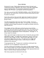
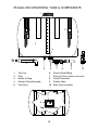
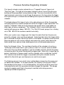
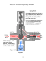
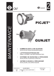
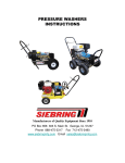
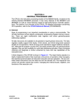
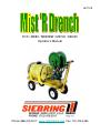
08/17/09
FOX / MD83 / MD83BW / MD100 / MD200
Operator’s Manual
Phone: 888-475-3317 www.siebringmfg.com Fax: 712-475-3490
TABLE OF CONTENTS:
1.
Cover
2.
3.
Table of Contents
Warranty / Shading Information
4.
5.
Features
Accessories
6.
7.
General Safety
Consumer Product Safety Commission Warning
8.
9.
Precautions / Back-flush Procedures
Operating Instructions / Cordage Chart
10. Operating Instructions (continued)
11. How it works
12. Tank & Components
13. Tank & Component Diagram
14. Unloader Description
15. Unloader Diagram – Spray Mode
16. Unloader Diagram – By-pass Mode
17. Pump / plumbing – By-pass mode
18. Pump / plumbing – Re-circulate mode
19. Flow Diagram – Pump / Plumbing
20. Flow Diagram – Typical system
21. Troubleshooting Index
22. Troubleshooting (continued)
23. Troubleshooting (continued)
24. Troubleshooting (continued)
25. Troubleshooting (continued) / Winterizing
26. Parts List
27. Parts Diagrams
28. Parts Diagrams (continued)
29. Warning & Caution Labels
30. Warning & Caution Labels (continued)
2
CONDITION OF SALE
SIEBRING MANUFACTURING, INC.
GEORGE, IA 51237
Pursuant to Magnuson-Moss Warranty Federal Trade Commission Improvement Act
P.L. 93-637, 88 STAT.2183-2193; U.P.C. 2301-2312 (Jan. 4, 1975), the following
limited warranty will now replace all prior warranties issued by Siebring
Manufacturing, Inc.
We warrant the equipment manufactured by us to be free from defects in material
and workmanship under normal use and service, our obligation under this warranty
being limited to replacing at our factory any product, or parts thereof, which shall
within one year after delivery thereof to the original purchaser be returned to us with
transportation (UPS Ground) charges prepaid, and which our examination shall
disclose to our satisfaction to have been thus defective. We neither assume nor
authorize any other person to assume for us any other liability in connection with
such equipment. “Overnight”, “Next Day” or any shipping method other than UPS
Ground will the responsibility of the customer. This warranty shall not apply to any
equipment which shall have been repaired or altered outside of our factory in any
way so as to affect its stability and reliability, nor which has been subject to misuse,
negligence or accident, nor to any equipment, which shall have been operated
beyond factory rated capacity. We shall not be liable for consequential damages
caused by defective materials, equipment or parts warranted by their respective
manufacturers.
Any implied warranty (including the warranty of merchantability), to the extent
permitted by law, is excluded.
We will not grant any allowance for any repairs or alterations without written approval
of an executive officer, and we reserve the right to make changes in design, or to
make additions to, or improvements in, our products without imposing any
obligations upon the company to install them on products previously manufactured.
Shading:
Continental Products Company’s “Kool Ray” liquid shading products are the only brands
authorized for use in the Siebring “Mist R’ Drench” and “Kruser” line of sprayers.
DO NOT USE LATEX PAINT!
Use of unauthorized products can damage the sprayer pump and components and will
void the warranty.
Prior to applying shading, install a 0° tip and a 50 mesh screen (not included) in the filter
bowl assembly.
3
MD83 / MD83BW Features & Accessories
2
1
3
4
11
5
12
6
7
1.
2.
3.
4.
5.
6.
7.
8.
9.
10.
11.
12.
8
9
10
4
Tank return Quick Disconnect
Bypass Valve
Liquid filled gauge
Oil filler cap
Oil sight glass
Brake to prevent unwanted spool run-off
Removable crank for emergency winding
Electric rewind
Rewind switch
Align arrows for manual unwind
Tank shut-off valve
Included Accessories (see next page)
2 Spray guns
2 - 18” & 1 - 12” wand
1 - 12” curved (hook) extension
3 piece misting tip & water breaker
Back-flush fitting
0° & 15° pressure nozzles
5
8
4
4 5 6
2
10 11 12
2
9
3
3
Small water breaker
18” extension (2)
Gun (2)
Cap
0° Tip
15° Tip
1.
2.
3.
4.
5.
6.
12” Extension
Backflush fitting
12” Hook
12. Brass Strainer
11. Core
10. Disk
9.
8.
7.
Fox, MD83, MD83BW, MD100, MD200 Included Accessories:
7
1
GENERAL SAFETY
1.
WARNING – Do not pump flammable or explosive fluids such as gasoline, fuel oil,
kerosene, etc. Do not use in explosive atmospheres. The pump should only be used
with liquids compatible with the pump component materials. Failure to follow this
warning can result in personal injury and/or property damage and will void the product
warranty.
2.
Do not run the pump faster than maximum recommended speed.
3.
Do not attempt to pump at pressures higher than rated, motor damage may result.
4.
Maximum liquid temperature through pump is 140°.
5.
Make certain that the power source conforms with the requirements of your equipment
(see cord chart on page 8).
6.
Do not operate machine with belt guard, shaft guard or similar safety devices
removed.
7.
Prior to servicing, disconnect power, stop engine.
8.
Relieve system pressure prior to servicing.
9.
Drain all liquids from system before servicing.
10. Secure quick couplers on lines and guns before starting the pump. A loose quick
coupler may cause a hose whip around under pressure causing personal injury and/or
property damage.
11. Check hoses for weak or worn conditions before each use. Make certain that all
connections are tight and secure.
12. Periodically inspect the pump and system components. Perform routine maintenance
as required. See maintenance section in this manual, CAT pump Service Manual and
Honda engine manual as applicable.
13. Electric motors must be adequately grounded.
14. Do not operate a gasoline engine in an enclosed area. Be sure the area is well
ventilated.
15. Gasoline is a highly combustible fuel. The improper use, storage or handling of
gasoline can be dangerous. Never fill or touch a hot engine.
16. Do not handle a pump or motor with wet hands or when standing on a wet or damp
surface.
17. Use only pipe, hose and fittings rated for the maximum P.S.I.G. rating of the pump. If
an unloader is used, use pipe, hose and fittings rated for the pressure at which the
unloader bypass operates.
6
WASHERS DANGEROUS, SAFETY PANEL WARNS
The U.S. Consumer Product Safety Commission has issued a warning to
consumers who use electrically powered pressure washers for cleaning milk tanks,
spray tanks, and other farm equipment.
According to a federal safety alert, consumers can receive a fatal electrical shock
from pressure washers if the power cord connections become wet or an internal
short exists.
Since pressure washers are used to spray water, the power cord, washer and
consumer are often wet, and this can be fatal, especially if the machine is not
properly grounded, the report explained.
Consumers should not use adaptor plugs to connect the three-wire plug to a twoprong household receptacle without properly grounding the adaptor plug. Power
cord connections should never be allowed to lie in water.
The commission urges these precautions:
- Always plug a three-wire grounded pressure washer into a properly grounded
receptacle. If possible, use a receptacle protected by a ground fault circuit
interrupter (GFCI).
- Check all flexible cords, plugs and sockets before each use. Replace any
damaged items.
- If an extension cord must be used, use the heavy-duty three-wire, properly
grounded type, and keep the power cord connection out of the water and away from
the item being washed.
- Wear eye protection when using sprayers or pressure washers.
- Wear rubber-soled footwear when operating the washer.
- Never cut or splice the power cord or extension cords.
- Do not leave hoses or cords where they can be run over and damaged.
- Never remove the grounding prong from the power cord plug.
- Never operate the washer after it has tripped a ground fault interrupter or circuit
breaker without first having it examined by a competent repair person.
- Never allow children to operate a pressure washer, and keep them away from the
washer when an adult is using it.
- Never spray the cleaner at yourself or others. The pressure can cause the water
and cleaner to blast under the skin.
- Never start the washer until you have checked to make sure all coupler hose
connections are in place and locked.
FOR MORE INFORMATION, CONSUMERS CAN CALL THE CPSC TOLL-FREE
HOTLINE, 800-638-CPSC.
7
MD83 PRECAUTIONS
ALWAYS - RINSE AND FLUSH OUT THE MD83 AFTER EACH USE.
ALWAYS - DRAIN ANY REMAINING FLUIDS FROM THE SPRAYER TO
PROTECT IT FROM FREEZING.
ALWAYS - READ AND FOLLOW ALL DIRECTIONS OF THE CHEMICAL
MANUFACTURER (CHECK MSDS).
ALWAYS - PUT FRESH, CLEAN WATER IN THE MD83 AND TEST THE
SPRAYER FOR PROPER OPERATION BEFORE ADDING ANY SPRAYS.
ALWAYS - WEAR PROTECTIVE GEAR WHEN MIXING OR APPLYING ANY
CHEMICALS. THIS INCLUDES MASK, RESPIRATOR, GLOVES,
GOWN, ETC.
ALWAYS - MAINTAIN THE MIST’R DRENCH IN GOOD REPAIR. THIS
WILL HELP PREVENT LEAKS, ETC. AND ADD TO THE LIFE OF THE
MACHINE.
BACKFLUSH PUMP FITTINGS FOR MIST’R DRENCH
PARTS INCLUDED:
1 – 50MP QUICK COUPLER
1 – GARDEN HOSE SCREEN
1 – ¾ X ½ SWIVEL ADP. (S11) GARDEN HOSE FITTING
HOW TO USE
**TANK MUST BE EMPTY**
1. DISCONNECT BLACK RUBBER SUCTION HOSE FROM TANK AT QUICK
COUPLER
2. SNAP SUPPLIED FITTINGS INTO HOSE QUICK COUPLER
3. ATTACH GARDEN HOSE TO FITTING
4. TURN ON WATER SUPPLY
5. RUN PUMP/SPRAY TO FLUSH PUMP
*** WINTERIZE PUMP IF FREEZING TEMPERATURES ARE EXPECTED ***
8
MIST ‘R DRENCH OPERATING INSTRUCTIONS
PRIOR TO START UP
Completely uncrate unit. Inspect for shipping damages that could interfere with unit
operation. Check for crating/shipping materials lodged in pump/motor assembly, belt
drive (if applicable) steering mechanism and wheel & tire area. Check for foreign debris
in sprayer tank.
Read this manual and comply with all of the safety instructions. Familiarize yourself with
the operating instructions and component location prior to using the unit.
If you have a gas engine powered unit, read and familiarize yourself with the Honda
Owner’s Manual.
Read and be familiar with the CAT Pump manual and operating instructions.
If electrically powered unit, ensure adequate power and extension cords are available to
operate the unit (see chart below).
Wire Size for 115 & 230 Volt Single Phase Circuits
Distance – Motor to Fuse or Motor to Meter Box
MOTOR
HP
100 FT.
200 FT.
300 FT.
500 FT.
115V
230V
115V
230V
115V
230V
115V
230V
1/4
# 14
# 14
# 10
# 12
#8
# 10
#6
#8
1/3
# 12
# 14
# 10
# 12
#6
# 10
#4
#8
1/2
# 10
# 12
#8
# 10
#6
#8
#4
#6
3/4
# 10
# 12
#6
# 10
#4
#8
#2
#6
1
#8
# 10
#6
#8
#4
#6
#4
1½
#4
# 10
#0
#8
#6
#4
2
#8
#6
#4
#2
3
#8
#6
#4
#2
5
#6
#4
#2
#0
9
Check “Quick Couplers” for secure connection: Hose reel to unloader, Return line to tank
& Supply (suction) line on the bottom of the tank.
Open valves: Bypass valve (unloader) & Supply (suction) valve below tank.
Depress spray gun trigger during start-up to allow for “Load Free” run-up.
Check sight glass on filter bowl during start-up. Air bubbles during operation may indicate
a cracked filter bowl or missing o-ring or gasket.
START UP
1. Put 10 gallons of water into the sprayer tank. DO NOT ADD SPRAY YET!!!
TESTS
2. Test the sprayer. It should have up to 800 PSI (750 PSI for Kruser) when spraying
with the misting wand. The bypass valve must be shut for this test.
TANK AGITATION
3. The water in the tank should be agitating whenever the pump is on (but not spraying)
or when the ball valve is open.
LEAK INSPECTION
4. Check for any leaks. Find the source of any and all dripping water. Be sure to
confirm that the filter is clean and that the filter bowl is tightly screwed on.
ADD SPRAY
5. Additional water and spray may now be added to the tank. Any products that are
heavy solids may be added to the tank slowly. Additional water should be added to
the tank to keep the powder well diluted. Some sprays may also be harmful to the
pump seals if used at full strength. Check CAT pump manual for compatibility.
CLEAN UP
6. Cleaning herbicide from the Sprayer: Use one quart of household ammonia per 60
gallon of water (1:240 ratio). Stir well!! Start the pump and run the unit until the
ammonia fills the MD83 hose and wand. Allow to stand for 24 hours.
RINSING
7. Flush with fresh water. Triple rinse with clear water. Winterize for cold weather.
10
How it Works
For twenty-five years, Siebring Manufacturing has been listening to and
incorporating customer suggestions and criticisms to develop a dependable
and user friendly product. The paragraphs below briefly describe the
Siebring “Mist ‘R Drench” line of sprayers and how they operate.
First, when you start the GAS-POWERED ENGINE, or ELECTRIC MOTOR, of
your sprayers, the motor drives a crankshaft inside the water pump that starts
the pistons or plungers.
Fresh water, coming in from your fluid supply tank, through the intake hose,
picking up fluid near the bottom of the sprayer tank to the inlet side of the
pump manifold.
The CAT pump produces flow and sends it to the unloader. Pressure is
created by restricting the flow at the nozzle. At a given flow, the smaller the
restriction nozzle the higher the pressure; the larger the restriction nozzle the
lower the pressure.
The unloader acts like a traffic cop, sending the preset amount of flow
through the hose and towards the spray gun and nozzle, and sending the bypass fluid back to the pump manifold or through the recirculation hose and
back into the tank (depending on the ball valve position). See page 13 - 15
to learn about the unloader.
Water is pushed through the high pressure hose, through the spray gun that's
controlled by a trigger. The trigger on the spray gun is actually a valve that
controls the flow through the wand. Squeezing the trigger opens the valve,
releasing the trigger closes the valve. The spray gun has a trigger lock
feature that will lock the trigger closed for safety to prevent accidental
activation of the spray gun.
The pump produces flow. The pressure is created by restricting the flow
through the use of an appropriate sized nozzle or tip.
The sizes and flow rate calculations of the nozzles and tips provided with the
Mist “R Drench sprayer line have been predetermined at the factory. Altering
the size and flow rates of the nozzles and tips can hinder sprayer performance.
Wear in a nozzle or tip can cause pressure drop.
Note: Spray angle does not affect nozzle flow rate.
11
55 GALLON TANK COMPONENTS & DESCRIPTIONS
(See page 13 for tank & component diagram)
1.
Tank Lid – (spin-on lid) vented, allows access to the tank for filling & mixing
and allows air to displace fluid being pumped out.
2.
55-60 gallon horizontal tank - 36” overall length, 23” in diameter. Gallon
markers on side and end. Recessed areas for straps and bottom sump for
complete fluid pick-up, draining and cleaning.
3.
Buckle & Straps – Secures tank to sprayer frame. With the straps loose,
and the suction hose removed by disconnecting the quick disconnect, the
tank can be rotated for cleaning and maintenance.
4.
Suction Fitting Assembly – Connected to the pump suction line and located
just off the bottom of the sump in the tank. The fitting is raised off the bottom
slightly and has two ¼” holes in the end to prevent unmixed chemical
powder and to filter out large chunks of unmixed chemicals, shading or
debris in the water such as chemical packaging materials.
5.
Tank Drain – Black plastic ¾” NPT, removable, facilitates complete draining
and cleaning.
6.
Plastic Street Elbow – connects suction fitting assembly with the shut-off
valve.
7.
Shut-off valve – Located in the suction line, the valve shuts off supply of
water or chemical to pump for cleaning or temporary storage of excess
mixed chemicals. With the valve closed and the suction line disconnected,
the tank can be rotated. The valve can also be closed to facilitate pump
maintenance or flushing.
8.
Quick Disconnect – Allows for easy removal of the suction line for tank
cleaning. Additionally, with the hose disconnected from the tank, a fresh
water hose can be connected by using the back-flush fitting (item 10) to
facilitate pump flushing or the hose can be immersed into a bucket of soapy
water to facilitate pump cleaning.
9.
Suction Hose – ¾” non-reinforced hose. Supplies water/chemical to pump.
10. Back-flush Assembly – Installed in the suction line, the assembly has an
adapter to connect a standard garden hose in line to the pump. The fitting
can be used for flushing, cleaning and winterizing.
12
55 GALLON HORIZONTAL TANK & COMPONENTS
1
3
3
2
4
4
5
1.
2.
3.
4.
5.
6
Tank Lid
Tank
Buckle & Strap
Suction Fitting Assembly
Tank Drain
6.
7.
8.
9.
10.
7
9
10
Plastic Street Elbow
Shut-off Valve (suction line valve)
Quick Disconnect
Suction Hose
Back-flush Assembly
4
5
Top, cut-away view
13
8
Pressure Sensitive Regulating Unloader
This type of unloader may be referred to as a “Trapped Pressure” type or just
"Pressure" type. This type of valve opens to bypass when it senses the pressure
build up of the pump output having nowhere to go. The main characteristic of this
most commonly used valve is how it traps the pressure in the hose when the trigger
of the pressure gun is released and unloading excess pressure between the pump &
unloader.
The disadvantage of this type of valve is the spike of pressure felt by the operator
and sprayer/pressure washer components when the trigger is again squeezed. This
creates a "kickback" effect on the gun/wand so be careful when using ladders or
other types of access equipment. The “kickback” effect is most noticeable when
working with pressures above 1000 PSI. The “Mist ‘R Drench sprayer line is factory
set at 750 - 800 PSI for customer comfort and safety.
When your system uses a trigger gun that stops the water flow from the pressure
pump the unloader valve must be employed. Understand that when the trigger of the
gun is released the water flow to the nozzle is interrupted. The power source and the
pressure pump are still running, without some pressure system safety device the
water would have nowhere to go, building pressure until pump damage occurs.
Enter the Unloader Valve. The most basic function of the unloader is to act as a
"traffic cop" to the water flow in your system as soon as it senses "pressure build".
When the “Pressure Build” condition is met the unloader will then actuate the piston
assembly to divert the water flow toward the bypass port. When this is occurring the
pump is said to be in "bypass mode" and the unloader valve is said to be "cycling".
This scenario ends when the trigger is squeezed alerting the unloader valve to
redirect the flow to the gun and high pressure nozzle once again.
The Siebring sprayers have a ball-valve installed down stream from the pump and
just before the unloader. In the open position, the majority of the by-pass fluid is
directed back to the pump. In the closed position, the majority of the by-pass fluid
is directed to the tank, the remainder circulates through the manifold. This design
constantly supplies cool fluid to the pump & manifold, eliminating concerns
regarding manifold temperatures.
14
Pressure Sensitive Regulating Unloader
Spray Mode
Gun trigger is depressed with gun in
use. Pump flow enters from the left
of the diagram (inlet port), passes
through the unloader, out of the
outlet port, to the gun.
Inlet Port
Pump
Piston Assembly
CAUTION: A minimum bypass of 5 10% of the UNLOADER RATED
FLOW CAPACITY is required for
proper unloader performance.
Outlet Port
Check
Valve
Flow
Additional bypass fluid
may be the excess
pressure - the difference
between the pump output
and the unloader setting.
Bypass Port
5 - 10 %
Min.
Bypass
15
To
Gun
Pressure Sensitive Regulating Unloader
Bypass Mode
WARNING: DO NOT
OPERATE THE PUMP
IN BYPASS MODE
LONGER THAN 2
MINUTES.
Pump
CAUTION: A minimum bypass of 5 10% of the UNLOADER RATED
FLOW CAPACITY is required for
proper unloader performance.
Piston Assembly
Inlet Port
Gun trigger valve is closed, gun is
not in use. Pump flow enters from
the left of the diagram (inlet port),
dead ends against output check
valve, overcomes the spring
pressure holding the piston
assembly and is forced down
through the bypass port.
Outlet Port
Check
Valve
Flow
Bypass Port
Bypass
16
To
Gun
Direct Drive Pump & Associated Plumbing
By-pass mode – Ball valve
open, by-pass fluid returns
to pump manifold and
supply tank at low pressure
To Spray Gun
Some recirculation back
to Tank (low pressure).
Pump
Intake
Port
Filter bowl o-ring in place,
no cracks in sight glass
To pump intake
from supply tank
17
Direct Drive Pump & Associated Plumbing
To Spray Gun
Recirculate mode – Ball
valve closed, by-pass fluid
flows to tank.
Full Re-circulation
back to tank under
increased pressure
Pump
Intake
Port
Filter bowl o-ring in place,
no cracks in sight glass
To pump intake
from supply tank
18
Typical Flow Diagram – Siebring Mist ‘R Drench
Supply
Pressure
By-pass
Recirculate mode – Ball valve
closed, unloader by-pass fluid
flows to tank. Select this mode to
mix chemicals, keep wettable
powders suspended or to check
pump operating pressure.
By-pass mode – Ball valve open,
Unloader by-pass fluid returns to
pump manifold. Pressure gauge
drops to near zero (0 – 25 PSI).
Minimum amount of
by-pass back to tank.
19
20
Bypass / re-circulate
Pressure
Supply
Flow Diagram - Typical
Troubleshooting
A. PRESSURE DROP (NEW INSTALLATION)
B. PRESSURE DROP AFTER MACHINE IS IN SERVICE
C. PULSATION IN HOSE
D. UNLOADER CYCLES RAPIDLY
E. MOTOR STOPS AFTER SHORT DURATION
F.
PUMP MOTOR FAILS TO START
G. PRESSURE FAILS TO DROP WHEN GUN VALVE IS CLOSED
H. PUMP OIL DISCOLORATION
I.
WATER OR OIL LEAKING FROM BOTTOM OF PUMP
J.
WATER SUPPLY AND CONTAMINATION
K. FREEZING OF PUMPS
21
A.
PRESSURE DROP (new installation)
1.
Inadequate water supply.
Improper nozzle size.
Consult manufacturer.
2.
Air leak to strainer (filter bowl) or intake hose assembly.
Check for missing or damaged o-ring on filter bowl. Check quick coupler
connection and quick coupler o-ring, check for damaged hose.
B.
PRESSURE DROP AFTER MACHINE IS IN SERVICE
1
Unloader check valve scored or worn.
Install a rebuild kit or replace unloader.
2.
Pump piston or plunger worn.
Install rebuild kit.
3.
Damaged piston cylinders.
Install water sand filter.
4.
Worn nozzle.
Replace with correct or same size nozzle.
5.
Air leak to strainer (filter bowl) or intake hose assembly.
Check for missing or damaged o-ring on filter bowl. Check quick coupler
connection and quick coupler o-ring, check for damaged hose.
6.
Loose pump drive belt (if applicable).
Adjust tension to achieve ½” movement of belt at mid-point.
7.
Clogged pick-up in the solution tank. Clear clog.
8.
Pressure setting too high for motor/engine horse power
Lower pressure to 800 PSI (750 PSI Kruser)
9.
Bypass valve open, partially open or leaking.
Position bypass valve properly or replace.
C.
PULSATION IN HOSE (usually accompanied by a drop in pressure).
1.
Water supply shortage or clogged pick-up in tank.
Increase pump water supply, clear clogged pick-up, Clean filter screen in
intake strainer.
2.
Replace piston cups (on belt drive units).
3.
Stuck unloader piston or check valve in unloader
4.
Obstruction in nozzle causing “false” unloader functions.
5.
Pressure setting on unloader too high.
22
D.
UNLOADER CYCLES RAPIDLY
1.
Rapid in-out movement of unloader plunger.
Leak in high pressure line, gun leak, or a “weep” type gun is in use.
Defective poppet (nylon plunger in lower portion of unloader). Poppet may
be deformed, pitted or sticking. Replace.
Scored unloader cup bore – replace unloader.
Plugged nozzle – clean/replace nozzle.
E.
MOTOR STOPS AFTER SHORT DURATION
1.
Thermal Overload tripped.
Check for low voltage, excessive drive belt tension, extension cord not
adequate gauge for length or stuck starter switch in motor.
2.
Excessive operating pressure.
Reduce pump operating pressure to manufacturers recommendation.
3.
Defective motor start switch (inside of motor) or motor fails to reach
operating speed & pressure.
Have an electrician verify motor condition.
4.
Damaged motor fan housing.
Straighten dented or bent motor fan housing or replace
F.
PUMP MOTOR FAILS TO START
1.
No Power.
Check plugs, fuses and cords for contact.
2.
Thermal overload on motor tripped out (if so equipped).
Check for low voltage on power supply, extension cord not adequate gauge
for length, check belt for excessive tension, and check pump for excessive
pressure on the unloader.
3
Excessive pressure in discharge hose.
Open gun valve to relieve pressure, check unloader for defects.
23
G.
PRESSURE FAILS TO DROP WHEN GUN VALVE IS CLOSED
1.
Defective unloading valve, sticking check valve.
Clean or replace, install seal kit.
2.
Leak in gun, fittings or hose under high pressure.
Repair leak.
H.
PUMP OIL DISCOLORATION
1.
White foam – water in oil.
Drain and replace with CAT pump oil or temporarily with S.A.E. 30 nondetergent hydraulic oil. Faulty intake seals from wear or freezing, replace
intake seals
2.
Brown foam – rust & water.
Pump needs rebuilding if pressure is dropping and a rapid reoccurrence of foam in sight glass occurs after several hours of operation
with fresh oil.
I.
WATER OR OIL LEAKING FROM BOTTOM OF PUMP
1.
Water – noticeable amounts.
Inlet water seals on pistons failing. See appropriate pump manual.
Cracked pump manifold from freezing – replace.
2.
Oil – noticeable amounts.
Leak and failure of oil seals on pistons. Return to Siebrings for repair
(notify to verify condition).
3.
Leaking from pump oil fill cap
Oil level too far above red dot on the pump sight glass
Leaking pump intake seals allowing water into crank case of the pump
J.
WATER SUPPLY AND CONTAMINATION
1.
Sand from private wells or ponds.
Allow water sample to stand in clear glass bottle over night to observe
sediment. Add intake line filter if in doubt.
2.
High sulphur.
Brass parts may need replacement when used in high concentrations of
sulphur or chelated iron.
24
K.
FREEZING OF PUMPS
1.
Water frozen in pumps will void warranty.
Winterizing mix = 50/50 mix of water and auto/RV anti-freeze or straight
windshield washer fluid with a temperature rating well below the forecasted
ambient low temperature.
If freezing conditions are suspect, always intake approximately 1 gallon of
winterizing mix or until mix is expelled for gun discharge.
System Flush (Winterizing) Disconnect the supply line from the tank and
place the end of the hose in a container with 50% water and 50% antifreeze,
or straight windshield washer fluid (see above).
Start the unit and run until antifreeze flows out of the discharge of the pump,
hose reel and gun.
Cover to protect from severe elements and/or rodents.
Pump mailing/shipping instructions:
Disconnect pump from motor. If problems are encountered, call for
instructions in the best method to separate the hallow shaft pump
from the motor.
Leave all valves, unloader and fittings connected to the pump.
Disconnect at hose reel.
Drain the pump oil.
Place in a sealed plastic bag and & box, package for sturdy
handling.
Send to:
Siebring Manufacturing, Inc.
303 S. Main St.
George, IA. 51237
888-475-3317
25
ITEM NO.
MD 1
MD 2
MD 3
MD 4
MD 5
MD 6
MD 7
MD 8
MD 9
MD10
MD11
MD12
MD13
MD14
MD15
MD16
MD17
MD18
MD19
MD20
MD21
MD22
MD23
MD24
MD25
MD26
MD27
MD28
MD29
MD30
MD31
MD32
MD33
MD34
MD50
MD51
MD52
MD53
MD54
MD55
MD56
MD57
MD58
MD59
MD60
MD61
MD62
MD63
MD64
MD65
MD66
MD67
QTY
1
2
1
4
3
1
2
1
2
1
1
1
1
1
3
1
1
2
1
1
1
1
1
2
1
1
1
1
1
1
1
1
2
2
1
1
1
1
1
1
1
2
1
1
1
1
1
1
1
1
1
1
DESCRIPTION
¼” PARKER BALL VALVE
¼” HOSE BARB, ⅜” NPT SHANK
UNLOADER (SPECIFY PUMP MODEL)
25 MP – ¼” MALE QUICK COUPLER
25FS – ¼” FEMALE SOCKET – QUICK COUPLER
1500 P.S.I. PRESSURE GAUGE
HOSE REEL BEARING FLANGE (electric only)
¼” BYPASS HOSE W/ENDS
HOSE REEL BEARING (electric only)
⅜” X 24” PUMP TO HOSE REEL HOSE (⅜” END x ¼” END)
⅜” HOSE REEL SWIVEL – 90°
HAND GRIP ⅞”
⅜” X 24” BYPASS HOSE (¼” END x ¼” END)
RB-1214 ½” X ¼” PLASTIC REDUCING BUSHING
SE-12 90° PLASTIC STREET ELBOW
HOSE REEL (SPECIFY SPRAYER MODEL)
⅜” X 100’ BRAIDED HOSE
WBH-12 ½” BULKHEAD FITTING
PLASTIC PLUG WITH ORIFICE
SUCTION FITTING ASSEMBLY
50MP – ½” MALE QUICK COUPLER
VERTICAL TANK COVER
55 GAL. VERTICAL TANK
30 ¼ GUNJET GUN
50FS - ½” FEMALE SOCKET QUICK COUPLER
¾” X 24” SUCTION HOSE
½” LINE STRAINER COMPLETE
CAT PUMP MODEL # 2SF29ELS OR 2SF30GS
1 ½ HP MARATHON ELEC / 4 HP GAS
1 ½ HP TOGGLE SWITCH
ELECTRICAL CORD 120V 12/3
HANDLE
#51-110WA CASTER ASSEMBLY
4.10/3.50-4 WHEEL ASSEMBLY ¾” BEARING
T JET STRAINER, BRASS
WAND CORE
DISK
WAND CAP, BRASS
DRENCH SCREEN, BRASS
TIP 0° 00055, STAINLESS
TIP 15° 15055, STAINLESS
WAND EXTENSION, 18”
WAND EXTENSION, 12”
WAND EXTENSION, DRENCH HOOK
MISTING TIP, COMPLETE
SMALL PLASTIC WATER BREAKER
SMALL PLASTIC WATER BREAKER, COMPLETE
BACK FLUSH FITTING ASSEMBLY
JD9-C HIGH PRESSURE SPRAY GUN
FILTER BOWL (FOR ITEM MD27)
RUBBER GASKET (FOR ITEM MD27)
SCREEN (FOR ITEM MD27) 30 MESH, 50 MESH (RED), 80 MESH (BLUE)
26
MD 10
MD 1
MD 2
MD 11
MD 21
MD 12
MD 13
MD 3
MD 14
MD 22
MD 4
MD 15
MD 5
MD 23
MD 16
MD 6
MD 17
MD 24
MD 7
MD 18
MD 25
MD 19
¼
⅜
MD 8
MD 26
MD 9
MD 20
27
MD 27
MD 50
MD 60
MD 51
MD 61
MD 52
MD 62
MD 28
MD 29
MD 63
MD 53
MD 30
MD 64
MD 31
MD 54
MD 65
MD 32
MD 55
MD 66
MD 56
MD 67
MD 33
MD 57
MD 34
MD 58
MD 59
28
! WARNING
HIGH PRESSURE WATER
INJECTION HAZARD EXISITS.
Do not allow water to contact the
human body. Under high pressure,
it will penetrate the skin and can
cause serious infection or injury.
This unit to be operated only by
competent, cautious personnel.
BACK FLUSH ASSEMBLY
THIS ACCESSORY IS TO BE USED FOR
FLUSHING THE PUMP AND ASSOCIATED
PLUMBING, AND FOR TROUBLESHOOTING
AND LEAK CHECKING THE SYSTEM.
Hot Washers, SG-10
Mr. Drench & Fox Sprayers
29
CAUTION
TO COMPLETELY PROTECT FROM
FREEZING, BLOW ALL WATER OUT
WITH AIR PRESSURE. THEN SUCK IN
1 QUART OF ANTIFREEZE WITH A
SHORT INTAKE HOSE. THEN BLOW
AIR INTO INTAKE VALVES UNTIL
ANTIFREEZE APPEARS AT THE END
OF DISCHARGE HOSE.
All Sprayers & Pressure Washers
CAUTION
CAUTION
Do not run pump
with gun closed
for more than 2
minutes.
OPERATE ONLY IN WELL
VENTILATED AREA UNLESS
UNIT IS VENTED TO OUTSIDE
All Sprayers & Pressure Washers
Gas Engine Units & Hot Washers
30