1
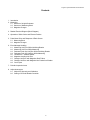
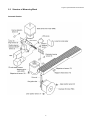
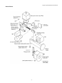
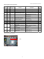
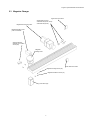
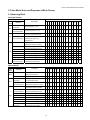
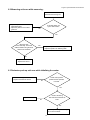
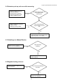
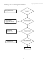
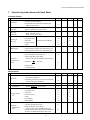
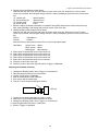
InLight™ Systems Readers
Service Manual
For Models:
Manual Reader ZPA-500
Automatic Reader 200 Unit ZPA-710
Automatic Reader 500 Unit ZPA-700
Version 3 September 2006
© Landauer, Inc. 2006
InLight™ Systems Reader Service Manual
Contents
1. Introduction
2. Measuring
2.1 Structure of InLight Dosimeter
2.2 Structure of Measuring Block
2.3 Magazine Changer
3. Reader Electrical Diagram (Block Diagram)
4. Operation of Slide Carrier and Element Position
5. Pulse Motor Drive and Response of Each Sensor
5.1 Measuring Block
5.2 Magazine Changer
6. Error Message Handling
6.1 Measuring Unit Error While Initializing Reader
6.2 Measuring Unit Error While Measuring
6.3 Dosimeter Push Up Unit Error While Initializing Reader
6.4 Dosimeter Push Up Unit Error While Measuring
6.5 Unload Error – Manual Reader
6.6 Magazine Loading Unit Error
6.7 Changer Unit Error with Magazine Shelf Failure
6.8 Changer Unit Error with Magazine Not Pushed into Reader
6.9 Cover Open
7. Periodic Inspection Items
8. Adjust Instruments
8.1 Adjust LED Intensity and Calibration
8.2 Setting of 2D Code Reader Controller
2
InLight™ Systems Reader Service Manual
1. Introduction
InLight Systems Readers provide readout for InLight Systems dosimeters, and each system includes a reader,
an external PC, and dosimetry software. The InLight software resides on the external PC and provides control
over the setup, analysis, and data recording enabling dosimeter read out and reader quality control. This
service manual covers the InLight Systems manual reader, the 200 capacity automatic reader, and the 500
capacity automatic reader.
InLight Systems are automated dosimetry systems using Landauer’s optically stimulated luminescence (OSL)
technology. Dosimeters measure radiation exposure with aluminum oxide detectors (Al2O3:C) and OSL
technology. The reader stimulates the detector with a light emitting diode (LED) array causing it to luminesce
in proportion to the amount of radiation exposure and the intensity of stimulation light. The luminescence is
detected and measured by the reader’s photomultiplier tube using a high sensitivity photon counting system. A
dose calculation algorithm is then applied to the measurement to determine exposure results.
2. Measuring
2.1 Structure of InLight Dosimeter
InLight dosimeters are built on an assembly of a case component with metal and plastic filters along with a
four-positioned aluminum oxide detector slide component. Both the case and slide are uniquely bar coded with
serial numbers for chain of custody and sensitivity identification.
The InLight dosimeter and the InLight calibration dosimeter are shown below. A maximum of four elements are
located in the slide, and the slide is inserted in the case to shield from exposure by light. The case and slide
bar codes are automatically read in the InLight reader.
Slide
2-D code2D Barcode
Case
Open Window
Calibration dosimeter
Window Type With Filters
3
InLight™ Systems Reader Service Manual
2.2
Structure of Measuring Block
Automatic Readers
4
InLight™ Systems Reader Service Manual
Manual Reader
5
InLight™ Systems Reader Service Manual
Measuring Block Sensor Descriptions
Sensor
RSR
No.
LED
No.
Signal Name
PC No.
1
2
3
4
1
2
3
4
116
115
114
113
2DCR_RDY
2DCR_ERR
Shutter solenoid on/off
Overrun position of carrier
5
5
112
Measurement position of carrier
6
6
111
Origin position of carrier
7
7
110
Lower position of dosimeter
8
8
19
Upper position of dosimeter
9
9
18
Existence of dosimeter
10
11
12
13
10
11
12
13
17
16
15
14
13
14
14
13
12
15
16
15
16
Function
Description
Manual Reader: inside position of
manual loader
Automatic Reader: magazine slot
position
Manual Reader: outside position
of manual loader
12
Automatic Reader: magazine end
11
Magazine head
LED1-16:on PCB (UDP516003A)
LEDs
6
2D code reader is ready.
2D code reader error.
When solenoid is energized, LED is off.
When slide carrier overruns, this is off.
When measuring E1, E2, E3 or E4, this is
on.
When slide carrier stops at the origin
position, this is on.
When the dosimeter stops at the lower
position, this is on.
When the dosimeter stops at the upper
position, this is on.
When checking for dosimeter, this is off if
the dosimeter exists.
When the manual loader is pushed in, this
is off.
When the dosimeter is in measuring
position, this is on.
When the manual loader is pushed out,
this is off.
When the sensor detects end of
magazine, this is on.
When the sensor detects head of the
magazine, this is off.
LED
Active
State
OFF
OFF
ON
OFF
ON
ON
ON
ON
OFF
OFF
ON
OFF
ON
OFF
InLight™ Systems Reader Service Manual
2.3
Magazine Changer
Upper limit micro switch
Magazine shelf moving motor
Shelf position sensors:
Automatic 500 (22-25, 29-34)
Automatic 200 (29-32)
Magazine feeding motor
push-out solenoid
Solenoid ON-OFF
detection micro switch
sensor (26)
Magazine
feeding motor
Lower limit micro switch
Magazine housing sensor (28)
Magazine existence sensor (27)
Door switch (35)
7
InLight™ Systems Reader Service Manual
Magazine Changer Sensor Descriptions
Sensor
RSR No.
LED
No.
21
22
23
24
25
1
2
3
4
5
Judgment of changer
Automatic 500 No. 10 shelf position
Automatic 500 No. 9 shelf position
Automatic 500 No. 8 shelf position
Automatic 500 No. 7 shelf position
26
6
Solenoid detection switch
27
7
Existence of magazine
28
8
29
9
30
10
31
11
Magazine housing sensor
Automatic 200 No. 4 shelf position
Automatic 500 No. 6 shelf position
Automatic 200 No. 3 shelf position
Automatic 500 No. 5 shelf position
Automatic 200 No. 2 shelf position
Automatic 500 No. 4 shelf position
Function
Automatic 200 No. 1 shelf position
32
12
Automatic 500 No. 3 shelf position
33
13
Automatic 500 No. 2 shelf position
34
14
Automatic 500 No. 1 shelf position
35
15
36
16
Automatic 200 cover open
Automatic 500 front door open
Automatic 200 judgment of reader
Automatic 500 judgment of reader
Description
When this shelf of the magazine is shifted to the
position of the first step, this is on.
When the magazine feeding motor is in original
position, this on.
When checking the magazine, if the magazine exists
this is off.
When a magazine is in original position, this is on.
LED
Active
State
ON
ON
OFF
OFF
When this shelf of the magazine is shifted to the
position of the first step, this is on.
When this shelf of the magazine is at the original
position, this is on.
When this shelf of the magazine is shifted to the
position of the first step, this is on.
When this shelf of the magazine is shifted to the
position of the first step, this is on.
When this shelf of the magazine is at the original
position, this is on.
If cover of reader is open, this is on.
If the front door of the changer is open, this is off.
If this LED is on, the reader is manual.
If this LED is off, the reader is automatic.
LED1-16: on PCB (UDP516003A)
8
ON
OFF
OFF
ON
InLight™ Systems Reader Service Manual
3. Reader Electrical Diagram
Power Supply
+5V
Controller
PMT
+5V / +24V
External Unit
+12V
CPU Board
COM
Board
2D Code Reader Camera
I/O for
Reader
PM Driver
PM
PIO Board
Bar Code
Reader
Mechanism Unit
I/O for
Changer
Changer Unit
9
InLight™ Systems Reader Service Manual
4. Operation of Slide Carrier and Element Position
2DC camera
Origin detection LED
Camera for 2D Code Reading
Original Position LED
Measuring position detection LED
PMT
Measuring Position LED
Overrun detection LED
Overrun Detection LED
Original Position
Bar Code Reading
Overrun detecting
phototransistor
2D Code Reading Position
Measuring position detecting
phototransistor
CAL Reading Position
Origin detecting phototransistor
Element existence sensor
Irradiation LED
E1 Measuring Position
E2 Measuring
Position
Secondary
code
reading position
Overrun detection sensor
PMT position
Origin sensor position
E3 Measuring Position
Measuring sensor position
E4 Measuring Position
Overrun Detection Sensor
Measuring Position Sensor
Bar Code Reader
Original Position Sensor
Element Existence Sensor
LED Source
10
InLight™ Systems Reader Service Manual
5. Pulse Motor Drive and Response of Each Sensor
5.1 Measuring Block
Automatic Readers
Main Operation
Pulse
Motor
Direction
Forward magazine
PM1
(clockwise)
Reverse magazine
(counterclockwise)
Push up (clockwise)
Sensor Response (LED)
Description
1=ON
1
2
3
4
5
6
7
8
9
10
11
12
13
14
15
16
Feed magazine by 1 slot
0
0
1
1
0
1
1
0
1
0
0
0
0
1
0
0
Reverse magazine by 1 slot
0
0
1
1
0
1
1
0
1
0
0
0
0
1
1
1
0
0
1
1
0
1
0
1
1
0
0
0
0
1
0
0
0
0
1
1
0
1
1
0
1
0
0
0
0
1
0
0
0
0
1
1
0
1
0
1
1
0
0
0
0
1
0
0
0
0
1
1
0
0
0
1
1
0
0
0
0
1
0
0
Move dosimeter from the magazine
slot to the measurement origin
PM2
0=OFF
Down
Reverse dosimeter from the
(counterclockwise)
measurement origin to the
magazine slot
Dosimeter measurement origin or
Ref-element measuring position
Pull out (clockwise)
2D code reading position (from
dosimeter measurement origin)
PM3
Same above
Ref-light measuring position (CAL)
0
0
1
1
1
0
0
1
1
0
0
0
0
1
0
0
Same above
Element 1 measuring position
0
0
1
1
1
0
0
1
1
0
0
0
0
1
0
0
Same above
Element 2 measuring position
0
0
1
1
1
0
0
1
1
0
0
0
0
1
0
0
Same above
Element 3 measuring position
0
0
1
1
1
0
0
1
1
0
0
0
0
1
0
0
Same above
Element 4 measuring position
0
0
1
1
1
0
0
1
1
0
0
0
0
1
0
0
Reverse
Reverse to the dosimeter
(counterclockwise)
measurement origin position
0
0
1
1
0
1
0
1
1
0
0
0
0
1
0
0
Manual Reader
Main operation
Pulse
Motor
Direction
Load a dosimeter
PM1
PM2
Sensor Response ( LED)
Description
Manually push the dosimeter
loader into the machine
Push out
Dosimeter loader moves out
Push up
Move dosimeter from the loader to
(clockwise)
the measurement origin
Down
Reverse dosimeter from the
(counterclockwise)
measurement origin to the loader
Dosimeter measurement origin or
Ref-element measuring position
PM3
0=OFF
1=ON
1
2
3
4
5
6
7
8
9
10
11
12
13
14
15
16
0
0
1
1
0
1
1
0
1
0
0
0
0
1
0
0
0
0
1
1
0
1
1
0
1
0
0
0
0
0
1
0
0
0
1
1
0
1
0
1
1
0
0
0
0
0
1
0
0
0
1
1
0
1
1
0
1
0
0
0
0
0
1
0
0
0
1
1
0
1
0
1
1
0
0
0
0
0
1
0
0
0
1
1
0
0
0
1
1
0
0
0
0
0
1
0
Pull out
2D code reading position (from
(counterclockwise)
dosimeter measurement origin)
Same above
Ref-light measuring position (CAL)
0
0
1
1
1
0
0
1
1
0
0
0
0
0
1
0
Same above
Element 1 measuring position
0
0
1
1
1
0
0
1
1
0
0
0
0
0
1
0
Same above
Element 2 measuring position
0
0
1
1
1
0
0
1
1
0
0
0
0
0
1
0
Same above
Element 3 measuring position
0
0
1
1
1
0
0
1
1
0
0
0
0
0
1
0
Same above
Element 4 measuring position
0
0
1
1
1
0
0
1
1
0
0
0
0
0
1
0
Reverse
Reverse to the dosimeter
(clockwise)
measurement origin position
0
0
1
1
0
1
0
1
1
0
0
0
0
0
1
0
11
InLight™ Systems Reader Service Manual
5.2
Magazine Changer
Motor
or
Solenoid
Main Operation
Load (clockwise)
M1
Description
Direction
Feed the magazine into the
reader
Unload
Draw back the magazine from
(counterclockwise)
the reader
Original position of magazine
shelf
M2
SOL
Forward (up)
Second stage of the magazine
(clockwise)
shelf
Same above
Third stage of the magazine
shelf
Same above
Fourth stage of magazine shelf
Reverse (down)
Original position of the
(counterclockwise)
magazine shelf
Excitation
Non-excitation
Unloading position of
magazine feeding motor unit
Loading position
Sensor Response (LED)
0=OFF
1=ON
1
2
3
4
5
6
7
8
9
10
11
12
13
14
15
16
0
0
0
0
0
1
0
0
0
0
0
1
0
0
0
0
0
0
0
0
0
1
0
0
0
0
0
1
0
0
0
0
0
0
0
0
0
1
0
0
0
0
0
1
0
0
0
0
0
0
0
0
0
1
0
0
0
0
1
0
0
0
0
0
0
0
0
0
0
1
0
0
0
1
0
0
0
0
0
0
0
0
0
0
0
1
0
0
1
0
0
0
0
0
0
0
0
0
0
0
0
1
0
0
0
0
0
1
0
0
0
0
0
0
0
0
0
1
0
0
0
0
0
1
0
0
0
0
0
0
0
0
0
0
0
0
0
0
0
1
0
0
0
0
6. Error Message Handling
6.1 Measuring unit error while initializing the reader:
・Adjust the play between the main
housing and slide carrier.
No
Test sensors 5 and 6 - verify
LEDs switch on and off.
Yes
・Adhesion of dust in the main housing.
Conduct cleaning.
・Replace the sensor.
12
InLight™ Systems Reader Service Manual
6.2 Measuring unit error while measuring:
Power off.
Dismantle the housing unit.
・Adjust the position of the slide
lock/release plate.
・Adjust the position of the carrier
guide rail.
Is the slide drawn out
by the slide carrier?
No
Yes
Move the slide
carrier manually. Is the load
different while moving the slide
carrier front and back?
Yes
・Adjust the position of the carrier guide rail.
・Adjust the position for attaching PM3.
No
・Replace PM3.
・Replace the sensor.
6.3 Dosimeter push up unit error while initializing the reader:
・Remove sticking dust.
・Replace the defective sensor.
Check if the up/down
position sensor operation
is normal.
No
Yes
Check if the timing
disk and sensor bracket are
loose.
Replace PM2.
No
Yes
Adjust the positioning of the timing
disk or sensor bracket.
13
InLight™ Systems Reader Service Manual
6.4 Dosimeter push up unit error while measuring:
・Adhesion of dust on sensor 9.
・Sensor 9 is defective.
・Up/down sensor is defective.
・Adjust the timing disk for PM2.
・Position of PM2 is incorrect.
Dosimeter does not return to
the magazine after
measurement.
No
Yes
・Shape of dosimeter is incorrect.
・Adhesion of dust.
・Swelling or peeling of label.
Check the dosimeter for
physical defects, burr and
dust.
Yes
No
・Adjust the position of PM2.
・Adjust the position of the magazine guide.
・Adjust the position of the housing.
6.5 Unloading error (Manual Reader)
・Adhesion of dust on sensor 14 or 15.
・Sensor 14 or 15 is defective.
PM1 works while
initializing.
Yes
No
・Check the cable connection of PM1.
・PM1 is defective.
6.6 Magazine loading unit error:
・Check if connection of PM1 is correct.
・PM1 is defective.
PM1 works while initializing
the reader.
No
Yes
・Adhesion of dust on sensor 14.
・Sensor 14 is defective.
14
InLight™ Systems Reader Service Manual
6.7 Changer unit error with magazine shelf failure:
Move the magazine shelf by
the toggle switch to release overrun.
Yes
Check if the magazine shelf
is overrun.
No
・Magazine direction.
・Shape of magazine.
・Inclusion of dust and foreign
materials.
Check if the magazine
shelves are jammed.
No
Yes
・Check the wiring.
・Correct the wiring.
・Replace the sensor.
Check if sensors 29-32
operation is normal.
No
Yes
・Confirm the motor or the
break pack is normal.
No
Check if operation of the
motor (motor for moving
shelves) is normal.
Yes
Replace the PCB.
15
InLight™ Systems Reader Service Manual
6.8 Changer unit error with magazine not pushed into reader:
・Micro switch is defective.
・Adjust the position of the bearing holder.
Test if the microswitch clicks when the magazine
shelf is emptied and the lateral
feed gear is pulled
to front.
No
Yes
・Adjust the position of the lateral feed unit.
・Adjust the position of the bearing holder.
Insert magazines into the
magazine shelf and see if the
above can be tested.
No
Yes
・Replace the solenoid.
・Adjust the position of the solenoid.
Test if the solenoid works.
No
Yes
Replace sensor 6.
6.9
Cover open error:
・Door micro switch is defective.
・Check and correct the wiring.
・Adjust the door position.
Has the error
occurred when the door of the
magazine changer is opened
while the magazine changer
is operating?
No
Yes
Close the door and check the wiring.
16
InLight™ Systems Reader Service Manual
7. Periodic Inspection Items and Check Sheet
Automatic Readers
Inspection Contents
6 Month
・ Fan in the rear of the main unit starts operation
1
Power ON
(No abnormal sound allowed.)
・ Initial operation of the machine should be correctly
made. (No error allowed.)
2
3
Checking
CAL Value
Checking
LED Value
・ Value of Ref-light should be STD±10%.
STD = the standard value of each reader
4
5
each unit
Measurement
Weekly
Daily
○
○
○
○
○
○
○
○
Check
・ Value of LED should be
Weak : 800 counts ±30 %
Strong : 10,000 counts ±30 %
・ PMT filter
Cleaning of
Monthly
○
・ CAL glass surface
(No dust and no dirt allowed)
・ Slide carrier
○
○
○
○
・ Inside the housing
○
・ Shutter
○
○
○
・ Checking measuring operation by PC
○
・ Checking reading operation of bar code reader by PC
○
・ Checking reading operation of 2D code reader by PC
○
・ Zero-point check
○
・ Value of Ref-light should be STD±10%.
○
・ Checking calibration (value setting)
Equipment
6
(Using 10 elements with irradiation of about 200mR)
calibration and
check
Read value
X
A
×100 ≤ 10%
○
Expected value
A : Irradiating value
Manual Reader
Inspection Contents
6 Month
・ Fan in the rear of the main unit starts operation. (No
1
Power ON
abnormal sound allowed.)
・ Initial setting of the main unit of the machine should be
correctly made. (No error allowed.)
2
3
4
Checking CAL value
・ Value of Ref-light should be standard±10%.
Manual
・ Manual measurement should be correctly made by
measurement
Cleaning of each
unit
Equipment
5
calibration and
check
selecting MANUAL on the PC screen.
○
○
○
○
○
○
○
・ Card carrier
○
・ Inside the housing
○
・ Shutter
○
・ Input (ENTRY)
○
・ Output (DUMP)
○
・ Zero-point check
○
・ CAL value: standard value±10%
○
・ Checking calibration (value setting)
The ratio of S-LED/W-LED should be within±10%.
17
Daily
○
・ CAL glass surface
(Using 10 elements with irradiation of about 1R)
Weekly
○
・ PMT filter
Compare the read value of Strong LED and Weak LED.
Monthly
○
○
○
○
○
Check
InLight™ Systems Reader Service Manual
8. Reader Internal Adjustments
8.1 Adjust LED Intensity and Calibration
1. Initial Setting
(CP 3-GND)=(CP2-GND)=11.5V(Max.12V)
(CP 1-GND)=1.5V(Max.12V)
Adjust the VRs V1, V2, V3 so that the initial setting is shown above.
CP3
CP2
CP1
GND
V3
V2
V1
2. To Adjust LED Voltage
Irradiate 5R (137-Cs) on InLight element for adjustment, read 10 times continuously, and adjust V1, V2 and
V3 so that the average of the count of S-LED (high luminous intensity) and W-LED (low luminous intensity) is
in the following range.
In case the count number is small, increase the voltage (V*), and in case the count number is large, decrease
the voltage (V*).
However, V1≒V2.
In this event, the following standard should be satisfied.
(a) S-LED: 50000±5000 counts
(b) W-LED: 4000±500 counts
(Record) V1, V2, V3, S-LED count average, W-LED count average.
3. Reference Measurement
The following state shall occur in the reference measurement.
(1) DARK
The average of 10 times measurement results should be less than 20 count/sec.
In case of NG, light leak is possible. Check, and if the result is still NG, replace the PMT.
(Record) average value.
(2) CAL
The average of 10 times measurement results should be less than 500~3000 count/sec. and the
variation factor should be 5% MAX.
In case of NG, replace the PMT.
(Record) average value, variation factor
(3) LED Luminance Intensity Measurement
The average of 10 times measurement results should satisfy the following standard for S-LED and W-LED.
(a) S-LED : 10000±3000 counts
(b) W-LED : 800±240 counts
In case the count number is small, increase the voltage (V*), and in case the count number is large,
decrease the voltage (V*).
However, V1≒V2.
Check that the test standard “2. Adjusting LED Voltage” is satisfied.
(Record) V1, V2, V3, S-LED count average, W-LED count average.
18
InLight™ Systems Reader Service Manual
4. Linearity Check
Prepare InLight element for adjustment without irradiation (annealed *1), and one each with 10mR,
approximately 150mR, 1R, 10R, 100R and 500R irradiated (137-Cs).
The average of 3 times measurement results should satisfy the following standard.
(a) Average of 1R (standard), 10R, 100R and 500R should be within ±20% for W-LED.
(b) Average of 1R (standard), approximately 150mR and 10mR should be within ±20% for S-LED.
However, deduct the count number with no irradiation from the count number with 10mR.
(Record) Average count with the respective radiation dosage.
*1 For annealing, leave elements under fluorescent light (about 40W) with ultraviolet removed for more than two
hours.
8.2 Setting of 2D Code Reader
Setting 2D Code Reader Controller
Connect the keypad monitor and make setting.
1. Press the center of the cursor key in the center and display [Setting] on the screen.
2. Press B key.
3. Select [Setting parameters] with the cursor key and press the center of the cursor key.
4. Change parameters as shown below.
Select an item with the cursor key and press the center of the cursor key. When the up cursor or down cursor
key is pressed, the setting will change. When the setting is displayed, press the center of the cursor key.
A. Operator modes
(1) Reading mode
: <Trigger>
(2) Number of retries
: False
(3) Double read protection
(4) Read time-out time
: None
(5) Trig. Continuous:
(6) On delay time
(7) OFF delay time
(8) OK output time
B. Communication conditions
(1) Comm. protocol
:
<None>
(2) Comm. speed
:
9600 bps
(3) Data pit length
:
8 bits
(4) Parity
:
None
(5) Stop bit
:
1 bit
(6) Response signal waiting time: 2S
(7) Handshake
:
None
(8) Data format
:
Header: ESC
Terminator: CR
Data number: None
Sum check data: None
Code Identification: False
Final null(00x0)data: Not send
Replay data at read- in error :False
Error correction rate: False
Position around 2D code : False
Reading time: False
Soft. trig. third character : 00
Soft. trig. fourth character : FF
5. When setting parameters is completed, select [Exit] and press the center of the cursor key.
Next, select [Camera parameters] and press the center of the cursor key.
19
InLight™ Systems Reader Service Manual
6. Change camera condition as shown below.
Select an item with the cursor key and press the center of the cursor key. When the up cursor or down
cursor key is pressed, the setting will change. When the setting is displayed, press the center of the cursor
key.
(1) Camera type
: <Double speed>
(2) Synchronous type : <External sync.>
(3) Camera mode
: <Frame mode>
(4) Shutter speed
: 1/120s
7. When the setting of camera parameters is completed, select [Exit] and press the center of the cursor key.
Next, select [Reading Code setting] and press the center of the cursor key.
8. Change Reading Code setting as shown below.
Select an item with the cursor key and press the center of the cursor key. When the up cursor or down
cursor key is pressed, the setting will change. When the setting is displayed, press the center of the cursor
key.
Priority1
: <Data Matrix>
Priority2
: <NONE>
Select the Priority1 and press the center of the cursor key and press again.
Data Matrix
9.
10.
11.
12.
13.
14.
15.
Symbol colon : <Block>
Mirror symbol : <false>
Marking type : <Dot marking>
Select <Exit> and press the center of the cursor key.
Select <Exit> and press the center of the cursor key.
Select <Exit> and press the center of the cursor key.
Select <Exit> and press the center of the cursor key.
Select <OK> and press the center of the cursor key.
Press the center of the cursor key.
Press the center of the cursor key and confirm <Trigger> is displayed.
Adjusting the Contrast of Camera
1.
2.
3.
4.
5.
6.
Change the <Reading mode> from <Trigger> to <Continuous>.
Save the parameter and return to initial mode.
Confirm <Continuous> is displayed.
Start the measurement of the dosimeter.
Error occurs and the reader stops.
Turn the ‘A’ of the camera watching the monitor.
A
Camera
LED unit
7. Confirm the two points changing from <NG> to <OK>.
8. Adjust the ‘A’ to the middle position between two points.
9. Change the <Reading mode> from <Trigger> to <Continuous>
10. Save the parameter and return to initial mode.
11. Confirm <Trigger> is displayed.
20