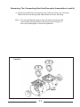
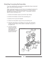
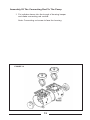
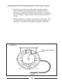
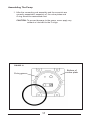
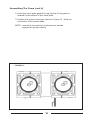
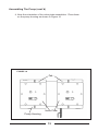
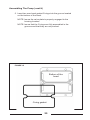
1
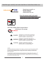
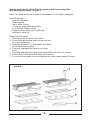
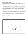
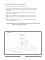
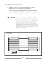
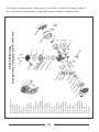
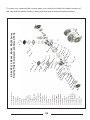
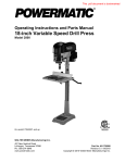
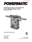
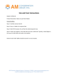
OPERATING
SERVICE
MAINTENANCE
MANUAL
ALL-STAR ROCKING PISTON
COMPRESSOR AND VACUUM PUMP
Registered by one or more of these standards agency
CE
ISO
9001
RoHS
Compliant
Read through carefully and understand these instructions before use.
Contact your supplier or
All-Star Products
Tel 901-755-9613
www.all-star-usa.com
Information
Have the pump model and serial
numbers when ordering parts or when
contacting All-Star or your supplier.
Read the Safety Rules below before
working on the pump.
Safety Rules
Indicates an imminently hazardous
situation which, if not avoided, will
result in death or serious injury.
!
DANGER
!
Indicates a potentially hazardous
WARNING situation, which, if not avoided, could
result in death or serious injury.
!
CAUTION situation, which, if not avoided, may
Indicates a potentially hazardous
result in minor or moderate injury.
NOTE:
This Service Manual is intended for use ONLY by a service center with properly trained
and experienced repair personnel. The instructions and warnings contained herein
presume existing familiarity with the design and function of this type of product and
their components.
The information contained in this manual is subject to change without prior notice. The
manufacturer should be contacted prior performance any maintenance to determine
if any changes have been made to the information contained herein, prior to performing
any service or maintenance work.
1
Connection Diagram
Note: The intake (suction) and the discharge piping should not
be smaller than the connections in the unit. The piping
can be a larger diameter.
If the unit is used in a network arrangement with other
pumps or compressors, the diameter of the piping should
not be less than the total surface area of the total number
of pumps connected in the network.
VACUUM PUMP CONNECTION
Capacitor
Discharge
Connection
Inlet (Suction)
& Filter
COMPRESSOR CONNECTION
Capacitor
Discharge
Connection
Inlet Filter
2
COMMISSIONING
!
DANGER
This pump and compressor is to be used for pumping
non-aggressive gasses (air) containing no more that 22%
oxygen. This unit is not approved for nor should be used
for explosive or toxic gasses.
!
WARNING
RISK OF BURNS - DO NOT TOUCH
The surface temperature of the machine can reach 80 Deg
C (175 Deg F) when operating at full load conditions. Wait
until the unit cools down prior to performing service work.
1.0 The unit must be installed in a well-ventilated, dust-free room. The
maximum ambient if 40 Deg C (104 Deg F). Intake and discharge air
should be piped to limit ambient air temperature as noted above.
The rocking piston pump is designed for continuous duty.
The cooling fins on the unit should remain open to allow free-air circulation
and the unit must be locate at least 150mm (6 inches) away from any
surface. Do not allow hot air to circulate on or about the unit.
STORAGE
If the unit is placed into storage for a period of time greater than one (1)
year, it should be stored in a dust free area subject to a maximum
temperature of 40 Deg C (104 Deg F), and where it will not be subject to
vibration. If stored for longer than one (1) year, the bearings should be
replaced prior to start-up.
2.0 Mechanical Connections
If the unit is to be connected to a network, a flexible hose should be
installed to eliminate mini-vibrations from reverberating in the system piping.
The connections on the unit are either .25” or .375. NPT threads.
For vacuum applications, piping connections to the exhaust orifice can be
made to direct the heated discharge air to an exhaust outlet. This piping
should not be smaller than the connection on the unit. If a smaller
discharge pipe size is used, this can result in reducing the pump speed and
could overload the motor.
If multiple units are installed on a network system, the exhaust pipe must
equal or be greater than the coss-section of the total diameter of all of the
units in the system.
A drain valve at the lowest point of the exhaust line must be installed to
prevent any condensation from draining back into the unit(s).
Mounting of unit
The unit should be mounted on an adequate mounting base using the
rubber foot pads to isolate any vibration being transmitted to the mounting
surface.
3
ELECTRICAL CONNECTION
The power supply must be the same voltage and frequency as listed on
the nameplate. The motor is a single phase, capacitor type and it has one
cable connection. Connect the incoming power two conductors to the motor
terminals and connect the earth (ground) wire to the earth terminal.
The motor must be protected by a motor starter with a thermal overload. A
circuit breaker of adequate capacity, based on the motor nameplate
amperage must be used.
A thermal protector is wound into the motor winding that can be use for
additional temperature protection of the motor.
!
3
DANGER The motor must always be disconnected from the
power supply prior to performing any maintenance
on the unit. The electrical disconnect should have a
lock-out feature to prevent an accidental start-up
while the unit is being serviced.
MAINTENANCE
The points mentioned in this section are based upon the pump being
applied in what can be considered a normal or standard installation. If the
unit is installed or operated in any excessive condition eg, dirty environment, high temperature and so forth, the needs to be maintained frequently.
Cleaning
The external surface of the pump should be cleaned of any debris to allow
for effective cooling of the unit.
Annual Maintenance
The silencer should be dismantled and cleaned or replaced if necessary.
The filter cartridge should be replaced.
The All-Star rocking piston pump has a designed service life of approximately
10,000 hours. Once the pump reaches this point, or approximately two
(2) years, the cylinder head and casing seal needs to be replaced. This
period is merely a suggestion and is dependent upon the duty cycle and
environmental conditions.
10,000 Hour or Two Year Maintenance
In performing this maintenance, it is recommended to perform the following:
a) Replace the connecting rods or piston cups and sleeves
b) Replace the flapper valves
c) Replace the head O-ring head gasket
d) Replace the valve plate O-rings
Required tools for blower maintenance
a) Torque wrench (required for head screws, connecting rod,
flapper valve screws and pipe plugs
b) Allen head wrench with attachments for torque wrench
c) Cross-head attachment for torque wrench
d) Screw driver
d) Soft, clean cloth
4
Servicing the Head, Valve Plate Assembly and Connecting Rod
and Bearing Assembly - Figure 1
Note: The head would only need to be replaced if it is visibly damaged.
Parts Required:
- Head if damaged
- Head gasket
- Valve plate O-ring
- Complete valve plate assembly
or individual flapper valves
- Flapper valve screw (s) if replacing
individual valve (s)
Removing the Head
1. Disconnect the power to the motor
3. Disconnect all airlines and remove the unit
from any enclosure
3. Remove all screws (1) that faster the head
(2) to the pump housing
4. Carefully separate the head from pump
body.
5. Carefully separate the valve plate assemblies (4) from the heads
6. Remove the head gasket O-rings and replace
7. Turn the valve plates over and replace the valve plate gasket O-rings
FIGURE 1
5
Removing Flapper Valves
Note: It is recommended that you replace one flapper valve at a time. This will
help to simplify the repair process and correctly orient the flapper valves in the
valve plate.
1. If you are replacing a flapper valve on the topside of he valve plate (the side
facing the head), remove the flapper valve screw (1). Lift off the valve keeper
strip (2), lift off the strengthen valve (3) and lift off the existing flapper valve (4).
2. Remove any debris from the valve plate with water-free alcohol (soap or
other detergent should not be used due to the potential for corrosion from
the soap
3. Please the valve plate on the compressor housing and orient it as illustrated.
Make sure the O-ring head gasket is towards the cylinder. Note the orientation
of the valve ports.
4. Orient a new flapper valve (4) over Port 1. Observe the location of the end
of the flapper valve
(continued on next page.)
FIGURE 2
Port 2
Port 1
1 2 3 4
6
Removing Flapper Valves (continued)
5. Place a valve restraint (3) over the flapper valve
6. Place a valve keeper strip (4) over the valve restraint, observing that
the restraint’s radium is facing the valve plate and oriented as shown
in Figure 3.
7. Line up the screw holes in all of the valve components and fix the
screw on the valve plate.
8. Make sure the flapper valve is centered over the port of the valve
plate and that all of the other components line up with the flapper
valve.
9. Tighten the flapper valve screw to 11.5”lbs using a torque wrench
with a screw attachment.
CAUTION: Do not over tighten the flapper valve screw or it will
shear off in the valve plate.
FIGURE 3
5
4
3
7
Replacing A Flapper Valve On The Bottom Side Of The Valve Plate
1. To replace a flapper valve on the bottom side of the valve plate (side
facing the pump housing), remove the flapper valve screw (1), lift off
the valve keeper strip (2).
2. Clean any debris with a soft, damp cloth. Turn the pump housing
head upside down and place the valve plate on the pump head and
orient it shown in Figure 4.
3. Orient a flapper valve (3) over Port 2. Observe the location of the
location of the notches at the end of the flapper valve.
4. Place a valve keeper strip (4) over the flapper valve, observing that
the radius of the valve plate, and oriented as shown in Figure 4.
5. Line up the screw holes in all of the valve components and fix them
upon the flapper valve screw by screws.
6. Make sure the flapper valve is centered over the Port and that the
valve keeper strip lines up with the flapper valve.
7. Tighten the flapper valve screw to 12.4”lbs with a torque wrench.
FIGURE 4
Port 1
4
3
Port 2
2
8
1
Servicing Connecting Rod and Eccentric Assemblies
Note: Refer to the Preventative Maintenance and Troubleshooting
guide in this manual to determine whether a compete connecting
rod assembly, or it’s component parts or an eccentric needs to be
serviced.
Components Required
1. Connecting rod assembly, piston cups and sleeves.
2. Valve plate gasket O-rings
3. Head gasket O-rings, if defective
Removing The Connecting Rod and Eccentric Assembly
Note: Only remove one connecting rod assembly at a time.
1. Carefully remove the cooling fan by pulling it straight off the
pump shaft. Do not pull the motor fan blades.
FIGURE 5
Cooling Fans
9
Removing The Connecting Rod And Eccentric Assemblies (cont’d)
2. Turn the motor shaft to align the eccentric setscrew, the
connecting rod screw separately and with the hole of the
housing. See Figure 6 for location of access hole.
FIGURE 6
Eccentric
screw
access
hole
Eccentric
10
Removing The Connecting Rod And Eccentric Assemblies (cont’d)
3. Slide the eccentric bearing assembly straight off the shaft.
FIGURE 7
11
Removing The Connecting Rod And Eccentric Assemblies (cont’d)
4. Slide and rotate the connecting rod, remove it from the housing.
Remove the connecting rod and piston from the housing.
FIGURE 8
12
Removing The Connecting Rod And Eccentric Assemblies (cont’d)
4. Slide and rotate the connecting rod, remove it from the housing.
Remove the connecting rod and piston from the housing.
Note: Do not damage the piston cup (4) when removing the
connecting rod assembly from the pump housing. If
the cup is damaged, it must be replaced.
FIGURE 8
13
Rebuilding Connecting Rod Assemblies
If you are rebuilding the connecting rod assembly using component
parts, follow the procedure below.
When replacing the piston cup (4), be sure to replace the sleeve (1)
at the same time. Please the connecting rod in a fixture before
attempting to remove the retainer screw. If necessary, heat will
help to remove the piston cup.
1. Remove the retainer screw (2) from the cup retainer
2. Remove the retainer (3) from the connecting rod
3. Remove the cup (4) and discard
4. Place t he new piston cup (4) on the connecting rod.
5. Place the new piston cup retainer (3) on the cup connection
making sure the boss of the retainer is seated in the pilot of
the piston rod.
6. Insert the retainer
screw (2) into the
connecting rod (5)
and tighten the
screw with a torque
wrench to 26”lbs.
FIGURE 9
1
2
3
4
5
14
Assembly Of The Connecting Rod To The Pump
1. Put cylinder sleeve into the trough of housing keeper
and make connecting rod vertical.
Note: Connecting rod screw to face the housing.
FIGURE 10
15
Assembly Of The Connecting Rod To The Pump (cont’d)
2. Replace the eccentric onto the shaft and insert bearing
into connecting rod bearing housing. Rotate eccentric
to line up set screw with access hole in bottom of housing.
Rotate main shaft and let shaft flat and eccentric screen hole
line up vertically. Tighten screw to with a torque wrench to
35 “lbs.
3. Rotate shaft with connecting rod moving up and down. The
connecting rod should move freely with out any obstacle or
restriction. Use Allen head wrench to tighten rod screws.
FIGURE 11
Set screw access
hole
16
Assembling The Pump
1. After the connecting rod assembly and the eccentric are
correctly assembled, assembly of the valve plates and
O-ring should be assembled next.
CAUTION: To prevent damage to the pump, never apply any
sealant or lubricant to the O-rings.
FIGURE 12
Bottom of
valve plate
O-ring grove
17
Assembling The Pump (cont’d)
2. Insert the valve plate gasket O-ring into the O-ring groove
located on the bottom of the valve plate.
3. Position the pump housing as shown in Figure 13. Note the
orientation of the power leads.
NOTE: Insure the connecting rod sleeves are seated
against the pump housing.
FIGURE 13
18
Assembling The Pump (cont’d)
4. Note the orientation of the valve plate assemblies. Place them
on the pump housing as shown in Figure 14
FIGURE 14
Tab
Valve Plate
Pump Housing
19
Assembling The Pump (cont’d)
5. Insert two new head gasket O-rings into the groove located
on the bottom of the head.
NOTE: Insure the valve plate is properly engaged to the
housing locators.
NOTE: Insure that the O-rings are fully assembled in the
grooves and that they are not pinched.
FIGURE 15
Bottom of the
head
O-ring gasket
20
Assembling The Pump (cont’d)
6. Place the head on the valve plate assemblies, observing
the position of the air intake and exhaust ports.
NOTE: Make sure the head gasket O-rings are not pinched.
7. Insert the head screws and tighten each screw in the order
as shown in Figure 16, until it is snug. Used a torque wrench
with a screw adapter to tighten each head screw to 31”lb setting.
!
CAUTION To avoid property damage or personal injury,
always rotate the fan by HAND initially, and
prior to connecting the motor to a power supply.
Check for suction at the air inlet port by placing
one finger over the port as you turn the fan.
You should feel a slight suction with each
rotation of the fan. If you don’t feel suction or
if you hear a “thump” as you turn the fan, DO
NOT CONNECT THE UNIT TO YOUR POWER
SOURCE, and review the assembly procedure to
determine the problem.
FIGURE 16
4
5
6
2
8
3
7
1
Capacitor
21
Troubleshooting Guide
Motor Does Not Start
Possible Cause
Low voltage supply
Corrective Action
Insure rated voltage is
applied by changing power
supply.
Bent motor shaft
Worn bearings
Burned out fuses
Replace entire unit
Replace bearings
Check incoming power and
use only “slow blow” fuses
Motor starter thermal protector Check to see if thermal
protector has tripped
Piston jammed
Dismantle cylinder head
and repair
Motor Overheats
High voltage supply
Low voltage supply
Broken fan
Bent motor shaft
Damaged capacitor
Overload condition
High ambient/poor ventilation
Insure rated voltage is
applied by changing power
supply
Same as high voltage
Replace fan
Replace entire unit
Replace capacitor
Reduce pressure/vacuum
to bring motor amps down
to nameplate rating
Insure the motor ambient
does not exceed 40 Deg C
Motor Starter Trips
Starter OL set incorrectly
Verify starter OL is set
correctly.
Check fuse size
Reduce pump load
Clean air filter & element
Low Pressure/Low Flow
Installation Leak
Wrong direction of rotation
Piston joint not working
Defective blade valve
Dirty air filter
Pump undersized for load
Loose head screws
Damaged valves
Worn cup
Damaged gaskets
Debris in valves
Correct any leakage
Change electrical connection
Replace
Replace
Clean and/or replace
Replace with larger unit
Tighten screws
Replace valves
Replace cup
Replace gaskets
Clean and check for valve
damage
Noisy Unit
Damaged valves
Debris in valves
Replace
Clean and check for valve
damage
Replace
Tighten screws
Replace unit
Replace bearings
Replace silencer
Worn cup
Loose head screws
Bent motor shaft
Worn bearings
Silencer
22
001 Cooling Fan Cover
23
035 Silencer
034 Back Cover
033 O-Ring
gube
032 ConnectinT
031 UpperaVlve Flipper
030 Bearing 6203zz
029 Rubber Foot
028 Capacitor
027 Screw M5-8
026 Bracket
025 Bearing 6006zz
024 Bearing 6006zz
asher
023 Spring W
022 Screw M5-15
021 Fixing Clamp
020 Screw
019 Screw
018 Head Cover
017 Valve O-Ring
016 Valve Plate
015 DownaVlve Flapper
014 Valve Fixed Strip
013 Screw M4-5
012 Cylinder O-Ring
011 Cylinder
010 Screw M5-10
009 Round Plate
008 Piston Cup
007 Stator
006 Rotor
005 Housing
004 Piston Rod
003 Eccentric
002 Cooling Fan
020
001
002
021
003
030
004
008
009
010
023
022
011
012
031
015
014
035
019
029
005
016
017
018
028
026
027
024
006
007
025
034
RP-40 & RP-60 Series
Rocking Piston Compressor and Vacuum Pump
To insure you received the correct parts, you need to provide the model number of
the unit and the serial number, along with the part number as shown below.
001 Cooling Fan Cover
24
035 Silencer
034 Back Cover
033 O-Ring
gube
032 ConnectinT
031 UpperaVlve Flipper
030 Bearing 6203zz
029 Rubber Foot
028 Capacitor
027 Screw M5-8
026 Bracket
025 Bearing 6006zz
024 Bearing 6006zz
asher
023 Spring W
022 Screw M5-15
021 Fixing Clamp
020 Screw
019 Screw
018 Head Cover
017 Valve O-Ring
016 Valve Plate
015 DownaVlve Flapper
014 Valve Fixed Strip
013 Screw M4-5
012 Cylinder O-Ring
011 Cylinder
010 Screw M5-10
009 Round Plate
008 Piston Cup
007 Stator
006 Rotor
005 Housing
004 Piston Rod
003 Eccentric
002 Cooling Fan
020
001
002
003
021
030
004
010
009
008
022
023
005
031
015
035
018
019
011
012
014
029
013
016
017
033
026
028
025
032
024
027
006
007
RP-90, RP-120, RP-140, RP-180, RP-200 Series
Rocking Piston Compressor and Vacuum Pump
To insure you received the correct parts, you need to provide the model number of
the unit and the serial number, along with the part numbers as shown below.
All-Star products are high quality engineered and manufactured blowers.
They are designed to meet international standards and have received
approvals and recognition from one or more, of the following.
Registered by one or more of these standards agency
CE
ISO
9001
RoHS
Compliant
LIMITED WARRANTY
All-Star Products warrants all of its products against defects in material and
workmanship for a period of one (1) year from the date the product was
placed in service, within a maximum of eighteen (18) months from the date
of shipment, whichever occurs first. Purchaser is responsible for providing
adequate and approved storage during the eighteen (18) month period.
Not withstanding the foregoing, any equipment or components of the
products not of All-Star Products manufacture and/or specified by the
Purchaser, is sold under only such warranty as the make thereof extends\
to All-Star Products and All-Star Products is able to enforce, but such items
are not warranted by All-Star Products in anyway. All-Star Products is
not responsible for product failures caused by the Purchaser or their
customer misapplying the product, operating the product beyond the
published ratings and values, misuse, field alterations and changes, lack of
proper maintenance or improper storage. Neglect or accidents are also
excluded from this Limited Warranty. This Limited Warranty is effective
provided (1) the purchaser immediately notified All-Star Products in writing
of the alleged defect after it becomes known to the purchaser and (2) no
alterations, repairs or services have been performed by the Purchaser or
third parties on the product without written approval of an officer of All-Star
Products (3) a properly sized air filter has been installed.
This Limited Warranty does not cover misuse, misapplication, abuse,
neglect or other causes of failure beyond the All-Star Products control. The
product should not be disassembled or a repair attempted. Any attempt to
disassemble or repair to correct a problem by the customer or their agent,
will void the Limited warranty. A disassembled unit will not be considered as
a warranted failure under any circumstances.
For more information, visit http://www.all-star-usa.com
All-Star Products Inc
Main Office & National Warehouse
2095 Exeter Rd Ste 80-324 Memphis TN 38138
Tel 800-431-8258 Tel 901-755-9613 Fax 901-758-0816
[email protected]