1
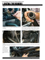
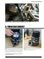
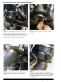
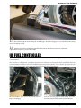
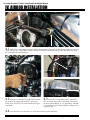
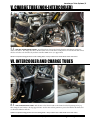
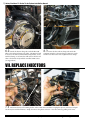
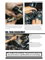
AEROCHARGER TURBO SYSTEM
INSTALLATION MANUAL
HARLEY-DAVIDSON FL-SERIES
Version 1.3
R
INTRODUCTION
Congratulations on your purchase of an
Aerocharger Turbo system for Harley-Davidson
FL-Series motorcycles!
You now own the most powerful, reliable, and technologically
advanced turbo system in the world. With your new turbo system
installed, you will experience substantial performance gains. Our
unique system combines VATN technology with our frictionless,
non-flooded ceramic ball bearing system, which provides zero lag
performance.
This system is proudly made and assembled in the USA by Aerocharger LLC.
CONTENTS
Warnings and Disclaimers.................................................................................. i
I. Install the Headers........................................................................................... 1
II. Turbo and Exhaust......................................................................................... 2
III. Fuel Controller.............................................................................................. 4
IV. Airbox Installation........................................................................................ 5
V. Charge Tube (Non-Intercooled)................................................................... 6
VI. Intercooler and Charge Tubes..................................................................... 6
VII. Replace Injectors......................................................................................... 7
VIII. Final Reassembly........................................................................................ 8
Appendix.............................................................................................................. 9
A. Octane.......................................................................................... 9
B. Engine Upgrades......................................................................... 9
C. Vehicle Maintenance.................................................................. 9
D. Aerocharger Maintenance ........................................................ 9
E. Fuel Controller Fitment............................................................ 10
F. Signal Line Routing Pictorial................................................... 11
i | Harley-Davidson FL-Series Turbo System Installation Manual
WARNINGS AND DISCLAIMERS
Any aftermarket power-adding product can be dangerous to a vehicle if
not used as directed. Aerocharger Turbo Systems are properly engineered,
manufactured with high-quality components, and heavily tested to ensure best
possible reliability. However, many factors that are out of our control, such as
installation errors or misuse, can potentially cause damage. When properly
installed and configured, this system should outlast the life of the vehicle.
Please note the following warnings, carefully follow all instructions, and do not
hesitate to contact an Aerocharger tech if you are unclear about any guidelines
listed here.
INSTALLATION WARNING
If you are uncomfortable performing any installation procedure as
described in this manual, please consult a trained professional at a qualified
performance shop. If you are performing the installation of this system
yourself, we recommend reading the entire manual before beginning the
installation. We also suggest that you review your progress after each section to
ensure that everything has been correctly installed.
MODIFICATION WARNING
This system is designed for use on a stock 2008+ Harley-Davidson
FL-Series motorcycle with an undamaged, well-maintained engine. If your
motorcycle is modified, consult with Aerocharger before proceeding.
Aerocharger is not responsible for ECU tuning and programming,
but will provide assistance when possible.
ENGINE BREAK-IN WARNING
Installing turbo systems on brand-new vehicles is not recommended.
New engines require a specific break-in procedure that does not factor in
extra stress from forced induction. If the vehicle is new or has low miles,
consult the dealership or owner’s manual to determine the proper break-in
procedure before continuing with this installation. Failure to do so can result
in significant engine damage.
Aerocharger Turbo Systems | ii
WARNINGS AND DISCLAIMERS, CONT’D
OCTANE:
For best performance and reliability, always use the recommended
octane for your specific setup. See Appendix B for recommended octane.
Always listen for signs of detonation. IF DETONATION SHOULD
OCCUR, OR YOU ARE UNSURE IF WHAT YOU ARE HEARING IS
DETONATION, DECREASE THROTTLE IMMEDIATELY and consult an
Aerocharger technician. If the system is installed, configured, and operated
correctly, detonation will not be an issue. Please note that inconsistencies on
stock engines and parts are possible on any new vehicle from an OEM.
INTERNATIONAL OCTANE: Fuels are listed in this manual with
the AKI octane rating commonly used at North American gas stations
[(RON+MON)/2]. Fuels that are sold in Europe and other countries generally
use the RON rating system. If you are located outside of North America, be
sure to use the equivalent octane that is available in your region.
IMPORTANT NOTES
NOTE: Read and understand all safety and technical precautions in this
manual before proceeding. Failure to comply with the instructions in this
manual could result in personal injury, property damage, voided warranties,
and inconsistent or poor performance from the turbocharger system. Contact
Aerocharger with any questions or concerns.
DO NOT let any debris (hard or soft) enter air intakes or exhaust ports during
installation of this turbo kit.
DO NOT use any silicone sealants except as directed in this manual. Silicone
sealants can cause Foreign Object Damage to the turbo. THIS WILL VOID
YOUR WARRANTY.
AEROCHARGER WILL NOT BE HELD RESPONSIBLE FOR
DAMAGE TO THE VEHICLE’S POWERTRAIN.
1 | Harley-Davidson FL-Series Turbo System Installation Manual
I. INSTALL THE HEADERS
1.1 Follow the factory service manual procedure to remove the motorcycle’s seat, gas tank, bags, side panels and stock
exhaust.
1.2
Remove the lower header mount bracket for ease of
installation.
(Two 1/4” allen bolts)
1.3
Reuse the c-clamps from the stock headers on the
new Aerocharger header pipes. Replace with new c-clamps
if they are not in good condition - they must sit flat inside
the manifold flange to prevent exhaust leaks.
1.4
Remove the tapered exhaust gaskets and install the flatter gaskets included in the kit. Loosely mount the Aerocharger
header pipes to the engine exhaust manifold.
1.5
Re-attach
the lower header
mount bracket. Use
blue Loctite on the
5/16 18 allen bolts
and torque to factory
spec.
www.AEROCHARGER.com
(913) 829-3400
[email protected]
Aerocharger Turbo Systems | 2
1.6 Loosely mount the turbo support bracket to the chassis at the back of the header.
II. TURBO AND EXHAUST
2.1
Set up the Aerocharger turbo. Fill with the required
amount of turbo oil: 1 bottle for a 53 Series, or 2 bottles for a
66 Series. Screw the fill plug back in, using thread lock fluid
on the threads, and torque to 35 in-lbs. (3/16” allen wrench)
2.2
Install the filter on the compressor housing and
tighten down the hose clamp to secure.
Refer to Appendix D for information about setting and
maintaining the Aerocharger.
www.AEROCHARGER.com
(913) 829-3400
[email protected]
3 | Harley-Davidson FL-Series Turbo System Installation Manual
2.3
Before mounting the turbo, reinstall the bike’s
right-side plastic cover. Place the metal exhaust gasket on
the turbo exhaust flange, then loosely bolt the turbo to the
header using the included hardware. Use the longer bolts on
the bottom to pass through the turbo support bracket.
2.5
Place the retaining collar over the afterpipe, then
attach the afterpipe to the flange on the turbo. Tighten
down.
www.AEROCHARGER.com
2.4
Bolt the afterpipe flange to the turbo through the
heat shield.
2.6
Attach the boost signal line to the fitting on the
Aerocharger controller bonnet, and secure with a small zip
tie. Without pinching the line, gently secure it with a zip tie
to the bag support and run the line up to the center frame.
(See Appendix F.)
(913) 829-3400
[email protected]
Aerocharger Turbo Systems | 4
2.7
Place bolts through the rear mounting tab on the afterpipe. Attach the afterpipe to the stock bracket on the rear bag
mount, and tighten securely.
2.8
With the turbo, headers and afterpipe installed, firmly snug up all bolts and connections. Tighten the
engine exhaust studs first to prevent exhaust leaks
III. FUEL CONTROLLER
With the tank, bags and panels removed, the fuel controller can be installed at this time. See Appendix E for fitment
recommendations.
Fuel controllers are sold separately - most Harley-Davidson owners will want to use their preferred fuel controller with this turbo
system. Installation and features will vary, and additional dyno tuning will be required to set the controller up on the motorcycle.
Contact an Aerocharger tech or a dyno tuning specialist for information and recommendations.
The fuel controller’s oxygen sensor can be installed into this
bung on the afterpipe.
www.AEROCHARGER.com
Secure the o2 sensor plug to the frame with zip ties. Route
the wiring along the frame towards the fuel controller.
(913) 829-3400
[email protected]
5 | Harley-Davidson FL-Series Turbo System Installation Manual
IV. AIRBOX INSTALLATION
4.1
Remove the breather fittings from the cylinders, and install the included spacers. Refit the bolts with blue Loctite and
torque to factory spec. Then snap the crankcase vent tube assembly onto the breather fittings. Run the breather hose along
the center frame toward the swingarm.
INSTALL T-FITTING HERE TO CONNECT
BOOST GAUGE (OPTIONAL)
TO AIRBOX
FROM TURBO
4.2
Using the new throttle body gasket included in the
kit, install the Aerocharger airbox onto the motorcycle’s
throttle body. Use blue Loctite on the threads and torque to
110 inch.lbs.
4.3
Route the boost signal line from the turbo along
the center frame, and attach it to this fitting on the back of
the airbox with a small zip tie. (See Appendix F.) Carefully
secure this line along the frame with zip ties, taking care not
to pinch the line.
4.4 Screw the airbox cover into the recess on the airbox with the provided hardware.
www.AEROCHARGER.com
(913) 829-3400
[email protected]
Aerocharger Turbo Systems | 6
V. CHARGE TUBE (NON-INTERCOOLED)
5.1
FOR NON-INTERCOOLED SYSTEMS: Attach the silicone charge tube directly from the turbocharger compressor
outlet to the airbox. The charge tube’s blow-off valve will be closest to the airbox, facing inward. A reference line will connect
the blow-off valve to the throttle body and fuel controller’s MAP sensor. (See Appendix F)
NOTE: Be careful about clamp placement to avoid scratching finishes. Always use blue Loctite on bolts that do not have lock washers.
VI. INTERCOOLER AND CHARGE TUBES
6.1
FOR INTERCOOLED SYSTEMS: Bolt the intercooler’s front bracket to the frame above the left passenger foot peg.
Then clamp the rear bracket to the bag support frame. Use the inner rubber grommet to protect the finish on the frame, and
use thread-lock fluid on all bolts.
NOTE: Be careful about clamp placement to avoid scratching finishes. Always use blue Loctite on bolts that do not have lock washers.
www.AEROCHARGER.com
(913) 829-3400
[email protected]
7 | Harley-Davidson FL-Series Turbo System Installation Manual
6.2
Attach the silicone charge tube with the Blow-Off
Valve to the airbox and intercooler outlet. The BOV end will
be closest to the airbox, with the BOV facing inward. Secure
with hose clamps. A reference line will connect the blow-off
valve to the throttle body and fuel controller’s MAP sensor.
(See Appendix F)
6.3
Route the other silicone charge tube under the
swingarm. Attach it to the Aerocharger compressor outlet
and the lower intercooler inlet. Tighten the hose clamps.
VII. REPLACE INJECTORS
7.1
Disconnect the injector retaining bracket with a 27mm Torx screwdriver. Unplug the injector connectors, and pull
out the injectors with their harness. Unclip the wires at the plastic connector - never disconnect by pulling on the wires.
www.AEROCHARGER.com
(913) 829-3400
[email protected]
Aerocharger Turbo Systems | 8
7.2
Replace the stock injectors with the larger injectors
included in the kit. When plugging them in, use gasoline
or a very small amount of silicone grease to lubricate the
injector o-rings.
7.3
Reinstall the injector harness and retaining bracket.
Connect the injectors to the fuel controller if required.
Make sure the connection is fully seated and clicks in place.
Install the injector rail at the same time to avoid pinching
the o-rings. Use blue Loctite on the retaining bracket screw.
VIII. FINAL REASSEMBLY
8.1
With the fuel controller
installed, review the entire installation.
Verify that all wiring and lines are cleanly
routed, and that all connections are
secure.
8.2
Follow the factory service
manual procedure to reinstall the gas
tank, seat, bags, side panels, and all other
parts that have been removed during the
installation of this turbo system.
This completes the installation. If required, the motorcycle
may now be taken to a qualified dyno service for tuning.
www.AEROCHARGER.com
(913) 829-3400
[email protected]
9 | Harley-Davidson FL-Series Turbo System Installation Manual
APPENDIX
A. OCTANE
The Aerocharger turbo system for Harley-Davidson motorcycles has been designed to
operate on 91 octane fuel available at any gas station. Higher octane fuel may be required
depending on engine mods.
NOTE: At single-hose gas pumps, the first 1.5 to 2 gallons of fuel out of the line will be the
grade of octane pumped by the previous customer. A mix of lower-grade fuel will reduce the
total octane and possibly cause detonation.
B. ENGINE UPGRADES
C. VEHICLE MAINTENANCE
This Aerocharger system is upwardly expandable,
and is able to accommodate engine upgrades for
increased horsepower output. It is important
to note that some aftermarket engine parts will
not work in harmony with this system. A poor
combination of powertrain variables can reduce
system efficiency and cost the vehicle in overall
horsepower. Consult an Aerocharger technician
for recommendations on components that work
well with Aerocharger-specific applications.
Any aftermarket power-adding product can
accelerate wear on a vehicle. However, when
properly configured, operated, and maintained,
the turbo system should outlast the life of the
vehicle. Do not neglect the normal maintenance
schedule for your vehicle and pay attention to
its tune and performance, and the Aerocharged
motorcycle will easily be capable of thousands of
boosted miles.
D. AEROCHARGER MAINTENANCE
The Aerocharger is a sophisticated and highly efficient variable
vane turbocharger. Unlike conventional turbos, it does not
require oil pumps or lines. The Aerocharger will not need more
maintenance than any other turbo - this graphic contains
information for adjusting the Aerocharger to ensure best
performance.
BOOST SPRINGS
Aerocharger boost springs are used to set the
boost pressure. Every Aerocharger is shipped
with a green 5 PSI spring already installed.
Available springs include:
5 PSI
GREEN
8 PSI
6 PSI
GREEN
BLUE
BLUE
11+ PSI
7 PSI
9 PSI
BLUE
ORANGE
BOOST FITTING
ORANGE
PN # 66335
JAM NUT
BLACK
Shims can be added
to the springs to
increase the boost in
increments of about .5
to . 75 PSI.
R E TA I N I N G C L I P
PN # 66325
PN # 66328
PISTON
PN # 66322
DIAPHRAGM SHIM
PN # 66333
DIAPHRAGM
PN # 66321
CONTROLLER TOP
PN # 66323
AEROCHARGER OIL
Specialized oil for ultra-high rpm machinery.
Only use genuine Aerocharger Turbo Oil.
The wrong oil can lead to bearing failure.
X1
X2
Aerochargers consume oil throughout their use. The
amount of oil consumed is very small, and the oil
level must only be checked once a year or every
30,000 miles. Aerocharger oil never has to be
changed - only added. There is no benefit to
changing the oil unless it has been contaminated
with a foreign substance, such as if the vehicle has
been underwater for a long time.
PN # 66337
CONTROLLER BONNET
SPRING SHIMS
OIL LEVELS
ADD 1 BOTTLE
FOR 53 SERIES
PISTON SHIM
PN # 66342
SPRING SHIMS
PN # 66338
BOOST SPRING
PN # 66341
DUST SHIELD
PN # 66340
ADD 2 BOTTLES
FOR 66 SERIES
Housing
PN # 66326
CONTROL ROD
PN # 66078
NOTE: NEVER attempt to disassemble
the main Aerocharger housings.
The bearing and vane systems
require specialized tools to take it
apart without damaging it. Contact
Aerocharger for all service and
repairs.
www.AEROCHARGER.com
INTEGRATED BOOST CONTROLLER
CHECKING OIL LEVEL
Remove the fill plug and
use a zip tie as a dip stick
to measure the oil level.
HORIZONTAL ORIENTATION
Oil should be added if the
level is lower
1” (2.5 cm)
1/2” (1.3 cm)
than .5” (1.3
cm.)
Oil is full at 1”
height (2.5 cm.)
Use red thread lock fluid on the threads
when replacing the fill plug and tighten
down securely .
VISIT AEROCHARGER.COM
TO SEE A VIDEO TUTORIAL
ABOUT ADJUSTING THE
AEROCHARGER’S BOOST
CONTROLLER TO AFFECT
TURBO RESPONSE
The Integrated boost controller on the Aerocharger is a simple
mechanical actuator where pressure in a chamber pushes against a spring
to move the vanes. It can be easily disassembled to adjust the boost by
changing springs and/or shims. Manual & electronic boost controllers are
compatible with Aerocharger systems, but are not recommended.
(913) 829-3400
[email protected]
Aerocharger Turbo Systems | 10
E. FUEL CONTROLLER FITMENT
It is important to cleanly route all lines for the turbo system and fuel controller. Take care that all lines
are located so they will not pinch, rub, burn or tear. Make sure that the ECM and electrical plugs connect
securely. It is a good idea to dress all excess line with plastic ties to keep them neat and out of the way.
Proper fitment will reduce the risk of wear and damage, and give the install an OEM appearance.
Suggested fitment under the seat for 2008-15 models. The stock electronics tray has been notched out to
fit the Power Commander unit. Several clips have been filed to add space for the ECU bridge connectors.
Secure all loose wires with zip ties.
www.AEROCHARGER.com
The stock wire tray plastic can be notched to pass
the boost signal line through.
(913) 829-3400
[email protected]
11 | Harley-Davidson FL-Series Turbo System Installation Manual
F. SIGNAL LINE ROUTING PICTORIAL
WARNING: Do not pinch any boost or vacuum line. Do not replace vacuum lines with soft rubber lines. Secure all
lines to their fittings with small zip ties. Poor performance or damage can occur when lines are pinched or come loose.
From the Blow-Off Valve, connect one
arm of the vacuum reference line to the
throttle body. Connect the other arm to
the fuel controller’s MAP sensor.
Run the boost signal
line from the turbo’s
controller along the
frame directly to the
fitting on the Air
Plenum.
A T-fitting can be
installed into the boost
signal line to provide
signal for a boost gauge
(optional).
www.AEROCHARGER.com
(913) 829-3400
[email protected]
Visit us online at
www.AEROCHARGER.com for more
technical resources, such as:
• Digital versions of manuals and field
guides
• Detailed video of installations to refer
to during your install
• Up-to-date tips, tricks, and upgrades
HARLEY-DAVIDSON FL-SERIES
By Aerocharger, LLC
402 New Century Parkway
New Century, KS 66031
(913)829-3400
www.AEROCHARGER.com