1
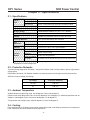
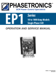
PHASETRONICS
SCR Power Control Specialists
EP1 Series - Power Control
Single Phase SCR
85 to 1000 Amps
OPERATION & SERVICE MANUAL
Phasetronics, Inc.
P.O. Box 17159
13214 - 38th Street North
Clearwater, FL 34622-0159
(813)573-1900 FAX(813)573- 1803
Table of Contents
Chapter 1: Introduction ................................................................................................. 1
1.1 General
1.2 Receiving and Unpacking
1.3 Warning
Chapter 2: Specifications ............................................................................................ 2
2.1 Specifications
2.2 Protective Networks
2.3 Ambient Temperature
2.4 Cooling
Chapter 3: Installation .................................................................................................. 3
3.1 Location
3.2 Initial Unit Inspection
3.3 Warning
3.4 Mounting and Cleaning
3.5 Mounting Enclosure
Chapter 4: Connections ............................................................................................... 4
4.1 Control Connections
4.2 Soft Start (Standard)
4.3 Power Connections
4.4 Control Options
4.5 Current Limit (Option C)
Chapter 5: Start-up ....................................................................................................... 6
5.1 Manual Control
5.2 Automatic Control
5.3 Power-on Soft Start
5.4 Command Signal Change Soft Start (Option S)
5.5 Current Limit (Option C)
5.6 Current Trip (Option T)
Chapter 6: Diagrams .................................................................................................... 7
6.1 Mother Board (85 thru 1000 Amp Units)
6.2 EP1 Series Option Board
6.3 Schematic
6.4 Dimension Configurations
Chapter 7: Troubleshooting ...................................................................................... 12
7.1 Failure Analysis
7.2 SCR Testing Procedure
7.3 Replacing Printed Circuit Boards
7.4 Replacing SCR Device
Chapter 8: Spare Parts............................................................................................... 15
8.1 SCRs
8.2 Main Circuit Board
Chapter 9: Options .................................................................................................... 16
9.1 Soft Start (Option S)
9.2 Current Limit (Option C)
9.3 Current Trip (Option T)
9.4 Line Voltage Regulation (Option R)
EP1 Series
SCR Power Control
Chapter 1 - Introduction
This chapter is a brief introduction to the EP1 Series SCR power controls.
1.1 - General
The EP Series of Phase Angle SCR Power Controls assures smooth proportional output power from 0 to 100%.
This high quality SCR control is offered in a single phase with a variety of options. These options include current
limit, current trip, voltage regulation, soft start on signal change and I2t fusing. The unit is ideally suited for all
resistive and inductive loads. The soft start feature assures a slow rising output voltage to prevent an inrush on
inductive or variable resistance loads. The control input is adjustable to match all standard temperature and
process controllers. The control signal sensitivity is adjustable by gain and offset potentiometers. The unit can
also be controlled from an external manual potentiometer. MOVs(standard) protect the SCRs from transient
voltages. False firing (dv/dt) protection is also standard.
1.2 - Receiving
Upon receipt of this product you should immediately do the following:
•
Inspect the unit for possible shipping damage (if damaged, you should notify the freight carrier and
file a claim within 15 days of receipt)
•
Verify the model number on the unit matches up with your purchase order
1.3 - Warning!
DO NOT SERVICE EQUIPMENT WITH VOLTAGE APPLIED! Unit can be a source
of fatal electrical shocks! To avoid shock hazard, disconnect main power before
working on unit.
-1-
EP1 Series
SCR Power Control
Chapter 2 - Specifications
2.1 - Specifications
External
Inputs
Milliamp Input
4-20 mA Input Impedance - 250 ohms
Analog Input
0-10 Vdc Signal / 0-5 Vdc Signal - 100k ohms input impedance
Manual Control
10k ohm, 2 watt potentiometer, linear taper (customer provided)
Output Current Rating
10 to 1000 Amps
Output Stage
Back to Back configuration
AC Supply Voltage
120/208/240/308/415/480/575 Vac(+10% to -15%, 50/60 Hz) *
Type of Loads
Resistive / Inductive / Lamp
Factory set for initial half-second of operation of power on. Field
adjustable via potentiometer from 0.2 seconds to 30 seconds
A combination of a high-potential gate pulse and a rapid rise time is
used to prevent SCR damage due to di/dt stress
Soft Start
Hard Firing Gate Pulse
Input
Adjustments
Gain
4-20mA, 0-5 Vdc, 0-10 Volts
Offset
50% of gain maximum
Regulation
(Option R)
Protective
Networks
Optional feature to provide average load voltage regulation of plus
or minus 2% for +10% to -10% of gain maximum
Optional Fusing
I2t fuse protects against short-circuit overloads (Option F)
Transient Voltage
Suppressor
SCR Peak Inverse
Voltage (PIV Rating)
Integral MOV (Metal Oxide Varistor) protects against high
potential transient voltage
RC Snubber
RC snubber networks prevent false firing due to dv/dt characteristics
2.5 times line rating (minimum)
Operating range is from 0°C thru 40°C (32°F thru 104°F)
Ambient Temperature
* Dependent on model configuration
2.2 - Protective Networks
Transient Voltage Suppressor (Standard) - Integral MOV (Metal Oxide Varistor) protects against high potential
voltage spikes.
RC Snubber (Standard) - RC Snubber networks are used to prevent false firing due to dv/dt characteristics.
SCR Peak Inverse Voltage (PIV Rating)
Line Voltage
C ontinuous SC R R ating
120 - 4 80
120 0 Vo lts
57 5
150 0 Vo lts
2.3 - Ambient Temperature
Ambient temperature operating range 0 to 40 degrees C (32 to 104 degrees F).
Output current rating decreases by 10% for each 5 degrees C rise (9 degrees F) in ambient temperature over 40
degrees C (104 degrees F) to a maximum of 60 degrees C (140 degrees F).
Transportation and storage range: -30 to 65 degrees C (-30 to 149 degrees F).
2.4 - Cooling
Units rated from 10 to 175 Amps are convection cooled. Units rated at 225 Amps and above are fan cooled and
have a thermostat that will shut down on over temperature.
-2-
EP1 Series
SCR Power Control
Chapter 3 - Installation
3.1 - Location
Proper location of the EP1 Series is necessary to achieve specified performance and normal operation lifetime.
The EP1 Series should always be installed in an area where the following conditions exist:
• Ambient operating temperature:
•
•
•
•
•
Enclosed unit: 0 to 40 degrees C (32 to 104 degrees F) - Type 1 ventilated enclosure
Chassis unit: 0 to 50 degrees C (32 to 122 degrees F)
Protected from rain and moisture
Humidity: 5 to 95% non-condensing
Free from metallic particles, conductive dust and corrosive gas
Free from excessive vibration (below 0.5G)
Open panel units must be mounted in the appropriate type of enclosure. Enclosure size and type must be
suitable to dissipate heat generated by the SCR power control. (NEMA 1 style enclosures can be forced
ventilated to reduce size.) Use the following formulas for sizing non-ventilated enclosures:
ð
Units maximum current (FLA) x 1.5 = watts then
watts / 10 = sq. ft. of exposed area
Non-vented stainless steel
ð
enclosures
( FLA10x 1.5) x 1.5 = sq. ft of exposed area
Non-Vented painted
metal enclosures
3.2 - Initial Unit Inspection
Prior to installing the EP1 Series unit make a complete visual check of all the equipment for possible damage in
shipping and handling. Report damage immediately before attempting to run unit. Check for loose mechanical
assemblies or broken wires which may have occurred during transportation or installation. Loose electrical
connections will increase resistance and cause unit to function improperly. Prior to beginning the installation
verify that the EP1 Series unit is rated for the proper voltage and that the unit is rated for the appropriate load
current.
3.3 - Warning!
Do not service equipment with voltage applied! Unit can be source of fatal electrical
shocks! To avoid shock hazard, remove all sources of power before working on
controller. Warning labels must be attached to terminals, enclosure and control
panel to meet local codes.
3.4 - Mounting and Cleaning
If mounting the EP1 Series unit in an enclosure requires drilling or punching holes in the enclosure, cover the
electrical assembly to prevent metal filings from becoming lodged in areas which can cause clearance reduction
or actually short out electronics. After work is complete, thoroughly clean the area and reinspect the EP1 Series
unit for foreign material. Make sure there is sufficient clearance (six inches) all around the EP1 Series unit for
cooling, wiring and maintenance purposes. To maximize effective air flow and cooling, the unit must be installed
with its heat sink ribs oriented vertically and running parallel to the mounting surface. If unit has a fan, install unit
so the fan blows upward vertically.
In dirty or contaminated atmospheres the unit should be cleaned on a regular basis to insure proper cooling. Do
not use any chemicals to clean the unit; to remove surface dust, use 80 to 100 psi clean dry compressed air only.
A three inch high quality dry paint brush is helpful to loosen up the dust prior to using compressed air on the unit.
-3-
3.5 - Mounting Enclosure
85, 100, 150, 225 and 135 Amp units require a 120 cfm box ventalation fan for NEMA 1 enclosures. 500 Amp and
larger units require a 240 cfm vent fan. See example below.
Box
6″″
6″″
12345678901234567890
12345678901234567890
12345678901234567890
12345678901234567890
12345678901234567890
12345678901234567890
12345678901234567890
12345678901234567890
12345678901234567890
12345678901234567890
12345678901234567890
12345678901234567890
12345678901234567890
12345678901234567890
12345678901234567890
12345678901234567890
12345678901234567890
12345678901234567890
12345678901234567890
12345678901234567890
12345678901234567890
12345678901234567890
12345678901234567890
12345678901234567890
12345678901234567890
12345678901234567890
12345678901234567890
12345678901234567890
12345678901234567890
EP1
Unit
6″″
Note:
6″″
Fan
12
12
12
12
12
12
12
←
Type 1 Box size should be selected incoordination with minimum
field wiring bending space requirements per local and National
Electrical Codes. (NEC Article 373 and table 373-6A)
-4-
Air
Flow
EP1 Series
SCR Power Control
Chapter 4 - Connections
4.1 - Control Connections
4.1.1 Manual Control
1. If manual potentiometer is not used proceed to "Automatic
Control". Manual potentiometer does not have to be connected
for unit to operate.
2. Connect manual potentiometer to TB2-3(wiper), TB2-4(high),and
TB2-6(low) per connection diagram. See figure 1 for connection &
figure 3 for jumper locations.
3. Manual potentiometer is 10K ohm, 2 watts linear taper.
4. If you are using only manual control, proceed to power
connections page 6.
(high)
(wiper)
(low)
Figure 1 - Manual Connections
4.1.2 Automatic Control
1. Connect DC voltage or milliamp input signal to pins 1(positive)
and 2(negative) on TB2. You must select the proper jumper for 420 mA*, 0-5 Vdc or 0-10 Vdc. See location of jumpers on main
logic board diagram section 6.1.
2. If manual and automatic control are both used, consider using an
external auto/manual switch to prevent the manual setting from
overriding the automatic signal. See location of jumpers and pins
figure 3.
Figure 2 - Automatic Connections
0-10 Vdc connection
jumper X3 installed
mA connection
* 4-20
jumper X1 installed (factory setting)
0-5 Vdc connection
jumper X2 installed
Control Board Layout
Figure 3 - TB2 Connections
4.2 - Soft Start (Standard)
The standard soft start ramp adjustment is factory set (P3) for 0.5 seconds. The soft start ramp time can be
increased to a maximum of 30 seconds by adjusting P3 in a clockwise(CW) direction.
Note: Soft start is active only when initial power is applied and a command signal
is present. It has no effect on control signal change. See Option S - Section
9.1 if soft start is required on restart of mA signal or when lockout is released.
-5-
4.3 - Power Connections
1. Connect line 1 and supply side of load to power terminals. See figure 4 below.
2. Connect line 2 (using 18-22 gauge wire) to terminal 6 on TB1(EPCL1000). If option is present,
connect line 2 to terminal 7 of TB2 on option board. See figure 4 and 5 below.
3. Connect line 2 to the return side of load.
Main Logic Board
L2 connection (if no
option card is present)
L1 (Hot)
T1 (To Load)
Figure 4 - Power Connection (no option card)
Option Card
(mounted on main logic board when options are ordered)
L2 Connected to TB2-7
on option card
Figure 5 - Power Connection (with option card)
4.4 - Control Options
O ption
Letter
O ption Nam e
C
C urrent Lim it
This option w ill lim it the output current at a preset level,
adjustable from 0-110% of controller rating. (C u rrent
lim it w ill override control input signal to lim it current
output)
T
C urrent Trip
A djustable from 50-200% for instantan eo us trip if
current exceeds set level. U nit is connected for m anual
reset. C urrent transform er includ ed .
F
F using
This provides an integ ral I2t fu se w hich protects against
short-circuit.
S
Description
P rovides soft start on loss of com m and signal. A llow s
O ptional S oft Start unit to ra m p up on a loss of com m and signal.
4.5 - Current Limit (Option C)
Current limit is typically adjusted for full rated current, therefore appropriate load must be used for this adjustment
to function properly.
1. Apply input control signal to achieve full output.
2. Adjust Current Limit potentiometer (P4 on option board) to desired level. Counter-clockwise(CCW)
rotation of potentiometer will decrease output current level (lower the current limit set point).
-6-
EP1 Series
SCR Power Control
Chapter 5 - Start-up
5.1 Manual Control
The following procedure is used for manual control start-up for the EP1 Series SCR Power Control.
1. If the unit has a milliamp or voltage input and a manual control potentiometer is also used, set the
milliamp or voltage input signal to minimum (0).
2. Slowly rotate manual control potentiometer in a clockwise(CW) direction. Output voltage should
slowly increase with potentiometer rotation.
3. If output voltage appears to be normal, turn the manual control fully counter-clockwise(CCW) (OFF).
Note: If the unit is connected for manual control only and optional current limit is provided, proceed
to current limit start-up procedure (Section 4.5 page 6). If operating under manual control only, you
have completed start-up.
5.2 Automatic Control
The following procedure is used to set up the EP1 Series SCR Power Control for automatic operation.
1. Gain and Offset Adjustments are factory calibrated and shipped to accept 4-20mA DC input signal. If
voltage input signal is used change jumper selector on main logic board. (See page 8)
2. Apply milliamp or voltage input signal and observe output. Unit output should be proportional to
control input signal. If a different control signal is desired, or you want to check calibration, proceed
as follows:
• Apply minimum desired input control signal (example. 4mA).
• Adjust Offset potentiometer (P1) until output voltage is at desired minimum output.
Clockwise(CW) rotation will decrease output (Increase the amount of offset).
• Apply maximum desired input control signal (example 20mA).
• Adjust Gain potentiometer (P2) until output voltage is at desired maximum output.
Clockwise(CW) rotation will increase output. If required repeat these steps to obtain specific
output levels.
• When using the 0-5 or 0-10Vdc automatic signals, optimum performance can be achieved by
re-zeroing the unit using the offset potentiometer P1.
5.3 Power-on Soft Start
When initial power is applied and a command signal is present, the output voltage is ramped to the desired
commmand signal level over an adjustable interval. The interval can be adjusted from 0 to 30 seconds using
potentiometer P3 on the main logic board.
5.4 Command Signal Change Soft Start (Option "S")
Provides soft start on a reapplication of command signal. The unit is set up so that either of these two soft start
modes can be disabled if desired. The unit will ramp up on a reapplication of command signal if this signal is
brought to 0%. The interval can be adjusted from 0-30 seconds using P2 on the option card.
5.5 Current Limit (Option "C")
Adjustable from 0-110% of unit rating. Current limit will override control input signal to limit the output current.
Current transformer included. The level of current limit can be adjusted from 0-125% using P4 on the option card.
5.6 Current Trip (Option "T")
Adjustable from 50-200% for instantaneous trip if current exceeds set level. Unit can be connected for manual or
automatic reset. Current transformer included The level of current trip can be adjusted using P3 on the option card.
-7-
EP1 Series
SCR Power Control
Chapter 6 - Diagrams
6.1 - Main Logic Board for EP1 Series (85 thru 1000 Amp Units)
PCL1002
Note: 380, 575 volt units are not dual connectable.
415 volts is dual connectable (208/415).
-8-
6.2 - EP1 Series Option Board
PCM1603
Note:
All Options are shown here (P1, P2, P3 & P4). Individual configurations may be
different depending on the type of options purchased.
-9-
6.3 - Schematic
- 10 -
6.4 - Dimension Configurations
E P 1 - xx
Amp
A
B
C*
H
W
D
E P 1 - xx10(F )
10
5.53
5.281
0.221
6
5 .75
4.04
E P 1 - xx25(F )
25
5.53
5.281
0.221
6
5 .75
4.04
E P 1 - xx50(F )
50
8.25
6.37
0.28
8.75
7
4.63
E P 1 - xx85(F )
85
9.5
9
0.31
11 .5
9 .88
5.73
E P 1 - xx100(F )
100
9.5
9
0.31
11 .5
9 .88
5.73
E P 1 - xx150(F )
150
8
8
0.31
11 .5
11
8.38
E P 1 - xx225(F )
225
8
8
0.31
12.3
11
8.38
E P 1 - xx350(F )
350
8
8
0.31
12.3
11
8.38
E P 1 - xx500(F )
500
19.37
9.25
0.44
21
11
10
E P 1 - xx650(F )
650
E P 1 - xx800(F )
800
E P 1 - xx1000(F )
1000
xx =
C all F actory
* C = Mounting Hole Diameter
(F) = Unit may include optional fuse
Dimensions subject to change
12 = 120 Volts
20 = 208 Volts
24 = 240 Volts
38 = 380 Volts
41 = 415 Volts
48 = 480 Volts
- 11 -
EP1 Series
SCR Power Control
Chapter 7 - Troubleshooting
7.3 - SCR Testing Procedure
Remove line power from the unit and lock out! Disconnect load and line leads!
Remove line power from the unit and lock out. Disconnect the load and line leads. Disconnect SCR
connections to the main circuit board. Note the type of color coding of the wires going to the SCR plug.
Phasetronics uses two possible configurations. The first configuration consists of 4 wires color coded
black, yellow, grey and white. The second configuration consists of 4 wires color coded red, white, red,
white. The testing procedure for SCRs is comprised of two separate tests.
The first procedure tests the anode to cathode integrity of the SCR by performing the following ohm checks:
+ Lead
- Lead
G ood
C onsult Factory
L1 L ug
T 1 Lug
G re ater than 10 k oh m
Less than 10 k ohm
The second procedure tests the gate to cathode integrity of the SCR. Place the leads of an ohm meter into
the receptacle that was unplugged from the main circuit board. Ohm the pair of wires on one end of the plug
(black/yellow or grey/white). Then ohm the pair of wires on the other end of the plug (black/yellow or grey/
white). The chart below indicates good verses bad readings.
F or w ire that is color coded black, yellow, gray an d w hite
+ L ea d
- L e ad
G oo d
Bad
G ra y
W hite
B e tw e e n 5 a n d 1 0 0 o h m s
Le ss th an 5 o r g re a te r tha n
1 0 0 oh m s
G ra y
W hite
B e tw e e n 5 a n d 1 0 0 o h m s
Le ss th an 5 o r g re a te r tha n
1 0 0 oh m s
For w ire that is color cod ed red, w hite, red and w hite
+ L ea d
- L e ad
G oo d
Bad
Red
W hite
B e tw e e n 5 a n d 1 0 0 o h m s
Le ss th an 5 o r g re a te r tha n
1 0 0 oh m s
Red
W hite
B e tw e e n 5 a n d 1 0 0 o h m s
Le ss th an 5 o r g re a te r tha n
1 0 0 oh m s
Note: If any of the above readings are out of specification, replace the faulty SCR.
7.4 - Replacing Printed Circuit Boards
The printed circuit boards are not intended to be field repaired. If the board is faulty, the entire board should be
replaced using the following procedure: (Important ! Use ESD Precautions any time you replace circuit boards)
1. Remove power from the unit and lock out.
2. Remove plug and tag plug with connector number.
3. Remove control wires from terminals and tag wires with terminal numbers.
4. Note the settings of all potentiometers and jumpers (if applicable).
5. Remove mounting screws.
6. Remove old printed circuit board.
7. Mount new printed circuit board.
- 12 -
8. Install mounting screws.
9. Set the potentiometers and jumpers on the new board to the same positions as on the old board
(if applicable).
10. Install control wires in terminals matching tagged numbers.
11. Install plug matching tagged numbers.
7.5 - Replacing SCR Device
Three types of SCRs are used in Phasetronics EP1 Series depending on the current rating of the SCRs. Stud
and isolated SCRs are used in smaller units and "hockey puck" type SCRs are used in larger units.
7.4.1 - Changing an Isolated SCR
1. Remove both line and control power from unit, tag and lock out.
Warning!
Failure to remove both line and control power before starting this procedure
may cause personal injury or death.
2. Label location of wires connected to SCR.
3. Remove mounting screws, lugs and associated wiring from existing SCR.
4. Make sure the surface to which the power module mounts is clean and free from dirt, nicks, and
scratches.
5. Apply thermal grease uniformly along the length of the power module. Spread the grease thinly (3 mil
thick) to cover completely the base of the power module and minimize air pockets. Grease must be
free of contamination.
6. Replace screws and tighten down firmly.
7. Reconnect all busbars, lugs and wires. Check to make sure gate and cathode are wired correctly.
Main Circuit
Board
Destination
Pin 1
Load Gate
Pin 2
Load Cathode (Output Load Lug)
Pin 5
Line Gate
Pin 6
Line Cathode (Input Line Lug)
8. After verifying that all wiring is correctly connected, apply power and test.
7.4.1 - Changing an Isolated SCR
1. Remove both line and control power from unit, tag, and lock out.
Warning!
Failure to remove both line and control power before starting this procedure
may cause personal injury or death.
2. Phasetronics uses two type of clamps with gauges for reading the amount of torque on the device.
The first type of torque gauge uses a spin washer. When the proper torque is applied, the washer will
be free to spin. The second type of torque gauge uses a step indicator on the end of the lever.
Before proceeding, note the type of clamp used and, if the clamp has a step indicator, document the
position of the indicator before removing the clamp to facilitate proper torquing of the new SCR
device.
- 13 -
3. Label location of wires connected to SCR.
4. Remove any lugs, MOVs, snubbers, printed circuit boards and associated wiring that may get in the
way of reaching the faulty SCR. Document the location and wiring of all parts before removing them
to facilitate the re-installation of the devices later.
5. Document the position of the indicator on the SCR clamp. Then remove top clamp holding SCR
stack together. Remove the top heatsink.
6. Remove faulty SCR device noting the direction the SCR is oriented. The new SCR puck must be
inserted in the same direction.
7. Make sure the SCR mounting surface, tools and hands are clean and free from dirt, nicks, and
scratches. Do not sand or scrape SCR mounting surface. If necessary super fine Scotch Brite pad
can be used to clean the heatsink before installing the new SCR.
8. Apply a thin (3 mil thick) layer of thermal grease uniformly along both sides of the SCR. Spread the
grease to cover the entire surface of both sides of the SCR in a manner that minimizes air pockets.
The grease must be free of contamination.
9. Locate the centering pin in the bottom of the heatsink and center it in the SCR hole making sure that
the SCR is pointed in the same direction as the SCR which was removed in step 6. Locate the
centering pin in the top heatsink and center it in the SCR hole. Hand tighten the clamps evenly so
that the same number of threads appear at both ends of the U-clamp. Tighten the clamp nuts 1/4
turn at a time alternating sides of the U-clamp until the correct torque is reached. Check the gauge or
spin washer every time the clamp nuts are tightened 1/4 turn to ensure that the SCR is not over
torqued. The torque gauge reading should be similar to the initial reading taken in step 2. If the
clamp uses the spin washer type of gauge, verify that the washer spins freely after torquing down the
clamp. Once proper torque is reached make sure that the SCR pucks are securely held between the
heatsinks.
10. Replace any lugs, MOVs, snubbers, printed circuit boards and associated wiring that was removed
in step 4.
11. After verifying that all wiring is correctly connected, apply power and test unit.
- 14 -
EP1 Series
SCR Power Control
Chapter 8 - Spare Parts
SCR Devices
U nit R ating
(A m ps)
120-480 Vo lts
P hasetro nics Part #
575 Volts
P hasetronics Part #
20
25 -0040-1200S D
25-004 0-1500S D
40
25 -0055-1200S D
25-0050-15 00S D
75
25 -0090-1200S D
25-0090-15 00S D
110
25-0940-1200
25-0940-1500
140
25-0940-1200
25-0940-1500
175
25-0940-1200
25-0940-1500
225
25-0940-1200
25-0940-1500
300
25-0940-1200
25-0940-1500
400
25-0940-1200
25-0940-1500
500
25-2170-1200
25-2170-1500
600
25-2170-1200
25-2170-1500
MOV Devices
U nit
C urrent
R ating
Voltage
Phasetronics
Part #
Voltage
Phasetronics
Part Num ber
1 20, 2 08, 2 40
50-040 -0250
120
P T R 14 00-1 20
2 77
50-040 -0510
208
P T R 14 00-2 08
3 80, 4 16, 4 80
50-040 -0510
240
P T R 14 00-2 40
5 75
50-080 -0600
277
P T R 14 00-2 77
1 20, 2 08, 2 40
50-130 -0250
380
P T R 14 00-3 80
2 77
50-190 -0510
416
P T R 14 00-4 16
3 80, 4 16, 4 80
50-190 -0510
480
P T R 14 00-4 80
5 75
50-250 -0660
575
P T R 14 00-5 75
20 - 75
110 - 600
SCR Trigger
I2t Fuse Devices
Unit Rating
(Am ps)
Fuse
Rating
20
30
52-0030-0600
40
50
52-0050-0600
75
80
52-0080-0600
110
125
52-0150-0600
140
150
52-0150-0600
175
200
52-0200-0600
225
250
52-0250-0600
300
350
52-0350-0600
400
450
52-0450-0600
500
600
52-0600-0600
600
800
52-0800-0600
Option Board
Phasetronics
Part Num ber
- 15 -
O ption
Letter
Phasetronics
Part Num ber
B
P C M 12 00-B
C
P C M 12 00-C
D
P C M 12 00 -D
E
P C M 12 00 -E
T
P C M 12 00 -T
V
P C M 12 00 -V
EP1 Series
SCR Power Control
Chapter 9 - Options
The following options are available on the EP1 Series but must be specified when ordering. When options are
ordered a separate option card is mounted on top of the main logic board.
9.1 Soft Start (Option "S")
Provides soft start on a signal change or when lockout is released. This will help protect fuses. The unit is set up
so that either of these two soft start modes can be disabled by removing X1 & X2 on the option card. See figure
6 below or Option board page 9. The unit will ramp up on a signal change if the command signal drops to 0%.
9.2 Current Limit (Option "C")
Provides flexibility for changing loads and helps protect the unit. Adjustable from 10-110% of unit rating. Current
limit will override control input signal to limit the output current. Current transformer included. To disable remove
X1 & X3 on option card. See figure 6 below or Option board page 9.
9.3 Current Trip (Option "T")
Used as a protective measure. This option will shut down the unit when the current exceeds an adjusted preset
level. Adjustable from 75-200% for instantaneous trip if current exceeds set level. Unit can be connected for
manual reset. Current transformer included. To disable remove X4. See figure 6 below or Option board page 9.
9.4 Line Voltage Regulation (Option "R")
Provides more accurate linearity. This option allows the unit to regulate load voltage with a varying line voltage.
The amount of control can be adjusted using P1 on the control board. Will maintain output within 2% with a +/10% line variation.
Option Card (mounted on top of main logic board)
Note: The number of potentiometers on the
option card will vary depending on the
options ordered.
Figure 6 - Option setting locations
- 16 -
Warranty Policy
Phasetronics warrants its products to be free from defects in material and/or workmanship for a period of one
year from date of installation, to a maximum of 18 months from the date of shipment as indicated by the unit’s
date code. The Company reserves the right to repair or replace any malfunctioning units under warranty at their
option. All warranty repairs must be performed by the Company factory or on site by a factory authorized service
firms or personnel approved by the Company.
Solid state controls have different operation characteristics from those of electro-mechanical equipment. Because
of these differences and the wide variety of applications for solid state controls, each application designer must
verify that the solid state equipment is acceptable for his application. In no event will Phasetronics be responsible
or liable for indirect or consequential damages resulting from the use or application of this equipment. The
diagrams and illustrations in this document are included solely for illustrative purposes. Because of the number
of different applications, Phasetronics can not be responsible or liable for actual use based on the examples or
diagrams.
Glossary
The terms that follow relate to
different aspects of Power Controls
offered by Phasetronics. These
terms may not apply to products
offered by other manufacturers.
Breakdown Voltage - Maximum
Collector - One of the hig current
voltage a semiconductor can
support on its nonconducting
direction.
terminals of a transistor (the other
terminal is the emitter).
Bridge - Combination of discrete
Acceleration Time - The time
required for a motor to go from initial
speed to final speed.
Alternating Current AC - A
periodic current, the average of
which over a period is zero and
reverses at regularly recurring
intervals of time and which has
alternatively positive and negative
values.
Ambient Temperature - The
temperature of the air surrounding
an electrical device. If the device
os enclosed, the temperature of the
air inside the enclosure.
Anode - The positive power
terminal of an SCR or Diode.
Assemblies - Combination of
discrete power devices on heat
sinks connected in various circuit
configurations.
Average Current - Current
integrated over a full cycle.
Base - Control terminal of a
transistor.
Blocking Voltage - Ability of a
semiconductor to withstand a
specific voltage stress without
conducting current.
power devices on heat sinks,
generally in circuit configurations to
change AC current to DC current.
Burst Fire - Term used on zerovoltage swithching when SCRs are
turned on for a specified number AC
current to DC current.
CFM (Cubic Feet per
Minute) - Amount of air being
moved. (CFM = LFM x crosssectional area of heat sink)
Case Temperature - Temperature
of package measured at a specific
location. Indirect method for determining junction temperature. For stud
devices, proper thermocouple location is center of any hex flat; for disc
devices, mount thermocouple on
rim (radial edge) of pole face.
Cathode - One of two high current
terminals of rectifier or SCR the
other terminal is the anode. In the
electronic symbol for a rectifier or
SCR, an arrow points toward the
cathode.
Circuit Breaker - An electronic
switching device capable of making,
carrying and breaking currents
under normal circuit conditions and
also, making, carrying for a specified
time and breaking currents under
specified abnormal circuit conditions
such as those of short-circuit.
Contactor - A device, either
electromechanical or solid-state
used to control electric circuits by
closing a physical or electrical path
to allow current.
Combination Starter - A piece
of equipment which incorporates a
motor starter and means for manually
or automatically disconnecting power
to the motor starter.
Conduction Angle - Number of
electrical degrees that current flows.
A full cycle of AC voltage or current
is 360 electrical degrees.
Current Limit - A circuit that
limits the maximum AC current to
the load.
Current Regulation - Circuit
that senses load (output) current
and automatically readjusts the
firing angle of the SCRs to maintain
constant load (output) current with
no control input charge.
DC Regulation - Feedback
supplied from load through dropping
resistor for regulation.
Overload Protection - (Class 10)
A relay’s maximum trip time of 10
seconds at 600% of full load amps.
Overload Protection - Class 20)
A relay’s maximum trip time of 20
seconds at 600% of full load amps.
Diode - See Recitifier
Dry Contact - Contacts of an
electro-mechanical device that will
handle currents of .5mA to 50mA or
a contact closure with no external
voltage applied.
Duty Cycle - Ratio of operating
GPM - Gallons per minute. Water
time to total operating plus nonoperating time.
flow rate trough liquid cooked heat
sink.
dv/dt - Critical rate of rise of off-
Gate - Control terminal of an SCR.
state voltage. The minimum value
of the rate of rise of voltage which
will cause switching from the offstate to the on-state.
Parameter - A value, condition or
Half Control - An arrangement
of rectifiers and SCRs that control
only half the cycle in AC circuits.
One SCR, one Diode.
Emitter - One of high current
terminals of a transistor (the other
terminal is the collector)
Firing Circuit - Electronic
assembly to control the firing pulse
to turn on the power SCR.
Flag Lead - Term used to
describe top terminal on some stud
mount devices. Terminal is a rigid,
metal, flag-shaped connection.
Forward Direction - The
direction of current flow in a
semiconductor.
Forward Polarity - See Standard
Polarity
Free Wheeling Rectifier - (Diode)
Rectifier that is used to bypass the
current due to the stored energy in
the inductance.
Full Control - Circuit utilizing all
SCRs for controlling both half-cycles
in an AC circuit.
I Squared t - This is a measure
of a maximum forward nonrecurring
over current capability for a very
short pulse duration. The value is
valid only for the pulse duration
specified. I = the RMS amperes and
t is the pulse duration in seconds.
I 2 t is necessary for fuse
coordination.
Junction - A transition region
between the positive and negative
layers of a semiconductor.
LFM - Linear feet per minute. Rate
of air flow moving across a cooling
surface.
Leakage Current - The small
currents which get through or
around the blocking characteristics
of a semiconductor device,
capacitor or insulator.
Line Voltage Regulation Control circuit responding to keep
output voltage constant with line
voltage changes.
load circuit from excessive currents.
Gain - Adjustments used to adjust
maximum output of a Power Control
for a specified input. Input from a
temperature controller.
characteristic that is a measurable
property of a device. It may be
electrical, mechanical or thermal
and can be expressed for a given
set of operational and environmental
conditions.
Phase Control Firing - SCR
turned on proportional from 0 to 180
degrees conduction for 0 to 100%
output voltage.
Ramp Time - The time for the
power control to gradually increase
(from the initiation of control signal)
to full output voltage.
Repetitive Forward Blocking
Voltage - The maximum
instantaneous value of the forward
voltage which occurs across the
SCR including all repetitive
voltages.
Repetitive Peak Reverse
Voltage of a Reverse Blocking
SCR - The maximum instantaneous
value of any non-repetitive transient
reverse voltage which occurs across
an SCR.
RMS - Abbreviation stands for rootLockout - Fast shutdown that acts
Fuse - Device which protects the
Offset - Adjustment used to adjust
the minimum input required to start
to have output. The input is from a
temperature controller.
at extremely high speed to sense
high currents and to remove the
SCR gate signal. Load voltage and
currents are removed in less than
10 milliseconds once the set current
is reached. Unit will not restart until
reset.
mean-square and refers to the
effective value of voltage and
current.
Rating - The ultimate or limiting
condition stated for a given device
parameter (either maximum or
minimum) beyond which the device
will not operate properly and/or is
not guaranteed by the manufacturer.
Rectifier - A two-terminal device
where current can flow only on in
the direction of anode to cathode.
Low current rectifiers are frequently
called diodes.
Reverse Direction - Describes
the direction on which a
semiconductor is nonconducting.
Thermal Impedance (Resistance) - The resistance to heat flow
through a material or from one material to another. The unit is degrees C per watt which means the
centigrade degrees of temperature
rise of the material per each watt of
power dissipated at the source.
Thyristor - One of three primary
SCR (Silicon Controlled
Rectifier) - Principle member of
the thyistor family. Is basically a
rectifier with a control feature added.
This three-terminal device (anode,
cathode and gate) is a controllable
on-off switch.
Set Back - The voltage level in a
precipitator control which is less
than the voltage level of the last
spark or arc occurrence.
groups of solid state power devices
(rectifiers, transistors and
thyristors). Principle members of
the thyristor family include SCR,
triac, GTO etc.
Time Base - Reoccurring period
of time that determines the amount
of power delivered to the load of a
zero voltage proportional control.
voltage firing.
Transient (Surge) Suppressor
- An electrical device used to absorb
the energy of extraneous high peaks
of voltage of current. Used to
protect semiconductors from
ruinous overloads.
Soft Start - The time from the
application of line voltage until full
output voltage. This also includes
ramp time.
Solid State - An electrical device
or circuit using semiconductor
devices. (Uses no tubes, rotaries,
m-g sets, thyratrons, ignitions and
vacuum tubes are replaced by
semiconductors.
Spike - An unintended flow of
electrical energy of short duration.
Graphically displayed on a scope as
a very high voltage or current having
a very short duration (usually in the
microsecond range).
that senses load (output) voltages
and automatically readjusts the
firing angle of the SCRs ti maintain
constant load (output) voltage with
no input control change.
Zero Voltage Firing - SCR
gate turned on at zero crossover of
the line current.
a. Time proportional - SCR turned
on for a specific time for a specified
period of time and off for the
remainder of that period.
b. Distributed Cycle - SCR turned
on equal amount of time within the
time base period.
Time Proportional - See zero
Surge Current - The peak value
of a single half wave (ie. 180
degrees of a sine wave), current
impulse at 60Hz. This rating is nonrepetitive and may occur 100 times
within the life of the device.
Voltage Regulation - Circuit
Transient Voltages - Extraneous spikes of high voltage which
appear across a device due to
switching, commutation, interruptions in associated circuitry or by
natural forces such as lightening.
Transients are of very short duration usually in the microsecond
range.
Transistor - Three terminal
(base, collector, emitter) device
used primarily for switching and
amplification.
2 - Leg Control - Three phase
electronics controlling a zero
voltage firing circuit controlling
SCRs in two phases and the third
phase is not controlled.