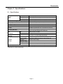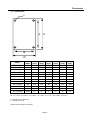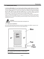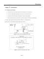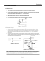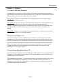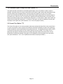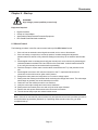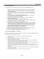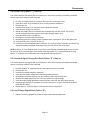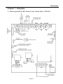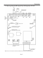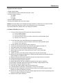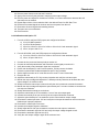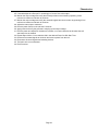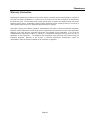
1
PHASETRONI CS TM SCRPowerCont r olSpeci al i st s E P 1 S e r i e s 1 0t o1 0 0 0A mpMo d e l s S i n g l eP h a s eS C R OPERATI ONANDSERVI CEMANUAL MANUAL-EP1 1 101000REV1 REV04/ 26/ 1 3 Phasetronics Table of Contents Chapter 1 - Introduction .................................................................................................................................. 3 1.1 General ............................................................................................................................................... 3 1.2 Receiving and Unpacking .................................................................................................................. 3 Chapter 2 - Specifications ............................................................................................................................... 4 2.1 Specification ....................................................................................................................................... 4 2.2 Dimensions ......................................................................................................................................... 5 2.3 Protective Networks ........................................................................................................................... 6 2.4 Ambient Temperature ........................................................................................................................ 6 2.5 Cooling ............................................................................................................................................... 6 Chapter 3 - Installation .................................................................................................................................... 7 3.1 Location .............................................................................................................................................. 7 3.2 Initial Unt Inspection ........................................................................................................................... 7 3.3 Mounting and Cleaning ...................................................................................................................... 8 3.4 Enclosure Ventilation ......................................................................................................................... 8 Chapter 4 - Connections .................................................................................................................................. 9 4.1 Power Connections ............................................................................................................................ 9 4.2 Control Connections ......................................................................................................................... 10 Chapter 5 - Options ........................................................................................................................................ 11 5.1 Power-on Soft Start (Standard) ........................................................................................................ 11 5.2 Current Limit (Option “C”) ................................................................................................................. 11 5.3 Load Voltage Regulation (Option “R”) .............................................................................................. 11 5.4 Command Signal Change Soft Start (Option “S”) ............................................................................ 12 5.5 Current Trip Option (Option “T”) ....................................................................................................... 12 Chapter 6 - Start-Up ....................................................................................................................................... 13 6.1 Manual Control ................................................................................................................................. 13 6.2 Automatic Control ............................................................................................................................. 14 6.3 Current Limit (Option “C”) Start-up ................................................................................................... 14 6.4 Current Trip (Option “T”) Start-up..................................................................................................... 15 6.5 Command Signal Change Soft Start (Option “S”) Start-up .............................................................. 15 6.6 Load Voltage Regulartions (Option “R”) ........................................................................................... 15 Chapter 7 - Diagrams ..................................................................................................................................... 16 7.1 Main Logic Board for EP1 Series (10 thru 50 Amp Units) - EPCL1001 ........................................... 16 7.2 Main Logic Board for EP1 Series (85 thru 1000 Amp Units) - PCL1002 ......................................... 17 7.3 EP1 Series Option Board (10 thru 50 Amp Units) – PCM1600 ....................................................... 18 7.4 EP1 Series Option Board (85 thru 1000 Amp Units) – PCM1603 ................................................... 19 Chapter 8 - Troubleshooting ......................................................................................................................... 20 8.1 SCR Testing Procedures ................................................................................................................. 20 8.2 Replacing Printed Circuit Boards ..................................................................................................... 21 8.3 Replacing SCR Devices ................................................................................................................... 21 8.4 Calibration Procedures ..................................................................................................................... 21 WARRANTY INFORMATION .......................................................................................................................... 25 Page 2 Phasetronics Chapter 1 - Introduction 1.1 General The EP1 series of power controls is a single phase control available in 120 thru 575vac with current ratings from 10 to 1000A. It provides smooth, phase angle control of back to back SCRs for 0-100% output power control. It comes standard with a selection of 3 automatic and one manual control signal inputs. The integral offset and gain adjustments allow tailoring of the output power with respect to the control signal input. Optional features such as Fusing, Current Limit, Current Trip and Control Signal Soft Start are also available. The SCRs are protected by MOV and dv/dt networks as standard. The EP1 series is well suited for a variety of loads including inductive, resistive and high inrush. 1.2 – Receiving and unpacking Upon receipt of this product you should immediately do the following: • Inspect the unit for possible shipping damage (if damaged, you should notify the freight carrier and file a claim immediately) • Verify the model number on the unit matches your purchase order Warning DO NOT SERVICE EQUIPMENT WITH VOLTAGE APPLIED! Unit can be a source of fatal electrical shocks! To avoid shock hazard, disconnect all power sources before working on unit. Page 3 Phasetronics Chapter 2 - Specifications 2.1 – Specifications External Inputs Milliamp Input 4-20 mA Input Impedance - 250 ohms Analog Input 0-10 Vdc Signal / 0-5 Vdc Signal - 100k ohms input impedance Manual Control 10k ohm, 2 watt potentiometer, linear taper (customer provided) Output Current Rating (Model dependent) 10 to 1000 Amps Output Stage Back to Back configuration (AC Switch) AC Supply Voltage 120/208/240/380/415/480/575 Vac (+10% to -15%, 50/60 Hz) * Type of Loads Resistive / Inductive / Lamp Soft Start Factory set for initial half-second of operation at power on. Field adjustable via potentiometer from 0.5 seconds to 20 seconds. A combination of a high-potential gate pulse and a rapid rise time is used to prevent SCR damage due to di/dt stress Hard Firing Gate Pulse Input Adjustments Gain 4-20mA, 0-5 Vdc, 0-10 Volts Offset 50% of gain maximum Regulation (Option R) Protective Networks Optional Feature to provide Average Load Voltage regulation of +/-2% over a +/-10 % line voltage input change. Optional Fusing I²T fuse protects against short-circuit overloads (Option F) Transient Voltage Suppressor SCR Peak Inverse Voltage (PIV Rating) Integral MOV (Metal Oxide Varistor) protects against high potential transient voltage RC Snubber RC snubber networks prevent false firing due to dv/dt characteristics Ambient Temperature 1500V for all models. Operating range is from 0°C thru 40°C (32°F thru 104°F) * Dependent on model configuration Page 4 Phasetronics 2.2 - Dimensions C A H B W EP1-xx10(F) EP1 AMPS 10 H (inch.) 6.0 W (Inch.) 5.75 D (Inch.) 4.75 A (Inch.) 5.53 B (Inch.) 5.28 C (dia) (Inch.) .221 EP1-xx25(F) 25 6.0 5.75 4.75 5.53 5.28 .221 EP1-xx50(F) 50 9.0 7.0 5.5 8.25 6.37 .281 EP1-xx85(F) 85 11.5 9.88 6.25 9.5 9.00 .312 EP1-xx100(F) 100 11.5 9.88 6.25 9.5 9.00 .312 EP1-xx150(F) 150 11.5 10.75 10.0 8.0 8.00 .281 EP1-xx225(F) 225 11.5 10.75 10.0 8.0 8.0 .281 EP1-xx350(F) 350 13.0 11.0 10.0 8.0 8.0 .436 EP1-xx500(F) 500 21.0 11.0 10.0 19.25 9.25 .436 EP1-xx650(F) 650 21.0 11.0 10.0 19.25 9.25 .436 EP1-xx800(F) 800 25.625 15.625 13.5 23.875 13.875 .436 EP1-xx1000(F) 1000 CF CF CF CF CF CF Model xx: 12 = 120 V, 20 = 208 V, 24 = 240 V, 38 = 380 V, 41 = 415 V, 48 = 480 V, 57=575 V C = Mounting Hole Diameter D = Depth of the unit (Dimensions are subject to change.) Page 5 Phasetronics 2.3 - Protective Networks Transient Voltage Suppressor (Standard): Integral MOV (Metal Oxide Varistor) is used to protect against high potential transient voltage spikes. RC Snubber Networks (Standard): RC snubbers are used to prevent false firing due to dv/dt characteristics. SCR Peak Inverse Voltage (PIV Rating) for line voltage 120 ~ 575V: 1500V for all models. 2.4 - Ambient Temperature Ambient temperature operating range: 0 to 40 °C (32 to 104 °F). Transportation and storage range: 0 to 65 °C (32 to 149 °F). Note: Output current rating decreases by 10% for each 5 °C rise (9 °F) in ambient temperature over 40 °C (104 °F) to a maximum of 60 °C (140 ° F). 2.5 - Cooling Units rated 10 to 150A Amps are convection cooled. Units rated 225 Amps and above are fan cooled. Page 6 Phasetronics Chapter 3 - Installation 3.1 - Location Proper location of the EP1 Series is necessary to achieve specified performance and normal operation lifetime. The EP1 Series should always be installed in an area where the following conditions exist: • Ambient operating temperature: • • • • • 0 to 40 degrees C (32 to 104 degrees F) - Type 1 ventilated enclosure Protected from rain and moisture Humidity: 5 to 95% non-condensing Free from metallic particles, conductive dust and corrosive gas Free from excessive vibration (below 0.5G) Open panel units must be mounted in the appropriate type of enclosure. Enclosure size and type must be suitable to dissipate heat generated by the SCR power control. (NEMA 1 style enclosures can be forced ventilated to reduce size.) Use the following formulas for sizing non-ventilated enclosures: Non-vented painted metal enclosures: (FLA x7 1.5 ) = sq. ft of exposed area Non-vented stainless steel enclosures: (FLA x4 1.5 ) = sq. ft of exposed area Mount units vertically so heat sink fins are parallel to vertical mounting surface. Non Fan cooled units must be mounted with the power terminals located at the bottom to ensure proper cooling. Notes: - FLA is the EP1 unit current rating. The area of the enclosure that is against the wall when mounted is not included in the "Exposed" area for cooling considerations. 3.2 - Initial Unit Inspection Prior to installing the EP1 Series unit make a complete visual check of all the equipment for possible damage in shipping and handling. Report damage immediately before attempting to run unit. Check for loose mechanical assemblies or broken wires which may have occurred during transportation or installation. Loose electrical connections will increase resistance and cause unit to function improperly. Prior to beginning the installation verify the EP1 Series unit is rated for the proper voltage and current for the load. Page 7 Phasetronics 3.3 - Mounting and Cleaning If mounting the EP1 Series unit in an enclosure requires drilling or punching holes in the enclosure, cover the electrical assembly to prevent metal filings from becoming lodged in areas which can cause clearance reduction or actually short out electronics. After work is complete, thoroughly clean the area and re-inspect the EP1 Series unit for foreign material. Make sure to observe the required wire bending space per NEC, NFPA and local codes when installing the unit. To maximize effective air flow and cooling, the unit must be installed with its heat sink ribs oriented vertically and running parallel to the mounting surface. If the unit has a fan, install the unit so the fan blows upward vertically. In dirty or contaminated atmospheres the unit should be cleaned on a regular basis to insure proper cooling. Do not use any chemicals to clean the unit. To remove surface dust, use 80 to 100 psi clean dry compressed air only. A three inch high quality dry paint brush is helpful to loosen up the dust prior to using compressed air on the unit. WARNING! Remove all sources of power before cleaning the unit. 3.4 – Enclosure Ventilation 85, 100, 150, 225 and 350 Amp units require a 120 cfm box ventilation fan for NEMA 1 enclosures. 500 Amp and larger units require a 240 cfm vent fan (See example below). Figure 1 - Enclosure Note: Any box size should be selected in coordination with minimum field wiring bending space requirements per local and National Electrical Codes. Page 8 Phasetronics Chapter 4 - Connections 4.1 - Power Connections 1. Connect the Line 1 input power cables to the Terminal on the unit marked L1. 2. Connect the Load input power cable to the terminal on the unit marked T1. 3. Connect the Load output power cable and the L2 power cable together. 4. Using a 14awg, 600v wire, fused at 2A, connect the L2 power to TB1 pin 6 on the EP1 unit. If an option card is present connect the L2 wire to TB2 pin 7 on the option card. See Figure 2 & 3 for connections with and without option cards. Figure 2 - Power Connection (without option card) Figure 3 - Power Connection (with option card) Page 9 Phasetronics 4.2 - Control Connections 4.2.1 Manual Control 1. The connection of the manual potentiometer is not required for automatic operation. 2. Connect manual potentiometer to TB2-3(wiper), TB2-4(high), and TB2-6(low) on the main board per connection diagram. See illustration 7.1 + 7.2 for connection. 3. Manual potentiometer is 10K ohm, 2 watts linear resistance taper. 4. If you are using only manual pot control, proceed to chapter 5 + 6 Start-up. TB2-4 (High) CW 10K Ohm 2 Watt Linear Taper TB2-3 (Wiper) TB2-6 (Low) Figure 4 – Potentiometer 4.2.2 Automatic Control 1. Connect the DC voltage or milliamp control signal to TB2 on the main board with pin 1 being Positive and pin 2 being Negative. Note: You must configure the unit for the type of automatic signal used by selecting the appropriate jumper (See illustrations 7.1 or 7.2 for configuration information). 2. If both the manual and automatic control signals are needed, consider installing an auto/manual switch. If both the manual and automatic signals are connected simultaneously the signal with the larger input value will command the unit. TB2 - 4 4-20 mA + 0-10 VDC 0-5 VDC - MANUAL OPTION TB2-1 TB2 - 6 COMMON TB2-2 MILLIAMP/ VOLTAGE INPUT (+) Figure 5 – Analog Input AUTO TB2 - 1 TB2 - 6 TB2 - 3 MANUAL Figure 6 – Auto / Manual Switch Note: The standard soft start feature is active only when power is applied and a commend signal is present. It does not operate on a control signal change. If soft start is required on reset of the automatic control signal or when lockout is released, see Option S in section 5.4. Page 10 Phasetronics Chapter 5 - Options 5.1 Power-on Soft Start (Standard) This standard option is intended to reduce/eliminate inrush currents, system disturbances and thermal shock to delicate heaters that comes with the application of full voltage. This is accomplished by using the SCRS to gradually ramp the output voltage when power is applied. Ramp Initiation: The ramp is initiated when the unit is energized and a non-zero set point is present, either by manual or automatic control. Ramp Settings: The ramp time (or rate) is set by adjusting potentiometer P3. The P3 setting reflects the time to go from 0 to 100% output, not the time to go from zero to the command signal level. Example: Potentiometer P3 is adjusted fully clockwise (20 seconds). The EP1 is energized with a 50% command level present. The EP1 output voltage will increase from 0 to 50% over a period of 10 seconds. Ramp Disable: This option can be disabled by removing X6 (PCL1002) or X7 (EPCL1001) on the main board. (See illustrations 7.1 or 7.2 for jumper location.) 5.2 Current Limit (Option "C") The Current Limit option provides an additional layer of protection for dynamic and non-linear loads. Adjustable from 0-110% of the units rating, this option will override the control signal to limit the output current to a predetermined level. By adjusting the P4 potentiometer on the option card, the level can be set to zero at the fully counter clockwise position to 110% of the units rating when at the fully clockwise position. This feature is useful when the load can vary during process transitions or during a start-up condition. This option can also be disabled by removing the X4 jumper on the option card. (See illustrations 7.3 or 7.4 for jumper location.) 5.3 Load Voltage Regulation (Option “R”) Load Voltage Regulation provides a means of stabilizing the output voltage when input voltage variations are present. The unit monitors its output voltage thru the onboard feedback loop and compares it to the command signal to provide regulation. Output regulation of +/-2% over a +/-10% input voltage swing can be beneficial in heating or other critical applications where stability and repeatability is of concern. This feature is factory set using the P1 potentiometer on the option card. Adjusting the P1 potentiometer should be avoided as it will affect the units output voltage scaling and regulation. Page 11 Phasetronics 5.4 Command Signal Change Soft Start (Option "S") This option provides a soft start on Command signal Change, Current Trip Reset or when Lockout is released. It protects fuses from inrush currents and is well suited for high inrush loads and delicate heater elements. When power is applied and the command signal is brought to zero (0%) for more than 1 second, the unit resets its soft start circuitry and will ramp its output voltage when the commend signal is increased to any value from zero. The ramp rate is adjusted by the P2 potentiometer on the option card. When set at minimum (fully counter clockwise) the ramp time is ~0.75 seconds to 100% output. When set at max (fully clockwise) the ramp time is ~12 seconds. This option can also be disabled by removing the X2 jumper on the option card. (See illustration 7.3 or 7.4 for the jumper location.) 5.5 Current Trip (Option "T") The Current Trip option is over current protection that when activated will shut off the units current flow in 1/2 cycle of line power or less. Its peak current detector will initiate a shutdown sequence the instant any current exceeds the current trip threshold set by potentiometer P3. The adjustment range is 50% to 200% of unit rated current when going from fully counter clockwise to fully clockwise. The Current Trip is a latched trip and requires a manual reset via a normally closed dry contact connected to TB1. Current transformer is included as standard. This option can be disabled by removing jumper X3 on the option card. (See illustrations 7.3 or 7.4 for Trip Reset terminal block and jumper location.) Page 12 Phasetronics Chapter 6 - Start-up WARNING! High Voltage present qualified personal only. Equipment Required: Digital Volt Meter Clamp on Current Meter Appropriately Rated Personal Protection Equipment Non-metallic small flat blade screwdriver 6.1 Manual Control The following procedure is used for manual control start-up of the EP1 Series Control. 1. If the unit has an automatic control signal connected, set it to zero or disconnect it. 2. If the unit has the current limit or current trip options, consider setting their adjustment potentiometers P3 and P4 to fully clockwise setting to ensure they do not interfere with the start up. 3. Set the digital meter to resistance and verify the manual pot is set to minimum by measuring the resistance between terminals TB2-3 and TB2-6 on the main board. It should read less than1Ω. If not, verify the manual pot connections before proceeding. 4. Place the Clamp on current meter over the cables connected to the T1 (Load) terminal on the unit. 5. Set the digital volt meter to AC volts and connect it to the T1 output terminal and the L2 connection on the main board or option card if present. 6. Energize the main power and verify there is no current or voltage output. 7. Slowly rotate the manual pot clockwise while monitoring the voltage and current. The units output should begin to gradually rise as the manual pot is turned. 8. Continue to turn the manual pot until it is at maximum. 9. Verify the units output voltage and current are at maximum. 10. Slowly reduce the manual pot to zero and verify the units output followed. 11. Remove the units power and disconnect the current and volt meters. 12. The unit is now ready to put into manual control service. Note: If the unit is connected for manual control only and optional current limit is provided, proceed to current limit start-up procedure (Section 6.3). If operating under manual control only, you have completed start-up. Page 13 Phasetronics 6.2 Automatic Control The following procedure is used for automatic control start-up of the EP1 Series Control. 1. Offset and Gain adjustments for Automatic signals are factory set for the 4-20ma input configuration. If you are using a 4-20ma control signal, try the factory settings before making any adjustments. 2. If the unit has the current limit or current trip options, consider setting the adjustment potentiometers P3 and P4 to fully clockwise setting to ensure they do not interfere with the start up. 3. If you are using a 4-20ma automatic signal proceed to step 6. 4. If you are using a 0-5 or 0-10vdc automatic signal, refer to section 7.1 or 7.2 for the necessary jumper configuration for your signal. 5. Remove the jumper from the 4-20ma selection and place it on the selection that matches your automatic signal. 6. Place the current meter around the T1 output lead from the unit. 7. Set the digital volt meter to AC volts and connect it to the T1 output terminal and the L2 connection on the main board or option card if present. 8. Energize the unit and verify there is no output voltage or current. 9. If you are using a 0-5 or 0-10vdc automatic signal, “re-zero” the unit output by adjusting the Offset pot slowly counter clockwise to decrease the offset value until the unit starts to output voltage; then back clockwise until the output drops back to its minimum value. 10. Increase the automatic signal gradually to 100% (Max), verify the unit output voltage and current increase and follow the command signal level. 11. Verify the units output voltage and current are at maximum. 12. Slowly reduce the automatic signal to minimum and verify the units output followed. 13. Remove the units power and disconnect the current and volt meters. 14. The unit is now ready to put into automatic control service. 6.3 Current Limit (Option “C”) Start-up This section assumes the regular start up in sections 6.1 and/or 6.2 have been successfully completed and the current/volt meters are still connected. 1. 2. 3. 4. 5. 6. 7. 8. 9. Verify the Current Limit potentiometer P4 is set fully clockwise (Maximum) Energize the unit. Increase the manual pot or automatic control signals to maximum. Verify the units output is at maximum. Monitor the Voltage and Current meters and simultaneously turn the current limit pot counter clockwise (decrease) until the units output begins to decrease. Continue to turn the current limit adjustment counter clockwise until the desired current limit point is reached. This will establish the maximum current limit value. If the unit is required to output full voltage, slowly increase the current limit pot until the units voltage output reaches maximum again. This will set the current limit point above the full voltage output value. Swing the command signal down to minimum and then back up to maximum while monitoring the output voltage and current. Verify the current limit value is correct and the unit performs as needed. Page 14 Phasetronics 6.4 Current Trip (Option “T”) Start-up This section assumes the regular start up in sections 6.1 and/or 6.2 have been successfully completed and the current/volt meters are still connected. 1. 2. 3. 4. 5. 6. 7. 8. 9. 10. 11. Connect a normally closed dry contact to TB1 pins 1 & 2 on the option card. Verify the Current Trip potentiometer P3 is set fully clockwise (Maximum) Energize the unit. Increase the manual pot or automatic control signals to maximum. Verify the units output is at maximum. Monitor the Voltage and Current meters and simultaneously turn the Current Trip Pot (P3) counter clockwise (decrease) until the units output abruptly drops to zero. Verify the RED Current Trip LED is lit. Decrease the command signal to minimum. Momentarily press the normally closed Trip Reset button connected to TB1 on the option card. Verify the Red Current Trip LED is now out. Increase the command signal again to maximum. If the unit trips again, increase the Current Trip adjustment slightly and repeat the Reset process until the unit can reach full output. NOTE: If Option “S” is not installed and a Current Trip is reset with the command signal present, the unit will come on at the command signal level without a soft start. Option "S" is recommended when using Option “T” to facilitate a controlled ramp back to the desired output power level. 6.5 Command Signal Change Soft Start (Option “S”) Start-up This section assumes the regular start up in sections 6.1 and/or 6.2 have been successfully completed and the current/volt meters are still connected. Preset the Option “S” potentiometer P2 on the option card to the mid-scale. Energize the unit. Increase the command signal to maximum. Verify the units output voltage and current has reached maximum. Decrease the command signal to zero and verify the yellow soft start LED is lit. Step the command voltage from 0 to 100% and monitor the output voltage. Verify the output voltage gradually increases and the yellow soft start LED slowly goes out. Adjust the Soft Start pot P2 clockwise to increase ramp time or counter clockwise to decrease ramp time as needed. 9. Repeat steps 5 - 9 until the Option S soft start is set to the desired time. 1. 2. 3. 4. 5. 6. 7. 8. 6.6 Load Voltage Regulations (Option “R”) 1. Option R is factory calibrated and does not require field start up adjustments. Page 15 Phasetronics Chapter 7 - Diagrams 7.1 - Main Logic Board for EP1 Series (10 thru 50 Amp Units) - EPCL1001 Page 16 Phasetronics 7.2 - Main Logic Board for EP1 Series (85 thru 1000 Amp Units) - PCL1002 Note: 380, 575 volt units are not dual connectable.415 volts is dual connectable (208/415). Page 17 Phasetronics 7.3 - EP1 Series Option Board (10 thru 50 Amp Units) – PCM1600 Page 18 Phasetronics 7.4 - EP1 Series Option Board (85 thru 1000 Amp Units) – PCM1603 Page 19 Phasetronics Chapter 8 - Troubleshooting 8.1-SCR Testing Procedures WARNING Remove all power sources from the unit! Disconnect load and line leads. Observe all lock out / tag out practices. Equipment required: Digital Volt / Ohm meter 8.1.1 Anode to Cathode Measurement 1. 2. 3. 4. 5. 6. Remove line power from the unit and lock out. Disconnect the line and load leads. Set the Volt/Ohm meter to ohms. Connect the Red lead to the L1 power Lug on the unit. Connect the Black lead to the T1 output lead of the unit. Compare readings to the values in the table below. + Lead - Lead Good Consult Factory L1 Lug T1 Lug Greater than 10k ohm Less than 10k ohm 8.1.2 Gate to Cathode Measurements Phasetronics uses two possible configurations. The first is a 4 color scheme coded Black, Yellow, Gray, White. The second is coded Red, White and Red White. 1. Using the Ohm meter, measure the resistance between the Black/Yellow pair. 2. Using the Ohm meter, measure the resistance between the Gray/White pair. 3. For units with two sets of Red/White wires, ohm each pair separately. 4. Compare your readings to the table below. For wire that is color coded black, yellow, gray and white + Lead - Lead Good Bad Black Yellow Between 5 and 32 ohm Less than 5 or greater than 32 ohm Gray White Between 5 and 32 ohm Less than 5 or greater than 32 ohm For wire that is color coded red, white, red and white + Lead Red Red - Lead White White Good Between 5 and 32 ohm Between 5 and 32 ohm Bad Less than 5 or greater than 32 ohm Less than 5 or greater than 32 ohm Figure 7 Note: If any of the above readings are out of specification, the SCR may need to be replaced. Contact the factory for technical support or a return material request. Page 20 Phasetronics 8.2 - Replacing Printed Circuit Boards The printed circuit boards are not intended to be field repaired. If a board is found to be faulty the entire board should be replaced. Note: 10-50A units require soldering to disconnect and reconnect the SCR Gate/Cathode leads. Persons not adequately trained to solder should not be allowed to change the PCB. The 85 thru 1000A units use a plug connection method for the SCR leads and are easily changed. WARNING Remove all power sources from the unit! Disconnect load and line leads. Observe all lock out / tag out practices. Important! Use ESD Precautions any time you replace circuit boards. 1. Remove all power sources and lock out. 2. Units 85-1000A: Unplug the orange connector at the J1 location. 3. Units 10-50A: Using diagonal cutters cut the SCR gate/Cathode leads about 1/4 inch under the board leaving a small bit of insulation. This will provide fresh wire for the install and leave color coded stubs in the defective board for lead identification purposes. 4. Tag all control wires and remove from their terminal blocks 5. Document all Potentiometer settings and jumper configurations. 6. Using a Philips Screwdriver, remove all the PCB mounting screws. 7. Remove the defective PCB assembly. 8. Units 10-50A: Strip 1/4 inch from each SCR lead to prepare for soldering. 9. Units 10-50A: Insert each SCR lead into the correct hole by color code and solder. 10. Mount the new PCB assembly. 11. Re-install the mounting screws. 12. Re-install all control wires disconnected earlier. 13. Configure all Potentiometer & Jumpers to the same position/location as the old PCB. 14. Units 85-1000A: Plug in the Orange connector disconnected earlier. 15. Inspect all work and clean area of tools before applying power to test. 8.3 Replacing SCR Devices The SCRs utilized in the EP1 series are not field serviceable. If by using the procedures in section 8.1 you have determined there is a failed SCR, please consult the Phasetronics Return Material Department for a return Material Authorization Request Form or a factory authorized repair center for assistance. 8.4 Calibration Procedures All EP1 units are factory calibrated for 0 to 100% proportional control. The following procedures can be used to restore the factory alignment if you encounter a situation where all the potentiometers on the EP1 have been misadjusted due to field calibration attempts and normal control of the unit has been lost. Page 21 Phasetronics Equipment and Items required: 1. Digital Volt/Ohm Meter 2. Linear Resistance Taper Potentiometer 10K ohm, 2 watt 3. Automatic signal Generator A: 4-20MA B: 0-5vdc C: 0-10vdc 4. Small Flat Blade Screw Driver. 5. Dummy load capable of the units rated voltage. Example: Use 4pcs 100W, 120v incandescent lamps in series for a 480v unit or 2 in series for a 208240v unit. Lamps are preferred to provide visual confirmation but are not mandatory. Any resistive load that is capable of the units voltage is acceptable. 8.4.1 Basic Calibration (No options) 1. For units 10-50A, verify the PCB jumpers are configured as follows. a) X1 on for 60Hz operation b) X1 off for 50Hz operation c) X2 on for 4-20ma, or X3 on for 0-5vdc or X4 on for 0-10vdc automatic signal. d) X5 open, X6 on and X7 on. 2. For units 85-1000A, verify the PCB jumpers are configured as follows. a) X1 on for 4-20ma, or X2 on for 0-5vdc or X3 on for 0-10vdc automatic signal. b) X4 open, X5 on and X6 on. 3. Connect the line power and dummy load per section 4.1 4. Connect the manual potentiometer and automatic control signal per section 4.2. 5. Verify the manual pot and automatic signal are at minimum. 6. Preset P1 and P3 to center position. Preset P2 fully counter clockwise 7. Set the digital volt meter to AC volts and connect it to the T1 and L2 terminals. 8. Energize the unit 9. Adjust the "Offset" pot P1 fully counter clockwise and verify the unit has output. 10. Monitor the output voltage and adjust the P1 Offset pot slowly clockwise to decrease the units output voltage to its minimum value. 11. Slowly increase the manual pot to max and verify the unit output follows the command. 12. Slowly decrease the manual pot to minimum. 13. Increase the automatic signal to maximum. 14. Slowly Adjust the P2 Gain pot clockwise to increase the units output to maximum. 15. Decrease the automatic signal to 90% and verify the output voltage dropped as well. 16. Decrease the automatic signal to zero (0%) 17. Verify the units output voltage is again at the minimum level. 18. If needed adjust the offset pot P1 accordingly to “re-zero” the units output. 19. Monitor the output voltage and verify the manual pot has correct control by spanning it from minimum to maximum and back to minimum. 20. Monitor the output voltage and verify the automatic signal has correct control by spanning it from minimum to maximum and back to minimum. 21. Adjust the manual pot to maximum. Page 22 Phasetronics 22. Remove power from the unit and wait 5 seconds. 23. Apply power and verify the soft start is ramping-up the output voltage. 24. Remove power and adjust P3 clockwise to increase, or counter clockwise to decrease the soft start ramp time as needed. 25. Repeat steps 22 thru 24 as needed to dial in the desired Power On Soft Start Time. 26. Reduce all command signals to minimum and remove power from the unit. 27. Disconnect all control signals and metering devices. 28. The basic unit is now calibrated. 29. End Procedure 8.4.2 Calibration with Option “R” 1. For units 10-50A, verify the PCB jumpers are configured as follows. a) X1 on for 60Hz operation b) X1 off for 50Hz operation c) X2 on for 4-20ma, or X3 on for 0-5vdc or X4 on for 0-10vdc automatic signal. d) X5 on, X6 open and X7 on. 2. For units 85-1000A, verify the PCB jumpers are configured as follows. a) X1 on for 4-20ma, or X2 on for 0-5vdc or X3 on for 0-10vdc automatic signal. b) X4 on, X5 open and X6 on. 3. 4. 5. 6. 7. 8. 9. 10. 11. 12. 13. 14. 15. 16. 17. 18. 19. 20. 21. 22. 23. 24. Connect the line power and dummy load per section 4.1 Connect the manual potentiometer and Automatic control signal per section 4.2. Verify the manual pot and automatic signal are at minimum. Preset main board pots P1 and P3 center position, P2 fully counter clockwise. Preset the option board Feedback adjustment pot P1 fully clockwise. Set the digital volt meter to AC volts and connect it to the T1 and L2 terminals. Energize the unit Adjust the main board pot P1, fully counter clockwise and verify the unit has output. Monitor the output voltage and adjust the P1 Offset pot slowly clockwise to decrease the units output voltage to its minimum value. Slowly increase the manual pot to max and verify the unit increases as command increases. Monitor the output voltage and adjust the option board pot P1 counter clockwise to increase the unit output to maximum. Slowly decrease the manual pot to minimum. Adjust the main board pot P1 as needed to “re-zero” the units output again. Increase the manual pot to max and verify the unit output follows the command. Adjust the option board pot P1 as needed to set the units maximum output voltage. Decrease the manual pot about 10% and verify the unit output decreased as well to ensure the feedback pot is properly adjusted. Decrease the manual pot to minimum. Increase the automatic signal to maximum. Slowly Adjust the P2 Gain pot clockwise to increase the units output to maximum. Decrease the automatic signal to 90% and verify the output voltage dropped as well. Decrease the automatic signal to zero (0%) Verify the units output voltage is again at the minimum level. Page 23 Phasetronics 25. If needed adjust the offset pot P1 accordingly to "re-zero" the units output. 26. Monitor the output voltage and verify the manual pot has correct control by spanning it from minimum to maximum and back to minimum. 27. Monitor the output voltage and verify the automatic signal has correct control by spanning it form minimum to maximum and back to minimum. 28. Adjust the manual pot to maximum. 29. Remove power from the unit and wait 5 seconds. 30. Apply power and verify the soft start is ramping up the output voltage. 31. Remove power and adjust P3 clockwise to increase, or counter clockwise to decrease the soft start ramp time as needed. 32. Repeat steps 29 thru 31 as needed to dial in the desired Power On Soft Start Time. 33. Reduce all command signals to minimum and remove power from the unit. 34. Disconnect all control signals and metering devices. 35. The basic unit is now calibrated. 36. End Procedure Page 24 Phasetronics Warranty Information Phasetronics warrants its products to be free from defects in material and/or workmanship for a period of one year from date of installation, to a maximum of 18 months from the date of shipment as indicated by the units date code. The Company reserves the right to repair or replace any malfunctioning units under warranty at their option. All warranty repairs must be performed by the Company factory or on site by a factory authorized service firm or personnel approved by the Company. Solid state controls have different operation characteristics from those of electro-mechanical equipment. Because of these differences and the wide variety of applications for solid state controls, each application designer must verify that the solid state equipment is acceptable for the application. In no event will Phasetronics be responsible or liable for indirect or consequential damages resulting from the use or application of this equipment. The diagrams and illustrations in this document are included solely for illustrative purposes. Because of the number of different applications, Phasetronics cannot be responsible or liable for actual use based on the examples or diagrams. Page 25