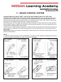
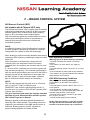
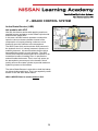
1
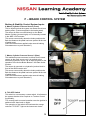
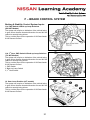
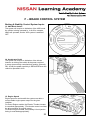
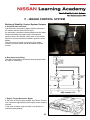
Nissan Australia. September 2009.
Vehicle Stability Control Systems
(ABS, EBD, TCS, VDC, ABLS, HDC, HSA & ABB)
Foreword
The information in this Training Manual should not be interpreted as a basis for
warranty or goodwill claims against Nissan Motor Co. (Australia) Pty. Ltd. (NMA)
unless so designated.
This Technical Training Manual is intended for use by NMA & Nissan
Dealership Technical Personnel. It is not designed for the use by press or for
customer distribution.
Before quoting any specifications be sure to check the relevant Service Manual
and Technical Bulletins.
Right for alteration to data and specifications at any time is reserved. Any such
alterations will be advised by Nissan through Technical and Sales Bulletins.
©2009 Nissan Motor Company (Australia) Pty. Ltd.
Inc. Victoria
Ref: Technical Training Department.
Vehicle Stability Control Systems.
Nissan Australia. September 2009.
F – BRAKE CONTROL SYSTEM
Introduction
This Training Manual is designed to detail the different types of systems that offer enhanced vehicle stability
control & off road ability with the use of Braking Control System technology.
Such systems are as follows;
• Antilock Braking Systems – ABS
• Electronic Brake force Distribution – EBD
• Traction Control System – TCS
• *Vehicle Dynamic Control – *VDC
• Active Brake Limited Slip – ABLS
• Hill Descent Control – HDC
• Brake Assist – BA (This is mechanical only)
• Active Brake Booster – ABB
• Hill Start Assist – HSA
• Enhanced Understeer Control – EUC
* There may at times be cases where VDC is otherwise referred to as the following;
• ESP – Electronic Stability Program
• ESC – Electronic Stability Control
Braking / Stability Control Technology
Vehicles without Off Road Ability
Passenger vehicles such as C11 Tiida & J31 Maxima have varying levels of braking control & vehicle
stability control systems fitted to them. Refer to the chart over the page for more detail.
For such vehicles, normal “on-road” driving conditions can place the vehicle in a situation where the
vehicles direction or it’s ability to stop or maintain control whilst stopping are challenged. Even simple
systems such as Anti Lock Brakes (ABS) can greatly improve the chances for the driver to avoid a
SERIOUS collision.
Additional systems such as Stability Control (VDC / ESP) can further increase the drivers ability to avoid an
accident even when the brake pedal is NOT applied.
Vehicles with Off Road Ability
All Wheel Drive & true Four Wheel Drive vehicles also have varying levels of braking control & vehicle
stability control systems. Refer to the chart over the page for more detail.
For such vehicles, once again normal “on-road” driving conditions can place the vehicle in a situation where
the vehicles direction or it’s ability to stop or maintain control whilst stopping are challenged. However, with
further advancements in braking control technology, the simple action of applying brakes to wheels
WITHOUT input from the driver to control the vehicles speed down steep hills or to simply apply brakes to
one wheel or perhaps 2 wheels that have lost traction can GREATLY enhance the vehicles Off-Road ability.
1
Vehicle Stability Control Systems.
Nissan Australia. September 2009.
F – BRAKE CONTROL SYSTEM
Electronic Braking System Technology Application
2
Vehicle Stability Control Systems.
Nissan Australia. September 2009.
F – BRAKE CONTROL SYSTEM
3 Channel Hydraulic (Braking) Circuit Configuration
A 3 channel Hydraulic Circuit Configuration refers to the hydraulic lines that carry brake fluid under pressure
to the wheels.
In the case of a 3 channel system, there are 3 hydraulic lines. 2 hydraulic lines for the front wheels (1 line to
each individual front wheel) & the 3rd remaining hydraulic line is shared between both rear wheels. However
there still remains 4 x wheel speed sensors.
If for example the left rear wheel locks but no other wheels do, the ABS system will reduce pressure to the
rear wheel braking circuit as a whole. So BOTH rear wheels will have a reduction of braking pressure to
allow the locked left rear wheel to rotate again.
If one of the front wheels lock, then that wheel will individually have it’s hydraulic circuit controlled so that
the wheel can rotate with a more appropriate braking pressure applied to the brake calliper.
A 3 channel configuration typically has a standard ABS system linked to it. Also EBD is often applied to this
type of configuration.
If it is required to have additional systems such as TCS, VDC, ABLS & HDC, a 4 channel configuration will
be required. This is due to the requirement of individual braking control on each wheel.
There is only 1 outlet from the ABS actuator
for the rear. This is the “3rd Channel”
3
Vehicle Stability Control Systems.
Nissan Australia. September 2009.
F – BRAKE CONTROL SYSTEM
4 Channel Hydraulic (Braking) Circuit Configuration
As is the case with a 3 channel configuration discussed previously, a 4 channel braking configuration
system refers to the hydraulic lines that carry brake fluid under pressure to the wheels.
In this case there are 4 hydraulic lines. 2 hydraulic lines for the front wheels & 2 hydraulic lines for the rear
wheels.
As is the case with a 3 channel system, there are 4 x wheel speed sensors.
Therefore (for example) if the left rear wheel locks but no other wheels do, the ABS system will reduce
pressure to the left rear wheel ONLY. ALL of the remaining wheels continue to receive the full &/or
appropriate amount of braking pressure required to slow the rotational speed of the wheel (slow the vehicle
down).
A 4 channel braking configuration typically has a standard ABS / EBD system linked to it. However
additional systems such as TCS, VDC, ABLS & HDC (systems that require a 4 channel braking
configuration) are typically included due to the requirement of individual braking control on each wheel.
These additional systems will vary model to model.
Individual hydraulic circuits are linked to each brake calliper located at each wheel. There are “4 channels”,
one for each of the 4 wheels with their own braking mechanism.
4
Vehicle Stability Control Systems.
Nissan Australia. September 2009.
F – BRAKE CONTROL SYSTEM
Vehicle Stability – General Principles
To ensure the driver is maintains vehicle complete
vehicle control, numerous systems are now available
in order to achieve this.
Traditionally the Anti lock Braking System (ABS) was
designed to offer stability for braking situations only
under conditions when the brake pedal is being
applied.
The next Vehicle Stability development was Traction
Control System (TCS).
This utilised the ability of braking on an individual
wheel, WITHOUT brake pedal input from the driver in
order to stop a spinning wheel. At the same time the
system had other mechanisms in place to reduce
Engine Torque (i.e.; mechanical override of throttle.)
Now new technology takes vehicle stability control a
step further with the development VDC.
The system can now detect the direction the vehicle is
actually moving (Yaw / Side / Decel G Sensor) &
compare with brake pedal & steering wheel activity.
From the activity of these 3 items, VDC can detect a
loss of control situation (panic situation) & make an
attempt to correct the situation (correct vehicle
stability).
CAUTIONS for VDC
• It is NOT possible for VDC to overcome the laws of gravity. Therefore it may
still be possible for loss of vehicle control in extreme circumstances.
• Modified suspension, Exhaust systems, brakes, wheels & tyres can affect
the option of VDC. Typically such modifications will result in the illumination of
the orange “VDC OFF” & “SLIP” lamps on the instrument cluster.
• If snow chains are fitted to the wheels, this will also result in the illumination
of the orange “VDC OFF” & “SLIP” lamps on the instrument cluster.
• When driving in deep snow / mud / sand conditions, switch the VDC OFF.
5
Vehicle Stability Control Systems.
Nissan Australia. September 2009.
F – BRAKE CONTROL SYSTEM
Anti lock Braking System (ABS)
4x4 & non 4x4 models with 3 & 4 Ch. HCC
The Anti-lock Brake System is a function that detects
wheel revolution while braking and it improves
handling stability during sudden braking by preventing
any of the 4 wheels (provided the wheel is supplied
brake fluid pressure individually) from locking.
The braking pressure on each front wheel is separately
controlled however there maybe cases where the rear
wheels are controlled at the same rate of braking
pressure (3 channel braking circuit) regardless of
whether 1 or both rear wheels have locked.
ABS can be applied to a vehicle with a 3 or 4 channel
Hydraulic Circuit Configuration.
Electronic Brake-force Distribution (EBD)
4x4 & non 4x4 models with 3 & 4 Ch. HCC
EBD is a function built into the ABS system that detects
subtle slippages between the front and rear wheels
during braking. It improves handling stability by
electrically controlling the brake fluid pressure which
results in reduced rear tyre slippage.
EBD eliminates the need for the installation of a Load
Sensing Valve (LSV) in passenger carrying models, such
as Y61 wagon.
No additional devices or sensors are installed on EBD
equipped vehicles. It is simply a logic programmed into
the ABS control unit. (I.e.; If both the rear wheels are
rotating at the same slower speed than the front wheels,
then this indicates to the ABS C/U that the rear of the
vehicle has no weight in it therefore tyre traction on the
road is not ideal for braking, therefore pressure to the
rear wheels is evenly reduced in the same manner an
LSV would do.
EBD can be applied to a vehicle with a 3 or 4 channel
Hydraulic Circuit Configuration.
6
Vehicle Stability Control Systems.
Nissan Australia. September 2009.
F – BRAKE CONTROL SYSTEM
ABS Wheel Slip Activity Chart
The chart demonstrates the result of the wheel slipping & what devices act to ensure the wheel remains
unlocked.
7
Vehicle Stability Control Systems.
Nissan Australia. September 2009.
F – BRAKE CONTROL SYSTEM
Traction Control System (TCS)
4x4 & non 4x4 models with 4 Ch. HCC only
The Control Unit detects a wheel spin at either or both of
the drive wheels by comparing wheel speed signals from
all 4 wheels.
At this time, output from ABS Control Unit controls brake
fluid pressure to wheels (applies brake to spinning
wheel) while cutting fuel to engine &/ or closing throttle
valve (dependant on engine type) to reduce engine
torque.
Furthermore, engine power is continuously controlled to
ensure appropriate engine torque is applied to the
driveline at all times.
During TCS operation, it informs the driver of system
operation by flashing the orange coloured “SLIP”
indicator lamp on the instrument cluster.
There are cases where only TCS is applied to the vehicle
model instead of the complete stability control system
(VDC).
NOTE: A 4 channel Hydraulic Circuit Configuration is
required for TCS operation. Models that only have a 3
channel braking configuration are unable to utilise this
technology.
8
Vehicle Stability Control Systems.
Nissan Australia. September 2009.
F – BRAKE CONTROL SYSTEM
Vehicle Dynamic Control (VDC) - 4x4 & non 4x4 models with 4 Ch. HCC only
In addition to TCS / ABS function, VDC detects driver's steering operation, (from the steering angle sensor
which measures speed of turning & actual angle of the Steering Wheel) brake pedal operation (from the
stop lamp switch & brake master cylinder pressure), information from the Yaw / Side / Decel G Sensor and
the speed of each individual wheel from the 4 x wheel speed sensors.
With these inputs, the VDC judges the driving condition (conditions of under steer and over steer) & then it
has the ability to improve stability by individually controlling brake application to the most appropriate of the
4 wheels and controlling engine power output.
Correction of the vehicle stability is achieved in a similar manner that small earth moving vehicles achieve a
steering effect (i.e.; Bobcats). The vehicle is forced pivot on an axis given that only 1 side of the vehicle is
being braked.
During VDC operation, the orange coloured “SLIP” indicator lamp on the instrument cluster flashes to inform
driver of VDC operation.
NOTE:
A 4 channel Hydraulic (braking) Circuit Configuration is required for VDC operation. Models that only have a
3 channel braking configuration are unable to utilise this technology.
9
Vehicle Stability Control Systems.
Nissan Australia. September 2009.
F – BRAKE CONTROL SYSTEM
Enhanced Understeer Control (EUC)
Enhanced Understeer Control will
AUTOMATICALLY apply the brakes to all 4 wheels
in order to reduce the overall vehicle speed and
bring the lateral acceleration below the limit required
by the tyres to maintain grip when the vehicle is
cornering or the vehicle is changing it’s direction.
In other words if the steering wheel is suddenly
turned due to a tighter than expected bend in the
road at a certain speed or higher, the system will
recognise that the speed is too high for the amount
of turn applied to the steering wheel & the VDC
Control Unit will automatically apply braking
pressure to all wheels to slow the vehicle down so
that it can be better prepared to handle the corner.
10
Vehicle Stability Control Systems.
Nissan Australia. September 2009.
F – BRAKE CONTROL SYSTEM
Active Brake Limited Slip (ABLS) - 4x4 models with 4 Channel HCC only
There are cases where 4x4 models do not have the availability of a rear Limited Slip Differential (LSD).
Therefore a system needs to be in place in order to force drive onto a wheel which has the best traction
(grip) possible in the given circumstance.
ABLS has been developed to effectively provide LSD to both front & rear final drive’s. Therefore enhancing
the vehicles Off Road capability.
NOTE: A 4 channel Hydraulic Circuit Configuration is required for ABLS operation. Models that only have a
3 channel braking configuration are unable to utilise this technology.
If the vehicle is on a surface where loss of wheel traction is likely (snow, mud, gravel, grass area etc.), ABLS
can sense that 1 or more of the wheels has lost traction & simply apply the brake to the individual wheel in
order to slow it’s rotational speed (stop it spinning). In turn this action forces drive through the final drive unit
to the opposing wheel which was not spinning. Given that this wheel was not spinning, this would indicate
that it is on a surface with more traction, therefore allowing rotational force to be applied to a wheel that can
gain traction, thus allowing the vehicle to move in the desired direction.
Essentially ABLS is the same as a Traction Control System (TCS) however it’s applied to all 4 wheels.
R51 Pathfinder 4WD Operation (Variants fitted with 4 Channel HCC only)
ABLS has different operating modes dependant on the position of the dash mounted 4WD Selector Switch.
2WD & AUTO Position: ABLS is NOT activated. Normal Traction Control (TCS) takes place in the event of
traction loss to a wheel. Therefore Engine Torque maybe reduced in order to maintain stability.
4H Position: ABLS is activated if slip is detected from a standing start or very low vehicle speed condition.
Engine Torque control is NOT activated.
4LO Position: ABLS is activated if slip is detected from a standing start or very low vehicle speed condition.
Engine Torque control is NOT activated. However a revised Throttle Strategy (less sensitive accelerator
pedal strategy) is applied.
NOTE:
- Wheel slip is detected earlier than it is in 4H mode.
- The orange coloured “VDC OFF” light will illuminate on the instrument cluster. This indicates that the VDC
system has been deactivated when the vehicle is operated in 4L.
- The orange coloured “SLIP” lamp on the instrument cluster will flash whenever ABLS is functioning.
11
Vehicle Stability Control Systems.
Nissan Australia. September 2009.
F – BRAKE CONTROL SYSTEM
Hill Descent Control (HDC)
4x4 models with 4 Channel HCC only
The Hill Descent Control (HDC) system helps to maintain
vehicle speed when driving under 25-35 km/h on steep
downhill grades. HDC is useful when engine braking
alone in 4H or 4L cannot control vehicle speed.
HDC automatically applies the vehicle brakes to control
vehicle speed allowing the driver to concentrate on
steering while reducing the burden of brake and
accelerator operation.
NOTE:
A 4 channel Hydraulic Circuit Configuration is required
for HDC operation. Models that only have a 3 channel
configuration are unable to utilise this technology.
When braking is required on steep downhill roads simply
activate the HDC system by switching the dash mounted
switch ON.
Once the system is activated the orange coloured
indicator light in the instrument cluster will remain
constantly on if all conditions are met (see right for more
detail).
If 1 or more of the conditions are not met the system will
stop operating temporarily. (The indicator light flashes to
warn the driver that conditions are not met for the HDC to
operate) As soon as all conditions are once again met,
the HDC system is ready to function again. (Indicator
light on instrument cluster remains on constantly)
NOTE:
HDC will only operate with the gear lever in a Forward
gear (1st only on T31 MT) or Reverse gear.
HOWEVER, if the vehicle is pointing down the hill, &
then the lever is in reverse, HDC will NOT operate (HDC
indicator light will flash).
The gear selection must match the vehicles intended
direction of travel. Otherwise HDC will NOT operate.
HDC will NOT operate in Neutral.
Braking is applied to individual wheels dependant on
wheel slip rate / wheel speeds. The braking pressure is
supplied by the activation of the ABS actuator motor &
solenoids. Braking pressure is NOT supplied via
pressure being applied to the brake booster.
12
HDC Operating Conditions
(Warning light is on & NOT flashing repeatedly);
• The dash mounted HDC switch is in the ON
position
• The vehicle is on more than a 10% (approx.)
gradient.
• The 4WD selector switch is in the 4H, 4L or LOCK
position.
• If the accelerator or brake pedal is fully released.
• The vehicle is in a gear that matches the intended
rolling direction of the vehicle.
HDC NON Operating Conditions
(Warning light is flashing repeatedly);
• The vehicle is on less than a 6% (approx.)
gradient.
• The 4WD selector switch is NOT in the 4H, 4L or
LOCK position.
• If the accelerator or brake pedal is applied.
• The vehicle is in a gear that does NOT match the
intended rolling direction of the vehicle.
• The gear lever is in Park, Neutral or gear other
than 1st gear (T31 MT).
• Overall vehicle speed is above 35km/h.
NOTE: If the HDC switch is in the OFF position,
the light will NOT be illuminated & the system
will NOT be activated under any circumstance.
Vehicle Stability Control Systems.
Nissan Australia. September 2009.
F – BRAKE CONTROL SYSTEM
Brake Assist (BA)
4x4 & non 4x4 models with ABS / VDC
This system is a simple mechanical device installed
inside the Brake Booster. It is designed to compliment an
ABS braking system, however ABS does not necessarily
require BA to be installed on a vehicle.
BA is NEVER fitted to models without ABS.
Under a panic braking situation, the action of quickly
applying the brake pedal actually compresses a spring &
as a result a valve is opened which in turn releases the
vacuum to the brake pedal side of the booster.
(Atmospheric pressure is now on the brake pedal side of
the booster, but vacuum remains on the master cylinder
side of the booster) As a result a higher force is applied
to the brake master cylinder. That force being the force
of the driver pressing the brake pedal combined with the
force of the booster pushing against the master cylinder
due to imbalance of vacuum inside the booster.
BA is designed to amplify the brake pedal effort given by
the driver. This is an especially useful feature for drivers
who do not have the physical strength to apply a hard
braking effort.
Traditionally it can be quite hazardous to apply too much
brake especially in slippery conditions, now however with
ABS it is more ideal to apply maximum braking effort in
order to trigger ABS activity to occur. BA will ensure that
a sudden application of maximum brake pressure to the
wheels will occur, this in turn causes the wheel to lock
easily. The locked wheel is sensed by the ABS system &
therefore the ABS system takes full control of braking on
the wheels. (Overrides the pressure from the master
cylinder regardless of how much pressure it is out
putting)
13
Vehicle Stability Control Systems.
Nissan Australia. September 2009.
F – BRAKE CONTROL SYSTEM
Active Brake Booster (ABB)
4x4 models with VDC
Like BA, this feature assists with applying maximum
possible booster assistance to the master cylinder with
minimal brake pedal effort.
In this case, the ABS module operates a solenoid to
open the vacuum release chamber instead of the
compression of a spring allowing a sleeve to move
forward & open the chamber to the atmosphere.
The ABS Control Unit monitors brake fluid pressure in
the hydraulic circuit. If a sharp increase in pressure is
suddenly detected, this would indicate that the driver
has applied the pedal in a panic situation. The ABS
Control Unit interprets these signals as a request for an
immediate increase in braking force. It actuates the
solenoid inside the booster. This in turn fully opens up
the atmospheric pressure port in the booster, which
quickly acts on the master cylinder to provide maximum
hydraulic pressure at the brakes.
The Active Brake Booster is also able to hold the brakes
on without brake pedal input. This is an especially useful
feature for the Hill Start Assist feature.
ABB is NEVER fitted to models without VDC.
14
Vehicle Stability Control Systems.
Nissan Australia. September 2009.
F – BRAKE CONTROL SYSTEM
Hill Start Assist (HSA) – Type 1
Models fitted with Active Brake Booster
Vehicle models fitted with the Active Brake Booster
(ABB) system have the availability of Hill Start Assist.
The HSA system automatically keeps the brakes applied
to help prevent the vehicle from rolling backwards in the
time it takes the driver to release the brake pedal and
apply the accelerator when the vehicle is stopped on a
hill. HSA will operate automatically under the following
conditions:
• The selector lever is in a forward or reverse gear.
• The vehicle is stopped completely on a hill (gradient of
5% or more) by applying the brake.
The maximum holding time is 2 seconds. After 2
seconds the vehicle will begin to roll back and hill
start assist will stop operating completely.
To apply braking pressure on the brake master cylinder
without driver input, an electrically controlled solenoid
attached to the brake booster assembly fully opens up
the atmospheric pressure port in the booster, which acts
on the master cylinder to provide maximum hydraulic
pressure at the brakes.
Hill Start Assist (HSA) – Type 2
Models without Active Brake Booster
Type 2 operates in the same manner, however brake
pressure is held at the wheels via the pressure being
trapped at the brakes via the ABS Inlet & Outlet
solenoids.
The drivers brake pedal effort is required to initiate the
brake pressure. Once the vehicle has stopped & meets
the same conditions as the type 1 system, the Outlet
Solenoid remains closed & the inlet solenoid also closes
to keep the pressure at the brakes for the 2 ~ 3 second
period. Then the Solenoids open to gradually release the
pressure.
NOTE for Types 1 & 2:
• HSA will NOT operate when the selector lever is shifted
to N or P or on a flat and level road.
• HSA will NOT operate if the gear position matches the
intended rolling direction. (Will not operate if the vehicle
is pointing down the hill & the gear lever is in “DRIVE” for
example)
• Full vacuum needs to be applied to the Brake Booster
for HSA to work. Therefore the engine must be running.
(Type 1 only)
15
Vehicle Stability Control Systems.
Nissan Australia. September 2009.
F – BRAKE CONTROL SYSTEM
16
Vehicle Stability Control Systems.
Nissan Australia. September 2009.
F – BRAKE CONTROL SYSTEM
Braking & Stability Control System Inputs
1. Stop Lamp Switch
This is a critical input for all types of Braking & Stability
Control Systems.
This switch is an indication of the drivers intentions in
order for the system to be prepared for the most
appropriate type of braking & / or stability control.
2. Wheel Speed Sensors
There are currently 2 types of wheel speed sensors
in use across the model range;
(i) Tone Wheel Type Sensor;
Control unit sends electric power to a sensor detection
circuit. The sensor detects the rotation by using a semiconductor that changes the resistance value by the
contact from magnetic lines of force.
These are typically used on rear wheels.
(ii) Magnetic Encoder Type Sensor;
The speed of rotation is detected by the use of an IC in
the sensing portion and a magnetic rotor.
Power is supplied to the sensing circuit to read magnetic
lines of force and the magnetic force is sensed
electrically and converted to an electrical signal.
When the sensor rotor turns, the magnetic field changes.
The change is converted to an electrical signal and
transmitted to the ABS actuator control unit.
The change of the magnetic field is proportional to the
wheel speed.
The Magnetic type allows for a smaller size and the
weight is reduced.
These are typically used on front wheels.
17
Vehicle Stability Control Systems.
Nissan Australia. September 2009.
F – BRAKE CONTROL SYSTEM
Braking & Stability Control System Inputs
3. Decel G Sensor (Single Axis G Sensor)
Under a braking situation, the Decel G Sensor can detect
the rate of speed loss (how fast the vehicle is slowing
down) If the rate is slow, this would indicate that the
vehicle is braking on a low friction road surface (gravel
for example). The sensor can indicate that the cycle rate
of the ABS is not suitable for the road conditions
therefore the cycling rate is changed in order to improve
the braking ability on such a surface.
This Sensor is typically located in the centre of the
vehicle under the centre console.
Do NOT confuse this sensor with the below
discussed Yaw / Side / Decel G Sensor
4. Yaw / Side / Decel G Sensor (Tri Axis G Sensor)
This sensor has additional capabilities over the Decel G
Sensor. It can detect the rate of speed loss as well as the
turning direction of the vehicle vs actual direction of
vehicle travel.
With this information, the VDC Control Unit can
determine what actions it needs to take (what wheel /
wheels to apply braking to for example) so that the
vehicles direction can be corrected & the vehicle is
therefore stabilised.
It can also detect the level of gradient (how steep) the
vehicle is on to assist with Hill Start Assist & Hill Decent
Control functionality.
This Sensor is typically located in the centre of the
vehicle under the centre console.
5. Steering Wheel Angle Sensor
This input is important for VDC. The intended direction of
the driver (steering wheel angle) is checked against the
actual direction of the vehicle by the Control Unit. The
appropriate braking is applied to the necessary wheels in
order to correct the vehicles direction of travel.
The rate / speed that the wheel is being turned is also
monitored.
18
Vehicle Stability Control Systems.
Nissan Australia. September 2009.
F – BRAKE CONTROL SYSTEM
Braking & Stability Control System Inputs
6. Master Cylinder Pressure Sensor (Front)
This is utilised so that the system can detect the drivers
braking effort. (Pressure applied to the brake pedal).
The sensor is either mounted directly on the Brake
Master Cylinder (pictured right) or it is internally located
in the ABS / VDC actuator.
This sensor can actually detect the brake pedal stroke.
Both the distance the pedal has been pushed & the rate
of pedal travel.
(Have the brakes been applied under normal braking
circumstances or a panic situation?)
7. Master Cylinder Pressure Sensor 2 (Rear)
This additional pressure sensor is utilised for the same
reason as the main sensor only it is applied to the
secondary hydraulic circuit. It is an input required for the
operation of the Active Brake Booster / Hill Start Assist
function.
The sensor is mounted on a hydraulic junction block in
front of the ABS Actuator unit.
This sensor can actually detect the brake pedal stroke.
Both the distance the pedal has been pushed & the rate
of pedal travel.
(Have the brakes been applied under normal braking
circumstances or a panic situation?)
8. TCS OFF Switch
This switch is a momentary contact switch. It indicates to
the system that the driver requires no Traction Control
functionality.
TCS reverts back to normal operation once the ignition is
switched off & then back on again.
The operation of the switch will illuminate the orange
coloured “TCS OFF” light on the instrument cluster.
19
Vehicle Stability Control Systems.
Nissan Australia. September 2009.
F – BRAKE CONTROL SYSTEM
Braking & Stability Control System Inputs
9. VDC / ESP OFF Switch
This switch is a momentary contact switch. It indicates to
the system that the driver requires no Vehicle Stability
Control functionality.
VDC reverts back to normal operation once the ignition is
switched off & then back on again.
The operation of the switch will illuminate the orange
coloured “VDC / ESP OFF” light on the instrument
cluster.
10. HDC (on) Switch
This switch is a permanent contact 2 stage switch. It
indicates to the system that the driver requires HDC
functionality.
The operation of the switch will illuminate the orange
coloured HDC light on the instrument cluster. If there is a
condition that does not satisfy the proper operation of
HDC, the light will constantly flash.
20
Vehicle Stability Control Systems.
Nissan Australia. September 2009.
F – BRAKE CONTROL SYSTEM
Braking & Stability Control System Inputs
11a. PNP Switch & Back-up Lamp Switches
(R51 M/T Models)
The system will require an indication of the vehicle being
in gear & from that the intended direction of travel & if the
vehicle is actually being driven.
This is a critical input for the operation of Hill Start Assist
& Hill Descent Control.
11b. 1st Gear, PNP Switch & Back-up Lamp Switches
(T31 M/T Models)
The system will require an indication of the vehicle being
in gear & from that the intended direction of travel & if the
vehicle is actually being driven.
This is a critical input for the operation of Hill Start Assist
& Hill Descent Control.
1; PNP Switch
2; Back-up Lamp Switch
3; 1st Gear Switch
12. Gear Lever Position (A/T models)
The system will require an indication of the vehicle being
in gear & from that the intended direction of travel & if the
vehicle is actually being driven.
This is a critical input for the operation of Hill Start Assist
& Hill Descent Control.
21
Vehicle Stability Control Systems.
Nissan Australia. September 2009.
F – BRAKE CONTROL SYSTEM
Braking & Stability Control System Inputs
13. 4WD Mode Switch
The system will require an indication of the 4WD mode
the vehicle is being operated in. In 4LO for example,
ABLS will operated, but the VDC system is switched
OFF.
14. Accelerator Pedal
The system will require an indication of the drivers
intention on driving the vehicle & the power required.
In some electronically controlled 4x4 models, (primarily
R51 & D40) the pedal sensitivity is REDUCED when the
vehicle is operated in 4LO.
15. Engine Speed
Engine speed is monitored & the system can tailor a
more suitable engine power output for the given
condition.
For Petrol Engine models, the Electric Throttle Actuator
is controlled appropriately. (The throttle control overrides
the drivers wishes for engine power)
For Diesel Engine models, fuel quantity & fuel injection
timing is controlled appropriately.
22
Vehicle Stability Control Systems.
Nissan Australia. September 2009.
F – BRAKE CONTROL SYSTEM
Braking & Stability Control System Outputs
1. Pump Motor
The pump motor is utilised to create fluid pressure & then it is applied to any brake unit on a wheel where
required. The pump is utilised on models with standard ABS systems as well models with additional
functions such as stability control (VDC) & 4x4 braking control (ABLS).
For example, when a vehicle fitted with VDC is cornering & begins the skid out of control, the pump motor is
activated so that there is available brake fluid pressure to apply to any given wheel to control the vehicle’s
stability. The driver does NOT have to apply master cylinder pressure to create a braking action in this case.
2. Inlet Solenoid
The inlet solenoid is controlled in 2 x ways;
(i) Remain in a normally open position (switched off) so that brake fluid is allowed into the brake unit
(calliper / wheel cylinder) from either the brake master cylinder (due to the driver pushing the brake pedal) or
the ABS pump forcing fluid into the brake unit. The outlet solenoid however must be in the closed position.
(ii) Switched on & moves to the closed position. This will stop fluid pressure being applied to the brake unit.
If the Outlet solenoid remains closed as well, this will keep a “hold” pressure on the brake unit at the wheel.
3. Outlet Solenoid
The Outlet solenoid is also controlled in 2 x ways;
(i) Remain in a normally closed position (switched off) so that brake fluid is not allowed to escape from the
brake unit (calliper / wheel cylinder).
(ii) Switched on & moves to the open position. This will allow fluid pressure applied to the brake unit to
escape. (Allow the wheel to rotate freely) The inlet solenoid should be in the closed position however to stop
fluid pressure being applied to the braking unit.
4. Primary Switch Over Valves
The switch over valves are operated under VDC, ABLS & HDC operating conditions. They are designed to
stop fluid pressure being forced back into the master cylinder when braking pressure is applied to a brake
unit at any wheel under a stability control condition.
23
Vehicle Stability Control Systems.
Nissan Australia. September 2009.
F – BRAKE CONTROL SYSTEM
Braking & Stability Control System Outputs
5. Active Booster Solenoid
The Solenoid is activated to apply booster pressure to
the master cylinder without driver input.
An electrically controlled solenoid attached to the brake
booster assembly fully opens up the atmospheric
pressure port in the booster, which acts on the master
cylinder to provide maximum hydraulic pressure at the
brakes.
The solenoid is mounted on the front of the brake
booster just below where the Brake Master Cylinder
mounts.
6. Rear Stop Lamp Relay
The relay is operated to illuminate the stop lamps when
the HDC is functioning.
7. Engine Torque Reduction Signal
In the case of Petrol engine models, the Electric Throttle
unit is operated appropriately and engine power output is
reduced.
In the case of Diesel engine models, fuel injection is
controlled appropriately.
24
Vehicle Stability Control Systems.
Nissan Australia. September 2009.
F – BRAKE CONTROL SYSTEM
Braking & Stability Control System Outputs
8. Brake Warning Lamp
This light will switch on for the following 3 reasons;
• Hand Brake is applied
• Brake fluid level is low
• Ignition ON (engine not running) bulb check function
9. ABS Warning Lamp
This light will switch on for the following 2 reasons;
• An ABS related fault has been detected
• Ignition ON (engine not running) bulb check function
10. TCS OFF Warning Lamp
This light will switch on for the following 3 reasons;
• An ABS / TCS related fault has been detected
• The TCS OFF switch has been pressed once
• Ignition ON (engine not running) bulb check function
11. VDC OFF Warning Lamp (or ESP OFF)
This light will switch on for the following 4 reasons;
• An ABS / VDC related fault has been detected
• The VDC OFF switch has been pressed once
• The 4LO position on the 4WD mode switch has been selected (where applicable)
• Ignition ON (engine not running) bulb check function
12. SLIP Warning Lamp
This light will switch on for the following 4 reasons;
• An ABS / TCS related fault has been detected (stays on constantly)
• A wheel slip / spin condition is being detected (flashes)
• The vehicle is in an unstable driving condition, so engine torque reduction & braking is being applied to 1
or more wheel(s)
• Ignition ON (engine not running) bulb check function
13. HDC (on) Warning Lamp
Light will switch on for the following 2 reasons;
• The HDC switch is in the ON Position, the 4WD switch is in the 4H or 4LO position, the vehicle is on a
suitable enough gradient, the transmission is in gear & the accelerator pedal & brake pedal is NOT applied.
NOTE: If the HDC switch is on, but the other conditions stated are not met, the light will flash repeatedly
• Ignition ON (engine not running) bulb check function
25
Vehicle Stability Control Systems.
Nissan Australia. September 2009.
F – BRAKE CONTROL SYSTEM
Normal Incidences which May Cause Customer Complaint
ABS (All Variants)
• When starting engine or just after starting vehicle, brake pedal may vibrate or the motor operating
noise may be heard from engine room. This is a normal state of the operation check.
• During ABS operation, brake pedal lightly vibrates and a mechanical noise may be heard. This is
normal.
• Stopping distance may be longer than that of vehicles without ABS when vehicle is driven on rough
surfaces, loose gravel or snow-covered (fresh / deep snow) roads.
TCS
• During TCS operation, body and brake pedal lightly vibrate and mechanical noises may be heard. This
is normal.
• Depending on road circumstances, driver may sense a sluggish engine response. This is normal,
because optimum traction (achieved by reducing engine power) has highest priority under TCS
operation.
• When vehicle is passing through a road where surface friction coefficient varies, downshifting or
depressing accelerator pedal fully may activate TCS temporarily.
VDC
• During VDC operation, body and brake pedal lightly vibrate and mechanical noise may be heard. This
is normal.
• If vehicle is rotated on turn table, or rolled and rocked on a ship or vehicle transport ferry, ABS warning
lamp, VDC OFF indicator lamp and SLIP indicator lamp may turn on. In this case, start engine on normal
road again. If ABS warning lamp, VDC OFF indicator lamp and SLIP indicator lamp turn off after restart,
it is normal.
• When under rapid acceleration or hard turn conditions, operating noise by brake pedal is generated
due to momentary activation of TCS &/or VDC. This is not malfunction because TCS and VDC are
functioning normally.
• When driving on a steep slope such as an embankment, ABS warning lamp, VDC OFF indicator lamp
and SLIP indicator lamp may turn on. In this case, start engine on normal road again. If ABS warning
lamp, VDC OFF indicator lamp and SLIP indicator lamp turn off after restart, it is normal.
• A malfunction code orientating around Yaw / Side / Decel G Sensor may occur under hard turn like
spin turn, rapid acceleration turn, drift run, etc when VDC function is OFF (“VDC OFF” switch is in “ON”
position). This is not malfunction if it is possible to return to a normal position after restarting engine. It
will however be necessary to erase the memory of self-diagnosis.
26
Vehicle Stability Control Systems.
Nissan Australia. September 2009.
F – BRAKE CONTROL SYSTEM
Typical Service & Trouble Diagnosis Procedures
1. Wheel Speed Sensors
• Ensure they are mounted securely & the wiring & connectors are not damaged.
• Ensure that the tone wheel is not damaged & is mounted securely.
• Ensure that no metallic material / debris is caught on the tone wheel.
• Ensure that all wheel sizes are correct
2. ABS Power & Ground Connections
• Ensure that the main ABS actuator ground connection is clean &tight. Typically a poor ABS ground will
cause CAN related DTC’s & other intermittent faults.
• Ensure that all relays & fusible links are securely connected & connections are clean & tight.
3. Steering Wheel Angle Neutral Position setting (VDC / ESP only)
• Ensure that this is correctly reset via CONSULT in Work Support. Typically this should be carried out
after any front end repairs / wheel alignment etc. For R51 this is required after a battery disconnection.
4. Calibration of Decel G Sensor (R51 with VDC only)
• Ensure that this is correctly reset via CONSULT in Work Support. Typically this should be carried out
when carrying out an inspection on the operation of hill descent control &/or hill start assist.
5. Correct Adjustment / Setting of Brake Pedal & Brake Pedal Switches
Numerous problems related to the operation of the braking system (both hydraulically & electrically) can
occur if the brake pedal free play / brake pedal stopper clearance / stop lamp &/or ASCD cut switches
are not set correctly.
• Use Data Monitor Engine as well as Data Monitor ABS to determine correct switch operation.
• Refer to the Service Manual for correct pedal height / free play adjustments.
• Ensure stop lamps are operating correctly.
6. Gear Position Inputs
Numerous problems can occur on vehicles fitted with VDC / HDC / HSA can occur if the system does
not receive the correct gear position signals.
• Use Data Monitor to ensure that all gear position signals are being input correctly.
27