1
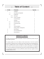
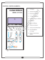
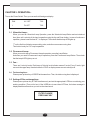
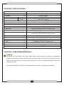
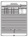
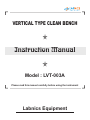
VERTICAL TYPE CLEAN BENCH
Instruction Manual
Model : LVT-003A
Please read this manual carefully before using the instrument
Labnics Equipment
POINTS TO ENSURE SAFETY :
You must read the table given below before using the Clean Bench LVT-003A . If you have any
trouble with the Clean Bench during an operation, please check the symbols and following
instructions given in the manual book.
Symbol & Definition :
Symbol
Definition
Precaution
It could result in damage to your clean bench.
Warning
It could result in an accident or personal injury.
Table of Content
Sr.No.
Contents
Pg. No.
1
Installation
1
1.1
Unpacking and Inspection
1
1.2
Preparation
1
1.2.1
Placement
1
1.2.2
Power Connection
2
Control Elements
2
3
Operation
3
3.1
Ultraviolet Lamp
3
3.2
Fluorescent Lamp
3
3.3
Fan
3
3.4
Total running time
3
3.5
Setting of Filter exchange time
3
4
Specifications
4
5
Care and Maintenance
4
6
Service Manual
5
WARRANTY & SERVICE
LVT-003A is warranted by LABNIC EQUIPMENT PRIVATE LIMITED for a period of one year
from the date of purchase.
The warranty applies only to the defects or faults caused due to the fault of product
workmanship or materials, and is not valid for the defects resulting from accidental damage,
misuse or negligence and in case of alternations or repair carried out by an unauthorized
person. Service under the warranty is provided only upon the presentation of a declaration
form. Service is available in all countries where the product is officially distributed by LABNICS.
If you need further information or have any difficulties, please contact your supplier or directly
to LABNICS EQP. PVT. LTD.
CHAPTER 1. INSTALLATION:Precaution: If you make a discretionary alternation of Clean Bench or use it differently from its own functional
purpose, it could cause the fault of Clean Bench or an accident.
1.1 Unpacking and Inspection:Remove all the packing materials and check your clean bench. If clean bench LVT-003A is either damaged or
have some problem, do not try to repair it by yourself. Immediately contact your supplier or LABNICS.
1.2 Preparation:-
1.2.1 Placement:-
Place the Clean Bench on clean, dry, horizontal and vibration-free
location. Don't move it during the operation.
1.2.2 Power Connection:-
WARNING: Verify that the Clean Bench power matches your electrical source. Otherwise, it could cause an electric
accident or could result in damage to the Clean Bench.
Check the rear part of Clean Bench.
Check that the power switch is off and then connect the plug to the power point or connecter.
-1-
CHAPTER 2. CONTROL ELEMENTS:-
CLEAN BENCH
MODEL: LVT-003A
1
U.V.
F.L.
2
RESET
POWER
3
6
LCD Display
2.
Ultraviolet Lamp's LED
3.
Fluorescent Lamp's LED
4.
U.V Lamp On/ Off Button
5.
Fluorescent Lamp On/ Off Button
6.
Reset Button
7.
Power On/Off Button
8.
Velocity Level Indicator
9.
Velocity Level Up/Down Button
7
5
4
1.
10. Timer Setting Button
(U.V. Lamp)
8
10
SPEED
TIME
11. Remote Controller Sensor
(Option)
8
AIR FLOW RATE
REMOTE 11
-2-
CHAPTER 3. OPERATION:Turn on the Power Switch. Then you can see the followings on display:
FAN
UV : OFF
T: 00
1
FL: OFF
T: 00
3.1 Ultraviolet Lamp:When you need an Ultraviolet Lamp Operation, press the Ultraviolet Lamp Button and set a desired
time (time unit is minute) of the lamp's operation using the Up and Down button. In case of continuous
operation, please lower the time till *:* is displayed. Then check that the lamp LED lights up.
“T” on the first line of display means setting value, and other one means running time.
Time button is only for U.V. Lamp's operation.
3.2 Fluorescent Lamp:When you want to stop a Fluorescent Lamp's operation, press the Lamp Button.
And when you need a Fluorescent Lamp's operation, press the Fluorescent Lamp Button. Then check
that the lamp's LED lights up or not.
3.3 Fan:There are 9 velocity levels. Each lamp of Velocity level indicator means 3 levels. Every 3 levels, light
moves to the upper lamp. Number below the "FAN" on display means current velocity level.
3.4 Total running time:Please press up/down key of SPEED at the same time. Then, the total running time is displayed.
3.5 Setting of Filter exchange time:Please press up/down key of TIME simultaneously and set the appropriate LIFE time considering your
working condition. (Time unit is hour) If the USED time is more than LIFE time, the below message is
displayed with an alarm when you turn on the clean bench.
FILTER CHANGE
PRESS ANY KEY
-3-
CHAPTER 4. SPECIFICATIONS:Model
LVT-003A
Flow Type
Vertical Air Flow Type
Features
General Purpose
Dimensions (mm)
Main Control
Inner
1220 x 600 x 700 (H)
Outer
1300 x 990 x 1850 (H)
Full Digital Microprocessor Control With Touch Pad
Winding Velocity
0.3-0.5m/Sec, 10 Stage Adjustable
Purity
Class 100
Display
Main Filter
Back Light LCD Digital Display
HEPA Filter/0.3Micron 99.99% Efficiency Filter
Pre Filter
High Efficiency Nylon Material, Internal Mounted
Material
Working Table : Stainless Steel
Clean Bench: Steel Plate With Powder Coating
Illumination
40W Fluorescent Lamp x 2EA
UV Lamp
40W x 1 Set, 15W x 1 Set
Timer
Electronic Digital Timer, 99min or Hold
Utility
Receptacle, Gas Cock, Vacuum Cock
Door
Sliding Glass Door, Tempered Safety Glass
Power
220V, 50Hz
Catalog No.
24110301
CHAPTER 5. CARE AND MAINTENANCE:WARNING:
Disconnect the Clean Bench from power supply before making attempt for cleaning or maintenance
procedures. After use the Clean Bench should be wiped down with a soft cloth. Do not immerse the Clean
Bench or pour liquids over it, as electrical shock may occur. Clean up any spills immediately by taking the
proper precautions.
To ensure the long life of Clean Bench, it should be used in a dry and non-aggressive environment.
-4-
SERVICE REPORT
Tel.No.:
Customer’s Address :
Fax No.:
Weekly Off.:
Dept.:
Contact Person / Designation :
Time
Date
From
To
System
Configuration
Date :
Model
SR. No.
Serial No.
Status : OK
Installation
Not OK
Warranty
Demonstration
Maintenance
Contract
Repairs
Application
Billable
Calibration
Validation
Courtesy
Nature of Problem :
Observation & Action Taken :
Customer’s Remarks :
Parts Replaced :
Parts Recommended / Action Required : Yes
No
Service Engineer’s Name & Signature
Requisition Number :
Customer’s Name, Signature, Date & Stamp
Page ____ Of ____
-5-