1
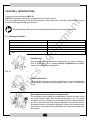
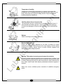
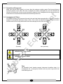
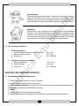
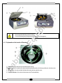
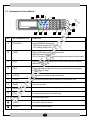
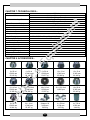
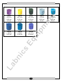
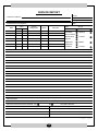
MULTI-PURPOSE CENTRIFUGE Instruction Manual Model : LMPC-10 Please read this manual carefully before using the instrument Labnics Equipment Table of Content CHAPTER CONTENT 1 Intended Application 1 2 Notes on Safety 1 3 Introduction 2 3.1 Delivery check list 2 3.2 Notes for Installation 2 3.3 Electricity safety information 4 3.4 Precaution 4 3.5 Maintenance information 4 3.6 Regulations 4 3.7 Prevention of over speed 5 3.8 Arrangement of tubes 5 3.9 Use and storage condition 6 Explanation for Device 6 4.1 Explanation for external appearance 6 4.2 Explanation of the inside of chamber 7 4.3 Explanation for control board 8 Operation Procedures 9 5.1 Space requirement 9 5.2 Connection to the mains 9 Maintenance 9 6.1 Care and cleaning 9 6.2 Storage 10 6.3 Decontamination 10 6.4 Troubleshooting 10 7 Technical Data 11 8 Accessories 11 9 Service Report 13 4 5 6 PAGE No. CHAPTER 1. INTENDED APPLICATION:This centrifuge is used for separating substances and mixtures with a density of up to maximum 1.5g/ml. CHAPTER 2. NOTES ON SAFETY:Before operating the centrifuge you should read and pay attention to the following instructions. 1. Along with the operating instructions and the legal regulations on accident prevention, you should also follow the recognized professional regulations for working in a safe and professional manner. 2. These operating instructions should be read in conjunction with any other instructions of the country where this device is to be used. 3. This centrifuge is extremely safe to operate. 4. However, it can lead to danger for users or others if used by untrained staff, in an inappropriate way or for a purpose other than that it was designed for. 5. This centrifuge should be installed on a good and stable base. 6. Ensure that neither a person nor any dangerous material should be present within the safe zone of 3M around the equipment when the centrifuge is running. 7. Loads centrifuge rotor evenly. All positions on rotor must be filled. 8. Do not fill centrifuge containers inside the centrifuge. 9. Centrifuge containers must not be filled beyond the capacity specified by the manufacturer. 10. The centrifuge may only be operated when the balance is within the bounds of acceptability. 11. The centrifuge must not be operated in an area subjected to the danger of explosions. 12. The centrifuge must not be used with inflammable or explosive materials or materials that react with one another producing a lot of energy. 13. If users have to use hazardous materials or compounds contaminated with toxic, radioactive or pathogenic micro-organisms, they must take appropriate measures. 14. The centrifuge must not be operated with highly corrosive substances which could impair the mechanical integrity of rotors, hangers and accessories. 15. Any rotors, hangers or accessories showing clear signs of corrosion or mechanical defects must not be used with centrifuge. 16. Repairs must only be carried out by personnel authorized to do so by the manufacturer. 17. Only original spare parts and original accessories licensed by the Labnics Equipments Pvt. Ltd. are allowed to be utilized. 18. In case of fault or emergency release, never touch the rotor before it has stopped turning. 19. The safe operation and reliability of centrifuge can only guaranteed if : The centrifuge is operated in accordance with the operating instructions. The electric installation on the site where the centrifuge is installed conforms to the demands of Labnics stipulations. No claims under the guarantee will be considered by the manufacturer unless the above instructions have been adhere to. -1- CHAPTER 3. INTRODUCTION:Thank you for your selection of LMPC 10. LMPC 10 is a desktop centrifuge thus refrigeration function does not exist. This user manual informs the user about the solutions, daily maintenance, preventive measures and working methods for the proper handling of instrument. Before operating centrifuge you should read and pay attention to the operating instructions. 3.1 Delivery Checklist:Items Main body Connected cable Instruction manual Wrench Fuses Quantity 1 1 1 1 1 Packing List After receiving package examine the centrifuge for any kind of damage or lack of spare parts, if any contact Labnics Equipments immediately. Contacts are written on the package box. 3.2 Notes for Installation:- Stable and Flat Place Centrifuge should be kept on the hard and flat floor. In case of inclined base wheel is likely to get bent by heavy weight of rotor, since it is rotated long hours. Space Requirements and Proper Circulation of Air The centrifuge must be placed in a suitable space, so that it is stable. During set up the required safety area around the centrifuge is 3m. For proper circulation of air, the centrifuge should be kept at a place so that it has space of 15cm on both sides and 10cm of space at the back. If the draft hole present at the back of device is blocked by hiding with clothes or is blocked by some other device, air circulation will be difficult and also avoids place where more dust is there. -2- Temperature, Humidity Centrifuge is influenced by temperature or external environment like humidity etc. as it is operated by highly electronic control system. Do not keep it near direct ray of light or heating utensils. Proper temperature, humidity should be maintained. The Place Not to Occur Corrosive Gas The centrifuge is set up in a place where corrosive gases don't occur. If sulfur dioxide and chlorine gas etc.. comes in contacts with centrifuge, corrosion and damages of various metal segment of rotor and shaft can occur. Balance Shaft of centrifuge must work horizontally. Electrical Requirements Please use rated voltage registered on the label of product for normal functioning of device. Please enquire at the local supply of electric power company or customer support center & confirm whether engaged rural districts fits in rated voltage of product. Warning: This product connects ground connection certainly. Plug the protection ground connection pin to product which is offered, and then this plug should be inserted to ground connection way electricity outlet for safety. Exchange this plug for ground connection in case it doesn't fits to busy outlet. Avoid shock and enquire professional electrical engineer if required. When error occurs, withdraw power connection & establish emergency switch. -3- 3.3 Electrical Safety Information:Please use supply cord offered with equipment. Supply cord is inserted to electricity outlet that is grafted at near by place. Extension code doesn't get used up. Please enquire with professional engineer to confirm whether outlet is grounded. Wrong ground connection may cause shock. Please set up the equipment so that supply cord does not step on. Avoid ventilation openings blockage. Please do not insert any object in slot or hole of equipment. Please turn off the power of equipment immediately and select supply cord in outlet in case of following circumstances. Please contact our company customer support center also. - Strange noise or smell coming from the equipment. - If supply cord get damaged or get worn away. - If wall circuit breaker, fuse or other safety device gets expired. - Liquid spill occur in equipment. - If water infiltrates in equipment. - If some part of equipment is damaged. 3.4 Precaution:This machine is designed by keeping in mind user's safety. Danger territory has lapped cover or protection apparatus that can be removed only by using tools so that user may not approach. Please do not remove cover or protection apparatus absolutely. 3.5 Maintenance Information:Product maintenance procedure is offered with the product. Please do not enforce product maintenance procedure that is not clarified in user description section. Please do not use jet-type cleaner. If used then it may affect the performance of equipment and may also create critical condition. Please use offered width and cleaning article to clear the statement of user description. Keep these articles away from children's. Do not remove fixed cover or protection apparatus absolutely with screw. Spare parts inside the frame are the parts that are not maintained or fixed. 3.6 Regulations:Read all cautions and guidelines offered with equipment certainly. Equipment should be placed in a well ventilated and spacious area. Please refer to establishment guideline for size of minimum establishment space. Please use only refined articles and parts of Labnics Equipment. Faulty use can affect consumer goods and performance. Please select plug in outlet certainly before execute cleaning. Power cable that segregates the power of equipment is connected by plug-in unit at the back of equipment. Please select all cables on electricity outlet if you want to shut off the power of equipment properly. -4- 3.7 Prevention of Overspeed:Make sure that the Rotor speed is not more than the maximum rotation speed. Don't exceed beyond maximum speed of rotor. When the rotor is subjected to relative centrifugal force over the allowed seal intensity, the destruction of rotor occurs because the shape of rotor is designed so that rotor can stand an external force in accordance with the allowed seal intensity of the rotor. 3.8 Arrangement of Tubes:Put samples exactly to be measured into each tube and load tubes symmetrically in the rotor so that the samples in the opposite tubes have same volume. If the volume of opposite samples is different, serious turbulence will occurs during rotation and it can cause damage to motor, rotor and shaft. Symmetry Non-symmetry Indication for danger and alert Indication for electric shock Fuse An automatic circuit breaker protects instrument circulation when it is overpowered. Ex. In emergency situation such as power surge which can cause damage to unit. -5- Lid rock device This centrifuge has lid control sensor. If lid opens, turning of rotor suspends rapidly, and the device will not work in case door is not properly closed. Automatic door lock function is designed so that the lid doesn't get opened when centrifuge is running except artificial opening by using manual method. Imbalance During turning of rotor, if imbalance occur and it goes beyond the constant level then it is sensed that damage may occur which is measured by the vibration of motor and thus get suspends according to deceleration time that is entered before with alarm sound. Such safety device prevents accidents during operation when experimenter operates centrifugal separator. 3.9 Use and Storage Condition:1. 2. Working conditions:Use encouragement within room temperature : Maximum relative humidity : Air pressure : 5℃ ~ 35 ℃ 30 %~ 85% 500 ~ 1060 hpa Storage or conveyance conditions:Ambient temperature : Relative humidity : Air pressure : -10℃ ~ +40℃ 10 %~ 90% 500 ~ 1060 hpa CHAPTER 4. EXPLANATION FOR DEVICE 4.1 Explanation for External Appearance:① Lid: It is a lid that give protection to inside of chamber. ② Lid Pin: It is fixed in the lid pin hall to keep in state. ③ RPM Confirmation Window: It is a region that can measure the rotor speed by digital speedometer etc. ④ Chamber: Space where rotor is installed and running. ⑤ Rotor ⑥ Lid Pin Hole: It's a place where lid pin is mounted. ⑦ Control panel: It's a controlling element for establishment, temperature and speed Control etc.. -6- - Do not open the lid when rotor is running. Do not use emergency lid open key except in case of emergency. 4.2 Explanation of the Inside of Chamber:- ① Chamber: Space where rotor is installed and running. ② Motor Cover: It is a device for noise reduction and prevention of inflow impurities etc. into the motor. ② Motor Axis: It is a device that is linked with motor and can spin the rotor. ④ Rotor ID Sensor: It is a device that sense rotor ID automatically. -7- 4.3 Explanation for Control Board:1 2 3 4 1 2 3 CHECK 4 5 6 PROG. 7 8 9 SAVE ± 0 CE ENTER TIME RPM / RCF ACC DEC START STOP DOOR 5 6 12 No. BUTTON/ INDICATOR 11 10 9 8 7 FUNCTION [RPM / RCF] display RPM/RCF setting value - RPM Setting / Display Unit : 1 RPM - RCF Setting / Display Unit : 1 x g [TIME] Display TIME setting value and it can set upto 99hrs59minutes and 59sec 0:0:0=>Free Run Function. It used to change & store each functional parts. [ACC] Display acceleration step and user can use accelerating time changing randomly from 0~9 step. [DEC] Display deceleration step and user can use accelerating time changing randomly from 0~9step. [CHECK] On operating, can check set value and stored. [PROG] Display stored number and can stored up to 100 places(0 ~ 99). [SAVE] Can save set value [ENTER] [CE] Can erase set value when user set wrong <DOOR> It is used to open the lid. <STOP> It is used to stop the machine. <START> It is used to start the machine. -8- CHAPTER 5 OPERATION PROCEDURES :5.1 Space Requirement:The centrifuge must be set up in a suitable place, so that it is stable. Avoid presence of any person and hazardous material near the centrifuge. Do not place any object in front of the ventiduct. 5.2 Connection to the Mains:Check whether the supply voltage, supply frequency and on-site mains fuse agrees with the specification given on the nameplate. The nameplate is located on the left side of the centrifuge. Make sure that the mains switch is in the “0” position. The centrifuge must be connected to a standard mains socket using the power supply cable provided. Installation and removal of the rotor. Clean the rotor shaft and the rotor drilling. Then lightly grease the motor shaft afterwards. Dirt particles between the motor and the rotor hinder a perfect seating of the rotor and cause an irregular operation. Place rotor vertically on the motor shaft. The motor shaft dog has to fit in the rotor slot. The alignment of the groove is labeled on the rotor. Tighten the rotor tension nut with the supplied wrench by turning in a clockwise direction. Loosening the Rotor: Loosen the tension nut by turning in a counter clockwise direction and turning until the working point. After passing the working point for lifting the rotor is loosened from the motor shaft cone. Turn the tension nut until the rotor is able to be lifted from the motor shaft. Only original spare parts and original accessories licensed by the Labnics Equipment are allowed to be utilized Only original spare parts and original accessories licensed by the Labnics Equipment are allowed to be utilized. CHAPTER 6. MAINTENCNCE:This chapter explains how to keep your unit in a good operating condition. It includes instructions for cleaning, decontamination and storing. This chapter also covers the cover interlock by pass. 6.1 Care and Cleaning:Keep your centrifuge clean to ensure good operation and to extend its life. Clean the sample chamber, rotor and lid at the end of each working day and immediately after any spill. To clean the chamber, use a damp sponge, warm water, and a mild liquid detergent, suitable for washing dishes by hand. Don't use caustic detergents or detergents that contain chlorine ions. These will attack metals. -9- - - Remove stubborn stains with a plastic scrub pad. Don't use steel wool, wire brushes, abrasives, or sandpaper. They create corrosion sites. Never pour water directly into the rotor chamber. Scrub the rotor's tube cavities with a stiff test tube brush that has end bristles and a non-metallic tip. Dry each part after cleaning with a clean, absorbent towel. If glass breakage occurs, remove all broken glass embedded in the plastic or rubber accessories. Glass particles can come in contact with new glass tubes, creating pressure points that may results in breakage recurring. Glass particles in the chamber grind to a fine gray dust during centrifugation. This dust can coat the inside of centrifuge. 6.2 Storage:Store the part on a soft surface to avoid damage. Rotors and other parts should be clean and dry. Store them so that they are open to air, not in a plastic bag, so that any residual moisture get evaporates. Face the parts upward to avoid moisture retention in the cavities. 6.3 Decontamination:If tube breakage occurs then releasing toxic, infections, pathogenic, or radioactive material should enter into the unit and decontaminate the chamber. Rotors have sealed containers that provide aerosol containment and, if used as directed, keep silage confined. If breakage occurs, it may be sufficient to only decontaminate the sealed carriers. 6.4 Troubles Shooting:Error No display. Display None No running. No rotor Not open the lid. None Not close the To close the lid perfectly. door On acceleration, ** Imbalance the device is Error! ** tremble and switch is off. Failure of power supply Motor overheat ** Power Failure! ** ** Motor Cause Remedy - Not connected with main power. - check the power cable. - failure of power supply - check the main fuse in laboratory and device - No rotor. - Tighten the rotor. - Errors in drive or rotor - Put off the main power and recognition function. turn on it again. - Failure of power supply - Stop the running and open the lid by emergency lid key. - No working of lid pin. - push the DOOR key and - Lid is not closed perfectly. open the lid and then close it. - Not loaded evenly. - check the rotor and load properly. - Not tighten the rotor with shaft - Tighten the rotor properly. - Device is rock from side to - Place a device on even or flat side or it is not placed on even place or flat place - Failure of power supply - check a outlet - Motor overheat Overheat ** - 10 - - Stop the device and lowers the temperature CHAPTER 7. TECHNICAL DATA:Model No. Maximum RPM Maximum Centrifugal Force Speed Preset and Display Maximum Load Maximum Relative Humidity Timer Deceleration Time Programmability Digital Display Dimension (W x D x H) Weight Excluding Rotor Noise Level Degree of Contamination Maximum Power Requirement Power Supply Overvoltage Category Degree of Contaminaton Catalog No. LMPC-10 15,000 rpm (Fixed angle rotor) 5,000 rpm (Swing out rotor) 38,014 x g (Fixed angle rotor) 4,449 x g (Swing out rotor) 1rpm 4 x 750 ml 30% ~ 85% 9hrs 59min 59 sec and "hold" for free run 10 Settings 10 Memory RPM, RCF, Time, Temp., Temp Limit, Program, Brake Time, Rotor Number 723 x 665 x 387 mm 95Kg < 60dB (A) 2 2.5Kw 110/60HZ, 220V /50, 60 Hz || 2 01120401 CHAPTER 8. ACCESSORIES:- LAR-116 6 x 85 ml 15,000 rpm 23,143 xg LAR-117 6 x 50 ml 15,000 rpm 24,149 xg LAR-118 6 x 50 ml 15,000 rpm 23,017 xg LAR-119 12 x 15 ml 15,000 rpm 25,029 xg LAR-120 12 x 15 ml 15,000 rpm 24,149 xg LAR-121 12 x 10 ml 15,000 rpm 21,382 xg LAR-122 24 x 1.5/2.0 ml 15,000 rpm 20,250 xg LAR-123 48 x 0.2 ml 12,500 rpm 15,547 xg LAR-130 36 x 1.5/2.0 ml 14,500 rpm - LAR 131 10 x 85 ml 15,000 rpm 23,143 xg LAR 132 8 x 50 ml 15,000 rpm 24,841 xg LAR 133 24 x 10 ml 15,000 rpm 25,407 xg MTR 2 2plates x 96 4,000 rpm 2,952 xg SBR 1 4 x 500 ml 4,500 rpm 4,278 xg SBR 3 4 x 750 ml 4,500 rpm 4,449 xg - 11 - CR2-01 26 x 5 ml 4,500 rpm 12.5 mm CR2-02 26 x 10 ml 4,500 rpm 14 mm CR2-03 19 x 15 ml 4,500 rpm 17 mm CR2-06 1 x 500 ml 4,500 rpm CR2-08 5 x 50 ml 4,500 rpm CR2-09 14 x 15 ml 4,500 rpm - 12 - CR2-04 7x 50 ml 4,500 rpm 29 mm CR2-05 1 x 250 ml 4,500 rpm 62 mm SERVICE REPORT Tel.No.: Customer’s Address : Fax No.: Weekly Off.: Dept.: Contact Person / Designation : Time Date From To System Configuration Date : Model SR. No. Serial No. Status : OK Installation Not OK Warranty Demonstration Maintenance Contract Repairs Application Billable Calibration Validation Courtesy Nature of Problem : Observation & Action Taken : Customer’s Remarks : Parts Replaced : Parts Recommended / Action Required : Yes No Service Engineer’s Name & Signature Requisition Number : Customer’s Name, Signature, Date & Stamp Page ____ Of ____ - 13 -