Transcript
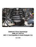
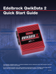
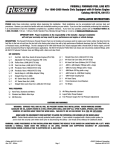
EDELBROCK EFI FUEL PRESSURE REGULATORS
CATALOG #1728, #174041, #174042, #174043
#1729, #174021, #174022, #174023, #174113
INSTALLATION INSTRUCTIONS
®
PLEASE study these instructions completely and thoroughly before installing your new Edelbrock Fuel Pressure Regulator. If you have
any questions or problems, contact our Technical Hotline at: 1-800-416-8628, 7 am - 5 pm Monday-Friday, Pacific Standard Time.
WARNING!
Prior to starting the installation, make sure to eliminate all potential fire hazards as fuel leakage can occur when loosening the fuel
system connections and components.
CAUTION! Installation of this product should be performed by those persons knowledgeable in the repair and modification of automotive
fuel systems. Proper installation is the responsibility of the installer. Improper installation will void the manufacturer’s warranty and may
result in poor performance and engine or vehicle damage. Do not loosen the fuel system connections until relieving pressure as
recommended in your automotive service manual.
1. With the ignition “off” and engine cool, relieve the fuel system pressure.
2. Remove the existing regulator vacuum line, if so equipped.
3. Disconnect the existing regulator fuel lines. Plug the open fuel lines to prevent foreign matter from entering the fuel system.
Remove the existing regulator.
4. Determine the new regulator mounting location. Replace existing fuel lines as necessary for proper fitment. Use existing
bracket holes, if possible. Otherwise, mark and drill mounting bracket holes using the bracket as a template.
5. Install the O-rings and fittings (Fuel fittings NOT included) as shown below.
6. Assemble the bracket and regulator.
7. Install the regulator and bracket assembly in the desired location.
8. Connect and tighten fuel lines to the inlet and outlet, as shown below. Connect manifold vacuum to the vacuum fitting on the
regulator.
9. If installing Model 1729,174021, 174022, 174023 or 174113, install the plug (supplied) or connect a fuel pressure gauge to
the gauge port using a 1/8-27 NPT male thread and thread sealer (not supplied).
10. Check for leaks: Turn ignition to the “Run” position and check all connections for leaks. If any leaks exist, immediately turn
key off and repair before continuing.
11. Start the engine, loosen the jam nut on the top of the regulator, and turn the adjusting screw until the desired fuel rail pressure
is obtained. Tighten the jam nut and re-check the fuel rail pressure.
Fittings Shown:
-10AN to -10AN with O-Ring
Part # 670710 (Qty 2)
& -6AN to -6AN with O-Ring
Part # 670840 (Qty. 1)
Fittings Shown:
-6AN to -6AN with O-Ring
Part # 670840 (Qty. 3)
Adjusting Screw
Adjusting Screw
Gauge Port
or Plug
Vacuum Fitting
Vacuum Fitting
Fuel in -6
Fuel out -6
Fuel in -10
Fuel out -10
Mounting
Bracket
Mounting
Bracket
Fuel Return to Tank -6
Russell fittings
#660350 shown
#1728, 174041, 174042, 174043
Brochure #63-0167
© 2014 Edelbrock LLC
Russell fittings
#660370 & #660350 shown
Fuel Return to Tank -6
(#174113 uses a -8 Fitting #670700)
#1729, 174021, 174022, 174023, 174113
Edelbrock LLC • 2700 California St. • Torrance, CA 90503
Technical Toll-Free Hotline: (800) 416-8628
Rev. 10/7/14 QT