1
F
Installation,Operation
and
MaintenanceManual
for
Wafer-type
BUTTERFLY YALVES
-
-
Installation,Operation
and
Maintenance
Manual
for
Wafer-type
Butterfly Valves
1 . 0 ST O R AG E
On leccipt. check that thc valves and accessorieserreintact. Ensure
that the valve is in a 'crack-open' position so that the clastomer
seatis not under compression.and at the same tirne the disc does
not protrude outside r,alve bodv.
End protectors (stickers) on either side of the valr.e should be
kept in tact and be removed onlv at the time of installation. Direct
exposureto sunlight can deterioratethe elastomer.
The valves should be stored in a covered area. If covered area is
not available. an!. \.rv,ater
proof coverin-s material should be spread
or.erthe valves and the r,alvesshould be kept on a wooden pallet
at least6" above the sround level.
Do not applv tar. paint. grease or an_vother material inside the
l alve or on the shaft as this rvould impair the perfcrrmanceof the
valve.
While transporting the valve from stora-searea to installation site.
it should not be dra-egedon the ground.
F
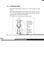
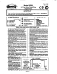
2.0 CONSTRUCTION
AIL Wafer type butterfly valvesare of compactdesignanJ light
weight.
The rubber lined butterfly valvesprovide tight shuroff. 'I'hedisc
seatson to an integrally mouldedelastomerin the body.The disc
is operatedby a shaft driven internally.
The typical valve constructionis shown belo'*,.
VYEATHER SEAL
ACETALBEARING
s@. sETscREw
BODY
TOP SHAFT
DISC
DISC BEARING
BODYLINING
BOTTOM SIIAFT
CIRINC
RETAININGPIN
IMPORTANT
These valves do not require a separateflange gasket while
mounting on to the pipeline. The elastomerseat itself projects
outside the body so as to form a gasket.When the companion
flangeson eithersidearetightened,the elastomergetscompressed
and providesrequiredsealing.
AIL wafer type Butterfly valvescanbe categorisedinto four types
dependingon the type of application.This manual covers the
following types :
-
a.
b.
c.
d.
Slimseal - usedfor generalpurpose.
Chemseal- usedin chemicaland corrosiveservices
Cleanseal- for food & hygienic services
Aquaseal- for air conditioning& refrigerationindustry
3.0 INSTALLATION
a. Handlethe valve with appropriatelifting equipment.Use lifting
lugs/eyebolts only for handling. Prop up the valve temporarily
if necessary.Keep the valve in nearly closed position while
installing.
b. Do not userope or chain throughvalve port. Use the bolt relief
holesat the top of the body for passingthe rope or chain.
c. Carefullycheckthe cleanlinessof the companionflange faces
and cleanif necessary.
d. Centrethe valve suchthat the shaft is in a centreposition.Do
not usevalve asjack to pull the pipe into alignment.
e. Fit the flange bolting on both sidesand tighten. No gasketis
required separately.
f. Ensurethe valve interiors and adjacentpiping are cleanedprior
to tighteningthe joints.
g. Tightenthe bolts, working diagonally to the requiredtorque,
using a torquewrench.
h. Ensurethat the pipline stressesare not transferredon to the
valve as this can result in leakageacrossthe seator difficulty
in operation.
i. In new pipelineswhen weld neck companionflangesare used,
centre each flange bore to the valve bore and run the bolts
through.Tack weld the pipes to the flanges and remove the
boltingsto take out the valve; then finish weld the flangesto
pipe so that the elastomerseatis not damagedby the welding.
j As no separategasketis requiredbetweenthe flanges,flat face
flanges are recommended.In case of valves with EPDM,
Hypalon.Siliconeor Aqua nitrile, it must be ensuredthat the
flange faces are totally free from grease/oil which will swell
the elastomers.
F
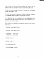
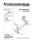
3.1 Do's & Dont's
INSTALLATIONINSTRUCTIONS
--l
,71
Correct Installation
[X
Incorrect Installation
(a) lvlating pipe flanges
shouldbe kept well apan
to allorvfreeaccess
for the
valve.The disk shouldbe
slightlyoff its seatbur not
protrudingto damagethe
disk.
(a) Mating flanges are too
closeto allow accessfor
the valve and the disk in
the wrongposition.
(b) Disk in thesameposition
( s l i g h t l y o p e n . lw h e n
flangebolts are inserted
will ensure that no
distonionofthe seattakes
placeon final tightening.
."ip
-4i[Li |liilt i
-?lq-
(c) Beforeevenlvtightening
theflangeboltsseethatthe
valve is centralisedand
thenifpossible,fully open
with care to ensurethe
d i - s kd o e s n o t f o u l t h e
intemalboreof the pipe.
3.2
Jil-
-gil@-
td#
(b) Disk againis in thewrong
position(closed)andthis
will firstly distortthe seat
on installation and
seconriiycauseexcessive
torquein initial operation.
rc)If the valve is not
centralisedbetweenthe
adjoiningpipeflangesthis
w i l l r e s u l ti n e x c e s s i v e
torque.damageto thedisk
andeventualleakage
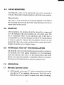
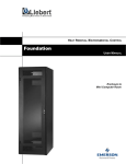
Sequence of Flange Tightening
The sequenceto be followed for bolts tightening while installation
of valve is shown below.
.:.
;;
=--'.\
,z-r'i
, \:
:
-,
.
'..'\/ ./
'J,--<v
':--.
.):>-
/t/
- /.-^-.
5
-
Insert :1bolts near to neck area and tighten the bolts as per the
sequencegir,enin the figure evenly and nor fully tightened.
Check the valve is being concentricto the pipeline and ensure
smoothoperationof valve.
If further bolts are to be tightened.follow the similar sequence
i.e. tightenthe bolts diagonallyand not fully tightened.
Now tighten all the bolts diagonally till the clamping faces of
flangejust touchthe body metal end faces.Over tighteningis not
necessaryand to be avoided.
Thesevalves are suitable for installation betweenpipe flanges
listedbelow:
I. BS 4504- PNIO/DINNDIO
2. BS 4504- PNI6/DIN NDI6
3 . A N S I 8 1 6 . 1- C l a s s1 2 5 l
ANSI B16.5- Class150
4. BSl0 - TableD
5. BSl0 - TableE
6. IS 6418Tables6 to 9
'7.
IS 6392Tablesl0 to 20
I
3.3 Lined Pipes and Heavy Walled pipes should have a
Minimum inside diameterwell clear of Dimension"ZN"
(Refer Figure shown Below) in Disc fullopen positaon.
Dimerrsions
& sizesin mm
Valrc.;i:e
"Z\"
- lirrnn. of
pr(,trudinsdiSc
-50 65
27
.t7
80 100 l2-s 1 5 0 200 250 300 350 .100 450 500 5(X)
6l
83 t07 136 r 8 5 231 280 325 376
176 573
When installingthe valve betweenexistingpipe flanges.the flangesare
requiredto be spreadsufficiently while placingthe valve betweenthem
to preventany damageto the sealingend face which actsas the gasket.
Pipe line is expectedto proviciefor this flexibility.
-
4.0 VALVEMOUNTING
AIL Butterfly valves are bi-directional and can be mounted in
verticalor horizontalor angularpipelineswith shaftin any position.
Slurry Service
The valve is to be mountedon horizontal pipeline with shaft in
the horizontalposition with lower disc edgeopeningin the down
streamside for best results.
5.0 START-UP
After installation,the pipeline shouldbe cleanedby compressed
air or by flushing with water,keepingthe valve fully open.The
use of temporary filters on the upstream side of the disc is
recommendedto avoid any damagecausedby the transportation
of abrasiveparticles. Ensure that the pipeline stressesare not
transferredto the valve as this can distort the seatingand result in
leakagearound the seator higher torque.
6.0 HYDRAULICTEST OF THE INSTALLATION
AIL Butterfly valvesareindividually pressuretestedin our factory.
If a hydraulic test of the piping installationis ro be underraken,
make sure that the valve disc is in the open position and check
thatthevalve materialinstalledis compatiblewith the testmedium.
Testpressurebe limited to the maximum ratedpressure.
7.0 OPERATION
7.1 Manuallyoperatedvalves
(i) AIL Butterfly valvesupto 12" canbe operatedby wrenchand
sizesabove 12" aresuppliedwith gearunit. GearUnit can be
fitted for any size on spqcific requestat the time of ordering.
-
(ii) VALVES WITH FC LEVERAND LATCHARRANGEMENT:
The generalconstructiondetailsof FC lever and latch fitted
on to valve is shown below.
FC LI\JER
t_.{TcH
\O'TCHED I\DICATOR
I
Press the latch upward to releasethe latch from notched
indicator.At pressedcondition operatethe valve.If the pressing
is not done fully while operation,latch will ger damagedby
the notchedindicator.
(iii)VALVES WITH FC LEVER HEAD ARRANGEMENT:
The generalconstructiondetailsof FC leverfitted on to valve
is shown below.
Ht\DLE
FC LE\ER
IIE.\D
NOTCHED
I\DIC,,lTOR
\OSE
Pressthe handledown to releasethe lever headfrom notched
indicator.At pressedcondition operatethe valve.If the pressing
is not done fully while operation,lever head nose will get
damagedby the notched indicator.
(iv) GEARED VALVES : All gearboxeshavean indicatingpointer
on the gear box which shows the angularmovementof the
disc as well as the open/closedpositions.They also have a
positive stop in both the open and closedpositions.
When closing the valve,the handwheelshouldbe turnedonly
up to that position wherethe indicatingpointermatcheswith
the letters"CLOSE" on the gearbox case.This by itself will
ensureproper sealing.There is no need to "slam" the hand
--
wheel till it jams this practice is neither necessarynor
recommended.
Similaris the casewhen openingthe valve.
7.2
Electrically operated valves
Electrical actuatorsare fltted to the gear unit or directly
mounted.
For operationaldetailsconsultthe manufacturer'sinstruction
manual and the appropriatewiring diagram.
Ensurethat electricalconnectionsare given asindicatedin the
wiring diagramfor the specificactuator.
Before making a test run move the disc to an intermediary
positionby meansof the hand wheel.
Startthe motor and seeif the rvorkine direction is correct.
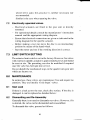
7.3 LIMITSWITCHSETTING
The actuatorlimit switch is setin the facttlry.However.for valves
rvithextensionspindle.actuatoris approximatelypresetandshould
be resetat site. The presettingcan also be modified if required
oncethe valvehasbeenput into service.
Do not disturb the mechanicalstopsin the quarterturn -eearunit
which are factory set.
8.0 MAINTENANCE
ln normal use,thesevalves are tnaintenancefree and requireno
'fit
& forget' valves.
attention.They are literally
8.1
Seat Leak
If the disc is
If thereis a leak acrossthe seat.checkdisc surf-ace.
damaged,it can be replacedas detailedbelou' :
8.2
Dismantling and Re-Assembly
Generallythereis no needto dismantleour valve:;.However,if it
is desired,the valve can be dismantledand reassembled.
To dismantlethe valve, proceedas follows.
t0
I
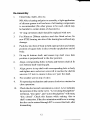
8.2.1(a)
50-300mm SL|MSEAL,
CHEMSEAL
& CLEANSEAL
BUTTERFLY
VALVES
The constructionof this group is shownin the following diagram:
WEATIIER. SEAL
ACtsTALBEARING
SOC.SETSCTEW
BODY
TOP SIIAFT
DISIC
DITICBEARTNG
BODYIINING
BOTTOMSIIAFT
ORING
R.ETAININGPIN
Dismantling
l.
Removethe gearunit or actuatorif fitted. The wrenchmay
be left in position on wrench operatedvalves.
2.
Removethe socketset screw and pull out top shaft.
3.
Removethe bottom shaft-retainingpin.
4.
Insert a long drift through rhe rop shaft hole and drift out
the bottom shaft.
5.
Pull out the disc.
ll
--
Re-Assembly
1.
Cleanbody, shafts,disc etc.
2.
NB: After cleaningand prior to assembly,a light application
of siliconegreaseto all surfacesof all mating components
is recommended(No other greaseto be used,which may
be harmful to certain kinds of elastomers).
'O'ring on bottom shaft shouldbe replacedwith new.
3.
For 50mm to 200mm stainlesssteeldisc fitted valves,fix
new PTFE bearing into disc if the bearing has sufferedany
damage.
4.
Pushdisc into bore of body in fully openposition andensure
positionof squarehole in disc towardstop platform end of
body.
5.
Fit top & bottom shaft, and ensuretop shaft cross hole
position is perpendicualrto the disc position.
6.
Align correspondingholes in body and bottom shaft & fit
new bottom shaft-retainingpin.
7.
Align groove in top shaft with correspondinghole in body
and tighten new socketset screwtill it touchesthe shaft&
unscrew ll2 tum to ensureit doesnot Jam' the shaft.
8.
Fix weathersealon top of valve.
9.
Fit operatingmechanismandensureclockwiserotationfor
closeoperation.
10. Checkthe disc/wrenchorientationis correct.Lever indicates
"Lever alongthe pipeline"
the positionof disc in the valve.
"across
"disc open", and
the pipeline" will mean,
will mean,
"disc closed". Check this feature while making 'disc to
shaft' connection.If the disc orientationwith lever is wrong,
the disc canbe rotatedthrouqh 90" to correct the fault, after
dismantlins.
l2
I
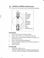
(b)
350-600mmSLIMSEALButterftyVatves
The construcitonof this group is shownin the following diagram.:
BODY
soc. SETSCREW
BODYBEARING
BODYLINING
TOP SIIAFT
DIIIC
DISC BEARING
BOTTOM SIIAFT
RETAININGPIN
PLUG
NUT
BOTTOM @VERPI.AIE
Dismantling
l.
2.
3.
4.
Removethe gearunit or actuatorif fitted.
Remove the socket set screw and pull out top shaft
Remove the screwsand remove bottom cover plate, lock
plate, plug & ring nut.
Remove the bottom shaft-retainingpin.
5.
Insert a long drift through the top shaft hole and drift out
the bottom shaft.
6.
Pull out the disc.
Re-Assembly
l.
Cleanbody, shafts,disc etc.
NB: After cleaningandprior to assembly,a light application
of silicone greaseto all surfacesof all mating components
l3
-
2.
3.
4.
5.
6.
1.
8.
9.
8.2.3(c)
is recommended(No other greaseto be used.r.r'hichmay
be harmful to certainkinds of elastomers).
Pushdisc into boreof body in fully openpositionandensure
positionof squarehole in disc towardstop platform end of
body.
Fit top & bottom shaft. and ensure top shaft cross hole
positionis perpendicular
to the disc position.
Align correspondingholes in body and bottom shaft & fit
new retainingpin.
Align groove in top shaft with correspondinghole in body
and tighten new socketset screwtill it touchesthe shaft&
unscrewl/2 turn.
Fix lock plate with gasketor 'o' ring to bottom platform of
body.
Lock the bottom shafl with plug and ring nut adjusting
suitablyto avoid seatleak.
Fix the bottom cover plate '*'ith 'o' ring or -qasketto the
platform of body.
Fit operatingmechanismand ensureclockwiserotationfor
closeoperation.
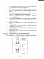
50-300mmAquasealButterflyValves
Theconstructionof this model is sho'*.nin the followins diasram:
t4
-
2.
-3.
4.
5.
6.
l.
8.
9.
8.2.3 (c)
is recommended(No other greaseto be used.which may
be harmful to certainkinds of elastomers).
Pushdisc into boreof body in fully openpositionandensure
positionof squarehole in disc towardstop platform end of
body.
Fit top & bottom shaft. and ensuretop shaft cross hole
positionis perpendicular
to the disc position.
Align correspondingholes in body and bottom shaft & fit
new retainingpin.
Align groove in top shaft w.ithcorrespondinghole in body
and tighten new socketset screwtill it touchesthe shaft&
unscrew l/2 turn.
Fix lock plate with gasketor 'o' ring to bottom platform of
body.
Lock the bottom shafi with plu-eand rin-enut adjusting
suitably'toavoid seatleak.
Fix the bottom cover plate with 'o' rin-eor ,gasketto the
platform of body.
Fit operatingmechanismandensureclockwiserotationfor
closeoperation.
50-300mm Aquaseal Butterfly Valves
Theconstructionof this model is shownin the following diagram:
ROSS HOI-E
WTmSilL
AmlBImc
rcPSffi
MDY
AODY UNC
Dts
BOTTOMSffi
omG
HMGPN
TMDHOT
t4
a
Dismantling
l.
Removeoperatingmechanismcomplete
2.
Removebottom shaft-retainingpin & puli bottom shaftby
using tappedhole at the bottom.
3.
Pull out top shaft & acetalbearingby using crosshole.
4.
After removing two shaftsthe disc can be pushedout from
the bod1.'.
Re-Assembly
l.
)
Cleanbody'.shafts.disc etc.
NB: Atier cleaningandprior to assembly.a light application
of silicone-qrease
to all surfacesof all mating components
is recommended(No other greaseto be used.which may
be harmful to certainkinds of elastomers).
'O'
ring on bottom shaft & acetal bearing fbr top shafi
shouldbe replacedwith new.
-)-
Pushdisc into boreof bodyin fully openpositionandensure
position of squarehole in disc towardstop platform end of
body.
4.
Pushthe bottom shaft into body and disc shaftholes.
5.
Ali_encorrespondingholes in body and bottom shaft & fit
nerr retainingpin.
6.
Pushthe top shaftthrou-shbody shafthole to locarein disc.
7.
Fix new acetalbearingat the top of body till it touchesthe
top shaft shoulder.
8.
Fix weathersealon the top of valve.
9.
Fix operatingmechanismandensureclockwiserotationfor
closeoperation.
1 0 . Check the disc / wrench orientationis correct. Lever
indicatesthe positionof disc in the valve. "Lever alongthe
pipeline" will mean,"disc open",and "acrossthe pipeline"
will mean."discclosed".Checkthis featurewhile makins
l5
-
'disc to shaft' connection.If the disc orientationwith lever
is wrong, the disc can be rotated through 900to correct the
fault.
AFTER ASSEMBLING ANY SLIMSEAL, CHEMSEAL,
CLEANSEAL OR AQUASEAL VALVE, THE FOLLOWING
PRECAUTIONSTO BE FOLLOWED TO ENSURE TROUBLE FREE
PERFORMANCE.
GENERAL PRECAUTIONS
l. If any further cleaning is necessarythis should be done with
diluted detergentfollowed by water and should not be with a
hydrocarbonor similar solvent.
2. Check completeoperationof valve and if necessaryadjust the
'open' and'shut' positionsofgearboxes and actuatorsto ensure
correct operation.
3. Pressuretestthe valve beforeputting it back to work' If in doubt
aboutthe testprocedure,pleasereferBS : 5155latestamendment.
4. Do not exposeelastomerseatsto sunlightor ozonefor extended
periods(In caseof black nitrile liner, its contactwith ozoneshould
be totally avoided).
5. Foreignmaterial in the butterfly valve can damageelastomerseat
when operated.Ensure valve interiors and adjacent piping are
thoroughlycleanedprior to installation.
6. Ensure the valves are not subjectedto pressuresabove rated
pressuresof the valves(Black nitrile - 16 bar; White nitrile - 14
bar; Hypalon/Viton- 12bar EPDM, Silicone - 6 bar: Aquaseal10bar).
7. Ensure end faces are suitably protected by end protectors to
preventdamageto disc and body lining while in storage.
8. If pipelinesarebeingpurgedprior to commissioning,this should
be done with the valves in the fully open position. Care to be
takento ensurethat the purging pressuredoesnot exceedthe test
pressureof the valve.
l6