1
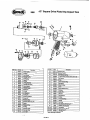
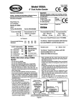
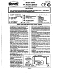
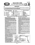
-
Form # Z470
Date 1- W A
Model 5550
C? @
1/2" Sq. Drive Pistol Grip
. Impact Tool
IMPORTANT
1
Read these instructions carefully before installing, operating, servicing or repairingthis
tool. Keep these instructions in a safe accessible place.
I
SAFETY MESSAGES
1
1A
Always Read Instructions
Using PowerTwls
PeoonalSafetyEqucment
Use - Safety Glasses
Use Safety Gloves
Use Safety Boots
Use - Breathing Masks
Use Ear Protectors
-
-
-
YES
1
WARNING
@
Always Wear Safety Goggles
@
Wear Hearingprotection
A
Avoid Prolonged Exposure
To Vibration
1
II
Operator Instructions
includes:
Safety R u k
Foreseen Use
Work Stations
Putting Into Service
Operating
Dismantling and Assembly.
Safety rules when using a 5550 ImpactTool
- Use only impactsockets and extensions,universaljointe,
etc., rated as being suitable for use with impact tools.
- Prcibqed exposure to vibration may cause injury.
.- ReadaBjnstrucfionsbeforetKhgltfetoot.AIoperatorsmust
beMytrainedinitsuseandawareoftiesesafetyrules.
- Do not exceed the maximum working air pressure.
- Use personal protectionequipment & recommerKled- WcofnpressedsironlyattÈrecornnerxledconcflions
practicaltoremovetoolfromsewh, thanshutofftheair
supply to the too! and write or have written a warning
note and attach it to the tod.
- I f tool is to be used wtt) a baiancer or other suspension
device,ensure that the too)is firmly attached to the
suspension/supportdevice.
- When operating the tori, always keep the body and
the handsaway from the woriang attachment
Theiwlisnoteiectri
insulated.Neveruseftatoolif
there is any chance o
into contact w ' h li
electricity.
- Always when using the too[,adopt a firm footing and/or
posHion and p the tool sufficiently arty to overcome
any reaction ces that may result from the tool doing
work. Do not ororgrip.
- Use only correct spare parts for maintenanceand repair.
Do not improvise or make temporary repairs- Major
servicing and repairs should only be carried out by
cany
e
- personstrainedtodoso.
Do not lock,tape, wire, etc. the 'On/Off valve in "On'
position.'me tfvotfte trigger/tever, etc. must ahvays be free
to return to lhe "Off"positron when released.
other person or material or substance that could be
contaminatedby oil droplets.When first lubricating a tool
or if the tool exhaust has a high oil content, do not allow
the exhaust air to come near very hot surfaces or flames.
Never lay the too! down until the working attachment has
stopped-moving- When the tool is not in use, shut off the air supply and
press Ihrotfle frioaerfiever to drain the supply line. I f the
tool is not to be used for a periodof time, first lubricate,
dsconnectfroman-supplyandstoreinadryaverageroom
temperature environment
- If the fool is passed from one user to a new or inexperienced user. make sure these instructionsare available to
be passed withthetool.
- Do not remove any manufacturer fitted safety devices
where fitted, i.e., wheel guards, safety trigger. speed
go-,
etcWherever p-e,
secure workpiece with clamps, a vise,
etc.tomate itngtd soçtdoesnomoveduringthe work
operation.Keep good balance at aU times. Do not stretch
or overreach.
- Try to match the tool to (he work operation. Do not use a
tod that is too light or heavy for the work operation. If in
doubt, seek advice.
in generalterms, this tool is not suitabie for underwater
use or use inexplosive envirmrnente-seek advice from
manufacturer.
-
- immed"lately
If the tool appears to malfunction, remove from use
and arrange for service and -r.
ti it is not
KExw.
requirements when instaihng, usingor maintainingthe tool.
- Take care W#eexhaust air does not point towante any
shutofftheairsupplytoVnetootandpressthe
Obefore
n / Wfitting,
valve to exhaust the air from the feed hose
removing or adjusting the working attachmentfittedtothetool.
- shutoffdeucehasbeenfittedtothe
Beforeusinothatool.makesurethata .
-
- Tvtomakesurethattheworkareaisdeartoenablethe
work task to be performed safely. If practical and
-
possible, b'y to ctear unnecessary obstructions before
starting work.
Always use air hose and couplings with minimum working pressure ratings at least 1 1/2 times the maximum
working pressure rating of the tooL
supply tine and the position is known
andeasilyaccessiblesothattheair
supply to thetoolcanbeshutoff inan
emergency.
- CheckhoseandfitSngsreoulartyfcfwear.
- Takecareagainstentanglementofthe
movtrgpartedttwtoolwithdoÈwg,hair
To Maintain FteconnnenitKt
fes,deaningrags.rings,jewafry.watrfres.
bracelets,ete.'nrecotAJcauseftebody
orpartsoftktbodytobedrawnfcwaids
axiricortactwflhihemovingpartsofSw
toolandcouldbevarydangerous.
- itisexpectedthatuserswiladoptsafe
working practices and observe all
local, regional or country legal
Recommended Air Supply System
Pager401
Figure 1
Foreseen Use Of The Tool - 5550
The Impact tool is designed for the tightening and loosening of threaded fastener within the range as specified by the manufacturer. It
should only be used inconjunction with suitable impact type 112" square female drive nut running sockets. Only use sockets which are of
Die Impact type.
It is allowed to use suitable extensionbars, universal joints and socket adaptors betweenthe square output drive of the impact tool and
the female square drive of the socket.
Do not use the tool for any other purpose than that specified without consulting the manufacturer or the manufacturer's authorized
supplier. To do so may be dangerous.
Never use an impact tool as a hammerto dislodge or straightencross threaded fasteners. Never attempt to modifythe tool for other uses
and never modify the tool for even its recommended use as a nutrunner.
Work Stations
The tool should only be usedasa handheld, handoperated toot.# Isalways ~~~OInmended
that the tool is usedwhen standingon a solid
floor. It can be used in other positions, but before any such use, the operator must be in a secure position having a firm grip and footing
and be aware that when loosening fasteners the tool can move quite quickly away from the fastener being undone. An allowance must
always be made for this rearward movement so as to avoid the possibilityof handlarmhmdyentrapment.
Putting Into Service
Air Supply
Use a clean lubricatedair supply that will give a measuredair pressure at the tool of 90 PSIQ (6.2 bar) when the tool is runningwith the
triggerhever fully depressed. Use recommendedhose size and length. Itis recommendedthat the tool is connected to the air suoolv as
shown In figure 1. Do not connect the tool to the air line system without incorporatingan easy to reach andoperate air shut off vake.The
air supply should be lubricated. It Is strongly recommendedthat an air filter, regulator, lubricator (FRL) is used as shown in Fgiure 1 as
thls will supply dean, lubricated air at the correct pressure to the tool. Details of such equipment can beobtainedfrom your supplier. If
such equipmentis not used, then the tool shouldbe lubricatedby shutting offthe air supply to the tool, depressurizingthe line by pressing
the trigger on the tool. Disconnect the air line and pour into the hose adaptor a teaspoonful (5ml) of a suitable pneumatic motor
lubricatingoil preferably incorporating a rust inhibitor. Reconnect tool to air supply and run tool slowly for a few seconds to allow air to
circulate the oil. tf tool Is used frequently, lubricateon daily basis and If tool starts to slow or lose power.
It is recommended that joint tightness of the threaded fastener assembly be checked with a toque wench.
It is recommendedthat the air pressure at the tool while the tool is running is 90 PSI/6.2 bar.
Operating
The output of the impact tool in prime working condition is governedby mainly three factors:
a) the Input air pressure;
b) the time the impact tool is operated on the joint. Normaltime for joints of average tension requirement3 to 5 seconds;
c) the setting of the air regulator for a given joint at a given pressure operated for a given time.
The air regulator (14) can be used to regulate the output of the impact tool if no other means of control is available. It is strongly
recommendedthat an external pressure regulator. Ideallyas part of a filterlregulator~lubricator
(FRL), is usedto control air inlet pressure
so that the pressure can be set to help control the tension requiredto be applied to the threaded fastener joint.
There is no consistent, reliable toque adjustment on an Impact tool of thls type. However, the air regulator can be used to adjust toque
to the approximatetightness of a known threaded joint To set the tool to the desired toque, select a nut or screw of known tightness of
the same size, thread pitch and thread condition as those on the job. Turn air regulator to low position, apply tool to nut and gradually
increase power (turn regulator to admit more aio until nut moves slightly In the direction it was originally set. The tool is now set to
duplicate that tightness, note regulator setting for future use. When tightening nuts not requiring critical toque values, run nut up flush
and then tighten an additional onequarter to one-half tum (slight additionalturning is necessary if gaskets are being clamped). For
additional power needed on disassemblywork, turn regulatorto its fully open posWton. This impact tool is rated a 1/2" bolt size.
Ratingmust be downgradedfor springU bolts, tie bolts, long cap screws, doubledepth nuts, badlyrustedconditions and spring fasteners
as they absoib much of the impact power. When possible, clamp or wedge the bolt to prevent springback.
Soak rusted nuts in penetratingoil and break rust seal before removing with impact tool. If nut does not start to move in three to five
Seconds use a larger size Impacttool. Do not use Impact tool beyond rated capacity as this will drastically reduce tool life.
NOTE: Actual toque on a fastener Is directly relatedto joint hardness, too) speed, conditionof socket and the time the tool is allowed to
impact.
Use the simplestpossible tool-to-socket hook up. Every connectionabsorbs energy and reduces power.
The direction of rotationof this tool is controlled by the throttle lever. Be sure that it is known which side of the lever has to be pressed to
give the required directionof rotation before applying the impacttool to the joint to be fastened or loosened.
For best results:
1) Always use the correct size impact type socket.
2) Use extra deep sockets in place of extension bars where possible.
3) Do not use oversized, worn or cracked sockets.
4) Hold the tool so the socket fits squarely on the fastener. Hold the tool firmly, but not too tightly, pressing slightly forward.
Dismantling & Assembly Instructions
DiSC~nnecttool from air supply.
Remove protectiveboot (46). Remove oil plug (22) and drain oil into a suitable container. Grip motor housing (1) in a vise fitted with soft
jaws and remove hose adaptor (10) together with spring (9), O-ring retainer (8), valve stem (6) fitted with O-ring (7). Drive out spring pin
(15) and carefully pull out regulator (14) together with O-ring (13). O-ring (13) may be pried off of regulator (14) but do not attempt to
remove the small ball.
Driveout spring pin (12) and remove trigger (11). Inserta small diameter rod into the hose adaptor hole and push out throttle pushpin (4)
together with O-ring (5) via the trigger pin slot.
Unscrew retainerplug (21) and remove spring (20) and reverse valve stop pin (19). Reversevalve (18) may now be pushedout of motor
housing (1). Do not attempt to remove the brass reverse valve bushing from the motor housing (1).
Remove2 screws (17) and exhaust deflector (16). Remove4 cap screws with washers (45) and removeend cap (44) and gasket (43). By
gently tapping the square end of anvil (29) the complete hammer assembly and motor assembly may be removedfrom the rear end of
motor housing (1). Oil seal (2) may be hooked out of, and anvil bushing (3) pressed out of motor housing (1). Pull apart the motor and
hammer assemblies. Remove guide pin (38) and pull off rear end plate (34) and front end plate (42) from rotor (35) and remove 6 rotor
blades (36) and cylinder (37) notingits orientationwith the front end platefor correct reassembly. Bearing (33) may be tapped out of rear
end plate (32) and bearing (40) from front end plate (42) with a suitable punch and oil seal (39) hooked out of front end plate (42).
Remove O-ring (41) from end plate442). Removeanvil spacer (30) and pull out anvil (29) to separate hammer cage (a), cam ball pilot
(24). ball (251, hammer cam (26). s
p
m (28) and 2 pins (27). Note that on reassembly, the chamfer on the bore of anvil spacer faces
towards hammer cage (23). Socket retaining ring (32) and O-ring (31) may be removedfrom anvil (29).
Page No 2
5550
112" Square Drive Pistol Grip Impact Tool
~ e fNO.
.
26
27
28
29
30
31
Page
1
Pan NO.
505177
505178
505179
505380
505181
66673
Description
Hammer Cam
Hammer Pin (2)'
Cam Release Spring
Std. Anvil Assy. (includes items 31 & 32)
Anvil Spacer
0-Rim
Reassembly
Ctona>conxunenipartsamiexanftÈfc)rwearand<Èac^etc,Èxf~as[~cessa~yLeÈklnpaificularkrvf~r
0-rt^andseakwearmrotorUadesarriwearandctactaonanvtt(29)parBc^riyhhan^ofttiswtiafedrtw-l^^~(~),
cam(W),cambaflp^<24)arelhamnerpins(27).Makesurethatthefecesof mdplates(34)d (42)9^alxfttt^~i11IUerWare
Batandfreeofbuns.LaponaMfimgiç^(tfatwasivepaper#necessary.Useone(nanubcurerorauHwnz^ti~m~e~m
Ugt^~talpartsw^asuitatepneumatetoolhibrtcatingoila^reassembtein~rev>af~Older.
Oncompletingtheassemfify,matesuretheanvilisfreetorotateandIhe(everandregulatoroperatefreaty.Removeoilplug(22)and
p~hone<x~ue(28cc)dastxtal^??10orSAE^gif^oLDoiKftoveiffllasttiteWresiftinared^d~~rdhW.
Pi>urapprox.5trtoiagood(iu~poewaBctoolnKitorht>ricatioaoB(pf^~ma~amt~w~&Mm
thetriggerdepressetLCornedb~l~asuilabteair~a>KJopec^etodskn^forafewse^^&~hd~ti&ted&
for operation requtred. Refer to section^QpeiaBng".
operationspecification
3.5 dm (25 sc(m)
Air Consumption
4eo It lb. (624Nm)
-Ttxque
W0tking-W
Air MetThread
ft. Q 6
(1
1/4'18MPT
50-
1
-nLength
7.5" (190mm)
at90P8H3(62bd
ProductType
112" Sq. Drive Pistol Grip
ImpactTool
Manufacturer/SuppT1~r
SiouxTools Inc.
2901 Floyd Boulevard
P.O. Box 507
Sioux City,IA 51102
Serial No.
U.S.A.
Tel No. 712-252-0525
Product Netweight
5.3
Ibs
Kg
1I
1 RecommendedHose Bore 1
1
Size - Minimum
1
5/16
Ins
8
W
M
I
1
Fax No. 712-252-4267
1
1
1
I
Recornmendod UseOl
~aiancerOrSupport
NO
SAFETYMESSAGES
Use-SafetyUse-SafetyGlows
Use-SafetyUse - B r e a m Masks
Usa -Ear Protectors
YES
10 M
Sound Power Level 102.0 dB(A)
bar
90
PSI
bar
90
PSI
A
@
Test Method: Tested in accordance with Pneurop
1 test code PN8NTCI and IS0 Standard 3744
WARNING
assar-
Vibration Level
Less than 2.7 Meters1Set2
Ww Safety
Gooctes
--
Test Method:
Tested in accordancewith ISO
AtiÈay
=
Hose Length
30 Ft
Noise Level: Sound Pressure Level 91-0 dB(A)
Air Pressure
RecornrnendedWorking 6.2
Maximum
6.2
Recommended Max.
A)
WMrHatnig-
A
A u w PrcilonsedExposure
standards8662Parts1&7
Bwx&b-i
-
Declaration of Conformity
SiouxToots Inc.
2901 Floyd Boulevard, P.O. Box 507, Sioux City, Iowa 51102
declareunderoursoleresponsibBityVattheproduct
M o d e l 5550 Sq. Dr. Pistol Grip ImpactTool, Serial Number
towhichÈusdeclarationrotatesiskiconfonrttvwiththefctowingstctf)da@s)orottÈer--
EN792 (Draft), EN292 Parts 1 & 2, ISO 8662 Parts 1 & 7, Pneurop PN8MTC1
89/39
as dB)byglfiffiaEECS44/EI,EC
Directives
fallowingttwprovisionsof
-------------<
bertson (V.PfG.M.)
------+--------
N-aidsignBtureoreçÈaten(niaikhgdauthorizedpais
Page No 4
a