1
MIMS Machinery Movers mimsriggers.com
"|
iii
BiliI
MIMS SERVICE
Machinery Movers mimsriggers.com
MANUAL
u
U
UPPER LEyEF{
"I<AGE REj|JRN
!`
i...``.
|
MANUAL
SERVICE Movers mimsriggers.com
MIMS Machinery
A
SUPPLEMENTAL TOWMOTORQUE ADJUSTMENTS
CREEPER PEDAL ADJUSTMENT: (EARLY MODELS WITH ROUDun CREEPER PEDAL) (See Page
1.)
Creeper pedal travel should be set so that the
pedal contacts the stop bolt (1/32 inch additional
travel after the valveplunger is all the way into the
valve body). Adjust creeper pedal by lengthening
or shortening the adjustable yoke at the valve.
CREEPER PEDAL ADJUSTMENT: (RATE MODELS
WITII STANDARD CLUTCH CREEPER PEDAL)
To adjust this t]xpe of creeper pedal linkage proceed as follows: Disconnect the upper lever from
the creeper lever support, mounted on the transmission, by removing the cotter pin and slipping
the upper lever off the creeper lever support.
IJOOSenthe lOCkingPlng inthe end Of the Cross Shaft.
1
The springloaded lowercontrol lever will then rotate the cam plate until both creeper control lever
pins contact the left edge of the holes in the cam
plate. Tighten the locking plug approximately 10
foot pounds of torque maldng sure the cross shaft
does not rotate in the cam plate.
Move the creeper plunger to its fully extended
position and place the creeper pedal against the
pedal stop.
Withthe creeperplunger extended and the creeper
pedal against the stop) reinstall the upper lever on
the creeper lever support. The hole in the upper
lever should be aligned with the pin in the lower
lever. To make this alignmentl loosen ball joint
jam nuts, then turn ball joint and upper leverl as
an assembly} in or out as necessary to align pin
and hole. After adjustmentis set, tightenball joint
jam nuts and install washers and cotter pins as
necessary.
1. If the clutch does not completely disengage
with the creeper pedal positioned between one or
two inches from the floor board) the ball joint or
adjustableyoke maybe adjustedto have the creeper
plunger positioned somewhat into the valve body
with the pedal fully released. The plunger should
not be positic)ned into the valve body sufficiently as
to cause an increase in the shift eycle time or the
clutches to slip. The position of the plunger that
would cause achange in the shift cycle time varies
with each valve body due to the internal'cored oil
passages in the valve body.
2. If the pedal position for creeping the truck is
not the same in forward and reverse gearl the cam
plate may be rotated slightly on the cross Shaft tO
compensate for the difference in travel ofthe clutch
linkage. If the pedal position is lower in forward
gear than in reverse, rotate the cam plate on the
cross shaft in a clockwise direction (viewed from
the left side of truck). Ifthe pedalpositionis higher
in forward gear than in reverse gear, rotate the
cam pla.te on the cross shaft in a countercloctw7iSe
direction. This adjustment may be required with
each rebuild of the transmission that affects the
amount of travel of the clutch linkage.
I
It is necessarythat the movement of the creeper
plunger closely follow the movement of the creeper.
pedal due to the nature of this control mechanism.
A binding or sticking condition in the linkage that
results in an abrupt movementof the plunger in the
valve bodyl causes the truck to lurch and gives
difficulty in controlling the truck speed during
creeping. Tlle linkage Should be lubricated with
SAP 30 engine oil at eachpivotjointduring assembly
and none of the linkage should bepainted. The linkage return spring preloads the linkage to take up
the initial clearances at each pivot point, and any
increase in clearance due to wear.
NOTE
On Models 540, 600,
670 and 680-P,follow
the same adjustment procedure except when
aligning the hole in the upper lever and the
pin in the lower lever'disconnect the adjustable yokeat the brake pedal. Turn yoke and
lever as an assemblyin or out as necessary
to align pin and hole.
iI
After the initial linkage adjustments have been
made, it may be necessary to make further adjustments to the linkage after the truckhas been driven
for the first time.
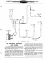
CREEPER PEDAL AND LINKAGE
(LATE MODELS)
The following information contained in these
supplement pa.gee refers to the adjustments of this
whew style" creeper pedal linkage.
Variations in
operation between "early modelw linkage and Mlate
modelw linkage is given under the title uHow to
Creep in Tight Spots".
MIMS Machinery
Movers mimsriggers.com
MANUAL
SERVICE
This new style linkage is quite sensitive in its
creeper pedal actions, therefore, accurate adjustments are required for best efficiency and operation
of the truck during "creepingw.
Identification between "early" and nlate" model
linkage can bc distinguished as follows: Early
models have a round button-type creeper pedal
while the late models use apedal similar to a standard transmission clutch pedal.
U
HOW TO 'ICREEP" IN TIGHT SPOTS"
(LATE MODELS)
Procedures for creepihg in tight spots areessentially the same as those used in the "earlymodels"
except that extremely easier creeper pedal action
is obtained through the newly designed linkage. In
effect, the creeper pedal linkage is given a hydraulic
and mechanical assist by the shift cylinder, cross
shaft and cam plate. The amount of creeper pedal
effort varies only with the force exerted by the
creeperpedal returnspring. This enables the operator to "ride" the creeper pedal for less effort
when inching. It is not necessary to "pump" the
creeper pedal for inclling) it iS Only necessary tO
move it slightlyup and down. After a few trips the
operator can readily determine the amount of pedal
travel necessary for inching.
u
u
MANUAL
SERVICE Movers
MIMS Machinery
mimsriggers.com
EI
TOWJVIOTOROuI
SERVICE MANUAL
The Service Manual is divided into sections as listed in the Table of Cc)ntents.
It contains service and repair instructions for Towmotorque Transmissions a.s used
on Towmotor Models 540, 600) 670 and 680-P.
The service and repair infc)rmation contained in tlliS manual covers the trams-
missions being currently produced and sold by the Towmotor Corporation.
1
When ordering replacement parts be sure to use genuine Towmotor Specified
Replacement Parts.
Use of substitute parts results in lower operating efficiency
of the lift truck.
SERVICE DEPARTMENT
TOWMOTOR CORPORATION
1
MIMS SERVICE
Machinery Movers MANUAL
mimsriggers.com
U
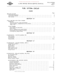
TABLE OF CONTENTS
Page
IIOW
TODRIVEWITHTOWMOTORQUE,.......................
DESCFIIPTION
...............
....I..''.'.....
1
.'.........
ShiftingCycleTime''..................-................
CreeperPedalOperation..................................
BrakingwithTowmoTorque................................
TOWMOTORQUE
OILSYSTEM................-.......I......
Description'.I.........................-.-......'..'..
OilChecking)DrainingandFilling
OilPressureCheck
...........................
. . . ....
ClutchCooling Check...... I
TOWMOTORQUE ADJ USTMENTS
CreeperPedal Adjustment... I
Control Lever Adjustment... I
Clutch Adjustment and Operation Check........
TOWMOTORQUE
TROUBLE
SHOOTING.........................
PrimaryChecks...............'''.I....................
TroubleConditionsandCheckPoints
REPAm
INSTRUCTIONS
.......
.'..I....................
..I.........................
TowmoToI.queReplacement................................
i; 6
10
Disassembly..,.........,.............................
10
Assembly.......................................,...,
16
OilPump.................
17
Duplex Clutch and Shifting Linkage
18
18
ShiftOperating Cylinder.......
ContI.OIVa-lve
.............
|
__
2l
|
MANUAL
SERVICE Movers mimsriggers.com
MIMS Machinery
HOW TO DRIVE WITH TOWMOTOROuE
EiI
I.
CFiEEPER
SHIFT
PEDAL
LEVER
Position shift lever in neutI.al and Start engine.
Positioning shift lever in neutral operates a safety
switch which closes a circuit to the sta.rting motor
and permits operator to start engine.
3. Drive Towmotor. Once Towmotor is in motion, the driver need only step on the gas pedal for
speed control - a-nd move control lever if he wants
to change direction.
2.
shift
ward
lever
4. To stop. Release gaspedalandsteponbrakes
to stop Towmotor. It is not necessarytomove contI.Ol lever into neutral or step on creeperpedal.
Shift control lever and push ga,s pedal. Push
lever forward to go forward. Pull leverbackfor reverse. Push gas pedal and move shift
at the same time.
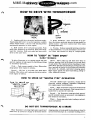
HOW TO "CREEP" lN UTICHT SPOTSw
1
(EARLY MODELS)
To drive Towmotor at a creeping speed and still
Third... Move pedal up and down from floor to
operate engines at high speed for fast liftingJ tilting
halfway position and at the same time press down
Or accessory OPeI.atiOn...
on gas pedal. The repeatedaction of pushing creeper
pedal down quickly and releasing it slowlywill cause
First... Push creeper pedal to floor. Thisaction
short periods of partial drive motion and Towmotor
stops power from engine to wheels.
will move at a smooth, controlled creeping speed.
Second... Lift foot to let pedal come back about
High engine speed will allow fast lifting} tilting or
halfway. This action will causepartialdrive motion
other hydraulic actions.
from engine to wheels.
HOW TO SPEED uP 'lSHunLE TYPE" OPERATION
For fast "shuttle type, ' opeI.atiOn, Change travel
direction without stopping Towmotor completely
(low engine speed recommended).
First... When Towmotor is twoor threefeetfrom
load, pull shift leverbacloward. This leaves driver,s
hands free to operate lift controls.
Second... Let Towmotor coastupto load, operating lift control lever.S aS neCeSSar.y and StePPingOn
foot brakes if necessary.
|
Third... Press gas pedalwhen loadingor unloading is completed.
DO NOT USE TOWMOTOROuE AS A BRAKE
lhthen Towmotor is moving (high engine speed) and
shift leveI` iS moved for Change Of direction before
stopping?step onbrakepedalto slow downor stop. Do
not use Towmotorque as a constant braking power.
MIMS SERVICE
Machinery Movers MANUAL
mimsriggers.com
u
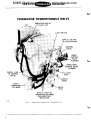
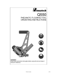
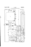
TOWMOTOR TOWMOTOROUE DRIVE
u
SUPPLY LINES TO
OPERATING CYLINDER
FOR DIRECTION
SELECTION
Fie.
1.
To-oTorque
TretlsmlSSiOn
-
A.Bembled
View
L
SERVICE Movers
MANUAL
MIMS Machinery
mimsriggers.com
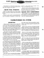
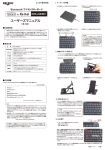
DESCRIPTION
Ei]
FORWAF]D
AIR
COOLING
DIRECTIONAL-CLUTCH
FAN SHROUD
REVERSE
OIRECTIONAL-CLUTCH
TORQUE
CONVERTER
COOLING
AIR
REVERSE
OUTLET
DRIVING
GEAR
FORWARD DRIVINC
GEAR
CREEP CONTROL
VALVE FILuNGER
FOFtWARD IDLER
GEAR
DIRECTIONAL CONTROL
VALVE PLUNGER
OUTPUT GEAR
1
OUTPUT SHAFT
CONNECTION
Flo.
2.
To-oTc,rc(ue
TowmoTorque is designed to provide hydI.a.uliCally controlled power... to eliminate gear shifting
and clutching delays... and to provide effortless
driver control.
The TowmoTorque drive is a heavy duty> arrand
oil cooled hydraulic torque converter type transmission. The principle operating parts are a hydraulic torque converter, a duplex directional clutch
for forward and reverse travel, and a constantmesh, drop-down t]pe gear train tha.t requires no
shifting. DI.iVing torque iS transmitted Smoothly
and efficiently from the engine through the converter
to the drive wheels for either forward or. reverse
movement. Control of forward or reverse direction
is accomplished by a flip c)I the control lever which
is positioned at the steering wheel.
J|
The hydraulic torque converter is a combing.lion
fluid coupling and torque converter of the singlestnge, thI.ee-element type. The three elements are
the impel|er, the turbine| and the statoI.. The impeller is driven by the engine flywheel, the turbine
drives the clutch, and the statorpl.ovides the ability
to multiply torque.
C:uta-E\y
The duplex directional clutch consists of aclutch
f1]rvheel driven by the converter, a double-faced
pressure plate, and forward and reverse clutch
plates. These parts) plus operating links}pins}etc.
are enclosed in a. clutch cover. Clutch plates are
coned to assure rapid disengagement.
The gear train is a drop-down type consisting of
SPLIT t]Pe gears Which are in COnStant mesh. Gear
shafts are supported by heavy-duty ball and/or
roller bearings.
The converter, clutch, and gear train are housed
in two individual caces bolted together. The conveI.t-
or case houses the hydraulic torque converter and
the transmission case houses theduplexclutch and
the gear train.
SHIFTING CYCLE TIAAE
The shifting cycle, to either forward or reverse,
should be accomplished ln 3/4 to 1-1/3 seconds after
the control lever is movedintothe desiredposition.
For acomplete reversalof directionI shifting should
require 2 seconds after the control lever is moved.
MIMS SERVICE
Machinery Movers MANUAL
mimsriggers.com
The shifting lever is designed for finger tiPCOntrol. Movement of the lever should I.equirenO more
effort than a flipping of the fingers.
CREEPER PEDAL OPERATION
when the creeper IJedal iS in the fully released
position or partially depressed up to the half-way
position (with truck in motion)) drivemotionshould
continue.
When the creeper pedal is fully depressed With
the truck in motion, power to the dI.iVe Wheels will
cease imTrlediatelyJ regardless of c.ontrol level.
position or engine speed. Do not confuse "OVerrol1" or coast witll drive motion.
when the creeper pedal is released from afullydepressed position to an approximate half-wayposition (with control lever in forward or I.eVerSe),
gradual clutch engagement should occur.
u
BRAKING WITH TOWJVLOTOROUE
vIlen Towmotor is in motion (high engine I.Pm)
and control lever is shifted for opposite direction
before stopping truck, stop or slow dc)wn truckwith
foot brakes. Do not use TowmoTorque torque converter as a constant braking power.
TOWMOTOROUE OIL SYSTEM
DESCRIPTION
The heart of the oil system iStheOil Pump Which
is located between the torque converter andthe converter case. The sleeve extension at the Center of
the converter is provided with lugs which engage
the oil pump drive gear. The pump is driven COntinuously while the engine is operating. Oil is
pumped from the sump) through a strainer, then to
the oil pump. The oil pump outputisdirected tO the
various units affected by the c)il system.
and creeper action. The direction plunger iS operated by the control lever mounted on the steering
column. The creeper plunger is operated by the
creeper pedal.
shifting of the control lever moves the directional
plunger to introduce oil into the double-acting shift
cylinder, which in turn produces engagement of the
clutch in the desiI.ed direction. Flow of oil to the
directional plunger and eventually to the shift cylinder. iS COntrOlled by the CreePerPlunger POSitiOn.
u
The oil flow in the system iS directed in the foluThen the creeper pedal is fully released, the
lowing manner: (1) pump to radiator heat exchanger,
creeper plunger is positioned to allow free flow of
(2) radiator heat exchanger to converter, (3) radiator heat exchanger to clutch, and (4) pump to con- oil to the directional plunger. When directional
plunger is in a forward or reverse position) oil
trol system. See figure 3.
flows to either side of shift cylinder which in tum
converter system. Oil is directedto the convert- engages the clutch in the desired direction.
er through provisions in the pump support and the
stator anchor. Fromthe COnVerter,itPasSeS through
when the creeper pedal is fully depI.eSSed, Oil
a pI.eSSure regulator Valve, COnVerter Output Shaft, flows to the directional plunger and to the shift
and pump support) then back to the sump.
cylinder and is blocked, thus preventing shift cyl-
clutch System. Oil is directedthrough a restriction to the forward and reverse clutch. At the clutch,
the oil flows out between the clutch hubs and onto
the driven discs. This means that the ClutChthat iS
not driving can be cooled during its disengaged
period so that it is cool and wet with oil when the
next engagement is necessary. Oil from the clutch
returns as spray directly to the sump.
Control System.
The c,ontrol system receives its
oil from aconnection in the puTrIPOutPut line. Basic-
inder opera.tic)n to engage clutch.
when the creeper pedal is released half-wayJOil
flow to the directional plunger is permitted, but it
must travel through a restricted opening. With the
directional plunger in a forward c)r reverse position, oil flow to the shift cylinder is controlled by
this restricted opening in such a manner that it
slows down speed of clutch engagement. If the pedal
is held in the half-way position, the clutchwill soon
become engaged but not as ra.pidly aswhenpedal is
fully released.
ally| oil from the pump passes from the pump
through the control valve, accumulator valve, into
the shift cylinder, back through the accumulator
A pressuI.e regulator Valve iS mounted in the bore
va.lve to the control valve then it is discharged
of the creeper plunger. This valve limits maximum
into the sump.
pressures in the system by controllingoil return to
the sump when the pump is delivering more oil than
The control valve is provided with two plungers
the system requires.
which act as valves to control direction selection
L
SERVICE Movers
MANUAL
MIMS Machinery
mimsriggers.com
1
1
Fie.
3.
To-oTorque Oil
OIL CHECKINO, DRAININO
AND FILLING
The transmission should use little or no oil, however, periodic checking of the level is necessaryto
assure Proper OPeratiOn. Oil should be changed
after each 1500 hours of operation.
|
Oil level should be checked immediately after
stopping the engine. To check oil level remove oil
level plug in front cover. Oil should be level with
the bottom of the plug opening. If more than two
or three quarts are added at anyonetime, examine
transmission for external leaks. lThen filling is
necessaryJ OPerate engine and reCheCk Oil level
after refilling.
Sy.8tem
To drain oil from converter., remove Case Cover
to expose the converter. Remove plug from converter and crank engine l800 to dra.in the oil. oil
will drain through opening in the flywheel housing.
To drain oil from transmission case} reTnOVe the
magnetic drain plug. Clean drain plug to remove
metal chips or foreign material.
lThen draining is completed, replace bottomplug
and transmission case plug.
Fill the transmission through the breather cap
opening using a funnel. Capacity is l2 quarts.
Operate engine for |O or 15 minutes then remove
oil level plug and recheck oil level.
The factory I.eCOmmendS the use of Automatic
MIMS SERVICE
Machinery Movers mimsriggers.com
MANUAL
Transmission Type "A" oil to a.ssure best operation. Engine oil SAE 10 maybeusedtemporarilybut
not for any periodofservicelongerthana few days.
OIL PRESSURE
CHECK
Normal operating pressures for the
Torque oil systems are aS follows:
Towmo-
Engine Speed
(rpm)
oil pressure (pst)
500
25-35
55-75
70-90
1200
2400
Procedure
1.
Pressures should be checked after a.Warm-
up period so that the inspection will reflect actual
operating conditions.
U
2. Insert test gage (160 pst) in pump outlet fitting.
3. Check pressuI.eS With engine OPeratingJ transmission shift lever in neutI.a1, and creeper pedal
depressed. If normal pressures are not obta-ined,
refer to Trouble Shootlng] Condition VI and VII.
CLUTCH COOLING CHECl(
check cooling supply to the clutches by disconnecting the oil line from the control valve housing
and inserting a. fitting with a 1/16" diameter re-
striction hole so that the discharge oilcanbe measured. start the engine, operate at 1200 rpm and
measure time required to pump 1 or 2 quarts of
oil through the restricted hole in the fitting. One
quart should take 15 seconds and two quartsshOuld
take 30 seconds. While the cap is off, blow through
the Shaft tO assure that the Passage iS Clean.
TOWJVLOTOROu I ADJuSTJVIENTS
(EARLY MODELS)
CREEPER PEDAL ADJUSTMENT.
creeper pedal travel should be set sO that the
pedal contacts the stop bolt (1/32" additionaltravel
after the valve plunger is all the wayinto the valve
body). Adjust creeperpedal by lengtheningOr Shortening the adjustable yoke at the valve.
CONTROL LEVER ADJUSTMENT.
control lever travel in both directions should be
equal distance from the shift lever stop which is
located on the steering column. Adjust lever tI.aver
by lengthening or shortening the control lever rod
(rod from the foot of the lever to thevalve).
CLUTCH ADJUSTMENTANDOPERATIONCHECK-
No adjustments are required Or Provided for
clutch wear. The stroke of the shift cylinderiS de-
signed tcl completelywear out both clutchplates. Adjustment shims located under the shift cylinder
mounting flange are factory adjustmentsfor neutral
setting. In the event of shift cylinder replacement,
dimensions for neutral setting mustbe measured so
that correct neutral setting can be obtained through
shift cylinder adjusting skims. To checkthis dimension, remove transmission top cover) then measure
the distance between the face of the clutch flywheel
and the edge of one of the pressure plate driving
lugs.
u
Dimension should be as shown in figure 4.
A simple check of correct clutch operation iS aS
follows: Set hand brake or move the truck aga.inst
something immovable with a little weight on the
forks. Race the engine with shift lever in neutral
and shift into a direction. Proper action should
sharply decrease engine speed to approximately
1200 to 14OO rpm and hold it there. Also it should
take no longer than three seconds fI.Om Start tO
completion of engagement.
If clutches are slippingJ a Sharp decrease in
engine speed will not be apparent but only a. slight
momentary slow down will occur for an instant)
then engine will retuI.n tO its approximate Original
speed.
Fie.
4.
Clutcl`
Neutral
Setting
Dimensions
AdjuEltnlent
To check clutch engagement with the creeper
pedal in the half-way position, vehicle held stationary as described above, and engine running a.bout
1000 rpm , shift into adirection. The clutches should
engage normally in the manner described above, but
a longer period of time is necessary toaccomplish
complete engagen`ent.
L
SERVICE Movers
MANUAL
MIMS Machinery
mimsriggers.com
1
TOWJVIOTOROUE TROUBLE SHOOTING
This trouble shooting guide is divided into two
sections: (1) Primary checks and (2) specific. trouble
conditions with their possible causes and remedies.
If trouble is encountered, perform checks with the
transm-ission warmed up. This can be conveniently
accomplished by an exploratory roadtest in an effort
to definitely establish the abnormal operating condition. After the Ira,nsmission is warrrled up} perform operations contained under Primary Checks,
then proceed with other inspections indicated for.
specific trouble conditions.
Normal operating characteristics of the TowmoTorque are described under instructions for Operating Townlotor with TowmoTorque Drive. It is suggested that the service man become familiar with
these characteristics before attempting to analyze
a troubled situation.
PRIMARY CHECKS
1
I.
Engine Speed
(rpm)
Oil Pressure (pst)
Z5-35
55-75
2400
70 -90
IV. CHECK OIL COOLING SYSTEM.
I.
Check cooling supplyto clutchesby measuriIlg
oil flow. For procedure, refer to instructions
under TowmoTorque Oil System.
TROUBLE CONDITIONS AND
CHECK POINTS
v. TRANSMISSIC)N C)IL FOAMS OR OIL IS DISCHARGEI) FROM BREATHER.
1.
Transmission over filled_
2.
Transmission oil contaminated with water.
3.
Incorrect oil in transmission.
4.
Air leak in pump suction line.
CHECK OIL LEVEL.
1.
Check immediately alter operating engine to
make sure that all TowmoTorque cavities requiring oil are full. Refer to TowmoTorque
Oil System for additional information.
II. CHECK CREEPER PEDAL AND SHIFT LEVER
LINEAGE.
1.
Check all linkage for good condition and correct adjustment.
2.
Shift lever travel in both dir.ections shouldbe
equal distance from the shift lever stop which
is located on the steering column. Adjust
lever travel by lengthening or shortening the
shift lever rod (rod frorr\ the foot of the level.
to the valve).
3.
Creeper pedal shouldbe setforoperatorcomfort and travel should be set so thatthe pedal
contacts the stop bolt (1/32" additionaltravel
after the valve plunger is all the way into the
valve body). Adjust cI.eePerPedalby lengthening or shortening the ardjustable yoke at the
valve.
VI. LOW C)IL PRESSURE.
1.
1.
Pressure should be checked alter a war.m-uP
period so thatthe inspection will reflect actual
operating conditions. Method for checking is
described under instructions for TowmoTorque C)il System. Normal pressures should
be as follows:
Low transmission oil level.
2.
Plugged pump inlet screen in sump. Refer to
Condition IX, Item 4.
3-
Pump faulty- Refer to Condition IX, Item 1.
4.
System relief valve stuck open or leakingbecause of dirt.
5.
Converter pressure regulator valve Stuck
open. Check by applying air pressure into
nipple (at bottom of transmission) whichfeeds
oil to the transmission. Valve should crack
at approximately 25 psi or slightly more up
to 35 psi.
6. Worn hushing (supporting converter output
shaft in collector ring). Valve operation check
performed in Item 5 aboveJWOuldnOtdifferentiate between valve or hushing troubles} but
eithel. trouble would necessitate disassembly
for further inspection and correction.
7.
Pinched or clogged supply line.
8.
Air leak into pump supply passage or line.
Refer to Condition V for indication of leakage.
9.
Pump drive lugs shearedoff converter sleeve.
Check by plugging pump outlet and turning
converter by hand, either with engineor after
disconnecting converter drive straps from the
flywheel. If the converter can be turned, the
lugs are probably sheared. This condition
Ill. CHECK TRANSMISSION OIL PRESSURE.
1
500
1200
MIMS SERVICE
Machinery Movers MANUAL
mimsriggers.com
5.
would probably be ac.companied by excessive
noise.
|0.
Worn O-ring seal in contI.OI Cylinder.
ll.
If other checks fail to conclusively locate the
difficultyJ the Pump may be faulty. The pump
should deliver approximately 3-1/2 gallons
moving. If this condition exists, it WOuldPrO-
6.
2.
Pinched oil line.
3.
Plugged oil line or passage.
Also, if truck refuses to mOVeinOnedireC-
tion, check the shift cylinder for abrokenneutral return spring which could have jammed
and caused limited cylinder travel. With the
transmission cover removed, the shift mechanism can be operated manually and visually
inspected for other type interference which
might be causing the trouble.
VIII. ENGINE WILL NOT START OR STARTING
MOTOR NOT WORInNG.
1.
A safety switch is mounted in theCOntrOI Valve.
This switch will OPerate Only when the shift
lever is in neutral. If lever is not in neutral
the engine will not start.
2.
Perform usua.1 checks for standard Causes
of engine failing to start or starting motor
failing to operate.
3.
If starting motor will not turn engine Over,
make sure the usual standard checks are
made. If trouble is not found, check for Pump
seizure by disconnecting torque converter
from flywheel, then see if starting mctorwill
turn engine. Remote possibilities would be
plugged hydra.ulic line and extreme pressure
resulting in engine stall.
K. TorrmrfOTC)R WILL NOT MC)VE WITmhmEELS
FREE TO TURN.
1.
2.
If this condition exists after truck has been
standing over night and truck continues to refuse to move after operating engine fc)r one
minute, check oil pressure. If the pressure
reading is low| it indicates loss of pump prime
due to excessive clearances. Inspect pump
and upon verification of the trouble, replace
pump. Also, check the clutches to assure
that prolonged use of a truck operating under
this condition (reduced pressure) has not
damaged the clutc.hes due to slippage.
X.
TOWMOTOR WILL NOT MOVE WITH\VIIEELS
FREE TO TURN WHEN C)FF FLOOR.
I.
4.
Pump oil inlet screen plugged. This pump
inlet screen is located at bottom of transmission.
2.
Loss of pump prime. Refer to Condition IX,
Item 1.
3.
Faulty needle bearing in the clutch flywheel at
the clutch output sleeve. This would cause
creepage in reverse and would probably be
very noisy in the opposite direction. It canbe
checked by removing the transmission cover
and manually spinning the clutch flywheel.
Flywheel should tut.n Very freely and Without
noise.
4.
Scored and/or sticking shift cylinder or bent
piston rod in the cylinder. Check for this
trouble through the transmission access
If plugged conditicln does exist] it
should have been indicated by agradual slowing down of the shift cycle time.
L
I. cylinder neutral return springs broken. Broken spring nearest the piston rodendwillcause
creepage in forward. It will cause creepage in
this direction only when the shift lever is in
neutral) a.ndwill cause slow release from this
direction or occasionally hang up when the
creeper pedal is depressed. When the other
spring is broken, the truck will act normal
when the lever is in neutral but the broken
spring will affect creeper pedal response in
reverse. With either or both springs broken,
the clutchwill hang up and not releaseproperly
when the creeper pedal is depressed.
I-ow oil pressure. Check Items listed under
Faulty Control linkage. Visually inspect all
control linkage to make sureitis ingood condition and correct ad]ustTnent.
This trouble is usuallycausedbyinterferenCe
in the transmission or line of drive. Refer to
Items under Condition XIII.
xI. Torm¢OTOR CREEPS FORWARD OR BACKWARDS WITH SHIFT I,EVER IN NEUTRAL
AND/OR CREEPER Pal)AL DEPRESSED.
Condition VI.
3.
TI.uCk refuses tO mOVein One direction and/Or
tends to creep. If truck operates in thiSmannor when the shift lever is in neutral or with
creeper pedal depressed but was operating
correctly previously} checkfor abuckledshift
cylinder to snifter yoke push pull rod.
VII. IIIGH OIL PRESSURE.
Jammed system I`elief Valve.
u
bably occur in one direction only andwouldbe
preceeded by excessive slippage.
ioeoroFTl::lt:e:tpelrOaOtOurer.pm engine speed and
1.
Clutches Worn. A completely worn Set Of
clutches is also a possible cause of truck not
opening.
5.
Scored shifter carrier and shifter whichwould
L
SERVICE Movers
MIMS Machinery
mimsriggers.com
MANUAL
1
6.
XII_
result in sluggishness. Inspect visually
through opening in transmission.
3.
Pump oil inlet screen plugged. Refer to Condition IX) Item 4.
Faulty control linkage. Inspect all control
linkage to make sure it is in good condition
and correct adjustment.
4-
Faulty shift cylinder or linkage. Referto Condition IX, Item 6 and Condition XI, Item 4.
LACK OF ACCEIJERATION ANI) I)OWER
UNDER FULL THROTTLE AND HIGH POWER
REQUIREMENTSWITH LOW ENGINE SPEED
(approx. 1000 rpm or less
1.
Oil pressure too high. Refer to ConditionVII.
2.
Engine power low. Check timing and other
standard conditions that may cause the engine
to lose power.
3. Transmission oil pump or pump drive sleeve
hushing binding. This conditionwould probably
be accormpanied by excessive noise.
4.
Stator one-way clutch slippage.Replace torque
c.onverter. Do not replace converter unless
all other possible troubles ha.ve definitely been
eliminated.
XIII. LACK OF ACCELERATION ANI) POWER
UNDER FULL TIIROTTLE AND HIGHPOWER
REQUIREMENTS WITH NORMAL ENGINE
5.
6.
7.
1.
2.
3.
Check for binding in transmissioncauSedbya
faulty bearing or interference at otherpoints.
check hushing between clutch output sleeve
and output shalt. If the universal joint is digconnected) it would help isolate the cause of
the trouble.
If lack of acceleration andpower is in reverse
onlyJ Check the flywheel for free SPin Withthe
transmission cover removed. If it does not
spin freely} the clutch output shalt bearing
could be faulty.
Drag in drive axle. Check for drag in drive
axle including hand brake and foc)I brakes.
This condition is likely to appea.rim newtruCkS
due to tightness of new parts. In this case,
the condition should disappear after a few
hours of operation.
XIV. LACK OF ACCELERATION Ann POWER
UNDER FULL T[IROTTLE ANDHIGHPOWER
REQUIREMENTS WITH HIGH ENGINE SPEED
(above 1500 rpm)
1.
XV.
EiEI
1.
2.
Excessive clutch slippage. Refer. to Condition
XV.
EXCESSIVE CLUTCH SLIPPAGE IN EITHER
OR BOTII I)IRECTIONS.
Low oil pressure.
Refer to Condition VI.
Air leak in pump suction line. Refer to Condition V for indication of leakage.
IJOSS Of Pump Prime. Refer to Condition IX,
Item I.
Clutches worn.
Refer to ConditionTX,Items.
8. If slippage occurs when starting a stationar++
truck and not while Operating the truck, the
trouble could be in the control linkage. This
condition would also be act.ompanied by sic)w
shifting, unless the trouble is in the forward
accumulator valve for the "small series"
trucks- Tighten adjusting screw all the way
to see if the trouble stops. If sol simply readjust to maintain 1-1/2 to 3secondsengagement.
XVI, CLUTCHES I)a NOT DISENGAGE CLEANLY
AND QUICKLYWIIENSIIIFTED TC) NEUTRAL
OR WIIEN CREEPER PEI)AL ISDEPRESSED.
1.
Loss of pump prime.
Refer to Condition IX,
Item 1.
SPEEI) (12OO to 1400 rpm)
A
Scored shifter and carrier. Referto Condition
XI, Item 5.
2.
ClleCk Shift Cyllnder, linkage, and clutch out-
put sleeve bearing as indicated under Condition XI.
3.
CTheck clutch driven discs forpropercone and
gIooving.
XVII. SLUGGISHNESS IN ENGAGEMENT TIME IN
SHIFTING CYCLE.
1. Make sure that control linkage isingoodcondition and correct adjustment.
2.
3.
Low oil pressure.
Refer to Condition VI.
Air leak in Pump SuCtlOn line. Refer to Con-
dition V for indication of leakage.
4.
Pump oil inlet screen plugged. Refer to Condition IX, Item 4.
5.
Farllty shift cylinder or linkage. Referto Condition IX, Item 6, and Condition XI, Item 4.
6.
Scored shifter or carrier. Refer to Condition
XI, Item 5.
7.
8.
Loss of pumpprime.
Item 1.
Clutches worn.
Refer to Condition IX,
Refer to ConditionK, Item 5.
XVIII. OVERHEATING AS EVDENCED BY AN
OFFENSIVE ODOR FROM THE OIL
THIS PLUS RADIATOR OVERHEATING.
1.
Check for clutch slippage.
IV.
Referto Condition
MIMS SERVICE
Machinery Movers MANUAL
mimsriggers.com
2.
5.
If overheating ls ln radiator OnlyJ CheCk fan
3.
4.
Check tI.uCk OPerating COnditiOnS for factors
which may cause overheating.
belt and other standard usual causes for cooling system overheating.
u
NOTE
Binding inlineofdrive. Checkforinterference
in line of drive as indicated in Items under
Condition XIII.
Automatic TI.anSmiSSiOn Oil Type A does not
have an original bad odor butwhenithas been
overheated it assumes a veI`y Offensive Odor.
This odor can easily be used aS evidence Or
overheated oil. It would be good practice to
make a complete oil change alter an overheating situation has been col.reCted,first because
of damage to the oil anc] second for evidence
that the problem has been solved.
If only oil overheating is present, check all
cooler lines for plugging. Check cooler for a
plugged condition. Check cooler bypass valve
for leaking (valve should cI.aCk at 30 psi).
Check water side of cooler for cleanliness.
Check all Items under Condition VIfor causes
of low pressure.
REPAIR INSTRUCTIONS
TOWJV\OTOROuE
REPLACEW\ENT
pump drive gear. \Then mounted properly} converter should touch the converter case. With conRemove Transmission and Engine from Truck.
verter in this position, assemble transrmission to
1. Remove engine hood, left and right Side Plates, engine and bolt case to engine. Slide converter
toward engine flywheel and align bolt holes. Infront plate, counterweight top plate and counterstall screws securing converter to engine flywheel
weight.
and lock wire in pairs. Installconverter case cover.
2. Drain cooling system, then remove radiator.
and hoses.
Install Transmission and Engine in Truck.
3.
Remove floor plates} then disc.OnneCt Creeper
pedal linkage and shift lever and linkage.
4.
Disengage hydI.auliC Pump from engine timing
gear cover by removing nuts and washers.
5. Disconnect exhaust system, fuel lines} electrical system connector and accelerator pedal and
linkage.
1. Using a suitable hoist and cable slingJ lower
engine in place and engage the universal joint at
the same time. Connect engine mountings.
2. Install the exhaust system,fuellines)electrical system connector and accelerator pedal and
linkage.
3. install hydraulic pump on timing gear cover
and secure with nuts and washers.
6. Disconnect engine mountings. Using asuitable
hoist and cable sling) raise engine and transmission
up and out of vehicle, disengaging universal joint
as engine is removed.
4. Connect shift lever and linkage, and creeper
pedal and linkage. install floor plates.
Remove Transmission from Engine.
with proper coola,nt_
CAU TION
5.
Remove these screws before separating transmission from engine. Converter can be removed
fI.Om transmission after TowmoTorque is separated
from engine.
Install Transmission on Engine.
Prior to installing transmission on engineJ mount
converter, carefully aligning driving lugs with oil
10
Install radiator and hoses and fill system
6. Install counterweight, counterweight top plate,
front plate,left and right sideplates andengine hood.
The following proceduI.e must be fOllowed to eliminate damage by allowing
total weight of tra,nsmission to hang on
converter.
Remove converter case cover. This will expose
six sol.ews that fasten converter to engine flywheel.
u
DISASSEJVIBLY
DISASSEMBLE TRANSMISSION. Disassemble the
TowmoTorque transmission as outlined in the following numbered procedures.
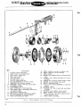
1.
REMOVE TORQUE CONVERTER.
a. See Figure 5. With transrmission and engrne
assembly out of truck, remove torque converter (3)
when separating transmission from engine) see
Towmotorqlle replacement.
u
SERVICE Movers
MIMS Machinery
mimsriggers.com
MANUAL
1
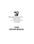
Ref.
No.
i
2
3
4
5
Descripticln
CASE, torque converter
BEARING, ball| converter case
CONVERTER ASSEMBLY, torque
C,OVER' torque converter case
GASKET, converter oil p\1mP
6
NUT,hexltCOVertOCaSe
7
8
NUT,hex.|covertocase
NUT, hex.} trams-ission case to cc)TIVerter Case
9
lO
ll
l2
HOUSING ASSEMBLY, pu-p
SEAL ASSEMBLY, oil
RING ASSEhABLY' collector
BUSHING
i
bl
i
l3
RING, seal| large
l4
l5
RING, seal, small
SCRE|h/, cap' collector ring to housing
l6
l7
l8
SCREW, c.apt collector ring to housillg
WASHER' lock. collector ring screw
WASHER. lock, collector ring screw
l9
20
2|
RING, retainer| converter case bearing
RING, retainer. output shaft and valve
SCREW' cap| converter pu-p to converter case
22
23
z4
SCREW' cap| ccrver tocase
SCREW. cap, cover tocase
SCREW, cap, torque converter case to transmit.Sic)n CaLSe
25
26
SEAL, converter c:age to transmission Case
SEAL, converter cc)ver| lower
Z7
28
29
3O
3l
32
SEAL, coI`Verter COVer| upper
WASHER, flat, cover tc) case
|ll/ASHER, flat' cover to case
\l/ASHER, lock, c.over to case
WASHER, lock, cover to c-a-se
WASHER, lock' transmission case to torque cclnverter Case
33
34
35
36
37
WIRE, locking, converter pump to converter case
SCREW' cap| converter to flywheel
SCREW, cap' trams-ission to flywheel housing
WASHER' lock, transmission to flywheel housing screw
WIRE, 1ocking' tclrque converter to flywheel
A
Fig.
5.
Converter'
Converter
Case
and
Oil
Pump
ll
MIMS SERVICE
Machinery Movers mimsriggers.com
MANUAL
u
'.:..
\
\^, i
t!_I
:.I.
``..
U
i
Re£I
No.
I
2
3
4
5
6
7
8
9
lO
ll
lZ
l3
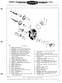
Description
LEVER, clutc:h operating
LINK. lever topressure plate
PIN, cotter, anchor pin
PIN, lever anchor
PIN, linkpivot
PLATE, clutch cover
PIJATE, clutch pressure
PLATE ASSEMBLY, reverse clutch
BEARING, ball| shi£ter carl.ier
BEARING, needle, forward clutc.h shaft
CARRIER, shifter
FLYWHEEL, clutch
LINK ASSEMBLY, shift opeI.ating
l4
PIN, cotter' linkto operating yoke and opCrating cylinder
l5
PIN, grooveJ Snifter ring
|6
|7
18
PIN, link to yoke and operating cylinder
PLATE ASSEMBLY. forward clutch
PLUG, operating yoke shaft
Fig.
12
6.
Clutch
Assembly.
l9
20
2l
22
RING, retainer' carrier to shifter ring
RING, retainer, carrier bearing
RING, shilter
SCREW, c.ap| shifter sleeve totransmission
23
SCREW, cap| clutch assemblyto clutch
flywheel
SCREW, cap| converter cutput shaft to clutch
SCREW, set, operaLting yoke Shaft
SHAFT, operating yoke
SIIAFT and VALVE ASSEMBLY' cc)nverter
ou+put
SLEEVE' shifteI.
WASHER. flat, link to yoke and operating
cylinder
WASHER' lock, shi£ter sleeve screw
WIRE, locking. clutch cover screw
WIRE, |clcking' converter output shaft to
clutch flywheel Screw
YOKE, snifter operating
CL±Se
24
Z5
26
Z7
Z8
29
3O
3l
32
33
Cat-rler
and
Linkage
U
SERVICE Movers
MANUAL
MIMS Machinery
mimsriggers.com
1
".`.i
`: tit
a:i:?i..I
i=
I :`t
ed;;,i
\ \
\\\
ii=
E=
:.-cfu
_-?.
i;.f!
zi
i 3i(2;2i.;ii
:,
;_i
l`\
i
"!8
2i
Description
A
I-'£"1
I
C,ASH, transmissioTl
2
3
4
5
6
7
8
9
lo
ll
BEARING' bal|' forward clutch shaft
BEARING, ball, idler gear shaft (front)
BEARING, ball, output shaft (rear)
BEARING' ball, reverse clutch shaft
BEARING, ball, idler gear shaft (rear)
BEARING, ball, output shaft (front)
BREATHER' transmission case
COVER and SEAL ASSEMBLY. output
shaft (front)
SEAL, oil, output shaft
COVER, idler gear shaft
1
z7
RING, retainer| clutch forward ShaLft
z8
RING, retaLiner| idler gear shaft
bearing
z9
RING, retainer, output Shaft, front and rear
bearing (s-all)
3O
RING, retainer' output shaft, trout bearing
3l
(large)
SCREW andWASHER, ca-p. casetO
converter housing
SCREW, cap, output shaft front Cover
l2
COVER, traLnSrniSSiOn Case top
l3
GASKET, idler goal. Shaft Cover
3Z
l4
l5
GASKET, output shaft lrorlt cover
GASKET, trams-ission case top cover
33
SCREW' car)I transmission C-aSe top Cover
34
SCREW and WASHER, idler gear shaft
l6
GEAR, forwaLrd
l7
l8
l9
20
2l
z2
GEAR, forward idler
GEAR, output shaft
GEAR, reverse
KEY' reverse gear
KEY' woodruff, idler gear
NUT, hex'| case to converter housing
35
Cover
SCREW and WASHER, tran5-iSSiOn Case
Z3
24
z5
PLUG, output gee-I
PLUG, magnetic. drain
PLUG, oillevel
26
RING, retainer, reverse gear. and reverse
gear shaft bearing
Fig_
7_
COVET
Case'
36
37
38
39
40
4l
42
43
Covers,
SIIAFT, reverse clutch
RUSHING, shaft
SIIAFT, forward clutch
SIIAFT' idler gear
SPACED, idler gear
WASIIER, 1clck, case to converter housing
WASHER, lock, output shaft cover screw
WASIIER, lock, trams-isSiOn Case top
cover Screw
Gears
and ShEIttEl
13
MIMS Machinery
Movers mimsriggers.com
SERVICE
MANUAL
I/
u
I
a
3
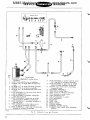
BRACKET ASSEMBLY, relief valve
mounting
C:LIP, hose| re|ief valve to radiator
ELBOW, 900, in right side ol converter
13
HOSE ASSEMBLY, shifter control valve
l4
HOSEASSEMBLY, upper tee at relief
valve to upper radiator connection
l5
SCREW, cap, reliefvalve' mountiTlg
l6
bracket to case
STRAINER ASSEMBLY
to 3-waLy tee in COnVerter housing
Case
4
5
6
7
8
9
lO
ll
l2
ELBOW, 45O, in shift operating cylinder
ELBOW, 45O, in strainer asse-bly
ELBOW, 9OO' intransmission case front
Cover
HOSEASSEMBLY, converter case tee to
tee in relief valve
HOSE ASSEMBLY, flexibleI COnVerter
case tee to clutch
HOSEASSEMBLY, lower tee at relief
valve to lower radiator connection
HOSE ASSEMBLY, operating cylinder to
control valve
HOSEASSEMBLY, reliefvalve tee to
3-way tee in cc,nverter housing
HOsEASSEMBLY, right side on converter
housing to strainer assembly
FIB.
14
8.
l7
|8
l9
2O
ZI
TEE, 90C}, inreliefvalve
TEE, 3-way in converter housing
TEE, 1atera|| in I.elief valve
TEE, conveI.tor Case
VALVEASSEMI3LY, I.elief
22
CAP, adjust-ent
23
24
25
26
PLUNGER
RING, seal
SEAT, plunger
SPRING, plunger
27
28
WASHER, plunger SPI.ing
WASHER, lock, relief valve lrlOunting
HydrBu11c1-1nes
bracket
and
Flttinga
u
MIMS Machinery
mimsriggers.com
SERVICE Movers
MANUAL
1
2.
REMOVE AND I)ISASSEnmLE HYDRAULIC
LINES, FITTINGS AI\un CONTROL VALVE
a. See Figure 8.
fittings.
Disconnect hydraulic linesand
b. See Figure 10. Remove screws and washers
(28, 29 and 31), then separate controlvalveassembly and ga.sket (27) from transmission case. To
disassemble a,ontrol valve for repair purposes,
refer to Control Valve repair section.
3.
REMOVE TOR UE CONVERTER CASE CC)VER
AND TRANSMISSION TOP COVER.
a. see Figure 5. Remove screws (22 and 23),
washers (28, 29, 30 and 31) and nuts (6and7),
then remove cover (4) and cover seals (26 and 27).
b. See FiguI.e 7. Remove screws andwasherS
(33, 35 and 43) and separate top cover (l2) and
gasket (15) from transmission case (1).
REMOVE AND
ASSEMBLY.
1
DISASSEMBLE
OIL
PUMP
a. see Figure 5. Cut lock wire (33) and remove
screws (21), then separate oil pump a.ssembly (9
through 18) and gasket (5) from inside converter
case. To disassemble oil pump) refer to Oil Pump
repair section.
5.
REMOVE AND DISASSEMBLE COI\IVERTER
CASE WITH CLUTCH FLYWHEEL APD OUT=
PUT SHAFT ASSEMBLED.
a. See Figure 6. Cut lock wire (31) and remove
screws (23) fastening clutch assembly (1 through 8)
to clutch flywheel (|2).
b. see Figure 5. Remove nuts, SCreWS and
wa.sheI.S (8, 24 and 32), then sepaI.ate Converter
caseJ With Clutch flywheel and Output Shaft assembled, from tI.anSmiSSiOn Case. Remove large seal
c. see Figure 6. Remove bearing (10) from
flanged end of output shaft 027).
d. see Figure 5. Ren`overetainerring(20),then
press clutch flywheel and output shalt asselrlbly
out of converter case bearing (2).
e. See Figure 6. Cut lock wire (32) and remove
screws (24) securing output shaft (27) to clutch
flywheel (12).
i. see Figure 5. Remove retainer I.ing (19) and
press bearing (2) out of converter case (1).
r\
REMOVE AND I)ISASSEMBLE CLUTCH
ASSEMBLY.
a.
See Figure 6. Remove forward clutch plate
(17) from face of clutch pressuI.e Plate (7).
b.
see Figure 6.
7.
REMOVE SHIFT
AND SHAFT.
a.
Lift out clutch asserrlbly (7, 8
See Figure 6.
OPERATING
LINK
YOKE
Remove cotter pins) washers
and link pins (14, 29 and 16) fI.OminSide transmission case, Lift out link (13).
b.
See Figure 6.
Remove set screw (25),then
using a brass drift and hammer, drive against eitller
plug (18) until the opposite plug (18) pops out and
the yoke shalt (26) is exposed. Drive onthe exposed
yoke shaft, in the opposite direction, untilthe other
plug (18) pops out. Continue driving/&ntil yoke`Shaft
is removed. Remove operating yoke. (33).
8-
REMOVE ANI) DISASSEMBLE CARRIER ANT)
BEARING, AND SHIFTER SLEEVE.
a.
See Figure 6.
Slide carrier andbearing aS-
sembly} (9, ll, 15, 19, 20 and 21) assembled, from
snifter sleeve (28).
b. See Figure 6. To disassemble carrier and
bearing) remove retainer ring (19) and press carrier (l1) out of snifter ring (21). Remove retainer
ring (20) and press bearing (9) out of shifteI. ring.
c. See Figure 6. Remove screws andwasherS
(22 and 30) and separate shifter sleeve (28) from
transmission case.
9.
REMOVE AND DISASSEMBLE SHIFT OPERATING CYLINDER.
a.
(14)
see Figure 9. Remove screws andWaSherS
and separate shift operating cylinder (1)
from transmission case. To disassemble shift
operating cylinder, refer to Operating Cylinder
repair section. Keep shims (l6) intact for use in
reassembly.
10.
ring (25).
6.
and 6). To disassemble clutch for repairpurposesJ
refer to Clutch Repair section.
REMOVE AND DISASSEnne1'E FORWARD
CLUTCH SHAFT AND GEAR.
a. see Figure 7. Removeretainerring(27),then
press forward clutch shaft (38) out of bearing (2).
Remove gear (|6).
b. see Figure7.
mission case.
ll.
Removebearing(2) fromtrans-
REMOVE AND I)ISASSEMBLE
CLUTCH SHAFT ANT) GEA
REVERSE
a. see Figure 7. Remove fI.Ont retainer ring
(26) and press reverse clutch shaft (36) with bearing (5) assembled out of transmission Case. Lift
out gear (19).
b. see Figure 7. To disassemble reverSeClutch
shaft and bearing} remove key (20), then press
bearing (5) off shaft. Remove rear retainer ring
(26) from shaft.
l5
MIMS Machinery
Movers mimsriggers.com
MANUAL
SERVICE
12.
REMOVE AND DISASSEMBLE IDLER GEAR
SHAFT COVER SHAFT AND GEAR.
a-. see Figure 7. Remove screws andWasherS
(34) and separate cover (ll) andgasket (13) from
transmission case.
b. see Figure 7. Remove retainer rings (28).
press shaft (39), with bearing (3) assembled, out
of transmission case. Remove gear (17) andspacer
(40). Press shaft (39) out of bearing (3). Remove
key (21) from shalt.
c.
13.
Remove bearing (6) from tra.nsmission case.
FIEMOVE AND DISASSEMBLE OUTPUT
SHAFT COVER AND GEAR ASSEMBLY.
3.
ASSEMBLE AND INSTALL REVERSE CLUTCH
SHAFT AND GEAR.
L
a. see F'igure 7. If hushing (37) was removed
from shalt (36) install new busking. InstallreaI.retainer ring (26) in groove nearmiddleofshaft, then
install bearing (5). Install key (20) in shalt. Place
gear (19) in position and press shaft into gear. Secure gear to shaft with front retainer ring (26).
4. ASSEMBLE AND INSTALL FORWARD CLUTCH
SHAFT AND GEAR.
a. See Figure 7. Install bearing(2) intransmission case. Place gear(16) inpositionandslide shaft
(38) through hollow shaft (36) and engage splines
in gear. Press shalt (38) intobearing(2) and secure
a. See Figure 7. Remove screws (32)andwashers (42) fastening cover (9) to transmission case.
with I.etainer ring (27).
b. See Figure 7. Remove retainer ring (29t, at
plug end of gear, and press complete coverJ gear
5.
ASSEMBLE Ann INSTALL SHIFT OPERATING
CYLINDE R.
and shalt assembly (4, 7,9, 10, 18, 29 and30) out
a. See Figure9. Assembleshiftcylinderasdesof transmission case. Remove gasket (14).
cribed in repair section. Place same number of
shims (16), removed in disassembly) onshiftoperc. See Figure 7. To disassemble cover and
ating cylinder and install against transmission
gear assembly) remove oil seal (10) and retainer
case. Secure with screws and washers (14).
ring (29). Press gear assembly out of cover (9).
Remove retainer ring (30) and press bearing (4)
NOTE
out of cover. press gear (18) out of bearing (4).
If new case or shift operating cylinder
Do not remove plug (23) from gear (18) unless
is used, adjust clearance as described
replacement is necessary.
in adjustment section.
ASSEMBLY
ASSEMBLE TRANSMISSION.
Assemble the Tow-
moTorque transmission as outlined in the following numbered procedures.
1.
6.
ASSEMBLE AND INSTALL OUTPUT SHAFT
GEAR AND COVER ASSEMBLY.
a. See Figure 7. If plug (23) was removed from
gear (18), install new plug. Press bearing (4) on
gear (18) and secure with retainer ring (29). Press
bearing (7) in cover (9) and secure with retainer
ring (30). Install gear, with bearing assembled, in
cover (9) and secure with retainer ring (29).
ASSEMBLE AND INSTALL SHIFTER SLEEVE,
AND CARRIER AND BEARING.
a. see Figure 6. Install snifter sleeve (28) and
secure with screws and washers (22 and 30).
b. See Figure 6. Install bearing (9) in shifter
ring (21) and secure with retainer ring (20). Install
carrier (ll) in shifter ring bearing and secure
with retainer ring (19). Slide complete assembly
on snifter sleeve (28).
7.
ASSEMBLE AND INSTALL SHIFT OPERATING
YOKE SHAFT AND OPERATING LINK.
place on cover,then install cover assembly in trans-
a. see Figure 6. Place shift operating yoke(33)
in position and install operating yoke shaft (26).
Secure shaft with set screw (25). Install plugs(18).
Install links (13) and connect to operating cylinder
mission case. Secure cover with screws (32) and
washers (42). install new oil seal (10) in cover.
pins (16, 29 and 14).
2.
8.
b.
see Figure 7.
Positioll a newgasket(14) in
ASSEMBLE ANDINSTALLIDLERGEARSHAFT
AND COVER.
a. See Figure 7. Install key (21) in idlershaft
(39). Position gear (17) in transmission case) then
press shaft and key into gear. Install spacer (40)
and bearings (3 and 6). Secure bearings with retainer rings (28).
b. Install gasket (13), cover (|1), then secure
with screws and washers (34).
16
'_I
and operating yoke with pins, washers and cotter
ASSEMBLE AND INSTALL CLUTCII
ASS EMBLY.
a. See Figure 6. Assemble clutch asselrlbly aS
described in clutch repair section. Install complete
assembly (7, 8 and 6). Make certain that all clutch
levers (1) are inserted in snifter ring groove (21)
and that reverse clutch plate splines are fully
engaged on reverse clutch shalt.
b.
See
Figure 6.
Install forwaLrd Clutch Plate
L
MIMS Machinery
mimsriggers.com
SERVICE Movers
MANUAL
1
i:#y=##eo:=oervth=td=lljtncehs sof#tch plate are
OIL PUAAP
DE SCRII) TION
9.
ASSEMB1.E AND INSTAI.L CONVERTER CASE
WITII CLUI'CH FLYWIIEEL At\ro OUTPUT
SHAFT ASSEMBLED.
a. see Figure 5. Install bearing (2) inconverter
case (1) and secure with retainer ring (19).
b. see Figure 6. Assemble output shaft (27) to
clutcll flywheel (12) and secure with screws and lock
wire (24 and 32).
a. see
F'igure 6. Install clutch flywheel and
output shaft (12 and 27) in converter case bearing
and secure with retainer ring (20). Install bearing
OIL PUMP REPLACEMENT
washers (8, 24 and 32).
To remove oil pumP} it iS necessary tO remove
the transmission from the vehicle (See TowmoTorque Replacement). With transmission Out of
vehicle and oil drained from the unit, slide torque
converter off converter output shaft and oil pump
collector ring. Remove lock wire, Screws and
washers and oil pump from converter case.
10.
when installing oil pumpJ use a new gasket (dO
not use sealing cc)mpound) between oil pump and
(10) in flanged end of output shalt.
d.
see
Figure
5.
Place new seal ring (25) in
position on tra,nsmission case and instau converter. case assembly. Secure with nuts, screws and
|
The transmission Oil Pump iS mounted On the
front side of the torque converter case directly in
front of the torque converter. Its function is tO
supply the necessary oil pressure to the torque
converter} hydraulic control system , and lubrication and oil cooling to the clutch forward and reverse plates. The oil pump is driven by the tor.que
converter through two driving lugs.
a.
ASSEnneLE AND INSTALL OIL PUMP
ASSEMBLY.
Assemble oil pump as described in repair
section.
b- See Figure 5. Place newgasket(5)(donotuse
sealing compound) in position and install oil pump
(9 through 18). Secure pump with screws (21t, and
lock wire (33).
converter case. slide torque converter over splines
of converter output shaft and oil pump collector
ring and make sure drive lugs of torque converter
aI.e engaged fully With notches Cut in the Oil pump
internal gear. Install transmission and fill tO Proper oil level. Refer to "Oil CheckingJ Drainingand
Filling" for proper procedures.
OIL. PUMP REPAIR
ll.
INSTALL TRANSMISSION TOP COVER ANI)
TORQUE CONVERTER CASE COVER.
a. see Figure 7. Place anewgaSket(15)imposition and install top cover (12). Secure with screws
and washers (33, 35 a 43).
b. see Figure 5. Place sea.ls (26and27) inposition on cover (4) and install on converter case.
secure with screws (22 and 23), washers (28] 291
30 and 3l), and nuts (6 and 7).
12.
ASSEMBLE AND INSTALL CONTRC)L VALVE
FITTINGS AND HYDRAULIC LINES.
a. See Figure lO. Assemble control valve aS
described in repair section. Install control valve
using a new gasket (27) against transmission case
and secure with screwsandwashers(28,29and 3|).
b. See Figure 8.
tings.
1
13.
Install hydraulic lines and fit-
INSTALL TORQUE CONVERTER.
a. see Figure 5. Install torque converter (3)
when assembling transmission to engine, see TowmoTorque replacement.
If the oil pump is found tO befaultyJ it iS rec-
ommended that an exchange pumpbeprocuredfrom
your Towmotor Representative.
See Figure 5. Remove
Disassemble Oil Pum
four 5/16 inch diameter socket head screws (15)
and one 1/4 inch diameter socket head screw (let.
Tap along parting line and separate Oil collector
ring (ll) from pump housing (9). Remove |ar,ge
and small "Ou rings (13 and 14). Lift outpumP
gears. RelnOve Oil Seal (10) from pump housing.
clean and Inspect Oil Pump. Was all parts in a
clean solvent and dry with compre ssed air. Inspect
gears and body for evidence of wear or damage.
If excessive wear or clearances iS evident install
a new pump body and gears. Note: Gear.S and body
are matched and must be replaced as a unit. Inspect face of collector ring for scratches, scoring
or excessive grooving, inspect bearing also.
use new "o» rings} oil seal andgasketwhen reassembling pump.
See Figure 5. Install gears
Assemble Oil Pum
in pump body and make surethesideof the internal
gear with driving lugs is towardthe outside. Lubricate the gears with Automatic Transmission Fluid.
17
MIMS Machinery
Movers mimsriggers.com
MANUAL
SERVICE
I,osition large and Small "O" rings (13 and 14) in
collector ring and assemble Collector ring (|1) to
pump housing. secure assemblies together with
socket head screws (15 and 16). Check freeness of
gear rotation after assembling.
plate, operating levers) links, or cover is necessary} a complete clutch cover assembled with
these items must be replaced because of alignTrlent
on the clutch operating levers. This clutch cover
assembly is available from your Towmotor Factory
Representative on an exchange basis.
DUPLEX CLUTCH AND SHIFTING
Disassemble Clutch. See Figure 6. The Clutch
Cover assembly is made up of matchedparts. When
disassembly is contemplated note the match mal.kings} one on the extension lug of the pressure
plate] and one matching mark on thecoveradiacent
to it. On reassembly make sure these two marks
are in the same relation. The pressure plate,
cover, levers and links are not individually replacable. If any of these are damaged replace the
complete clutch cover assembly with a new or rebuilt assembly. Levers and links must be kept in
same relation to this position and levers must not
be turned over. Remove cotter pins (3) and lever
clevis pins (4) fastening operating levers to clutch
LINl(AO|
DESCRIPTION
The duplex clutch is a double pressure plo.te type
with two driving plates and is oil cooledby a spray
system. Clutch plates are coned to assuI.e quick
release from the pressure plates. Control of direction is handled through a shifter ring engaging the
clutch operating levers. Snifter ring is movedback
and forth by a yoke supported on a shalt. Shift operating cylinder piston rod is connected tothe yoke
through linkage.
CLUTCH ANI) SIIIFTER CARRIER
REPLACEMENT
To remove clutch assembly it ls suggested that
the transmission be removed from the vehicle}see
TowmoTorque Replacement. With tI.anSmiSSiOn
removed and oil drained from the unit, slide torque
converter off conveI.ten Output Shaft and Oil Pump
collector ring. Remove tI.anSmiSSiOn top Cover.
Cut wire and remove screws fastening clutch assembly to clutch flywheel. Remove bolts nuts and
washers securing converter case to transmission
case. Lift off converter case with oil pump and
clutch flywheel assembled. Remove forward clutch
plate. Lift out clutch assembly. Slide off clutch
carrier assembly.
lhThen installing clutch assembly be sure that all
clutch operating levers are in the groove of the
clutch shifter I.ing and that Clutch Plates are installed properly) clutch plate hubs must face the
inside of the transmission or the unit cannot be
assembled properly.
With clutch assembly installed, place fc)rward
clutch plate on clutch pressure plate and slide
splines of hub over splines of forward clutch shaft.
Insert new "O" ring between cases and install
converter case, with oil pump and clutch flywheel
assembled, against transmission case and secure
with bolts) nuts and washers. Using a drift, align
holes in clutch cover with holes in clutch flywheel.
Install screws and lock wire in pairs. Install top
cover. Slide torque converter in place and install
transmission, see TowmoTorque Replac'ement.
L
cover (6)I slide out clutch pressure plate (7) and
remove pivot pins (5), links (2) and levers (1). Lift
out clutch plate (8).
Disassemble Carrier] Bearing and Snifter Ring.
See Figure 6. Remove retainer ring (19) andpress
carrier (ll) out of snifter ring (21). Remove retainer ring (20) and press bearing (9) outof shifter
ring (21).
Clean and Inspect Clutch and Snifter Carrier.
Wash all parts in a cleansolventanddry with compressed air. Inspect clutch plates for wom linings
and loose hub rivets. Inspect operating levers>
links and pins for excessive wear, one at atime
and replace in original position. Inspect faces of
pressure plate aJld Clutch cover. Inspect carrier
bearing. Inspect bore of snifter carrier for excessive wear. Replace all faulty parts except, that if
COVer, Pressure Plate, levers Or links need replacing, replace the complete clutch cover assembly.
Red.ssemble
Clutch.
See
Figure
6.
u
With index
markings in proper relation on pressure plate
and cover, place clutch pla.te (8) on face of clutch
cover (6). Slide pressure plate (7) with links (2)
and pins (5) attached, in slots provided in clutch
cover. Clutch construction eliminates need for
cottel. pinning link pins. Align operating lever with
holes in clutch cover and install clevis pins(4) and
cc)tter pins (3).
Assemble Carrier, Bearing and Snifter Ring.
See Figure 6. Press bearing (9) in snifter ring
(2l) and secure with retainer ring (20). Press
carrier (Ill in shifter ring (21) and secure with
retainer ring (19).
CLUTCH AND SHIFTER CARRIER REPAIR
If clutch assembly is found to be faultyl because
of excessive clutch plate slippage or because it,s
completely worn out, repair parts are available to
a certain extent, that isl if replacement of pressure
18
SHIFT OPERATING CYLINDER
DE SCRIP TION
The shift operating cylinder is mounted on the
|J
MIMS Machinery
mimsriggers.com
SERVICE Movers
MANUAL
1
bottom of the transmission case. Its function is to
change engagement of either forward or reverse
clutch plates by oil pressure admitted to either
side of the piston. The cylinder is double acting
and actuates the clutch through linkage connected
to an operating yoke.
SHIFT OPERATING CYLINDER REPAIR
as-l6
Ref.
a
-lO
E=-m
BODY
2
GUIDE, spring
3
NUT, piston shaft
4
PISTON
PLUG,end
6
RING, retainert
large
7
i
'''+''
-I
"C= -ll
tiEi,
"CT_>r
RING, retainer|
small
8
ROD, piston
9
SEAL, endplug
lO
SEAL, piston
ll
SEAL, pistoTl
l2
SPRING,upper
13
SPRING, lower
l4
SCREW and
WASHER,
3
?
cylinder to
transmission
Case
l5
SEAL, cylinder
to tI.anSmiSSiOn
Case
l6
SPACER' cylinder
adJ uSting
(I/32 thick)
l6
cause of broken neutral springs or leakage pastthe
piston seal or end plug seal,itispossible to repair
the cylinder while the transmissic)n is installed in
the vehicle or with the transmission removed from
the vehicle.
SHIFT OPERATING CYLINDER REPLACEMENT
(with transmission installed in vehicle
5
Ei=-h
I
Description
I
I
|
If the opeI.ating Cylinder. iS found tO be faulty be-
No.
SPACED, cylinder
adjusting
(I/8 thick)
see FiguI.e 9. To disassemble, remove end Plug
retainer ring (7). Screw a 3/8-16NC bolt in the
tapped hole of the end plug and use as aPu|ler.
Remove the piston nut (3). Remove screws and
washers (14), then pull the cylinder body free Of
the transmission case, leaving the piston rod attached intact. Reassemble in the reverse manner
using a new gasket between cylinder and case.
AfteI. inStaLllation of shift cylinder., Check for
clutch neutral setting.
section and figure 4.
Refer to "Adiustments"
SHIFT OPERATING CYLINDER REPLACEMENT
(with transmission removed from vehicle
To replace shift operating cylinder it iS neCeSsaI.y tO diSasSemble the transmission Only as far aS
follows: Disconnect lines at cylinder, remove COnverter, converter case with oil pump and clutch
flywheel and output shaft assembled, and complete
clutch assembly. Disconnect shift Cylinder linkage
at operating yoke. Remove screws and washers
and withdraw shift cylinder and shims.
lThen installing shift cylinder, use anew seal ring
between cylinder and case. Connect link asSemblyInstall clutch assembly) converter Case With Oil
pump and clutch flywheel and output shaft assembled. Connect lines tocy|inder and install converter.
After installation of shift cylinder, Check for
clutch neutral setting. Refer to "Adjustments"
section and figure 4.
Disassemble Shift Operating Cylinder.
mission removed fI.Om truck.)
|
see Figure 9. To disassemble cylinderfor cleaningJ inspection Or repair PurPOSeSJ remove large
retainer ring (6) at bottom of cylinder. Screw a
3/8-16NC bolt in tapped hole of the endPlug assembly (5) and use as a purler. To disassemble
I-B901- 1
Fig.
(with trans-
9.
Sh1|t
Operatln4
C'ylirlder
Assembly
end plug assy) use a vise or arbor press and com-
19
MANUAL
SERVICE
MIMS Machinery
Movers mimsriggers.com
L
m
7
5
"::-§_:5¥:
j¬
E=
3
I-i-i=;
i ;.-`.
RNeof..
BODY, shifter control valve
BRACKET, bellcrank support
3
4
5
CAP, accu-ulator valve
GASKET, accumulator valve cap
HOUSING, forward and reverse plunger
6
7
8
9
PLUG'pipe
BODY' plunger
lO
EYE, plunger
RING, seal, plunger eye
RING, snaLP
SPRING, compression
VALVE, plunger
PLUNGER ASSEhABLY, forward and reverse
BALL, forward and reverse plunger
SPRING, compression
PLUNGER, acclJ--ulatOr Valve
RETAINER, forward and reverse plunger
RING, seal, plunger
RING, snap' forward and reverse plunger
RING, wiper, control valve plunger
SEAL, oil, clutch shaft
SCREW, bracket tc) control valve
23
SCREW' mach., plunger retaiTler tC, COntrOI Valve
24
SPRING, accu-u|ator valve
25
26
WASHER, plaint forward and reverse plunger
WASHER, lock, bellcrank support bracket
27
GASKET, contI.OI Valve tO tra-nSmiSSiOn Case
28
29
30
3|
SC,REV, cap| control valve mounting
SCREW, cap| control valve mounting
SWITCH, limit
WASIIER, lock, shifter valve
Fig.
20
:;22
De s crlPtiOn
I
2
ll
l2
l3
l4
l5
l6
l7
l8
|9
20
2l
22
;i`
10.
C.ontroI
VEIIVe
AaBembly
|
MIMS Machinery
SERVICE Movers mimsriggers.com
MANUAL
\
release press or vise slowly and remove guide (2) )
=er.e.a.Bseapprr'e=8=,'dVe==eS=.OwV,eyr=d-i.nee=.r*.g#ld,.t(h2a?
and spring (13). Remove end plug seal (9t from
end plug (5).
unscre-w piston rod nut (3) and remove piston (4)
and "o" ring (ll) assembled Iron piston rod (8).
Compress other spring guide and remove retainer
ring (7), spring guide (2) and spI'ing (12).
Cylinder. Wash
Clean and Ins ect Shift
all parts in aclean solvent anddrywit compressed
air. hspect cylinderbore for scratches andgrooves
which would caLuSe Cutting Or SCratChing the Seal
ring and cause leakage. Use new seal rings when
reassembling cylinder.
eratin Cylinder.
mission removed from truck.
AsseTnble Shift
(with trans-
see Figure 9. Insert small diameter spring (12)
and spring guide (2) over boss in cylinder body.
compress spring and install retainer ring (7).
Install piston (4), with new seal ring (10) assembled in bore, and slide over piston rod end. Note,
piston is equipped with recess for nut, install with
recess toward nut. secure piston with nut (3).
position large diaIY\eter spring (13) and SPI.ing
guide (2) on end plug (5) and secure with retainer
ring (7). Install new seal ring (9) on endplug (5)
i
and
install
in botton`
of cylinder.
secure
plugplug
with assembly
large retainer
rlng (6).
DESCRIPTION
The control valve is mounted On the front Cover
of the transmission case. Its function is to distribute
oil under pressure to the shift operating cylinder.
The control valve consists mainly of a housing in
which two plungers are fittedto controloil direction
thr.ough valve. One plunger is operatedby thetranSmission shift lever and the other plunger is operated bythe creeper pedal. The creeper pedalplunger
is equipped with a relief valve to control maximum
pressures in the system.
CC)NTROL VAT.VE REPLACEMENT
See Figure |0.
oil
lines
Remove
screws (28 and 29) and washers (31) fastening valve
to transmission case.
i
(26) and remove retainer (17) and bracket (2).
Remove wiper rings (20) and seal rings (18). Remove plug (6) and limit switch (30). Mark valve
plungers so that they can be returned to their or'iginal position if used in reassembly. Remove
plunger.
The forward and reverse plunger (|3) is equipped
with detent balls and aspring. lThen disassembling}
care should be taken when removing the plunger
(l3) from the housing (5) as the decent balls (14)
and spring (15) will pop out. Remove snap ring'
(19t and washer (25).
The creeper valve plunger (7) is equipped with a
relief valve. To disassemble, unscrew and remove
plunger eye (8) and seal ring (9t. Remove spring
(ll) and valve (12).
The control valve is equippedwith an accumulator
valve. To disassemble, unscrew and remove Cap
(3), gasket (4), spring (24) andplunger (16). Remove
clutch shaft oil seal (21).
dry compressed a,ir. Inspect relief valve and seat
for grooves and scratches that may cause poor
seating. Inspect plungers for grooves Or excessive
wear._ check fit of plungers in housing. There should
be no perceptible side play. If plungers are loose
or faulty in other respects, replace valve assembly.
use new gaskets and seals when reassembling
control valve.
Assemble Control Valve. See Figure 10. Insta.ll
new plunger seal rings (18) and wiper rings (20)
in housing. Install plunger (16) and spring (24) in
bore of housing (1) and secure with new gasket
(4) and cap (3).
To remove control valve, disaLnd COntrOl linkage.
Disassemble Control Valve. See Figure 10. To
disassemble valve for cleaning or inspection purposes| remove screws (22 and 23) and washers
Clean and lns ect Valve. Wash all parts in aclean
solvent. Blow out all pasEiageS in va.1ve housing with
CONTROL VALVE
connect
control valve requires no service other than cleaning if the valve should become inoperative due to
dirt or other foreign matter in the oil system.
To prevent this situation from occurring| the oil
in the system must be kept clean and free of all
dirt or sediment.
install relief valve (12) and apring (Ill inbore of
creeper valve plunger and secure with new Seal
ring (9) and eye (8). Insert plunger (7), with snap
ring (10) assembled, in valve housing.
vThen installing control valve, use a gasket (27)
between valve and case. Connect linkage. Check
linkage for fI.ee OPeratiOn and Correct adjustment,
see Adjustment Section. Connect oil lines.
Install washer (25) on plunger (13) and secure
with snap ring (19). Install detent balls (14) and
spring (|5) in plunger (13t and slide housing (5)
over end of plunger until balls slip into recessed
groove. Install complete plunger in valve housing.
CONmOL VALVE REPAIR
position retainer (17) and bracket (2) over plungers and secure with screws (22 and23) and washeI`
(26). thstall limit switch (so) plug (6) and shalt
If the control valve is found tO be faulty) it iS
recommended that a cc)mplete valve be procured
from your Towmotor Factory Representative. The
seal. (21).
Z1
MIMS Machinery Movers mimsriggers.com
|
I