1
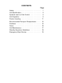
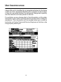
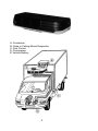
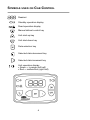
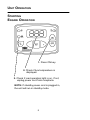
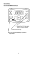
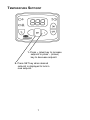
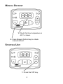
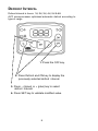
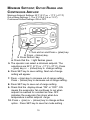
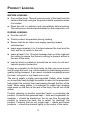
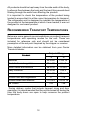
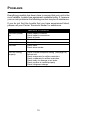
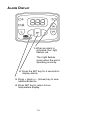
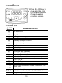
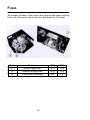
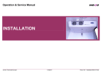
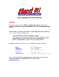
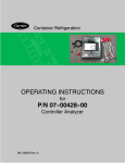
Carrier
Transicold
Truck
Refrigeration
30S
Operator’s
Manual
62-10042 Rev B
OPERATOR’S
MANUAL
TRUCK
REFRIGERATION UNIT
30s
Carrier Refrigeration Operations
Carrier Transicold, Carrier Corporation,
P.O. Box 4805, Syracuse, N.Y. 13221 U. S. A.
ã Carrier Corporation 2001 D Printed in U. S. A. 0301
Integra 30s OPERATOR’S MANUAL
This guide has been prepared for the operator of Carrier
Transicold diesel truck refrigeration units. It contains basic
instructions for the daily operation of the refrigeration unit as well
as safety information, troubleshooting tips, and other information
that will help you to deliver the load in the best possible condition.
Please take the time to read the information contained in this
booklet and refer to it whenever you have a question about the
operation of your Carrier Transicold Integra 30s unit.
Your refrigeration unit has been engineered to provide long,
trouble-free performance when it is properly operated and
maintained. The checks outlined in this guide will help to minimize
over-the-road problems. In addition, a comprehensive
maintenance program will help to insure that the unit continues to
operate reliably. Such a maintenance program will also help to
control operating costs, increase the unit’s working life, and
improve performance.
This guide is intended as an introduction to your unit and to
provide general assistance when needed. More comprehensive
information can be found in the Operation and Service Manual for
your unit. This manual can be obtained from your Carrier
Transicold dealer.
When having your unit serviced, be sure to specify genuine Carrier
Transicold replacement parts for the highest quality and best
reliability.
At Carrier Transicold, we are continually working to improve the
products that we build for our customers. As a result,
specifications may change without notice.
CONTENTS
Page
Safety . . . . . . . . . . . . . . . . . . . . . . . . . . . . . . . . . . . .
1
Unit Identification . . . . . . . . . . . . . . . . . . . . . . . . . .
2
Symbols used on Cab Control . . . . . . . . . . . . . .
4
Unit Operation . . . . . . . . . . . . . . . . . . . . . . . . . . . .
5
Product Loading . . . . . . . . . . . . . . . . . . . . . . . . . . 11
Recommended Transport Temperatures . . . . . . 12
Problems . . . . . . . . . . . . . . . . . . . . . . . . . . . . . . . . . 13
Fuses . . . . . . . . . . . . . . . . . . . . . . . . . . . . . . . . . . . . 16
Unit Maintenance . . . . . . . . . . . . . . . . . . . . . . . . . . 17
Standby Operation Guidelines . . . . . . . . . . . . . . 18
Emergency Road Service . . . . . . . . . . . . . . . . . . . 19
SAFETY
Your Carrier Transicold refrigeration unit has been designed with
the safety of the operator in mind. During normal operation, all
moving parts are fully enclosed to help prevent injury. During all
pre-trip inspections, daily inspections, and problem
troubleshooting, you may be exposed to moving parts; please
stay clear of all moving parts when the unit is in operation.
REFRIGERANTS
The refrigerant contained in the refrigeration system of your unit
can cause frostbite, severe burns, or blindness when in direct
contact with the skin or eyes. For this reason, and because of
legislation regarding the handling of refrigerants during system
service, we recommend that, whenever your unit requires service
of the refrigeration system, you contact your nearest Carrier
Transicold authorized repair facility for service.
1
UNIT IDENTIFICATION
Integra 30s unit is identified by a nameplate attached to the frame
of the unit. This nameplate identifies the complete model number
of the unit, the serial number, the refrigerant charge and quantity,
and the date the unit was placed in service.
If a problem occurs, please refer to the information on this plate,
and make a note of the model and serial number before calling for
assistance. This information will be needed when you contact a
technician or Carrier Transicold Service Engineer so that he or she
may properly assist you.
2
A: Condenser
B: Cube or Ceiling-Mount Evaporator
C: Cab Control
D: Compressor
E: Vehicle Battery
3
SYMBOLS USED ON CAB CONTROL
Readout
Standby operation display
Road operation display
Manual defrost control key
Unit start-up key
Unit shut-down key
Data selection key
Selected data decrement key
Selected data increment key
Unit operation display
S Green = in-range (left half)
S Red = malfunction (right half)
4
UNIT OPERATION
STARTING
ENGINE OPERATION
1. Press ON key.
2. Check if box temperature is
displayed.
3. Check if road operation light is on. If not,
unplug power cord from receptacle.
NOTE: If standby power cord is plugged in,
the unit will run in standby mode.
5
STARTING
STANDBY OPERATION
1. Press the OFF key and
plug in power supply.
2. Press the ON key.
3. Check that the standby operation
light is on.
6
TEMPERATURE SETPOINT
1. Press + (plus) key to increase
setpoint or press -- (minus)
key to decrease setpoint.
2. Press SET key when desired
setpoint is displayed to lock in
new setpoint.
7
MANUAL DEFROST
1. Check that box temperature is
40_F or lower.
2. Press Manual Defrost key to initiate
manual defrost.
STOPPING UNIT
1. Press the OFF key.
8
DEFROST INTERVAL
Defrost interval in hours: 1H, 2H, 3H, 4H, 5H & 6H
AUT: microprocessor optimized automatic defrost according to
type of cargo.
1. Press the OFF key.
2. Press Defrost and ON key to display the
previously selected defrost interval.
3. Press -- (minus) or + (plus) key to select
defrost interval.
4. Press SET key to validate modified value.
9
MINIMUM SETPOINT, OUT-OF-RANGE AND
CONTINUOUS AIRFLOW
Minimum Setpoint Settings: 32_F (0_C) or ---17_F (---27_C)
Out-of-Rang Settings: 1, 2 or 3_C (3.6, 5.4 or 7.2_F)
Continuous Airflow Settings: ON or OFF
1. Turn unit on and Press + (plus) key.
2. Press -- (minus) key.
3. Press Defrost key.
4. Check that the ! light flashes green.
5. The operator can select a minimum setpoint. The
selections are 32_F (0_C) or --17_F (--27_C). Press
+ (plus) key or -- (minus) key to change setting.
6. Press SET key to save setting. Next out-of-range
setting will appear.
7. Press + (plus) key to increase out-of-range setting.
Press -- (minus) key to decrease out-of-range setting.
8. Press SET key to save out-of-range setting.
9. Check that the display shows “ON” or “OFF”. ON
means the evaporator fan continues to run when
setpoint is reached for constant air flow. OFF
indicates the evaporator fan stops when box
temperature is within setpoint range.
10. Press + (plus) or -- (minus) key to change airflow
option. Press SET key to save fan mode setting .
10
PRODUCT LOADING
BEFORE LOADING:
D Pre-cool the body. This will remove much of the heat from the
inside of the body, and give the product better protection when
it is loaded.
D Place the unit in a defrost cycle immediately before loading.
This will remove moisture accumulated on the evaporator coil.
DURING LOADING:
D Turn the unit off!
D Check product temperature during loading.
D Ensure that the air return and supply opening remain
unobstructed.
D Leave approximately 4 to 5 inches between the load and the
front wall for air return to the unit.
D Leave at least 10 to 12 inches between the top of the load and
the ceiling to ensure that there is nothing to prevent airflow to
the rear of the body
D Load product on pallets to provide free air return to unit and
improve product protection.
Proper air circulation in the truck body, air that can move around
and through the load, is a critical element in maintaining product
quality during transport. If air cannot circulate completely around
the load, hot spots or top-freeze can occur.
The use of pallets is highly recommended. Pallets, when loaded
so air can flow freely through the pallets to return to the evaporator,
help protect the product from heat passing through the floor of the
truck. When using pallets, it is important to refrain from stacking
extra boxes on the floor at the rear of the truck, this will cut off the
airflow.
Product stacking is another important factor in protecting the
product. Products that generate heat --- fruits and vegetables, for
example --- should be stacked so the air can flow through the
product to remove the heat; this is called “air stacking” the
product. Products that do not create heat --- meats and frozen
products --- should be stacked tightly in the center of the trailer.
11
All products should be kept away from the side-walls of the body,
to allow air flow between the body and the load; this prevents heat
filtering through the walls from affecting the product.
It is important to check the temperature of the product being
loaded to ensure that it is at the correct temperature for transport.
The refrigeration unit is designed to maintain the temperature of
the product at the temperature at which it was loaded; it was not
designed to cool warm product.
RECOMMENDED TRANSPORT TEMPERATURES
Below are some general recommendations on product transport
temperatures and operating modes for the unit. These are
included for reference only and should not be considered
preemptive of the set point required by the shipper or receiver.
More detailed information can be obtained from your Carrier
Transicold dealer.
Setpoint Range
Product
_F
_C
Bananas
55 to 60
13 to 16
Fresh fruits and vegetables
33 to 38
0 to 3
Fresh meats and seafood
28 to 32
---2 to 0
Dairy Products
33 to 38
0 to 3
Ice
15 to 20
---10 to ---7
0
---18
---10 to 0
---23 to 18
---20
---29
Frozen fruits and vegetables
Frozen meats and seafood
Ice Cream
During delivery cycles that include frequent stops and door
openings, it is recommended that the unit be turned off during the
time the body doors are open to help conserve the product
temperature.
12
PROBLEMS
Everything possible has been done to ensure that your unit is the
most reliable, trouble-free equipment available today. If, however
you run into problems the following section may be of assistance.
If you do not find the trouble that you have experienced listed,
please call your Carrier Transicold dealer for assistance.
General Problems
Unit won’t power
up.
Check battery condition.
Check battery connections.
Check all fuses
Unit won’t start.
Check all fuses
Unit won’t run.
Check all fuses
Unit dies.
Check belts.
Check alarm codes.
Unit not cooling
properly.
Check minimum setpoint setting (see page 10).
Defrost unit.
Check evaporator for airflow restriction.
Check condenser for airflow restriction.
Check body for damage or air leaks.
Check product is loaded properly
Check refrigerant charge.
13
ALARM DISPLAY
1. When an alarm is
activated, the ! light
flashes red.
The ! light flashes
green when the unit is
operating correctly.
2. Press the SET key for 5 seconds to
display alarms.
3. Press + (plus) or -- (minus) key to view
additional alarms.
4. Press SET key to return to box
temperature display.
14
ALARM RESET
1. Press the OFF key to
clear alarm list. Unit
can now be restarted
if no active alarm
condition remains.
ALARM LIST
ALARM
Number
A00
A01
A02
A03
A04
A05
A06
A07
A08
A09
A10
A11
A12
A13
A14
A15
EE
bAt
--- --- ----- --- ----- --- ---
ALARM DESCRIPTION
No Malfunction
Low Pressure
High Pressure
Electric Motor Overload
Road Compressor Clutch
Standby Clutch and Contactor
Condenser Fan Motor
Evaporator Fan Motor
Not Used
Defrost Valve
Quench Valve
Condenser Valve (Optional)
Out-of-Range High Temperature
Out-of-Range Low Temperature
Defrost Cycle
Setpoint is out of controller temperature range of
---20.2_F to 86_F.
Return Air Sensor
Low Battery Voltage
Using Road Compressor & Standby Compressor at the
Same Time.
Setpoint is lower than programmed minimum setpoint,
but within controller range of ---20.2_F to 86_F.
ERR
Programming error on part of operator
15
FUSES
To access the fuses in the control box, remove the upper cowling
from unit, then open the control box (fastened by 3 screws).
Fuse
F1
F2
F3
Purpose
Road supply fuse
Standby supply fuse
Clutch fuse (Standby)
16
12V
30 A
30 A
5A
24V
15 A
15 A
3A
UNIT MAINTENANCE
WARNING
Before working on unit, check that:
D the unit (cab command) is OFF.
D it is impossible for unit to automatically start-up during
maintenance.
Refrigerant Charge: R134a 4lbs
Approved Oil
Mobil Arctic EAL 68
Compressor oil
Oil Charge
Road
Standby
250cc (.53 pint)
150cc (.32 pint)
For the most reliable operation and for maximum life, your unit
requires regular maintenance. Maintenance should be performed
on the following schedule:
SERVICE SCHEDULE
Monthly
Yearly
D Check tension of compressor belt(s).
D Check all bolts, screws and unit mounting bolts for
tightness. Tighten as required.
D Check motor brushes.
D Clean condenser and evaporator coils.
D Replace Road and Standby compressor belts.
D Replace filter-drier.
D Check operation of cab control.
D Change compressor oil.
D Check defrost:
--- Fans stop
--- Defrost ends automatically
--- Water drains from evaporator
D Check operation of evaporator and condenser fans.
D Check all belt tension pulleys.
17
STANDBY OPERATION GUIDELINES
For safe, reliable operation in Standby mode, it is important to
follow a few guidelines:
D
Always check that the unit is OFF (Cab Command) before
connecting or disconnecting the unit from power source.
D
The circuit breaker and power cord used for Standby
operation must comply with legislation currently applicable
on site of use and with unit specifications in table below.
Unit
Operating Voltage
Integra 30s
115 V
Single phase 60 hz
230 V
Single phase 60 hz
230 V
Three phase 60 hz
Voltage
115/1/60
230/1/60
208/1/60
230/3/60
D
Maximum Unit
Operating Amperage
18.2 A
9.0 A
3.8 A
Power Cord Length and Wire Gage
25 ft
50 ft
75 ft
100 ft
14
12
10
8
14
12
10
8
16
14
12
10
When multiple units are in use, each unit must be operated
on its own electrical circuit. You should never operate more
than one unit on a circuit breaker.
Important note: This information is provided as a guideline only.
When preparing a circuit for operation of the refrigeration unit, a
licensed electrician should be contracted. A licensed electrician
is familiar with all local ordinances and special requirements for
your area and can ensure that the circuits are properly designed,
installed, and connections are correct.
18
EMERGENCY ROAD SERVICE
At Carrier Transicold we’re working hard to give you complete
service when and where you need it. That means a worldwide
network of dealers that offer 24-hour emergency service. These
service centers are manned by factory trained service personnel
and backed by extensive parts inventories that will assure you of
prompt repair.
Should you experience a unit problem with your refrigeration unit
during transit, follow your company’s emergency procedure or
contact the nearest Carrier Transicold service center. Consult the
Shortstop Service Centers directory to locate the service center
nearest you. This directory may be obtained from your Carrier
Transicold dealer.
If you are unable to reach a service center, call our 24-hour
Action Line: (800)448-1661
When calling, please have the following information ready for
fastest service:
Your name, the name of your company, and your location.
A telephone number where you can be called back.
Refrigeration unit model number and serial number.
Box temperature, set point and product.
Brief description of the problem you are having, and what you
have already done to correct the problem.
We will do everything we can to get your problem taken care of
and get you back on the road.
19