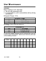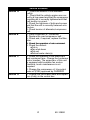
1
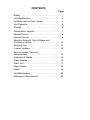
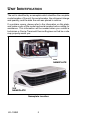
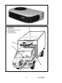
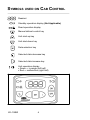
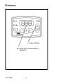
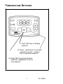
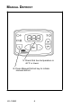
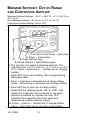
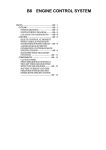
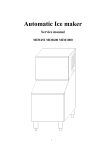
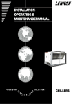
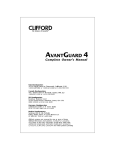
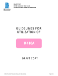
62-10892-A cvr-9x12.qxd
6/13/06
11:34 AM
Page 1
OPERATOR’S
MANUAL
X Series
Truck
Direct Drive
Truck Refrigeration Units
With
Cab Command Controller
OPERATOR’S MANUAL FOR
X SERIES DIRECT DRIVE TRUCK UNITS
WITH CAB COMMAND CONTROLLER
This guide has been prepared for the operator of Carrier Transicold
X Series direct drive truck refrigeration units using the Cab
Command controller. It contains basic instructions for the daily
operation of the refrigeration unit as well as safety information, and
other information that will help you to deliver the load in the best
possible condition. Please take the time to read the information
contained in this booklet and refer to it whenever you have a
question about the operation of your Carrier Transicold truck
refrigeration unit.
Your refrigeration unit has been engineered to provide long,
trouble-free performance when it is properly operated and
maintained. A comprehensive maintenance program will help to
insure that the unit continues to operate reliably. Such a
maintenance program will also help to control operating costs,
increase the unit’s working life, and improve performance.
This guide is intended as an introduction to your unit and to provide
general assistance when needed. More comprehensive
information can be found in the Operation and Service Manual for
your unit. This manual can be obtained from your Carrier Transicold
dealer.
When having your unit serviced, be sure to specify genuine Carrier
Transicold replacement parts for the highest quality and best
reliability.
At Carrier Transicold, we are continually working to improve the
products that we build for our customers. As a result, specifications
may change without notice.
CONTENTS
Page
Safety . . . . . . . . . . . . . . . . . . . . . . . . . . . . . . . . . . . .
1
Unit Identification . . . . . . . . . . . . . . . . . . . . . . . . . .
2
Symbols used on Cab Control . . . . . . . . . . . . . . .
4
Unit Operation . . . . . . . . . . . . . . . . . . . . . . . . . . . .
5
Starting . . . . . . . . . . . . . . . . . . . . . . . . . . . . . . . . . .
6
Temperature Setpoint . . . . . . . . . . . . . . . . . . . . . .
7
Manual Defrost . . . . . . . . . . . . . . . . . . . . . . . . . . . .
8
Defrost Interval . . . . . . . . . . . . . . . . . . . . . . . . . . . .
9
Minimum Setpoint, Out-of-Range and
Continuous Airflow . . . . . . . . . . . . . . . . . . . . . . . . . 10
Stopping Unit . . . . . . . . . . . . . . . . . . . . . . . . . . . . . 11
Product Loading . . . . . . . . . . . . . . . . . . . . . . . . . . . 12
Recommended Transport
Temperatures . . . . . . . . . . . . . . . . . . . . . . . . . . . . . 14
Problems & Alarms . . . . . . . . . . . . . . . . . . . . . . . . 15
Alarm Display . . . . . . . . . . . . . . . . . . . . . . . . . . . . . 16
Alarm List . . . . . . . . . . . . . . . . . . . . . . . . . . . . . . . . 17
Alarm Reset . . . . . . . . . . . . . . . . . . . . . . . . . . . . . . 18
Fuses . . . . . . . . . . . . . . . . . . . . . . . . . . . . . . . . . . . . 19
Unit Maintenance . . . . . . . . . . . . . . . . . . . . . . . . . . 20
Emergency Road Service . . . . . . . . . . . . . . . . . . . 22
SAFETY
Your Carrier Transicold refrigeration unit has been designed with
the safety of the operator in mind. During normal operation, all
moving parts are fully enclosed to help prevent injury. During all
pre-trip
inspections,
daily
inspections,
and
problem
troubleshooting, you may be exposed to moving parts; please stay
clear of all moving parts when the unit is in operation.
WARNING
Beware of unannounced starting of the unit. The unit
may cycle the fans and operating compressor unexpectedly as control requirements dictate. Press OFF
key on the Cab Command.
REFRIGERANTS
The refrigerant contained in the refrigeration system of your unit
can cause frostbite, severe burns, or blindness when in direct
contact with the skin or eyes. For this reason, and because of
legislation regarding the handling of refrigerants during system
service, we recommend that, whenever your unit requires service
of the refrigeration system, you contact your nearest Carrier
Transicold authorized repair facility for service.
1
62--10892
UNIT IDENTIFICATION
The unit is identified by a nameplate which identifies the complete
model number of the unit, the serial number, the refrigerant charge
and quantity, and the date the unit was placed in service.
If a problem occurs, please refer to the information on this plate,
and make a note of the model and serial number before calling for
assistance. This information will be needed when you contact a
technician or Carrier Transicold Service Engineer so that he or she
may properly assist you.
20X
NAMEPLATE
35X
NAMEPLATE
Nameplate Location
62--10892
2
A : Evaporator
B : Condenser
C : Cab Command control
D : Compressor
E : Vehicle battery
A
B
C
E
D
E
D
3
62--10892
SYMBOLS USED ON CAB CONTROL
Readout
Standby operation display (Not Applicable)
Road operation display
Manual defrost control key
Unit start-up key
Unit shut-down key
Data selection key
Selected data decrease key
Selected data increase key
Unit operation display
S Green = in-range (left half)
S Red = malfunction (right half)
62--10892
4
UNIT OPERATION
OPERATING PRINCIPLE
After starting up the refrigeration unit by pressing the ON key on the
Cab Command, unit start--up and shut--down are automatic.
Road operation, an open--type compressor is driven by the
engine of the vehicle. The vehicle battery powers the
evaporator and condenser fans. The unit automatically shuts
down when the engine is switched off with the ignition key.
5
62--10892
STARTING
1. Press ON key.
2. Check if box temperature is
displayed.
62--10892
6
TEMPERATURE SETPOINT
1. Press SET key to display
setpoint.
2. Press + (plus) key to increase
setpoint or press -- (minus)
key to decrease setpoint.
3. Press SET key when desired
setpoint is displayed to lock in
new setpoint.
7
62--10892
MANUAL DEFROST
1. Check that box temperature is
40_F or lower.
2. Press Manual Defrost key to initiate
manual defrost.
62--10892
8
DEFROST INTERVAL
Defrost interval in hours: 0,1, 1.5, 2, 2.5, 3, 4, 5 & 6
AUT: microprocessor optimized automatic defrost according to
type of cargo.
1. Press the OFF key.
2. Press Defrost and ON key to display the
previously selected defrost interval.
3. Press -- (minus) or + (plus) key to select
defrost interval.
4. Press SET key to validate modified value.
9
62--10892
MINIMUM SETPOINT, OUT-OF-RANGE
AND CONTINUOUS AIRFLOW
Minimum Setpoint Settings: ---20_F (---28.9_C), ---4_F (---20_C), or
32_F (0_C)
Out-of-Range Settings: 1.8, 3.6 or 5.4_F (1, 2 or 3_C)
Continuous Airflow Settings: ON or OFF
1. Turn unit on and Press + (plus) key.
2. Press -- (minus) key.
3. Press Defrost key.
4. Check that the ! light flashes green.
5. The operator can select a minimum setpoint. The
selections are ---20_F (---28.9_C), ---4_F (---20_C), or 32_F
(0_C). Press + (plus) key or -- (minus) key to change
setting.
6. Press SET key to save setting. Out-of-range setting
will appear next.
7. Press + (plus) key to increase out-of-range setting.
Press -- (minus) key to decrease out-of-range setting.
8. Press SET key to save out-of-range setting.
9. Check that the display shows “ON” or “OFF”. ON
means the evaporator fan continues to run when
setpoint is reached for constant air flow. OFF
indicates the evaporator fan stops when box
temperature is within setpoint range.
10. Press + (plus) or -- (minus) key to change airflow
option. Press SET key to save fan mode setting .
62--10892
10
STOPPING UNIT
1. Press the OFF key.
11
62--10892
PRODUCT LOADING
BEFORE LOADING:
D Pre-cool the body. This will remove much of the heat from the
inside of the body, and give the product better protection when
it is loaded.
D Place the unit in a defrost cycle immediately before loading. This
will remove moisture accumulated on the evaporator coil.
DURING LOADING:
D Turn the unit off!
D Check product temperature during loading.
D Ensure that the air return and supply opening remain
unobstructed.
D Leave approximately 4 to 5 inches between the load and the
front wall for air return to the unit.
D Leave at least 10 to 12 inches between the top of the load and
the ceiling to ensure that there is nothing to prevent airflow to
the rear of the body
D Load product on pallets to provide free air return to unit and
improve product protection.
Proper air circulation in the truck body, air that can move around
and through the load, is a critical element in maintaining product
quality during transport. If air cannot circulate completely around
the load, hot spots or top-freeze can occur.
The use of pallets is highly recommended. Pallets, when loaded so
air can flow freely through the pallets to return to the evaporator,
help protect the product from heat passing through the floor of the
truck. When using pallets, it is important to refrain from stacking
extra boxes on the floor at the rear of the truck, this will cut off the
airflow.
Product stacking is another important factor in protecting the
product. Products that generate heat -- fruits and vegetables, for
example -- should be stacked so the air can flow through the product
to remove the heat; this is called “air stacking” the product.
Products that do not create heat -- meats and frozen products -should be stacked tightly in the center of the trailer.
62--10892
12
All products should be kept away from the side-walls of the body,
to allow air flow between the body and the load; this prevents heat
filtering through the walls from affecting the product.
It is important to check the temperature of the product being loaded
to ensure that it is at the correct temperature for transport. The
refrigeration unit is designed to maintain the temperature of the
product at the temperature at which it was loaded; it was not
designed to cool warm product.
13
62--10892
RECOMMENDED TRANSPORT
TEMPERATURES
Below are some general recommendations on product transport
temperatures and operating modes for the unit. These are included
for reference only and should not be considered preemptive of the
set point required by the shipper or receiver.
More detailed information can be obtained from your Carrier
Transicold dealer.
Setpoint Range
Product
_F
_C
Bananas
56 to 58
13 to 14
Fresh fruits and vegetables
33 to 38
0.5 to 3
Fresh meats and seafood
28 to 32
--2 to 0
Dairy Products
33 to 38
0.5 to 3
Ice*
15 to 20
--10 to --7
Frozen fruits and vegetables*
--10 to 0
--23 to --18
Frozen meats and seafood*
--10 to 0
--23 to --18
--20 to --15
--29 to --26
Ice Cream*
During delivery cycles that include frequent stops and door
openings, it is recommended that the unit be turned off during the
time the body doors are open to help conserve the product
temperature.
*
Variations may be necessary for very high or very low ambient
temperatures. 1.
62--10892
14
PROBLEMS & ALARMS
Everything possible has been done to ensure that your unit is the
most reliable, trouble-free equipment available today. If, however
you run into problems the following section may be of assistance.
If you do not find the trouble that you have experienced listed,
please call your Carrier Transicold dealer for assistance.
General Problems
Unit won’t power
up.
Check battery condition.
Check battery connections.
Check all fuses
Unit won’t start.
Unit won’t run.
Unit shut down.
Check all fuses
Unit not cooling
properly.
Check minimum setpoint setting (see page 10).
Defrost unit.
Check evaporator for airflow restriction.
Check condenser for airflow restriction.
Check body for damage or air leaks.
Check product is loaded properly
Check refrigerant charge.
Check all fuses
Check alarm codes.
15
62--10892
ALARM DISPLAY
1. When an alarm is
activated, the ! light
flashes red.
The ! light flashes
green when the unit is
operating correctly.
2. Press the SET key for 5 seconds to
display alarms.
3. Press + (plus) or -- (minus) key to view
additional alarms.
4. Press SET key to return to box
temperature display.
62--10892
16
ALARM LIST
ALARM
A00
A01/A02
A04
A06
A07
A09
A10
A11
A12
A13
A14
A15
2EP
EE
bAt
Err
- - -
ALARM DESCRIPTION
No Malfunction
High or Low Pressure Switch
Road Compressor Clutch
Condenser Fan Motor (high amp draw)
Evaporator Fan Motor (high amp draw)
Hot Gas Valve (HGS1) (high amp draw)
Quench Valve (BPV) (high amps draw)
Condenser Pressure Control Valve
(HGS2)
High Temperature Alarm
Low Temperature Alarm
Defrost Cycle Is Greater Than 45 Minutes
Setpoint out of range --20.2_F to 86_F
Functional parameters have not been set
or have been lost. Press and hold the
SET key to clear the alarm.
Return Air Sensor
Low Battery Voltage
Programming error by user.
Setpoint lower than maximum setpoint
but in the range --20_F to 86_F
17
62--10892
ALARM RESET
1. Press the OFF key to
clear alarm list. Unit
can now be restarted
if no active alarm
condition remains.
62--10892
18
FUSES
To access the fuses in the control box, remove the upper cowling
from unit, then open the control box (fastened by 3 screws).
ROAD SUPPLY FUSE
Fuse
Fuse
FI
F1
Purpose
Road Supply Fuse
Ignition Fuse (Located in line)
Main Road Fuse
Located at vehicle battery
19
12V
25 A
1A
40 A
62--10892
UNIT MAINTENANCE
WARNING
Before working on unit, check that:
D The unit (cab command) is OFF.
D It is impossible for unit to automatically start-up during
maintenance.
Refrigerant Charge: R404a
Refrigerant Charge
Charge
3.1 lbs (1.4 kg)
3.7 lbs (1.7 kg)
Unit
20X
35X
Oil Charge: Carrier POE #46--60002--02
Compressor oil
Oil Charge
0.422 pint (200 ml)
0.53 pint (250 ml)
Unit
20X
35X
For the most reliable operation and for maximum life, your unit
requires regular maintenance. Maintenance should be performed
on the following schedule:
Miles
X 1000
3
18
36
54
72
90
108
126
Service A
H
H
H
H
H
H
H
H
H
H
H
H
H
H
H
Service B
Service C
H
H
Service D
62--10892
H
20
H
Service A
Service B
Service C
Service D
Service Schedule
1.. Check the tension of the alternator
belt(s).
2.. Check that the vehicle engine runs correctly at low speed and that the compressor
mounting kit is correctly tightened and that
belt tension is correct.
3..Check the tightness of bolts and screws
and that the unit is correctly fastened onto
the box.
4..Check tension of alternator/compressor
belt.
1. Clean evaporator & condenser.
2. Replace the road compressor belt.
3. Check and, if required, replace the filterdrier.
4. Check the operation of cab command.
5. Check the defrost:
DCut-in
DFan shut-down
DCut-out
DDefrost water drain(s)
1. Check the operation of the evaporator
and condenser fans. Change the condenser
motor brushes. The evaporator of this unit
is equipped with brushless fan motors
therefore, brush maintenance is not
required.
2. Change the compressor oil. Use polyol
ester oil (POE) approved by CARRIER.
1. Change the removable fuses and capacitors (if any) in the control box.
21
62--10892
EMERGENCY ROAD SERVICE
At Carrier Transicold we’re working hard to give you complete
service when and where you need it. That means a worldwide
network of dealers that offer 24-hour emergency service. These
service centers are manned by factory trained service personnel
and backed by extensive parts inventories that will assure you of
prompt repair.
Should you experience a unit problem with your refrigeration unit
during transit, follow your company’s emergency procedure or
contact the nearest Carrier Transicold service center. Consult the
Shortstop Service Centers directory to locate the service center
nearest you. This directory may be obtained from your Carrier
Transicold dealer.
If you are unable to reach a Service Center, call our
24-hour Action Line: (800)448-1661
When calling, please have the following information ready for
fastest service:
S
Your name, the name of your company, and your location.
S
A telephone number where you can be called back.
S
Refrigeration unit model number and serial number.
S
Box temperature, set point and product.
Brief description of the problem you are having, and what you have
already done to correct the problem.
We will do everything we can to get your problem taken care of and
get you back on the road.
62--10892
22
A
Index
P
Alarm Display, 16, 18
Problems & Alarms, 15
Alarm List, 17
Product Loading, 12
C
R
Continuous Airflow, 10
Recommended Transport
Temperatures, 14
D
Refrigerants, 1
Defrost Interval, 9
S
E
Safety, 1
Setpoint, 7
Emergency Road Service, 22
Starting --- Engine Operation,
6
F
Stopping Unit, 11
Symbols used on Cab Control,
4
Fuses, 19
M
T
Manual Defrost, 8
Minimum/Maximum Setpoint,
10
O
Temperature Setpoint, 7
U
Unit Identification, 2
Operating principle, 5
Unit Maintenance, 20
Out---of---Range, 10
Unit Operation, 5
Index -1
CALIFORNIA
Proposition 65 Warning
Diesel engine exhaust and some of
its constituents are known to the
State of California to cause cancer,
birth defects,and other reproductive
harm.
North America
Carrier Transicold
700 Olympic Drive
Athens, GA 30601 USA
Tel: 1--706--546--6469
Fax: 1--706--546--5207
Central America
and Mexico
Ejercito Nacional No. 418
Piso 9, Torre Yumal
Col. Chapultepec Morales
11570 Mexico, D.F.
Tel: (5255) 9126.0300
Fax: (5255) 9126.0373
Carrier Transicold Division,
Carrier Corporation
Truck/Trailer Products Group
P.O. Box 4805
Syracuse, N.Y. 13221 U.S A
www.carrier.transicold.com
A member of the United Technologies Corporation family. Stock symbol UTX
©2006 Carrier Corporation D Printed in U. S. A. 0606