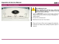
1
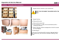
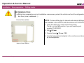
Operation & Service Manual INSTALLATION Carrier Transicold Europe 01/02/07 Neos 100 - Installation/RevA #1/33 Operation & Service Manual INSTALLATION Table of content Introduction...................................................................................................................................................................................4 Preparation before installation....................................................................................................................................................5 Vehicle partition .......................................................................................................................................................................................................... 6 Box preparation ............................................................................................................................................................................7 Drilling inside .............................................................................................................................................................................................................. 7 Drilling outside ............................................................................................................................................................................................................ 9 Waterproof gasket .................................................................................................................................................................................................... 10 Condenser opening.....................................................................................................................................................................................................................10 Condenser fan opening...............................................................................................................................................................................................................11 Roof preparation.........................................................................................................................................................................12 Rivnuts...................................................................................................................................................................................................................... 12 Front supports / Snaplocks ....................................................................................................................................................................................... 13 Rear support ............................................................................................................................................................................................................. 14 Unit...............................................................................................................................................................................................15 Preparation ............................................................................................................................................................................................................... 15 Handling.................................................................................................................................................................................................................... 16 Pod installation ...........................................................................................................................................................................20 Roof skin installation .................................................................................................................................................................21 Driver cab preparation ...............................................................................................................................................................22 Cab command harness fitting ...................................................................................................................................................23 Battery harness fitting................................................................................................................................................................25 Carrier Transicold Europe 01/02/07 Neos 100 - Installation/RevA #2/33 Operation & Service Manual INSTALLATION Table of content Standby module installation ......................................................................................................................................................29 Standby module connection......................................................................................................................................................30 Standby plug installation ...........................................................................................................................................................32 Standby plug connection...........................................................................................................................................................33 Carrier Transicold Europe 01/02/07 Neos 100 - Installation/RevA #3/33 Operation & Service Manual Installation Introduction This document gives the correct rules to follow in order to correctly install the NEOS 100 unit. SAFETY FIRST THE UNIT IS FACTORY CHARGED AND SET. MANDATORY BEFORE ANY ELECTRICAL OPERATION: DISCONNECT THE VEHICLE BATTERY: - First remove the battery ground (-) - then remove the positive battery (+) PERSONAL PROTECTIVE EQUIPMENT Always use adequate personal protective equipment before doing anything on this refrigerant unit. BODYBUILDER RECOMMENDATIONS Carrier Transicold Europe Roof insulation should be MINIMUM 60 mm thickness. Roof insulation should be FLAT. Unit reinforcement should be INSIDE the insulation. DO NOT cut van reinforcement. 01/02/07 Neos 100 - Installation/RevA #4/33 Operation & Service Manual Installation Preparation before installation 1. Unpack the box contents in your warehouse. KEEP THE DOCUMENT DELIVERED WITH THE UNIT ! 2. Unpack the box. Remove the cover. Remove the carton belt. The condenser is ready to be moved directly with a forklift from the box. 3. Check if the box content corresponds to the bill of material on the packaging. Mounting kit In the event of any abnormality (missing, damaged part or part number etc), fill in the form "Advance Warning, DOA, Claim" Carrier Transicold Europe 01/02/07 Neos 100 - Installation/RevA #5/33 Operation & Service Manual Installation Preparation before installation Vehicle partition Take care not to obstruct the air intakes on the evaporator section and the ventilation ducts. For any mobile partition installation, contact our Technical Department or refer to the following chart: MODELS X Y NEOS 100 500 mm 120 mm Insulation and roof opening has to be done by the bodybuilder according to the bodybuilder drawing. Reinforcement fixations have to be inside the insulation; if not: noise transmission through the vehicle body may be experienced. Insulation between the roof and box insulation can be done: - with bodybuilder preparation - using gasket supplied with the unit. Carrier Transicold Europe 01/02/07 Neos 100 - Installation/RevA #6/33 Operation & Service Manual Installation Box preparation Drilling inside RECOMMENDATIONS Before box preparation and unit installation commences, protect the vehicle roof and the refrigeration box floor (cover, cardboard…). Front of the vehicle NOTE: The two drilling jigs for internal and external drillings are available in the same kit with the reference 07-60108-00. 1. Using the drilling jig, mark out the fixing holes. The jig is in the right position if you can read the part number 07-60108-00. 2. Drill ∅ 8,5 mm 3. Female thread ∅ 10 mm / 150 4. Use the fixing material adapted to the reinforcement done by the bodybuilder. Rear of the vehicle Carrier Transicold Europe 01/02/07 Neos 100 - Installation/RevA #7/33 Operation & Service Manual Installation Box preparation Drilling inside NOTE Check that the body builder has installed the front panel with an integrated channel. If not, follow steps 5 & 6. 5. Drill the electrical harness hole (upper position) ∅ 50. - 350 mm from the right front fixing point of the condenser - 30 mm from the roof insulation 6. Drill the drain water hose hole (lower position) ∅ 50 with an angle of 45°. - 360 mm from the right front fixing point of the condenser - 350 mm from the roof insulation Carrier Transicold Europe 01/02/07 Neos 100 - Installation/RevA #8/33 Operation & Service Manual Installation Box preparation Drilling outside Front of the vehicle 7. Mark the 10 fixing holes for the roof skin brackets with the drilling jig (delivered in set P/N: 07-60108-00). The right position of jig is done with regard to condenser opening. The part number 07-60108-00 must be readable. 8. Drill the roof at ∅ 9,5 mm. 9. Clean the roof before following next steps. Rear of the vehicle Carrier Transicold Europe 01/02/07 Neos 100 - Installation/RevA #9/33 Operation & Service Manual Installation Box preparation Waterproof gasket Condenser opening 1. Install the waterproof gasket between the insulation and the roof opening. NOTE : Gasket installation MUST be done as follow: A - Condenser opening Example for van without reinforcement Cut 2 bands at 590 mm for hole length Cut 2 bands at 206 mm for the hole width With remnants: 4 bands for the internal edges. RECOMMENDATIONS Gasket installation: ALWAYS start with the roof by putting the gasket in place. Overlap minimum 5 mm Example for van with reinforcement Carrier Transicold Europe 01/02/07 Neos 100 - Installation/RevA #10/33 Operation & Service Manual Installation Box preparation Waterproof gasket Condenser fan opening B – Condenser fan opening Cut 4 bands at 315 mm With remnants: complete the internal edges insulation.. RECOMMENDATIONS Carrier Transicold Europe 01/02/07 Gasket installation: ALWAYS start with the ceiling by putting the gasket in place. Overlap minimum 5 mm Neos 100 - Installation/RevA #11/33 Operation & Service Manual Installation Roof preparation Rivnuts 1. To install the rivnuts (10): Put silicone in the holes Insert the rivnuts using the adapted tool (manual or pneumatic). Remove excess of silicone with adapted cleaning solution. NOTE : To remove the rivnut: - Drill the rivnut head with a drill ∅ 10,5 mm to remove it. - After rivnut head removal, put a drift punch in replacement of the head. - Using a hammer punch the rivnut back side. - Check the drilling hole to be sure the hexagonal punching is not damaged in order to be able to put in place a new rivnut. Carrier Transicold Europe 01/02/07 Neos 100 - Installation/RevA #12/33 Operation & Service Manual Installation Roof preparation Front supports / Snaplocks 2. Install the 3 fixing front supports of the skin. RECOMMENDATIONS Put grease on each fixation screw before installation to avoid rust. 3. Install the 2 rear snaplocks. RECOMMENDATIONS Put grease on each fixation screw before installation to avoid rust. Carrier Transicold Europe 01/02/07 Neos 100 - Installation/RevA #13/33 Operation & Service Manual Installation Roof preparation Rear support 4. Install the safety rear support. RECOMMENDATIONS Put grease on each fixation screw before installation to avoid rust. Carrier Transicold Europe 01/02/07 Neos 100 - Installation/RevA #14/33 Operation & Service Manual Installation Unit Preparation 1. To be done first: Remove the cable bushing fixing screw. 2. Place the lifting tool inside the vehicle (P/N: 07-60109-00) RECOMMENDATIONS 2 technicians are recommended to place the lifting tool in the vehicle. Carrier Transicold Europe 01/02/07 Neos 100 - Installation/RevA #15/33 Operation & Service Manual Installation Unit Handling 1. Using a forklift, place the condenser section onto the lifting tool inside the vehicle body. 2. Run the electrical harness up through the upper hole. Carrier Transicold Europe 01/02/07 Neos 100 - Installation/RevA #16/33 Operation & Service Manual Installation Unit Handling 3. Line up the unit with the fixing holes. RECOMMENDATIONS While lifting up the unit, take care of the condenser introduction to not damage the gasket insulation 4. Fix the unit with the 6 screws (BTR 10x50) Carrier Transicold Europe 01/02/07 Neos 100 - Installation/RevA #17/33 Operation & Service Manual Installation Unit Installation 1. Replace the cable bushing screw: Remove the 3 mounting screws of the electrical motor. Swing out the electric motor and remove the belt to gain access to the cable bushing screw. Re-install the cable bushing screw. Re-install the electric motor belt and the motor to its original position. Check the belt alignment and tension (refer to belt alignment section) NOTE: Belt tension is done automatically when the electrical motor bracket is re-installed. Carrier Transicold Europe 01/02/07 Neos 100 - Installation/RevA #18/33 Operation & Service Manual Installation Unit Installation 2. Insulate the harness hole (silicone, polyurethane, mastic…). 3. Run the drain water hose through the lower hole. Carrier Transicold Europe 01/02/07 Neos 100 - Installation/RevA #19/33 Operation & Service Manual Installation Pod installation 4. Install the isotherm pod : 5 locking screws 5. Connect the water drain hose on the pod water drain plug. 6. Insulate the drain water hose hole (silicone, polyurethane, mastic…) 7. Install the Serial Number sticker on the pod (delivered in mounting kit – Qty 2). Carrier Transicold Europe 01/02/07 Neos 100 - Installation/RevA #20/33 Operation & Service Manual Installation Roof skin installation RECOMMENDATIONS Before installing the roof top cover, make sure that the distance between the middle hook and each side hook is 425 mm. 1. Install a LUBRICANT onto the 3 front hooks to allow the fitting of the top cover without moving or damaging the rubber bushes. 2. Connect the condenser fan. 3. Slide the skin onto the 3 front hooks. 4. Press on the rear of the cover to engage the snaplocks. 5. Install the rear safety screw, adding the plastic spacer if required. Carrier Transicold Europe 01/02/07 Neos 100 - Installation/RevA #21/33 Operation & Service Manual Installation Driver cab preparation RECOMMENDATIONS Before drilling the floor, check the location of fuel tank, harness and/or tubes. 1. Drill a hole in the cab floor (behind driver or passenger seat – depends on battery location). RECOMMENDATIONS Protect the hole (ex: armoured hose) to avoid harness damage. 2. Run water drain hose through the floor. 3. Run battery cable through the floor (keep a wire loop for a potential standby module installation.) 4. Run the cab command and ignition cable to the dashboard (keep a wire loop for a potential standby module installation.) 5. Install the standby module for unit so equipped – refer to "Standby module installation" - p29. 6. Install a capping (not supplied) to cover the hoses and harness. 7. Insulate the water drain hose. Carrier Transicold Europe 01/02/07 Neos 100 - Installation/RevA #22/33 Operation & Service Manual Installation Cab command harness fitting NOTE: For cab command harness fitting, refer to the vehicle mounting kit instructions. 1. Route the cab command harness to the vehicle dashboard. RECOMMENDATIONS Carrier Transicold Europe 01/02/07 Protect or move the harness away from metallic corners of the chassis. Avoid connecting the harness to/or in contact with heating source. Avoid connecting the harness to parts that may cause vibrations. Neos 100 - Installation/RevA #23/33 Operation & Service Manual Installation Cab command harness fitting 2. Fit the cab command (in specified location). RECOMMENDATIONS Take care not to pierce any harness or hoses within the dashboard. If the cab command is built into the dashboard, fit it as far as possible from the heating ducts. Maximum temperature of exposure: 70°C (158°F) The cab command MUST NOT be located behind the screen (T° too high and obstruction of windscreen). 3. Route the ignition cable (white) to the vehicle fuse box. 4. Connect the white wire onto the fuse holder supplied in the mounting kit (2A). 5. Refer to the corresponding mounting kit instruction to connect the +12Vdc ignition live. Carrier Transicold Europe 01/02/07 Neos 100 - Installation/RevA #24/33 Operation & Service Manual Installation Battery harness fitting MANDATORY BEFORE ANY ELECTRICAL OPERATION. DISCONNECT THE VEHICLE BATTERY: Remove the battery ground (-), the positive battery (+) and lock-out. 1. Route the battery harness to the vehicle battery. 2. Secure the harness to the vehicle chassis using plastic tiewraps. RECOMMENDATIONS Carrier Transicold Europe 01/02/07 Protect or move the harness away from metallic corners of the chassis. Avoid connecting the harness to/or in contact with heating source. Avoid connecting the harness to parts that may cause vibrations. Do not secure the unit harness to the vehicle harness or piping Avoid drilling the vehicle frame. Neos 100 - Installation/RevA #25/33 Operation & Service Manual Installation Battery harness fitting 3. Cut the battery harness coming from the unit or standby module (if equipped) to the required length. 4. Strip the + battery (35mm2 red) and the fuse holder for the + microprocessor positive. 5. Using a crimping tool, install the (125A) fuse supplied with the mounting kit. NOTE : Soft-solder is recommended. Carrier Transicold Europe 01/02/07 Neos 100 - Installation/RevA #26/33 Operation & Service Manual Installation Battery harness fitting 6. Heat the retractable sleeve to insulate the connector. 7. Connect the + battery to the battery. 8. Strip the battery ground (-) (35mm2 black) – crimp the terminal with the adapted crimping tool. NOTE : Soft-solder is recommended. 9. Connect the + microprocessor (1,5mm2 red) to the fuse holder (2A) – crimp the terminal with the adapted crimping tool. 10. Heat the retractable connection. Carrier Transicold Europe 01/02/07 Neos 100 - Installation/RevA #27/33 Operation & Service Manual Installation Battery harness fitting 11. Put the fuse in place (2 amps). 12. Connect unit ground (-) to the battery. 13. Re-connect the ground (-) of the vehicle battery. 14. Start the vehicle and press the cab command ON key to start the unit. REMINDER : This unit is factory charged and set. Carrier Transicold Europe 01/02/07 Neos 100 - Installation/RevA #28/33 Operation & Service Manual Installation Standby module installation NOTE The standby module can be fit under or behind the seat. Before drilling the floor, check the location of fuel tank, harness and/or tubes. 1. Put in place the module and mark the 4 fixing holes for the standby module. 2. Drill at ∅ 9,5 mm. 3. Install the 4 rivnuts. 4. Fix the module. Carrier Transicold Europe 01/02/07 Neos 100 - Installation/RevA #29/33 Operation & Service Manual Installation Standby module connection 1. Cut to the required length: the + battery (red 35mm2), the – battery (black 35mm2) and the ignition cable (white 1,5 mm2) coming from the unit. 2. Battery cable from unit Strip the + and – battery. Crimp the ring terminals with the adapted crimping tool (+ battery ∅ 6 mm and – battery ∅ 8mm). Tighten the + battery at 4 Nm and – battery at 10 Nm. Cover screws and ring terminals with heat shrink tube. 3. Ignition cable from unit Carrier Transicold Europe 01/02/07 Strip the wire. Crimp the terminals with the adapted crimping tool. Connect the wire into the "Ignition key out" port. Neos 100 - Installation/RevA #30/33 Operation & Service Manual Installation Standby module connection 4. Battery cable from standby module to the battery Strip the + and – battery. Crimp the ring terminals with the adapted crimping tool (∅ 8mm). Tighten the 2 wires at 10 Nm. Cover screws and ring terminals with heat shrink tube. 5. Ignition key to the standby module Carrier Transicold Europe 01/02/07 Strip the wire Crimp the terminals with the adapted crimping tool. Connect the wire into the "Ignition key in" port. Neos 100 - Installation/RevA #31/33 Operation & Service Manual Installation Standby plug installation RECOMMANDATIONS Make sure there is a room at the rear for the cable and enough room for the fastening nut. Before drilling the bumper, check the location of harness, components and/or tubes. Protect the hole (ex: armoured hose) to avoid harness damage. Protect or move the harness away from metallic corners of the chassis. Avoid connecting the harness to/or in contact with heating source. Avoid connecting the harness to parts that may cause vibrations. 1. To Install the standby plug : Carrier Transicold Europe 01/02/07 Drill the front bumper ∅ 25 mm. Install the plug with the fastened nut. Neos 100 - Installation/RevA #32/33 Operation & Service Manual Installation Standby plug connection 2. Run the cable to the standby module into the driver cab. 3. Connect the standby module: Strip the phase (brown) and neutral (black) wires Crimp the terminals with adapted crimping tool. Heat the heat shrink tube. Strip the ground (yellow/green). Crimp the ring terminal with the adapted crimping tool. Heat the heat shrink tube. Install the connector and tighten the nut. 4. Secure the standby cable onto the standby module with plastic tie-wraps. 5. Secure all wires together with plastic tie-wraps. 6. Continue the installation: refer to "Driver cab preparation" – step 4 - p22 Carrier Transicold Europe 01/02/07 Neos 100 - Installation/RevA #33/33