1
Sun Fire™ V215 and V245 Servers
Service Manual
Sun Microsystems, Inc.
www.sun.com
Part No. 819-3038-10
September 2006, Revision A
Submit comments about this document at: http://www.sun.com/hwdocs/feedback
Copyright 2006 Sun Microsystems, Inc., 4150 Network Circle, Santa Clara, California 95054, U.S.A. All rights reserved.
Sun Microsystems, Inc. has intellectual property rights relating to technology that is described in this document. In particular, and without
limitation, these intellectual property rights may include one or more of the U.S. patents listed at http://www.sun.com/patents and one or
more additional patents or pending patent applications in the U.S. and in other countries.
This document and the product to which it pertains are distributed under licenses restricting their use, copying, distribution, and
decompilation. No part of the product or of this document may be reproduced in any form by any means without prior written authorization of
Sun and its licensors, if any.
Third-party software, including font technology, is copyrighted and licensed from Sun suppliers.
Parts of the product may be derived from Berkeley BSD systems, licensed from the University of California. UNIX is a registered trademark in
the U.S. and in other countries, exclusively licensed through X/Open Company, Ltd.
Sun, Sun Microsystems, the Sun logo, AnswerBook2, docs.sun.com, Sun Fire, and Solaris are trademarks or registered trademarks of Sun
Microsystems, Inc. in the U.S. and in other countries.
All SPARC trademarks are used under license and are trademarks or registered trademarks of SPARC International, Inc. in the U.S. and in other
countries. Products bearing SPARC trademarks are based upon an architecture developed by Sun Microsystems, Inc.
The OPEN LOOK and Sun™ Graphical User Interface was developed by Sun Microsystems, Inc. for its users and licensees. Sun acknowledges
the pioneering efforts of Xerox in researching and developing the concept of visual or graphical user interfaces for the computer industry. Sun
holds a non-exclusive license from Xerox to the Xerox Graphical User Interface, which license also covers Sun’s licensees who implement OPEN
LOOK GUIs and otherwise comply with Sun’s written license agreements.
U.S. Government Rights—Commercial use. Government users are subject to the Sun Microsystems, Inc. standard license agreement and
applicable provisions of the FAR and its supplements.
DOCUMENTATION IS PROVIDED "AS IS" AND ALL EXPRESS OR IMPLIED CONDITIONS, REPRESENTATIONS AND WARRANTIES,
INCLUDING ANY IMPLIED WARRANTY OF MERCHANTABILITY, FITNESS FOR A PARTICULAR PURPOSE OR NON-INFRINGEMENT,
ARE DISCLAIMED, EXCEPT TO THE EXTENT THAT SUCH DISCLAIMERS ARE HELD TO BE LEGALLY INVALID.
Copyright 2006 Sun Microsystems, Inc., 4150 Network Circle, Santa Clara, Californie 95054, Etats-Unis. Tous droits réservés.
Sun Microsystems, Inc. a les droits de propriété intellectuels relatants à la technologie qui est décrit dans ce document. En particulier, et sans la
limitation, ces droits de propriété intellectuels peuvent inclure un ou plus des brevets américains énumérés à http://www.sun.com/patents et
un ou les brevets plus supplémentaires ou les applications de brevet en attente dans les Etats-Unis et dans les autres pays.
Ce produit ou document est protégé par un copyright et distribué avec des licences qui en restreignent l’utilisation, la copie, la distribution, et la
décompilation. Aucune partie de ce produit ou document ne peut être reproduite sous aucune forme, par quelque moyen que ce soit, sans
l’autorisation préalable et écrite de Sun et de ses bailleurs de licence, s’il y ena.
Le logiciel détenu par des tiers, et qui comprend la technologie relative aux polices de caractères, est protégé par un copyright et licencié par des
fournisseurs de Sun.
Des parties de ce produit pourront être dérivées des systèmes Berkeley BSD licenciés par l’Université de Californie. UNIX est une marque
déposée aux Etats-Unis et dans d’autres pays et licenciée exclusivement par X/Open Company, Ltd.
Sun, Sun Microsystems, le logo Sun, AnswerBook2, docs.sun.com, Sun Fire, et Solaris sont des marques de fabrique ou des marques déposées
de Sun Microsystems, Inc. aux Etats-Unis et dans d’autres pays.
Toutes les marques SPARC sont utilisées sous licence et sont des marques de fabrique ou des marques déposées de SPARC International, Inc.
aux Etats-Unis et dans d’autres pays. Les produits portant les marques SPARC sont basés sur une architecture développée par Sun
Microsystems, Inc.
L’interface d’utilisation graphique OPEN LOOK et Sun™ a été développée par Sun Microsystems, Inc. pour ses utilisateurs et licenciés. Sun
reconnaît les efforts de pionniers de Xerox pour la recherche et le développement du concept des interfaces d’utilisation visuelle ou graphique
pour l’industrie de l’informatique. Sun détient une license non exclusive de Xerox sur l’interface d’utilisation graphique Xerox, cette licence
couvrant également les licenciées de Sun qui mettent en place l’interface d ’utilisation graphique OPEN LOOK et qui en outre se conforment
aux licences écrites de Sun.
LA DOCUMENTATION EST FOURNIE "EN L’ÉTAT" ET TOUTES AUTRES CONDITIONS, DECLARATIONS ET GARANTIES EXPRESSES
OU TACITES SONT FORMELLEMENT EXCLUES, DANS LA MESURE AUTORISEE PAR LA LOI APPLICABLE, Y COMPRIS NOTAMMENT
TOUTE GARANTIE IMPLICITE RELATIVE A LA QUALITE MARCHANDE, A L’APTITUDE A UNE UTILISATION PARTICULIERE OU A
L’ABSENCE DE CONTREFAÇON.
Please
Recycle
Contents
Preface
1.
xv
Diagnosing Server Performance and Faults
1.1
Overview of Diagnostic Tools
1.2
Choosing a Fault Isolation Tool
1.3
POST Diagnostics
1.4
1–2
1–3
1–6
1.3.1
Starting POST Diagnostics
1.3.2
Controlling POST Diagnostics
OpenBoot Diagnostics
1–6
1–7
1–9
1.4.1
Starting OpenBoot Diagnostics
1.4.2
Controlling OpenBoot Diagnostics Tests
1.4.3
1.5
1–1
1–9
1–9
1.4.2.1
test and test-all Commands
1.4.2.2
What OpenBoot Diagnostics Error Messages Tell You
1–11
OpenBoot Diagnostic Commands
1–10
1–12
1.4.3.1
probe-scsi and probe-scsi-all Commands
1.4.3.2
probe-ide Command
1–13
1.4.3.3
show-devs Command
1–14
1.4.3.4
Running OpenBoot Commands
Operating System Diagnostic Tools
1–12
1–15
1–15
iii
1.6
1.5.1
Error and System Message Log Files
1.5.2
Solaris System Information Commands
2.
1–16
1.5.2.2
prtdiag Command
1–16
1.5.2.3
prtfru Command
1.5.2.4
psrinfo Command
1–17
1.5.2.5
showrev Command
1–17
1–15
1–17
1–18
Viewing Recent Test Results
1–18
Additional Diagnostic Tests for Specific Devices
1–18
1.7.1
Confirming That the Internal Hard Drives are Active
1.7.2
Confirming That the External Hard Drives Are Active
1.7.3
Confirming That the DVD Super-Multi Drive is Connected
1.7.4
Checking Network Connections on the Primary Network
1.7.5
Checking Network Connections on Additional Network
Interfaces 1–22
Replacing Hot-Pluggable and Hot-Swappable CRUs
2–1
2.1
Devices That are Hot-Pluggable or Hot-Swappable
2.2
Hot-Plugging a Hard Drive
2.3
2.4
2.5
iv
prtconf Command
Recent Diagnostic Test Results
1.6.1
1.7
1.5.2.1
1–15
2–2
2.2.1
Removing a Hard Drive
2.2.2
Installing a Hard Drive
Hot-Swapping a Fan Tray
2–3
2–5
2–7
2.3.1
Removing a Fan Tray
2–8
2.3.2
Installing a Fan Tray
2–10
Hot-Swapping a Hard Drive Fan Tray
2–11
2.4.1
Removing a Hard Drive Fan Tray
2.4.2
Installing a Hard Drive Fan Tray
Hot-Swapping a Power Supply
2–13
Sun Fire V215 and V245 Servers Service Guide • September 2006
2–11
2–12
2–2
1–19
1–20
1–20
1–21
3.
2.5.1
Removing a Power Supply
2.5.2
Installing a Power Supply
Replacing Cold-Swappable FRUs
3.1
3.2
3.3
Safety Information
2–13
2–15
3–1
3–2
3.1.1
Safety Symbols
3–2
3.1.2
Electrostatic Discharge Safety Measures
3–3
3.1.2.1
Using an Antistatic Wrist Strap
3.1.2.2
Using an Antistatic Mat
Procedures for Parts Replacement
3–3
3–3
3–3
3.2.1
Required Tools
3–4
3.2.2
Powering Off the Server – ALOM Command Line
3.2.3
Powering Off the Server – Graceful Shutdown
3.2.4
Powering Off the Server – Emergency Shutdown
3.2.5
Extending the Server to the Maintenance Position – Rackmounted
Servers Only 3–5
3.2.6
Removing a Server From the Rack
3.2.7
Performing Electrostatic Discharge – Antistatic Prevention
Measures 3–9
3.2.8
Removing Power From the Server
3.2.9
Removing the Rear Cover
3.2.10
Removing the Bezel
3.2.11
Removing the Front Cover
3.2.12
(Sun Fire V245) Removing the Air Baffle
3.2.13
(Sun Fire V245) Installing the Air Baffle
3–4
3–5
3–5
3–7
3–10
3–10
3–11
Removing and Installing FRUs
3–13
3–13
3–14
3–15
3.3.1
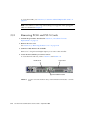
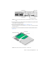
Removing PCI-E and PCI-X Cards
3–16
3.3.2
Installing PCI-E or PCI-X Cards
3.3.3
Removing PCI-E and PCI-X Riser Boards
3.3.4
Installing PCI-E or PCI-X Riser Boards
3–18
3–19
3–21
Contents
v
3.4
vi
3.3.5
Removing DIMMs
3–22
3.3.6
Installing DIMMs
3.3.7
Removing the Motherboard Assembly
3.3.8
Installing the Motherboard Assembly
3.3.9
Removing the Power Distribution Board
3.3.10
Installing the Power Distribution Board
3.3.11
Removing the Front Indicator Board
3.3.12
Installing the Front Indicator Board
3.3.13
Removing the Fan Tray Connector Boards
3.3.14
Installing the Fan Tray Connector Boards
3.3.15
Removing the Front I/O Board
3.3.16
Installing the Front I/O Board
3.3.17
Removing the DVD Super-Multi Drive
3.3.18
Installing the DVD Super-Multi Drive
3.3.19
Removing the Hard Drive Backplane
3.3.20
Installing the Hard Drive Backplane
3.3.21
Removing the Hard Drive Fan Tray
3.3.22
Installing the Hard Drive Fan Tray
3.3.23
(Sun Fire V245) Removing the Hard Drive Fan Tray Connector
Board 3–53
3.3.24
(Sun Fire V245) Installing the Hard Drive Fan Tray Connector
Board 3–54
3.3.25
Removing the Battery
3.3.26
Installing the Battery
3.3.27
Removing NVRAM
3.3.28
Installing NVRAM
3–25
Procedures for Finishing Up
3–27
3–34
3–36
3–39
3–40
3–41
3–44
3–45
3–46
3–47
3–49
3–50
3–52
3–56
3–57
3–58
3–58
3.4.1
Installing the Front Cover and Bezel
3.4.2
Installing the Rear Cover
Sun Fire V215 and V245 Servers Service Guide • September 2006
3–43
3–43
3–55
3–60
3–42
3–58
3.4.3
Reinstalling the Server in the Rack
3.4.4
Returning the Server to the Normal Rack Position
3.4.5
Applying Power to the Server
A. DIMM and PCI Card Guidelines
DIMM Guidelines
A.2
PCI-E and PCI-X Card Guidelines
3–64
A–1
B. Customer and Field Replaceable Units
Index
3–62
A–1
A.1
B.1
3–61
A–3
B–1
Customer and Field Replaceable Units
B–1
Index–1
Contents
vii
viii
Sun Fire V215 and V245 Servers Service Guide • September 2006
Figures
FIGURE 1-1
Choosing a Tool to Isolate Hardware Faults
1–5
FIGURE 2-1
Locating the Hard Drive Release Button and Latch
FIGURE 2-2
Removing a Fan Tray
FIGURE 2-3
Top Fan, System Required Indicator, Locator Indicators, and Locator Button
FIGURE 2-4
Failure and Service Required Indicators
FIGURE 2-5
Hard Drive Fan Tray – Sun Fire V245 Server
FIGURE 2-6
Location of the Power Supplies and Release Latches
FIGURE 2-7
Rotating the Cable Management Arm to Access the Server Power Supplies
FIGURE 3-1
Locator Indicator/Locator Button
FIGURE 3-2
Slide Release Latches
FIGURE 3-3
Metal Lever and Cable Management Arm
FIGURE 3-4
Release Tabs and Slide Assembly
FIGURE 3-5
Removing the Rear Cover
FIGURE 3-6
Front Cover, Front Cover Door, and Latch – Sun Fire V245
FIGURE 3-7
Removing the Bezel From the Server – Sun Fire V245
FIGURE 3-8
Air Baffle, Guide Pins, and Handle – Sun Fire V245
FIGURE 3-9
Location of PCI-E and PCI-X Slots, and PCI Hold-Down Bracket – Sun Fire V215
3–16
FIGURE 3-10
Location of PCI-E and PCI-X Slots, and PCI Hold-Down Bracket – Sun Fire V245
3–17
FIGURE 3-11
Riser Board and PCI Card Connector – Sun Fire V215
FIGURE 3-12
Installing a PCI Long Card – Sun Fire V245
2–4
2–9
2–10
2–10
2–12
2–14
2–15
3–6
3–7
3–8
3–9
3–11
3–12
3–12
3–14
3–17
3–19
ix
FIGURE 3-13
Riser Boards and PCI Option Cards – Sun Fire V215
FIGURE 3-14
PCI-E and PCI-X Riser Boards
FIGURE 3-15
Removing the Air Baffle – Sun Fire V215
FIGURE 3-16
Removing DIMMs
FIGURE 3-17
Motherboard Assembly
FIGURE 3-18
PCI-X and PCI-E Riser Boards – Sun Fire V215
FIGURE 3-19
PCI-X Riser Board Standoff – Sun Fire V215
FIGURE 3-20
Motherboard to Front I/O Board Cable
FIGURE 3-21
Upper and Lower Cable Retainers and Motherboard/SAS Backplane Cable
FIGURE 3-22
Removing the Motherboard Assembly Screws
FIGURE 3-23
Removing the Motherboard Assembly From the Chassis
FIGURE 3-24
Installing the Motherboard Assembly
FIGURE 3-25
Power Supply Release Latches – Sun Fire V245
FIGURE 3-26
Motherboard/SAS Backplane Cable Routing
FIGURE 3-27
Removing the Power Distribution Board
FIGURE 3-28
Removing the Front Indicator Board
FIGURE 3-29
Removing the Fan Tray Connector Board
FIGURE 3-30
Removing the Front I/O Board
FIGURE 3-31
Upper Cable Retainer, Motherboard/SAS Backplane Cable, DVD Super-Multi Drive, and
Spring Latch 3–46
FIGURE 3-32
Removing the Hard Drive Backplane – Sun Fire V215
3–48
FIGURE 3-33
Removing the Hard Drive Backplane – Sun Fire V245
3–49
FIGURE 3-34
Opening the Rear Cover Door – Sun Fire V245
FIGURE 3-35
Hard Drive Fan Tray – Sun Fire V245
FIGURE 3-36
Hard Drive Fan Tray Cage and Screws
FIGURE 3-37
Hard Drive Fan Tray Connector Board – Connector J1
FIGURE 3-38
Removing the Battery
FIGURE 3-39
Removing NVRAM
3–57
FIGURE 3-40
Installing the Bezel
3–59
FIGURE 3-41
Installing the Front Cover – Sun Fire V245 Server
x
3–20
3–21
3–24
3–25
3–28
3–29
3–30
3–31
3–32
3–33
3–34
3–35
3–37
3–38
3–39
3–41
3–42
3–44
3–51
3–52
3–53
3–54
3–56
Sun Fire V215 and V245 Servers Service Guide • September 2006
3–60
FIGURE 3-42
Installing the Rear Cover – Sun Fire V215 server
3–61
FIGURE 3-43
Returning the Server to the Rack
FIGURE 3-44
Release Tabs – Rails
FIGURE 3-45
Installing the Cable Management Arm (CMA)
FIGURE A-1
DIMM Layout A–2
FIGURE B-1
Customer and Field-Replaceable Units, Part 1 of 2
B–2
FIGURE B-2
Customer and Field-Replaceable Units, Part 2 of 2
B–3
3–62
3–63
3–64
Figures
xi
xii
Sun Fire V215 and V245 Servers Service Guide • September 2006
Tables
TABLE 1-1
Summary of Diagnostic Tools
1–2
TABLE 1-2
OpenBoot Configuration Variables
TABLE 1-3
Keywords for the test-args OpenBoot Configuration Variable
TABLE 2-1
Sample Ap_id Output
2–3
TABLE 2-2
Sample Ap_id Output
2–6
TABLE 2-3
Sample Ap_id Output
2–7
TABLE 3-1
DIMM Names, Connectors, and Locations
TABLE A-1
DIMM Name, DIMM Number, and DIMM Connector
TABLE A-2
Sun Fire V215 and V245 Servers PCI-E and PCI-X Configurations
TABLE B-1
Sun Fire V215 and V245 Servers – CRU and FRU List
1–7
1–10
3–22
A–2
A–3
B–4
xiii
xiv
Sun Fire V215 and V245 Servers Service Guide • September 2006
Preface
Use Sun Fire V215 and V245 Servers Service Manual as an aid for diagnosing problems
and replacing components within the Sun Fire V215 and V245 servers.
This document is written for technicians, service personnel, and system
administrators who service and repair computer systems. The person qualified to
use this document:
■
■
■
■
Can open a system chassis and identify and replace internal components.
Understands the Solaris™ Operating System and the command-line interface.
Has superuser privileges for the system being serviced.
Understands typical hardware troubleshooting tasks.
Before You Read This Document
This document does not cover the following topics:
■
Server overview information
For information about hardware and software features such as front and rear
panels, status indicators, cable connections, and environmental requirements,
refer to the Sun Fire V215 and V245 Servers Getting Started Guide.
■
Installation and rackmounting
For detailed information about installation and rackmounting, refer to the Sun
Fire V215 and V245 Servers Installation Guide.
■
General administrative tasks
For detailed information about administrative tasks, refer to the Sun Fire V215 and
V245 Servers Administration Guide.
Before following any of the procedures described in this document, ensure that you
have read the Sun Fire V215 and V245 Servers Compliance and Safety Manual.
xv
How This Document Is Organized
This guide is organized into the following chapters:
Chapter 1 describes the diagnostics tools available for use with the Sun Fire V215
and V245 servers.
Chapter 2 explains how to replace hot-swappable and hot-pluggable customer
replaceable units (CRUs).
Chapter 3 describes how to replace field replacable units (FRUs) that are coldswappable.
Appendix A explains how to configure DIMMs, PCI-E and PCI-X cards for your
server.
Appendix B describes the location customer and field replacable units within the
Sun Fire V215 and V245 Servers.
Using UNIX Commands
This document does not contain information on basic UNIX® commands and
procedures such as shutting down the server, booting the server, and configuring
devices.
Refer to one or more of the following documents for this information:
■
Solaris 10 Sun Hardware Platform Guide (817-6337)
■
Solaris Operating System documentation, which is at:
http://docs.sun.com
■
Other software documentation that you received with your server
xvi Sun Fire V215 and V245 Servers Service Guide • September 2006
Typographic Conventions
Typeface*
Meaning
Examples
AaBbCc123
The names of commands, files,
and directories; on-screen
computer output
Edit your.login file.
Use ls -a to list all files.
% You have mail.
AaBbCc123
What you type, when contrasted
with on-screen computer output
% su
Password:
AaBbCc123
Document titles, new words or
terms, words to be emphasized.
Replace command-line variables
with real names or values.
Read Chapter 6 in the User’s Guide.
These are called class options.
You must be superuser to do this.
To delete a file, type rm filename.
* The settings on your browser might differ from these settings.
Shell Prompts
Shell
Prompt
C shell
machine-name%
C shell superuser
machine-name#
Bourne shell and Korn shell
$
Bourne shell and Korn shell superuser
#
Preface
xvii
Related Documentation
You can view and print the following manuals from the Sun documentation web site
at: http://www.sun.com/documentation
Part
Number
Title
Description
Sun Fire V215 and V245 Servers
Product Notes
Late-breaking information about the
servers
819-3040
Sun Fire V215 and V245 Servers
Getting Started Guide
Information about where to find
documentation to get your server
installed and running quickly
819-3041
Sun Fire V215 and V245 Servers
Installation Guide
Detailed rackmounting, cabling, poweron, and configuration information
819-3037
Sun Fire V215 and V245 Servers
Administration Guide
How to perform administrative tasks that
are specific to the Sun Fire V215 and V245
servers
819-3036
Sun Fire V215 and V245 Servers
Compliance and Safety Manual
Platform specific information about
regulatory compliance, safety agency
compliance, and the Declaration of
Conformity for the Sun Fire V215 and
V245 servers.
819-3039
Read Important Safety Information (816-7190) and the Sun Fire V215 and V245 Servers
Getting Started Guide (819-3039) before performing any of the procedures
documented in this manual.
Third-Party Web Sites
Sun is not responsible for the availability of third-party web sites mentioned in this
document. Sun does not endorse and is not responsible or liable for any content,
advertising, products, or other materials that are available on or through such sites
or resources. Sun will not be responsible or liable for any actual or alleged damage
or loss caused by or in connection with the use of or reliance on any such content,
goods, or services that are available on or through such sites or resources.
xviii
Sun Fire V215 and V245 Servers Service Guide • September 2006
Documentation, Support, and Training
Sun Function
URL
Documentation
http://www.sun.com/documentation/
Support
http://www.sun.com/support/
Training
http://www.sun.com/training/
Sun Welcomes Your Comments
Sun is interested in improving its documentation and welcomes your comments and
suggestions. You can submit your comments by going to:
http://www.sun.com/hwdocs/feedback
Please include the title and part number of your document with your feedback:
Sun Fire V215 and V245 Servers Service Guide, part number 819-3038-10
Preface
xix
xx
Sun Fire V215 and V245 Servers Service Guide • September 2006
CHAPTER
1
Diagnosing Server Performance and
Faults
This chapter describes the diagnostic tools available for use with the Sun Fire V215
and V245 servers. This chapter contains the following diagnostic sections:
■
■
■
■
■
■
■
Section 1.1,
Section 1.2,
Section 1.3,
Section 1.4,
Section 1.5,
Section 1.6,
Section 1.7,
“Overview of Diagnostic Tools” on page 1-2
“Choosing a Fault Isolation Tool” on page 1-3
“POST Diagnostics” on page 1-6
“OpenBoot Diagnostics” on page 1-9
“Operating System Diagnostic Tools” on page 1-15
“Recent Diagnostic Test Results” on page 1-18
“Additional Diagnostic Tests for Specific Devices” on page 1-18
1-1
1.1
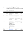
Overview of Diagnostic Tools
Sun provides a range of diagnostic tools for use with the Sun Fire V215 and V245
servers. TABLE 1-1 contains summaries of the diagnostic tools.
TABLE 1-1
Summary of Diagnostic Tools
Remote
Capability
Diagnostic Tool
Type
What It Does
Accessibility and Availability
ALOM
Hardware
and
Software
Monitors environmental
conditions, performs
environmental fault isolation,
and provides remote console
access to system.
Can function on standby
power and without
operating system.
Designed for
remote
system
access
Status
indicators
Hardware
Indicates operational status of the
overall system and subassemblies that have status
indicators.
Accessed from system
chassis. Is available
anytime power is available.
Local, but
operational
status can be
viewed in
ALOM
POST
Firmware
Provides test coverage for CPUs,
CPU caches, system memory,
CPU interconnects, I/O bridges,
and system buses.
Runs automatically on
startup. Is available when
the operating system is not
running.
Local, but
operation
can be
viewed in
ALOM
OpenBoot™
Diagnostics
Firmware
Provides test coverage
specifically on the I/O subsystems and plug-in cards. Test
coverage consists of I/O
channels, boot controllers (SCSI,
IDE, USB, Ethernet), non core
devices (Flash, I2C,
environmental controls,
NVRAM), and plug-in cards with
native Fcode drivers which
support IEEE 1275 self test
mechanisms. OpenBoot
Diagnostics provides Fcode selftests for on-board hardware
devices.
Runs automatically or
interactively. Is available
when the operating system
is not running.
Local, but
operation
can be
viewed in
ALOM
OpenBoot
Diagnostic
commands
Firmware
Displays various system
information (See Section 1.4.3,
“OpenBoot Diagnostic
Commands” on page 1-12)
Available when the
operating system is not
running
Local, but
can be
accessed in
ALOM
1-2
Sun Fire V215 and V245 Servers Service Guide • September 2006
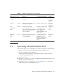
TABLE 1-1
Summary of Diagnostic Tools (Continued)
Remote
Capability
Diagnostic Tool
Type
What It Does
Accessibility and Availability
Solaris OS
commands
Software
Displays various system
information
Requires operating system
Local, but
can be
accessed in
ALOM
SunVTS™
Software
Exercises and stresses the system,
running tests in parallel
Requires operating system.
View and
control over
network
Sun
Management
Center
Software
Monitors both hardware
environmental conditions and
software performance of multiple
machines. Generates alerts for
various conditions
Requires operating system
to be running on both
monitored and master
servers. Requires a
dedicated database on the
master server
Designed for
remote
access
Hardware
Diagnostic
Suite
Software
Exercises an operational system
by running sequential tests. Also
reports failed FRUs
A separately purchased
optional add-on to Sun
Management Center.
Requires operating system
and Sun Management
Center
Designed for
remote
access
1.2
Choosing a Fault Isolation Tool
This section helps you choose the right tool to isolate a failed part in a Sun Fire V215
or V245 server. Consider the following questions when selecting a tool.
1. Have you checked the status indicators?
Certain system components have status indicators that can alert you when a
component requires replacement.
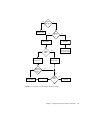
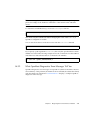
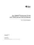
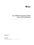
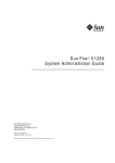
2. Does the server boot?
■
If the server cannot boot, you have to run firmware-based diagnostics that do not
depend on the operating system.
■
If the server can boot, you should use a more comprehensive tool. The typical
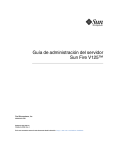
fault isolation process is illustrated in FIGURE 1-1.
Chapter 1
Diagnosing Server Performance and Faults
1-3
3. Do you intend to run the tests remotely?
Sun Management Center, ALOM, and the Hardware Diagnostic Suite software
enable you to run tests from a remote server. ALOM also provides a means of
redirecting system console output, enabling you to remotely view and run tests,
like POST diagnostics, that usually require physical proximity to the serial port
on the back panel.
Note – The SunVTS software also enables you to run tests remotely by using the ttymode through a remote login or a Telnet session.
4. Will the tool test the suspected sources of the problem?
Use a diagnostic tool capable of testing the suspected problem sources. TABLE 1-1
shows which parts can be isolated by each fault isolating tool.
5. Is the problem intermittent or software-related?
If a problem is not caused by a defective hardware component, use a system
exerciser tool rather than a fault isolation tool.
1-4
Sun Fire V215 and V245 Servers Service Guide • September 2006
Fault
indicator lit
?
yes
no
Replace part
System
boots
?
no
yes
Run POST
no
POST
failure
?
Run OpenBoot
Diagnostics
no
Software or
disk problem
FIGURE 1-1
OpenBoot
Diagnostics
failure
?
Run POST
Consider running
system exerciser
Sun VTS or HDS
yes
Replace part
yes
yes
Disk
failure
?
Check disks
no
Software
problem
Choosing a Tool to Isolate Hardware Faults
Chapter 1
Diagnosing Server Performance and Faults
1-5
1.3
POST Diagnostics
POST is a firmware program that is useful in determining if a portion of the system
has failed. POST verifies the core functionality of the system, including the CPU
modules, motherboard, memory, and some on-board I/O devices. POST also
generates messages that can be useful in determining the nature of a hardware
failure. POST can be run even if the system is unable to boot. POST resides in a
PROM located on the MBC board (ALOM) and detects most persistent type fault
conditions.
POST can run under the following four conditions:
1. POST will run automatically when power is applied to the system.
2. POST will run in service mode when the system is reset with the reset-all
command from the ok prompt.
3. POST will run when the keyswitch is set to the diag position.
4. POST will run when the post command is issued from the ok prompt.
If diag-level is set to menu, a menu of all the tests executed at power up is
displayed.
POST diagnostic and error message reports are displayed on a console.
1.3.1
Starting POST Diagnostics
1. Obtain the ok prompt.
2. Type:
ok post level verbosity
where level specifies the level of diagnostics (min, max, menu, off) and verbosity
specifies the diagnostic verbosity (debug, max, normal, min, none).
Status and error messages are displayed in the console window. If POST detects an
error, it displays an error message describing the failure.
1-6
Sun Fire V215 and V245 Servers Service Guide • September 2006
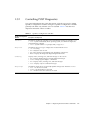
1.3.2
Controlling POST Diagnostics
You control POST diagnostics (and other aspects of the boot process) by setting
OpenBoot configuration variables. Changes to OpenBoot configuration variables
generally take effect only after the server is restarted. TABLE 1-2 lists the most
important and useful of these variables.
TABLE 1-2
OpenBoot Configuration
Variable
OpenBoot Configuration Variables
Description and Keywords
auto-boot
Determines whether the operating system automatically starts boot. Default is true.
• true – System automatically boots operating system, once firmware diagnostics
and initialization complete.
• false – System remains at ok prompt until you type boot.
diag-level
Determines the level or type of diagnostics executed. Default is max.
• off – No testing.
• min – Only basic tests are run.
• max – More extensive tests might be run, depending on the device.
• menu – Displays the Diagnostics Engineering Monitor menu.
verbosity
Displays notice, warning, error, and fatal messages on the console.
• max – Displays detailed progress and informational messages.
• normal – Keeps regular output to a minimum.
• min – Displays notice, warning, error, and fatal messages.
• none – Displays only error and fatal messages.
diag-script
Determines which devices are tested by OpenBoot Diagnostics. Default is normal.
• none – No devices are tested.
• normal – On-board devices are tested.
• all – All devices that have self-tests are tested.
Chapter 1
Diagnosing Server Performance and Faults
1-7
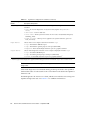
TABLE 1-2
OpenBoot Configuration
Variable
OpenBoot Configuration Variables (Continued)
Description and Keywords
diag-trigger
Determines under what reset conditions, POST/OpenBoot Diagnostics shall be
executed.
• none – Do not run diagnostics on any reset event (requires diag–switch? =
false)
• user-reset – User invoked reset
• error-reset – When system encounters an error reset event (Red State Exception,
Watchdog, Fatal).
• power-on-reset – When power is applied to the system. Default is (power-onreset, error-reset).
input-device
Selects where console input is taken from. Default is ttya.
• ttya – From built-in SER MGT port.
• ttyb – From built-in general purpose serial port (SER TTYB)
• keyboard – From attached keyboard that is part of a graphics terminal.
output-device
Selects where diagnostic and other console output is displayed. Default is ttya.
• ttya – To built-in SER MGT port.
• ttyb – To built-in general purpose serial port (SER TTYB).
• screen – To attached screen that is part of a graphics terminal.1
1 – POST messages cannot be displayed on a graphics terminal. Messages are sent to TTYA when the output-device is set to screen.
Note – These variables affect OpenBoot Diagnostics tests as well as POST
diagnostics.
After POST diagnostics have finished running, POST reports back to the OpenBoot
firmware the status of each test it has run. Control then reverts back to the OpenBoot
firmware code.
If POST diagnostics do not uncover a fault, and the server still does not start up, run
OpenBoot Diagnostics tests. See FIGURE 1-1 for additional information.
1-8
Sun Fire V215 and V245 Servers Service Guide • September 2006
1.4
OpenBoot Diagnostics
Like POST diagnostics, OpenBoot diagnostics code is firmware-based and resides in
the OpenBoot PROM.
1.4.1
Starting OpenBoot Diagnostics
1. Obtain the ok prompt.
Become superuser, and then type init 0.
2. Type:
ok obdiag
This command displays the OpenBoot Diagnostics menu.
Note – If you have a PCI card installed in the server, then additional tests will
appear on the obdiag menu.
3. Run an obdiag test. Type:
obdiag> test n
Where n represents the number corresponding to the test you want to run.
A summary of the tests is available. At the obdiag> prompt, type:
obdiag> help
1.4.2
Controlling OpenBoot Diagnostics Tests
Most of the OpenBoot configuration variables you use to control POST (see
TABLE 1-2) also affect OpenBoot diagnostics tests.
■
Use the diag-level variable to control the OpenBoot diagnostics testing level.
■
Use test-args to customize how the tests run.
Chapter 1
Diagnosing Server Performance and Faults
1-9
By default, test-args is set to contain an empty string. You can modify testargs using one or more of the reserved keywords shown in TABLE 1-3.
TABLE 1-3
Keywords for the test-args OpenBoot Configuration Variable
Keyword
What It Does
bist
Invokes built-in self-test (BIST) on external and peripheral devices
debug
Displays all debug messages
iopath
Verifies bus and interconnect integrity
loopback
Exercises external loopback path for the device
media
Verifies external and peripheral device media accessibility
restore
Attempts to restore original state of the device if the previous
execution of the test failed
silent
Displays only errors rather than the status of each test
subtests
Displays main test and each subtest that is called
verbose
Displays detailed messages of status of all tests
callers=N
Displays backtrace of N callers when an error occurs
• callers=0 - displays backtrace of all callers before the error
errors=N
Continues executing the test until N errors are encountered
• errors=0 - displays all error reports without terminating testing
If you want to customize the OpenBoot diagnostics testing, you can set test-args
to a comma-separated list of keywords, as in this example:
ok setenv test-args debug,loopback,media
1.4.2.1
test and test-all Commands
You can run OpenBoot Diagnostics tests directly from the ok prompt. To do this,
type the test command, followed by the full hardware path of the device (or set of
devices) to be tested. For example:
ok test /ebus@1f,464000/serial@2,40
1-10
Sun Fire V215 and V245 Servers Service Guide • September 2006
Note – Knowing how to construct an appropriate hardware device path requires
precise knowledge of the hardware architecture of the Sun Fire V215 and V245
servers.
To customize an individual test, you can use test-args as follows:
ok test /ebus@1f,464000/serial@2,40:test-args={verbose,debug}
This affects only the current test without changing the value of the test-args
OpenBoot configuration variable.
You can test all the devices in the device tree with the test-all command:
ok test-all
If you specify a path argument to test-all, then only the specified device and its
children are tested. The following example shows the command to test the USB bus
and all devices with self-tests that are connected to the USB bus:
ok test-all /pci@9,700000/usb@1,3
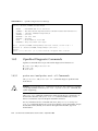
1.4.2.2
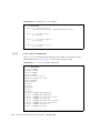
What OpenBoot Diagnostics Error Messages Tell You
OpenBoot diagnostics error messages are reported in a tabular format that contains a
short summary of the problem, the hardware device affected, the subtest that failed,
and other diagnostic information. CODE EXAMPLE 1-1 displays a example OpenBoot
diagnostics error message.
Chapter 1
Diagnosing Server Performance and Faults
1-11
OpenBoot Diagnostics Error Message
CODE EXAMPLE 1-1
Testing /ebus@1f,464000/flashprom@0,0
ERROR
:
SUMMARY :
DEVICE :
SUBTEST :
MACHINE :
SERIAL# :
DATE
:
CONTR0LS:
FLASHPROM CRC-32 is incorrect
Obs=0x1ea5bc20 Exp=0x5c896226 XOR=0x422cde06 Addr=0xfeb1fffc
/ebus@1f,464000/flashprom@0,0
selftest
Sun Fire V215
64196915
04/07/2006 23:27:45 GMT
diag-level=max test-args=
Error: /ebus@1f,464000/flashprom@0,0 selftest failed, return code = 1
Selftest at /ebus@1f,464000/flashprom@0,0 (errors=1) .............
failed
Pass:1 (of 1) Errors:1 (of 1) Tests Failed:1 Elapsed Time: 0:0:0:1
1.4.3
OpenBoot Diagnostic Commands
OpenBoot commands that can provide useful diagnostic information are:
■
■
■
1.4.3.1
probe-scsi and probe-scsi-all
probe-ide
show-devs
probe-scsi and probe-scsi-all Commands
The probe-scsi and probe-scsi-all commands diagnose problems with
SCSI devices.
Caution – If you use the halt command or the Stop-A key sequence to reach the
ok prompt and then issue the probe-scsi or probe-scsi-all command, the
syetem might hang.
The probe-scsi command communicates with all SCSI devices connected to onboard SCSI controllers. The probe-scsi-all command additionally accesses
devices connected to any host adapters installed in PCI slots.
For any SCSI device that is connected and active, the probe-scsi and probescsi-all commands display its loop ID, host adapter, logical unit number, unique
World Wide Name (WWN), and a device description that includes type and
manufacturer.
1-12
Sun Fire V215 and V245 Servers Service Guide • September 2006
The following is example output from the probe-scsi command.
CODE EXAMPLE 1-2
Example probe-scsi Output
{1} ok probe-scsi
MPT Version 1.05, Firmware version 0.03.23.00
Target 0
Unit 0
Blocks, 73
Target 1
Unit 0
bLOCKS, 73
Disk
FUJITSU MAY2073RCSUN72G 0401 143374738
GB SASAddress 500000e011772152 PhyNum 0
Disk
FUJITSU MAY2073RCSUN72 0401
143374738
gb SASAdress 500000@e0115adf42 PhyNum 1
The following is example output from the probe-scsi-all command.
CODE EXAMPLE 1-3
Example probe-scsi-all Output.
{1} ok probe-scsi-all
/pci@1e,600000/pci@0/pci@a/pci@0/pci@8/scsi@1
MPT Version 1.05 Firmware Version 0.03.23.00
Target 0
Unit 0
Disk FUJITSU MAY2073RCSUN72G 0401 143374738 Blocks,
73GB SASAddress 500000e011772152 PhyNum 0
Target 1
Unit 0
Disk FUJITSUMAY2073RCSUN72G 0401 143374738 Blocks,
73GB SASAddress 500000e0115adf42 PhyNum 1
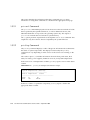
1.4.3.2
probe-ide Command
The probe-ide command communicates with all Integrated Drive Electronics (IDE)
devices connected to the IDE bus. This is the internal system bus for media devices
such as the optional DVD super-multi drive.
Caution – If you used the halt command or the Stop-A key sequence to reach the
ok prompt, then issuing the probe-ide command can hang the system.
The following is example output from the probe-ide command.
Chapter 1
Diagnosing Server Performance and Faults
1-13
CODE EXAMPLE 1-4
Example probe-ide Output
{1} ok probe-ide
Device 0 ( Primary Master )
Removable ATAPI Model: MATSHITADVD-RAM UJ-845S
Device 1 ( Primary Slave )
Not Present
Device 2 ( Secondary Master )
Not Present
Device 3 ( Secondary Slave )
Not Present
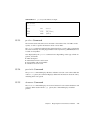
1.4.3.3
show-devs Command
The show-devs command lists the hardware device paths for each device in the
firmware device tree. CODE EXAMPLE 1-5 shows some example output.
CODE EXAMPLE 1-5
show-devs Output (Truncated)
{1} ok show-devs/
/i2c@1f,530000
/ebus@1f,464000
/pci@1f,700000
/pci@1e,600000
/memory-controller@0,0
/SUNW,UltraSPARC-IIIi+0,0
/virtual-memory
/memory@m0,0
/aliases
/options
/openprom
/chosen
/packages
/i2c@1f, 5300000/dimm-spd@0,e2
/i2c@1f, 5300000/dimm-spd@0,e0
/i2c@1f, 5300000/clock-generator@0,dc
/i2c@1f, 5300000/rscrtc@0,d0
/i2c@1f, 5300000/hardware-monitor@0,b0
/i2c@1f, 5300000/riser-fru-prom@0,a8
/i2c@1f, 5300000/idprom@0,a6
/i2c@1f, 5300000/nvram,a6
1-14
Sun Fire V215 and V245 Servers Service Guide • September 2006
1.4.3.4
Running OpenBoot Commands
1. Halt the system to reach the ok prompt.
How you do this depends on the system’s condition. If possible, warn users before
you shut the system down. One method is to become superuser and then type
init 0
2. Type the appropriate OpenBoot command at the console prompt.
1.5
Operating System Diagnostic Tools
If a system passes OpenBoot Diagnostics tests, it normally attempts to boot its
multiuser operating system. For most Sun systems, this means the Solaris OS. After
the server is running in multiuser mode, you have access to the software-based
diagnostic tools, SunVTS and Hardware Diagnostic Suite. These tools enable you to
monitor the server, exercise it, and isolate faults.
Note – If you set the auto-boot OpenBoot configuration variable to false, the
operating system does not boot following completion of the firmware-based tests.
In addition to the tools mentioned above, you can refer to error and system message
log files, and Solaris system information commands.
1.5.1
Error and System Message Log Files
Error and other system messages are saved in the /var/adm/messages file.
Messages are logged to this file from many sources, including the operating system,
the environmental control subsystem, and various software applications.
1.5.2
Solaris System Information Commands
The following Solaris commands display data that you can use when assessing the
condition of a Sun Fire V215 or V245 server:
■
■
■
■
■
prtconf
prtdiag
prtfru
psrinfo
showrev
Chapter 1
Diagnosing Server Performance and Faults
1-15
This section describes the information that these commands give you. More
information on using these commands is contained in the appropriate man page.
1.5.2.1
prtconf Command
The prtconf command displays the Solaris device tree. This tree includes all of the
devices probed by the OpenBoot firmware, as well as additional devices, like
individual disks that are exposed to the operating system only. The output of
prtconf also includes the total amount of system memory.
The -p option produces output similar to the OpenBoot show-devs command. This
output lists only those devices that are compiled by the system firmware.
1.5.2.2
prtdiag Command
The prtdiag command displays a table of diagnostic information that summarizes
the status of system components. The display format used by the prtdiag
command can vary depending on what version of the Solaris OS is running on the
system.
The verbose option (-v) includes information about the front panel status, disk
status, fan status, power supplies, hardware revisions, and system temperatures.
In the event of an overtemperature condition, prtdiag reports an error in the Status
column.
CODE EXAMPLE 1-6
prtdiag Overtemperature Indicator Output
System Temperatures (Celsius):
------------------------------Device Temperature
Status
--------------------------------------CPU0
62
OK
CPU1
102
ERROR
If there is a failure of a particular component, prtdiag reports a fault in the
appropriate Status column.
1-16
Sun Fire V215 and V245 Servers Service Guide • September 2006
CODE EXAMPLE 1-7
prtdiag Fault Indicator Output
Fan Status:
----------Bank
---CPU0
CPU1
1.5.2.3
RPM
----4166
0000
Status
-----[NO_FAULT]
[FAULT]
prtfru Command
The Sun Fire V215 and V245 servers maintain a hierarchical list of all FRUs in the
system, as well as specific information about various FRUs.
The prtfru command can display this hierarchical list, as well as data contained in
the serial electrically-erasable programmable read-only memory (SEEPROM) devices
located on many FRUs.
Data displayed by the prtfru command varies depending on the type of FRU. In
general, it includes:
■
■
■
■
1.5.2.4
FRU description
Manufacturer name and location
Part number and serial number
Hardware revision levels
psrinfo Command
The psrinfo command displays the date and time each CPU came online. With the
verbose (-v) option, the command displays additional information about the CPUs,
including their clock speed.
1.5.2.5
showrev Command
The showrev command displays revision information for the current hardware and
software. When used with the (-p) option, this command displays installed
patches.
Chapter 1
Diagnosing Server Performance and Faults
1-17
1.6
Recent Diagnostic Test Results
Summaries of the results from the most recent POST and OpenBoot diagnostics tests
are saved across power cycles.
1.6.1
Viewing Recent Test Results
1. Obtain the ok prompt.
2. Do either of the following:
■
To see a summary of the most recent POST results, type:
ok show-post-results
■
To see a summary of the most recent OpenBoot diagnostics test results, type:
ok show-obdiag-results
This produces a system-dependent list of hardware components, along with an
indication of which components passed and which failed POST or OpenBoot
diagnostics tests.
1.7
Additional Diagnostic Tests for Specific
Devices
You can use the probe-scsi, probe-scsi-all, probe-ide, watch-net, and
watch-net-all commands to perform additional diagnostic tests on specific
devices. This section contains procedures for using these commands.
1-18
Sun Fire V215 and V245 Servers Service Guide • September 2006
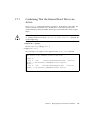
1.7.1
Confirming That the Internal Hard Drives are
Active
The probe-scsi command transmits an inquiry to SCSI devices connected to the
system’s internal SCSI interface. If a SCSI device is connected and active, the
command displays the unit number, device type, and manufacturer name for that
device.
Caution – If you use the halt command or the Stop-A key sequence to reach the
ok prompt and then issue the probe-scsi or probe-scsi-all command, the
system might hang.
1. Obtain the ok prompt.
Become superuser and type init 0
2. Type probe-scsi.
The following is an example of the output from the probe-scsi command.
MPT Version 1.05, Firmware version 0.03.23.00
Target 0
Unit 0
Blocks, 73
Target 1
Unit 0
bLOCKS, 73
Disk
FUJITSU MAY2073RCSUN72G 0401 143374738
GB SASAddress 500000e011772152 PhyNum 0
Disk
FUJITSU MAY2073RCSUN72 0401
143374738
gb SASAdress 500000@e0115adf42 Phynum 1
Chapter 1
Diagnosing Server Performance and Faults
1-19
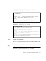
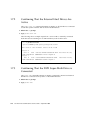
1.7.2
Confirming That the External Hard Drives Are
Active
The probe-scsi-all command transmits an inquiry to all SCSI devices connected
to both the system’s internal and its external SCSI interfaces.
1. Obtain the ok prompt.
2. Type probe-scsi-all
The following shows example output from a server with no externally connected
SCSI devices but containing two 73 GB hard drives, both of them active.
{1} ok probe-scsi-all
/pci@1e,600000/pci@0/pci@a/pci@0/pci@8/scsi@1
MPT Version 1.05 Firmware Version 0.03.23.00
Target 0
Unit 0
Disk FUJITSU MAY2073RCSUN72G 0401 143374738 Blocks,
73GB SASAddress 500000e011772152 PhyNum 0
Target 1
Unit 0
Disk FUJITSUMAY2073RCSUN72G 0401 143374738 Blocks,
73GB SASAddress 500000e0115adf42 PhyNum 1
1.7.3
Confirming That the DVD Super-Multi Drive is
Connected
The probe-ide command transmits an inquiry command to internal and external
IDE devices connected to the system’s on-board IDE interface.
1. Obtain the OK prompt.
2. Type probe-ide.
1-20
Sun Fire V215 and V245 Servers Service Guide • September 2006
The following example output shows a optional DVD super-multi drive installed (as
Device 0) and active in a server.
{1} ok probe-ide
Device 0 ( Primary Master )
Removable ATAPI Model: MATSHITADVD-RAM UJ-845S
Device 1 ( Primary Slave )
Not Present
Device 2 ( Secondary Master )
Not Present
Device 3 ( Secondary Slave )
Not Present
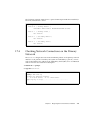
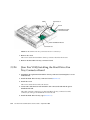
1.7.4
Checking Network Connections on the Primary
Network
The watch-net diagnostics test monitors Ethernet packets on the primary network
interface. Good packets received by the system are indicated by a period (.). Errors
such as the framing error and the cyclic redundancy check (CRC) error are indicated
with an X and an associated error description.
1. Obtain the ok prompt.
2. Type the watch-net.
{1}ok watch-net
100Mbps FDX Link up
Looking for Ethernet Packets.
‘.’ is a Good Packet. ‘X’ is a Bad Packet
Type any key to stop................................
Chapter 1
Diagnosing Server Performance and Faults
1-21
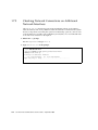
1.7.5
Checking Network Connections on Additional
Network Interfaces
The watch-net-all diagnostics test monitors Ethernet packets on the primary
network interface and on any additional network interfaces connected to the system
board. Good packets received by the system are indicated by a period (.). Errors such
as the framing error and the cyclic redundancy check (CRC) error are indicated with
an X and an associated error description.
1. Obtain the ok prompt.
Become superuser and type init 0
2. Type watch-net-all at the prompt.
{1}ok watch-net-all
/pci@1e,600000/pci@0/pci@a/pci@0/[email protected]
100Mbps FDX Link up
Looking for Ethernet Packets
‘.’ is a Good Packet. ‘X’ is a Bad Packet
Type any key to stop................................
1-22
Sun Fire V215 and V245 Servers Service Guide • September 2006
CHAPTER
2
Replacing Hot-Pluggable and HotSwappable CRUs
This chapter describes how to replace the hot-swappable and hot-pluggable
customer replaceable units (CRUs) in the Sun Fire V215 and V245 servers.
The following topics are covered:
■
■
■
■
■
Section 2.1,
Section 2.2,
Section 2.3,
Section 2.4,
Section 2.5,
“Devices That are Hot-Pluggable or Hot-Swappable” on page 2-2
“Hot-Plugging a Hard Drive” on page 2-2
“Hot-Swapping a Fan Tray” on page 2-7
“Hot-Swapping a Hard Drive Fan Tray” on page 2-11
“Hot-Swapping a Power Supply” on page 2-13
2-1
2.1
Devices That are Hot-Pluggable or HotSwappable
Hot-pluggable devices are those devices that you can remove and install while the
server is running, but you must perform administrative tasks before or after
installing the hardware (for example, mounting a hard drive). In the Sun Fire V215
and V245 servers, the following device is hot-pluggable:
■
Hard drives
Hot-swappable devices are those devices that can be removed and installed while
the server is running without affecting the rest of the servers capabilities. In the Sun
Fire V215 and V245 servers the following devices are hot-swappable:
■
■
■
Fan trays
Hard drive fan tray
Power supplies
Note – In Sun Fire V215 and V245 servers, the chassis-mounted hard drives can be
hot-swappable (depending on how they are configured).
2.2
Hot-Plugging a Hard Drive
The hard drives in the Sun Fire V215 and V245 servers are hot-pluggable, but this
capability depends on how the hard drives are configured. To hot-plug a drive you
must take the drive offline (to prevent any applications from accessing it, and to
remove the logical software links to it) before you can safely remove it.
The following situations inhibit your ability to hot-plug a drive:
■
If the hard drive contains the operating system, and the operating system is not
mirrored on another drive.
■
If the hard drive cannot be logically isolated from the online operations of the
server.
If your drive falls into one of these conditions, you must shut the server down before
you replace the hard drive. See Section 3.2.2, “Powering Off the Server – ALOM
Command Line” on page 3-4 or Section 3.2.3, “Powering Off the Server – Graceful
Shutdown” on page 3-5 or Section 3.2.4, “Powering Off the Server – Emergency
Shutdown” on page 3-5.
2-2
Sun Fire V215 and V245 Servers Service Guide • September 2006
2.2.1
Removing a Hard Drive
Removing a hard drive from the Sun Fire V215 and V245 servers is a three step
process. You must first identify the drive you wish to remove, unconfigure that drive
from the server, and then manually remove the drive from the chassis.
Perform the following process to remove a hard drive:
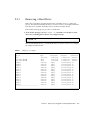
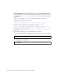
1. At the Solaris prompt, issue the cfgadm -al command to list all drives in the
device tree, including drives that are not configured. Type:
# cfgadm -al
This should identify the Ap_id for the hard drive you wish to remove. For example,
the output should look like:
TABLE 2-1
Sample Ap_id Output
Ap_id
c0
c0::dsk/c0t0d0
c0::dsk/c0t1d0
usb0/1
usb0/2
usb0/3
usb1/1
usb1/2
usb1/3
usb2/1
usb2/2
usb2/3
usb2/4
usb2/5
usb2/6
usb2/7
usb2/8
----------------------------
Type
scsi-bus
disk
disk
unknown
unknown
unknown
unknown
unknown
unknown
unknown
unknown
unknown
unknown
unknown
unknown
unknown
unknown
Chapter 2
Receptacle
connected
connected
connected
empty
empty
empty
empty
empty
empty
empty
empty
empty
empty
empty
empty
empty
empty
Occupant
Condition
configured
unknown
configured
unknown
configured
unknown
unconfigured ok
unconfigured ok
unconfigured ok
unconfigured ok
unconfigured ok
unconfigured ok
unconfigured ok
unconfigured ok
unconfigured ok
unconfigured ok
unconfigured ok
unconfigured ok
unconfigured ok
unconfigured ok
Replacing Hot-Pluggable and Hot-Swappable CRUs
2-3
2. Issue the cfgadm -c unconfigure command to unconfigure the disk. For
example, type:
# cfgadm -c unconfigure c0::dsk/c0t1d1
Where c0:dsk/c0t1d1 is the disk that you are trying to unconfigure.
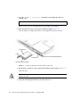
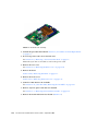
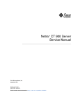
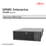
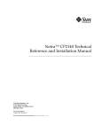
3. Wait until the blue service action allowed indicator lights (FIGURE 2-1).
This will help you identify which drive is unconfigured and can be removed.
Hard drive 0
Latch
Hard drive 1
Service action allowed indicator
Hard drive release button
FIGURE 2-1
Locating the Hard Drive Release Button and Latch
4. On the drive you plan to remove, push the hard drive release button (FIGURE 2-1).
The latch opens.
Caution – The latch is not an ejector. Do not bend it too far to the left. Doing so can
damage the latch.
5. Grasp the latch and pull the drive out of the drive slot.
2-4
Sun Fire V215 and V245 Servers Service Guide • September 2006
2.2.2
Installing a Hard Drive
Installing a hard drive into the Sun Fire V215 and V245 servers is a two step process.
You must first install a hard drive into the drive slot that you wish to install the
drive in, and then you must configure that drive to the server.
Perform the following process to install a hard drive.
1. If necessary, remove the blank panel from the chassis.
Note – Sun Fire V215 servers might have a single blank panel that covers the hard
drive slot. Sun Fire V245 servers might have as many as three blank panels which
cover the unoccupied hard drive slots.
2. Align the replacement drive to the drive slot (FIGURE 2-1).
Hard drives are physically addressed according to the slot in which they are
installed. If you removed an existing hard drive from a slot in the server, you must
install the replacement drive in the same slot as the drive that was removed.
3. Slide the drive into the drive slot until it is fully seated.
4. Close the latch to lock the drive in place.
5. At the Solaris prompt, issue the cfgadm -al command to list all drives in the
device tree, including any drives that are not configured. Type:
# cfgadm -al
This should help you identify the Ap_id for the hard drive you installed. For
example, the output should look like:
Chapter 2
Replacing Hot-Pluggable and Hot-Swappable CRUs
2-5
TABLE 2-2
Sample Ap_id Output
Ap_id
Type
c0
scsi-bus
c0::dsk/c0t0d0
disk
c0::sd1
disk
usb0/1
unknown
usb0/2
unknown
usb0/3
unknown
usb1/1
unknown
usb1/2
unknown
usb1/3
unknown
usb2/1
unknown
usb2/2
unknown
usb2/3
unknown
usb2/4
unknown
usb2/5
unknown
usb2/6
unknown
usb2/7
unknown
usb2/8
unknown
---------------------------------
Receptacle
connected
connected
connected
empty
empty
empty
empty
empty
empty
empty
empty
empty
empty
empty
empty
empty
empty
Occupant
Condition
configured
unknown
configured
unknown
unconfigured unknown
unconfigured ok
unconfigured ok
unconfigured ok
unconfigured ok
unconfigured ok
unconfigured ok
unconfigured ok
unconfigured ok
unconfigured ok
unconfigured ok
unconfigured ok
unconfigured ok
unconfigured ok
unconfigured ok
6. Issue the cfgadm -c configure command to configure the disk. For example,
type:
# cfgadm -c configure c0::sd1
Where c0::sd1 is the disk that you are trying to configure.
7. Wait until the blue service action allowed indicator goes off on the drive that you
installed (FIGURE 2-1).
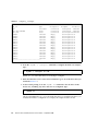
8. At the Solaris prompt, issue the cfgadm -al command to list all drives in the
device tree, including any drives that are not configured. Type:
# cfgadm -al
This should identify the Ap_id for the hard drive that you installed. The drive you
installed should be is configured. For example, the output should look like:
2-6
Sun Fire V215 and V245 Servers Service Guide • September 2006
TABLE 2-3
Sample Ap_id Output
Ap_Id
Type
c0
scsi-bus
c0::dsk/c0t0d0
disk
c0::dsk/c0t1d0
disk
usb0/1
unknown
usb0/2
unknown
usb0/3
unknown
usb1/1
unknown
usb1/2
unknown
usb1/3
unknown
usb2/1
unknown
usb2/2
unknown
usb2/3
unknown
usb2/4
unknown
usb2/5
unknown
usb2/6
unknown
usb2/7
unknown
usb2/8
unknown
----------------------------------
Receptacle
connected
connected
connected
empty
empty
empty
empty
empty
empty
empty
empty
empty
empty
empty
empty
empty
empty
Occupant
Condition
configured
unknown
configured
unknown
configured
unknown
unconfigured ok
unconfigured ok
unconfigured ok
unconfigured ok
unconfigured ok
unconfigured ok
unconfigured ok
unconfigured ok
unconfigured ok
unconfigured ok
unconfigured ok
unconfigured ok
unconfigured ok
unconfigured ok
9. Issue the iostat -E command. Type:
# iostat -E
The iostat -E command displays information about your systems installed
devices such as manufacturer, model number, serial number, size and system error
statistics.
2.3
Hot-Swapping a Fan Tray
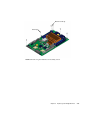
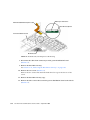
Six hot-swappable fans trays are located under the front cover door.
Two working fan trays are required to provide adequate cooling for the Sun Fire
V215 and V245 servers. If a fan tray fails, replace it as soon as possible to maximize
server availability.
Chapter 2
Replacing Hot-Pluggable and Hot-Swappable CRUs
2-7
The following indicators are lit when a fan tray fault is detected:
■
■
■
Front and rear Service Required indicators (FIGURE 2-3) and (FIGURE 2-4).
Top Fan indicator on the front of the server (FIGURE 2-3)
Fan Fault indicator on the faulty fan (FIGURE 2-2)
If an overtemperature conditions occurs, the front panel CPU overtemperature
indicator lights and a message is displayed on the console and logged by ALOM.
Tip – You can use the showfault command at the sc> prompt to view the current
faults.
2.3.1
Removing a Fan Tray
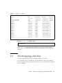
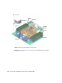
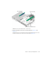
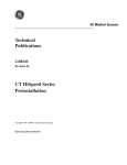
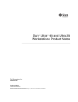
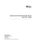
1. Gain access to the top of the server where the front cover door for the fan tray is
located (FIGURE 2-2).
2-8
Sun Fire V215 and V245 Servers Service Guide • September 2006
.
You might need to extend the server to a maintenance position. See Section 3.2.5,
“Extending the Server to the Maintenance Position – Rackmounted Servers Only” on
page 3-5.
Latch
Front cover door
Fan tray (6)
Fan Fault indicator (6)
Handle
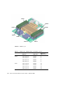
FIGURE 2-2
Removing a Fan Tray
2. Lift the latch, and open the front cover door.
3. Identify the faulty fan tray.
A lit Fan Fault indicator on the top of a fan tray indicates that the fan tray is faulty.
Chapter 2
Replacing Hot-Pluggable and Hot-Swappable CRUs
2-9
Note – Sun Fire V215 servers have 2 fans installed in each fan tray.
4. Pull up on the fan tray handle until the fan tray is removed from the chassis.
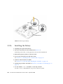
2.3.2
Installing a Fan Tray
1. With the front cover door open, install the replacement fan tray into the server
(FIGURE 2-2).
2. Apply firm pressure to fully seat the fan tray.
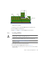
3. Verify that the Fan Fault indicator on the replaced fan tray is not lit. Also verify
that the Top Fan indicator, Service Required indicators, and the Locator
indicator/Locator button are not lit (FIGURE 2-2), (FIGURE 2-3) and (FIGURE 2-4).
Locator indicator/Locator button
Top Fan indicator
Service Required indicator
FIGURE 2-3
Top Fan, System Required Indicator, Locator Indicators, and Locator Button
Service Required indicator
Failure indicator
FIGURE 2-4
Failure and Service Required Indicators
Note – Each power supply has a failure indicator.
2-10
Sun Fire V215 and V245 Servers Service Guide • September 2006
4. Close the front cover door.
5. If necessary, return the server to its normal position in the rack.
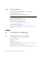
2.4
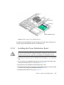
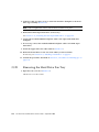
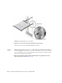
Hot-Swapping a Hard Drive Fan Tray
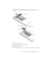
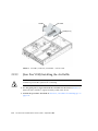
A single hot-swappable fan tray is located under the rear fan tray cover door (Sun
Fire V245 server).
Note – This hot-swappable fan tray is located under front fan tray cover door on the
Sun Fire V215 server.
If the fan tray fails, replace it as soon as possible to maximize server availability.
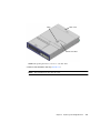
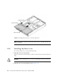
2.4.1
Removing a Hard Drive Fan Tray
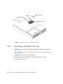
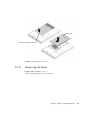
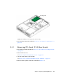
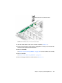
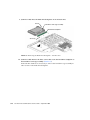
1. Gain access to the top of the server where the rear cover door for the fan tray is
located (FIGURE 2-5).
The hot-swappable fan tray for the Sun Fire V215 server is located under the front
fan tray cover door.
Note – You might need to extend the server to a maintenance position. See
Section 3.2.5, “Extending the Server to the Maintenance Position – Rackmounted
Servers Only” on page 3-5.
2. Lift the latch, and open the rear cover door.
3. Verify that the fan tray is faulty.
A lit Fan Fault indicator on the top of a fan tray indicates that the fan tray is faulty.
Note – The hard drive fan tray has two fans.
4. Pull up on the fan tray handle and remove the fan tray from the chassis.
Chapter 2
Replacing Hot-Pluggable and Hot-Swappable CRUs
2-11
Handle
Rear cover door
Fan Fault indicator
Rear cover
FIGURE 2-5
2.4.2
Hard drive fan tray
Hard Drive Fan Tray – Sun Fire V245 Server
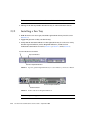
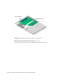
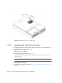
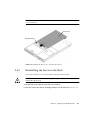
Installing a Hard Drive Fan Tray
1. With the rear cover door open, install the replacement fan tray into the server
(FIGURE 2-5).
The hot-swappable fan tray for the Sun Fire V215 server is located under front fan
tray cover door.
2. Apply firm pressure to fully seat the fan tray.
3. Verify that the Fan Fault indicator on the replaced fan tray is not lit.
4. Close the rear cover door.
2-12
Sun Fire V215 and V245 Servers Service Guide • September 2006
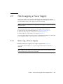
2.5
Hot-Swapping a Power Supply
The Sun Fire V245 server’s standard redundant hot-swappable power supplies
enable you to remove and replace a power supply without shutting the server down
provided that the other power supply is online and working.
Note – An optional redundant, hot-swappable power supply is available for the Sun
Fire V215 server.
The following indicators are lit when a power supply fault is detected:
■
■
■
Front and rear Service Required indicators (FIGURE 2-3) or (FIGURE 2-4).
Rear PS Failure indicator on the bezel of the server (FIGURE 2-4)
Failure indicator on the faulty power supply (FIGURE 2-6)
If a power supply fails and you do not have a replacement available, leave the failed
power supply installed to ensure proper air flow in the server.
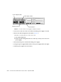
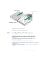
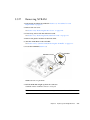
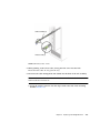
2.5.1
Removing a Power Supply
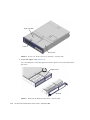
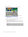
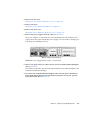
1. Identify which power supply (0 or 1) requires replacement (FIGURE 2-6).
A lit (amber) failure indicator on a power supply indicates that a failure was
detected.
Tip – Additional information about power supply status can be found the Sun Fire
V215 and V245 Getting Started Guide (819-3041).
Chapter 2
Replacing Hot-Pluggable and Hot-Swappable CRUs
2-13
Power supply 0 (PS0)
Power supply 1 (PS1)
Release Latch (2)
FIGURE 2-6
Failure indicator
Location of the Power Supplies and Release Latches
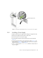
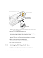
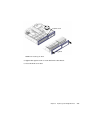
2. Gain access to the rear of the server where the faulty power supply is located.
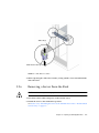
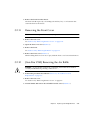
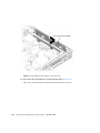
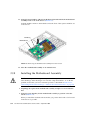
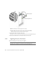
3. Release the cable management arm (CMA) (FIGURE 2-7).
The CMA is located at the rear of the server rack.
a. Press and hold the tab.
b. Rotate the cable management arm out of the way so that you can access the
power supply.
4. Disconnect the power cord from the faulty power supply.
5. Grasp the power supply handle and move the power supply latch to the right.
6. Pull the power supply out of the chassis.
2-14
Sun Fire V215 and V245 Servers Service Guide • September 2006
Cable management arm
3a
3b
FIGURE 2-7
2.5.2
Rotating the Cable Management Arm to Access the Server Power Supplies
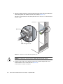
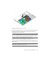
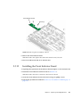
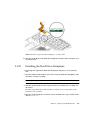
Installing a Power Supply
1. Align the replacement power supply with the empty power supply chassis bay.
2. Slide the power supply into the bay until it is fully seated.
3. Reconnect the power cord to the power supply.
4. Close the CMA, inserting the end of the CMA into the rear left rail bracket
(FIGURE 2-7).
5. Verify that the Failure indicator on the replaced power supply (FIGURE 2-4), the
Service Required (FIGURE 2-3) indicator, and the front and rear Service Required
indicators are not lit (FIGURE 2-3) and (FIGURE 2-4).
6. At the sc> prompt, type the showenvironment command to verify the status of
the power supplies.
Chapter 2
Replacing Hot-Pluggable and Hot-Swappable CRUs
2-15
2-16
Sun Fire V215 and V245 Servers Service Guide • September 2006
CHAPTER
3
Replacing Cold-Swappable FRUs
This chapter describes how to replace cold-swappable, field-replaceable units (FRUs)
in the Sun Fire V215 and V245 servers.
The following topics are covered:
■
■
■
■
Section 3.1,
Section 3.2,
Section 3.3,
Section 3.4,
“Safety Information” on page 3-2
“Procedures for Parts Replacement” on page 3-3
“Removing and Installing FRUs” on page 3-15
“Procedures for Finishing Up” on page 3-58
For a list of CRUs and FRUs, see Section B.1, “Customer and Field Replaceable
Units” on page B-1.
Caution – Never attempt to run the server with the covers removed. Hazardous
voltage present.
Caution – Equipment damage possible. The covers must be in place for proper air
flow.
3-1
3.1
Safety Information
This section describes important safety information that you need to know prior to
removing or installing parts in the Sun Fire V215 and V245 servers.
For your protection, observe the following safety precautions when setting up your
equipment:
3.1.1
■
Follow all Sun cautions, warnings, and instructions marked on the equipment
and described in Important Safety Information for Sun Hardware Systems (816-7190).
■
Follow all cautions, warnings, and instructions marked on the equipment and
described in the Sun Fire V215 and V245 Compliance and Safety Manual (819-3039).
■
Ensure that the voltage and frequency of your power source match the voltage
and frequency inscribed on the equipment’s electrical rating label.
■
Follow the electrostatic discharge safety practices as described in this section.
Safety Symbols
The following symbols might appear in this document, note their meanings:
Caution – There is a risk of personal injury and or equipment damage. To avoid
personal injury and equipment damage, follow the instructions.
Caution – Hot surface. Avoid contact. Surfaces are hot and might cause personal
injury if touched.
Caution – Hazardous voltages are present. To reduce the risk of electric shock and
danger to personal health, follow the instructions.
3-2
Sun Fire V215 and V245 Servers Service Guide • September 2006
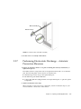
3.1.2
Electrostatic Discharge Safety Measures
Electrostatic discharge (ESD) sensitive devices, such as the motherboards, PCI cards,
hard drives, and memory cards require special handling.
Caution – Circuit boards and hard drives contain electronic components that are
extremely sensitive to static electricity. Ordinary amounts of static electricity from
clothing or the work environment can destroy the components located on these
boards. Do not touch the components along their connector edges.
3.1.2.1
Using an Antistatic Wrist Strap
Wear an antistatic wrist strap and use an antistatic mat when handling components
such as hard drive assemblies, circuit boards, or PCI cards. When servicing or
removing server components, attach an antistatic strap to your wrist and then to a
metal area on the chassis. Following this practice equalizes the electrical potentials
between you and the server.
Note – An antistatic wrist strap is no longer included in the accessory kit for the
Sun Fire V215 and V245 Servers. However, antistatic wrist straps are still included
with x-options.
3.1.2.2
Using an Antistatic Mat
Place ESD-sensitive components such as motherboards, memory, and other PCBs on
an antistatic mat.
3.2
Procedures for Parts Replacement
Before replacing parts that are not hot-swappable or hot-pluggable inside the Sun
Fire V215 and V245 servers, perform the following procedures:
■
Section 3.2.2, “Powering Off the Server – ALOM Command Line” on page 3-4 or
Section 3.2.3, “Powering Off the Server – Graceful Shutdown” on page 3-5 or
Section 3.2.4, “Powering Off the Server – Emergency Shutdown” on page 3-5
■
Section 3.2.5, “Extending the Server to the Maintenance Position – Rackmounted
Servers Only” on page 3-5
Chapter 3
Replacing Cold-Swappable FRUs
3-3
■
Section 3.2.7, “Performing Electrostatic Discharge – Antistatic Prevention
Measures” on page 3-9
■
Section 3.2.8, “Removing Power From the Server” on page 3-10
Note – These procedures do not apply to the hot-swappable and hot-pluggable
devices (fans, power supplies, and hard drives) described in Chapter 2.
The procedures that you perform after removing, installing, or repairing the servers
are described in Section 3.4, “Procedures for Finishing Up” on page 3-58.
3.2.1
Required Tools
The Sun Fire V215 and V245 servers can be serviced with the following tools:
■
■
■
■
■
3.2.2
Antistatic wrist strap
Antistatic mat
No. 2 Phillips screwdriver
No. 1 Flat-blade screwdriver (battery removal)
Pen or pencil (power on server)
Powering Off the Server – ALOM Command Line
Note – Additional information about powering on the server is located in the Sun
Fire V215 and V245 Servers Administration Guide (819-3036).
You can use ALOM to perform a graceful shutdown of the server and ensure that all
of your data is saved and the server is ready for restart.
1. Login as superuser or equivalent.
Depending on the type of problem, you might want to view server status, log files,
or run diagnostics before you shut down the server. Refer to the Sun Fire V215 and
V245 Server Administration Guide (819-3036) for log file information.
2. Notify affected users.
Refer to your Solaris system administration documentation for additional
information.
3. Save any open files and quit all running programs.
Refer to your application documentation for specific information on these processes.
3-4
Sun Fire V215 and V245 Servers Service Guide • September 2006
4. Shut down the Solaris OS.
Refer to the Solaris system administration documentation for additional information.
5. Switch from the system console to the ALOM sc> prompt by typing the #.
(Pound Period) key sequence.
c. At the ALOM sc> prompt, issue the poweroff -fy command.
sc> poweroff -fy
SC Alert: SC Request to Power Off Host Immediately.
Note – You can also use the Power button on the front of the server to initiate a
graceful server shutdown (See Section 3.2.3, “Powering Off the Server – Graceful
Shutdown” on page 3-5). This button is recessed to prevent accidental server poweroff. Use the tip of a pen to operate this button.
Refer to the Sun Advanced Lights Out Management (ALOM) Administration Guide for
more information about the ALOM poweroff command.
3.2.3
Powering Off the Server – Graceful Shutdown
● Press and release the Power button.
If necessary, use a pen or pencil to press the Power button.
3.2.4
Powering Off the Server – Emergency Shutdown
Caution – All applications and files will be closed abruptly without saving changes.
File system corruption might occur.
● Press and hold the Power button for 4 seconds.
3.2.5
Extending the Server to the Maintenance Position
– Rackmounted Servers Only
If the server is installed in a rack with extendable slide rails use this procedure to
extend the server to the maintenance position.
Chapter 3
Replacing Cold-Swappable FRUs
3-5
1. (Optional) Issue the following command from the ALOM sc> prompt to locate
the system that requires maintenance (FIGURE 3-1).
sc> setlocator on
Locator indicator is on.
Once you have located the server, press the Locator indicator/Locator button to turn
it off.
Locator indicator/Locator button
FIGURE 3-1
Locator Indicator/Locator Button
2. Verify that no cables will be damaged or interfere when the server is extended.
Although the cable management arm (CMA) that is supplied with the server is
hinged to accommodate extending the server, you should ensure that all cables and
cords are capable of extending.
3. From the front of the server, release the two slide release latches (FIGURE 3-2).
Squeeze the green slide release latches to release the slide rails.
3-6
Sun Fire V215 and V245 Servers Service Guide • September 2006
Slide rail (2)
Slide release latch (2)
FIGURE 3-2
Slide Release Latches
4. While squeezing the slide release latches, slowly pull the server forward until the
slide rails latch.
3.2.6
Removing a Server From the Rack
Caution – If necessary, use two people to dismount and carry the chassis.
1. Disconnect all the cables and power cords from the server.
2. Extend the server to the maintenance position.
See Section 3.2.5, “Extending the Server to the Maintenance Position – Rackmounted
Servers Only” on page 3-5.
Chapter 3
Replacing Cold-Swappable FRUs
3-7
3. Press the metal lever that is located on the inner side of the rail to disconnect the
cable management arm (CMA) from the rail assembly (FIGURE 3-3).
The CMA is still attached to the cabinet, but the server chassis is now disconnected
from the CMA.
Metal lever
Cable management arm
FIGURE 3-3
Metal Lever and Cable Management Arm
Caution – If necessary, use two people to dismount and carry the chassis.
4. From the front of the server, pull the release tabs forward and pull the server
forward until it is free of the rack rails (FIGURE 3-4).
A release tab is located on each rail.
3-8
Sun Fire V215 and V245 Servers Service Guide • September 2006
Slide assembly (2)
Release tab (2)
FIGURE 3-4
Release Tabs and Slide Assembly
5. Set the server on a sturdy work surface.
3.2.7
Performing Electrostatic Discharge – Antistatic
Prevention Measures
1. Prepare an antistatic surface to set parts on during the removal, installation, or
replacement process.
Place ESD-sensitive components such as the printed circuit boards on an antistatic
mat. The following items can be used as an antistatic mat:
■
Antistatic bag used to wrap a Sun replacement part
■
Sun ESD mat, part number 250-1088
■
A disposable ESD mat (shipped with some replacement parts or optional system
components)
2. Attach an antistatic wrist strap.
When servicing or removing server components, attach an antistatic strap to your
wrist and then to a metal area on the chassis.
Chapter 3
Replacing Cold-Swappable FRUs
3-9
3.2.8
Removing Power From the Server
Caution – The system supplies standby power to the circuit boards even when the
server is powered off.
● Disconnect the power cords from the power supplies.
3.2.9
Removing the Rear Cover
Note – Some field-replaceable units (FRUs) require removal of the rear cover.
1. Press and hold the rear cover release button(FIGURE 3-5).
2. Slide the rear cover toward the rear of the server.
Slide the rear cover to the rear about a 0.5 inch (12.7 mm).
3. Remove the rear cover.
Lift up and remove the cover.
Note – If the rear cover is removed before the server is powered down, the Sun Fire
V215 server will go into Standby mode.
3-10
Sun Fire V215 and V245 Servers Service Guide • September 2006
1
Rear cover
3
2
Rear cover release button
FIGURE 3-5
3.2.10
Removing the Rear Cover
Removing the Bezel
1. Open front cover door (FIGURE 3-6).
Lift the latch and open the front cover door.
Chapter 3
Replacing Cold-Swappable FRUs
3-11
Front cover door
Latch
Front cover
FIGURE 3-6
Front Cover, Front Cover Door, and Latch – Sun Fire V245
2. Loosen the captive screw (FIGURE 3-7).
Use a screwdriver to loosen the captive screw. The captive screw secures the bezel to
the server.
Captive screw
Bezel
FIGURE 3-7
3-12
Removing the Bezel From the Server – Sun Fire V245
Sun Fire V215 and V245 Servers Service Guide • September 2006
3. Remove the bezel from the chassis.
The bezel is held in place by a mounting tab and four, five, or six fasteners that
secure the bezel to the chassis.
3.2.11
Removing the Front Cover
Note – Some field-replaceable units (FRUs) require the removal of the front cover.
1. Remove the rear cover.
See Section 3.2.9, “Removing the Rear Cover” on page 3-10.
2. Open the front cover door (FIGURE 3-6).
3. Remove the bezel.
See Section 3.2.10, “Removing the Bezel” on page 3-11.
4. Remove the front cover (FIGURE 3-6).
While holding the front cover door open, slide the front cover forward and remove.
3.2.12
(Sun Fire V245) Removing the Air Baffle
Caution – To prevent the system from overheating, ensure that the air baffle is
correctly installed before powering on the server.
1. Perform the procedures described in Section 3.2, “Procedures for Parts
Replacement” on page 3-3.
2. Remove the rear cover.
See Section 2.2.7, “Removing the Rear Cover” on page 2-9.
3. Lift the handle and remove the air baffle from the server (FIGURE 3-8).
Chapter 3
Replacing Cold-Swappable FRUs
3-13
Handle
Air baffle
Guide pin (2)
FIGURE 3-8
3.2.13
Air Baffle, Guide Pins, and Handle – Sun Fire V245
(Sun Fire V245) Installing the Air Baffle
Caution – When the server is in operation, ensure that the air baffle is correctly
installed to prevent the system from overheating.
1. Use the guide pins to align and install the air baffle into the chassis (FIGURE 3-8).
Ensure that the air baffle is aligned and fully seated in the chassis.
2. Perform the procedures described in Section 3.4, “Procedures for Finishing Up” on
page 3-58.
3-14
Sun Fire V215 and V245 Servers Service Guide • September 2006
3.3
Removing and Installing FRUs
This section provides procedures for replacing the following field replaceable units
(FRUs) inside the server chassis:
■
Section 3.3.1, “Removing PCI-E and PCI-X Cards” on page 3-16
■
Section 3.3.2, “Installing PCI-E or PCI-X Cards” on page 3-18
■
Section 3.3.3, “Removing PCI-E and PCI-X Riser Boards” on page 3-19
■
Section 3.3.4, “Installing PCI-E or PCI-X Riser Boards” on page 3-21
■
Section 3.3.5, “Removing DIMMs” on page 3-22
■
Section 3.3.6, “Installing DIMMs” on page 3-25
■
Section 3.3.7, “Removing the Motherboard Assembly” on page 3-27
■
Section 3.3.8, “Installing the Motherboard Assembly” on page 3-34
■
Section 3.3.9, “Removing the Power Distribution Board” on page 3-36
■
Section 3.3.10, “Installing the Power Distribution Board” on page 3-39
■
Section 3.3.11, “Removing the Front Indicator Board” on page 3-40
■
Section 3.3.12, “Installing the Front Indicator Board” on page 3-41
■
Section 3.3.13, “Removing the Fan Tray Connector Boards” on page 3-42
■
Section 3.3.14, “Installing the Fan Tray Connector Boards” on page 3-43
■
Section 3.3.15, “Removing the Front I/O Board” on page 3-43
■
Section 3.3.16, “Installing the Front I/O Board” on page 3-44
■
Section 3.3.17, “Removing the DVD Super-Multi Drive” on page 3-45
■
Section 3.3.18, “Installing the DVD Super-Multi Drive” on page 3-46
■
Section 3.3.19, “Removing the Hard Drive Backplane” on page 3-47
■
Section 3.3.20, “Installing the Hard Drive Backplane” on page 3-49
■
Section 3.3.21, “Removing the Hard Drive Fan Tray” on page 3-50
■
Section 3.3.22, “Installing the Hard Drive Fan Tray” on page 3-52
■
Section 3.3.23, “(Sun Fire V245) Removing the Hard Drive Fan Tray Connector
Board” on page 3-53
■
Section 3.3.24, “(Sun Fire V245) Installing the Hard Drive Fan Tray Connector
Board” on page 3-54
■
Section 3.3.25, “Removing the Battery” on page 3-55
■
Section 3.3.26, “Installing the Battery” on page 3-56
■
Section 3.3.27, “Removing NVRAM” on page 3-57
■
Section 3.3.28, “Installing NVRAM” on page 3-58
Chapter 3
Replacing Cold-Swappable FRUs
3-15
To locate these FRUs, see Section B.1, “Customer and Field Replaceable Units” on
page B-1.
Note – Procedures for removing and installing hot-swappable and hot-pluggable
CRUs are described in Chapter 2.
3.3.1
Removing PCI-E and PCI-X Cards
1. Perform the procedures described in Section 3.2, “Procedures for Parts
Replacement” on page 3-3.
2. Remove the rear cover.
See Section 3.2.9, “Removing the Rear Cover” on page 3-10.
3. (Sun Fire V245) Remove the air baffle.
Removal of a long PCI card might require you to remove the air baffle.
4. Locate the PCI card that you want to remove.
To locate the PCI card slots, refer to FIGURE 3-9 and FIGURE 3-10.
PCI-E slot 0
PCI-X slot 1
PCI hold-down bracket
FIGURE 3-9
3-16
Location of PCI-E and PCI-X Slots, and PCI Hold-Down Bracket – Sun Fire
V215
Sun Fire V215 and V245 Servers Service Guide • September 2006
PCI-X slot 3
PCI-E Slot 2
PCI-X slot 1
PCI-E Slot 0
PCI hold-down bracket
FIGURE 3-10
Location of PCI-E and PCI-X Slots, and PCI Hold-Down Bracket – Sun Fire
V245
5. If necessary, make a note of where the PCI card is installed. Also note the location
of any cables for reinstallation later.
6. Release the PCI hold-down bracket (FIGURE 3-9) or (FIGURE 3-10).
Rotate the PCI hold-down bracket 90 degrees so it no longer covers the PCI card that
you want to remove.
7. Carefully remove the PCI card from the PCI card slot and riser board connector
(FIGURE 3-11).
Riser board connector
PCI card slot
PCI card
FIGURE 3-11
Riser Board and PCI Card Connector – Sun Fire V215
Chapter 3
Replacing Cold-Swappable FRUs
3-17
8. Place the PCI card on an antistatic mat.
3.3.2
Installing PCI-E or PCI-X Cards
1. Unpackage the replacement PCI-E or PCI-X card and place it on an antistatic mat.
2. Locate the proper PCI slot for the card you are replacing (FIGURE 3-9) or
(FIGURE 3-10).
3. If necessary, review the PCI-E and PCI-X Card Guidelines to plan your
installation.
See Section A.2, “PCI-E and PCI-X Card Guidelines” on page A-3 for additional
information.
4. Rotate the PCI hold-down bracket 90 degrees so you can install the card.
5. If necessary, remove the filler panel.
6. Insert the PCI card into the slot.
7. Rotate the PCI hold-down bracket 90 degrees to lock the card in place.
8. (Sun Fire V245) If a PCI long card is installed use the brace from the air baffle to
support the card.
3-18
Sun Fire V215 and V245 Servers Service Guide • September 2006
PCI long card
FIGURE 3-12
Installing a PCI Long Card – Sun Fire V245
9. Perform the procedures described in Section 3.4, “Procedures for Finishing Up” on
page 3-58.
3.3.3
Removing PCI-E and PCI-X Riser Boards
1. Perform the procedure described in Section 3.2, “Procedures for Parts Replacement”
on page 3-3.
2. Remove the rear cover.
See Section 3.2.9, “Removing the Rear Cover” on page 3-10.
3. (Sun Fire V245) Remove the air baffle.
See Section 3.2.12, “(Sun Fire V245) Removing the Air Baffle” on page 3-13.
4. Remove any PCI option cards that are installed (FIGURE 3-13).
Chapter 3
Replacing Cold-Swappable FRUs
3-19
Riser board (2)
PCI option cards
FIGURE 3-13
Riser Boards and PCI Option Cards – Sun Fire V215
5. Remove the PCI-X and PCI-E riser boards (FIGURE 3-14).
If necessary, remove the screws that secure the riser board to the chassis.
3-20
Sun Fire V215 and V245 Servers Service Guide • September 2006
PCI-E riser board
PCI-X riser board
Motherboard connector (2)
FIGURE 3-14
PCI-E and PCI-X Riser Boards
6. Place the PCI riser boards on an antistatic mat.
3.3.4
Installing PCI-E or PCI-X Riser Boards
1. Unpackage the replacement PCI-E or PCI-X card and place it on an antistatic mat.
2. Install the PCI-E and PCI-X riser boards in the motherboard connectors
(FIGURE 3-14).
If necessary, install the screws that secure the riser board to the chassis.
3. Install the PCI option cards.
See Section 3.3.2, “Installing PCI-E or PCI-X Cards” on page 3-18.
4. (Sun Fire V245) If a PCI long card is installed use the brace from the air baffle to
support the card.
5. Perform the procedures described in Section 3.4, “Procedures for Finishing Up” on
page 3-58.
Chapter 3
Replacing Cold-Swappable FRUs
3-21
3.3.5
Removing DIMMs
Caution – This procedure requires that you handle components that are sensitive to
static discharge. This sensitivity can cause the component to fail. To avoid this
problem, ensure that you follow antistatic practices as described in Section 3.2.7,
“Performing Electrostatic Discharge – Antistatic Prevention Measures” on page 3-9.
Caution – Ensure that all power is removed from the server before removing or
installing DIMMs.
1. Perform the procedures described in Section 3.2, “Procedures for Parts
Replacement” on page 3-3.
2. Remove the rear cover.
Section 3.2.9, “Removing the Rear Cover” on page 3-10.
3. Remove any PCI-X or PCI-E cards.
See Section 3.3.1, “Removing PCI-E and PCI-X Cards” on page 3-16.
4. (Sun Fire V245) Remove the air baffle (FIGURE 3-8).
See Section 3.2.12, “(Sun Fire V245) Removing the Air Baffle” on page 3-13.
5. (Sun Fire V215) Remove the motherboard to front I/O board cable (FIGURE 3-20).
6. Locate the DIMMs that you want to replace (See FIGURE 3-15 and TABLE 3-1).
Tip – If you are removing DIMMs as a result of a system error or fault, refer to
TABLE 3-1 for additional information.
TABLE 3-1
3-22
DIMM Names, Connectors, and Locations
DIMM Name Used in System Fault
Message
DIMM Connector
DIMM Location
/CHASSIS/MB/P0/B0/D0
J5
DIMM 0
/CHASSIS/MB/P0/B0/D1
J2
DIMM 1
/CHASSIS/MB/P0/B1/D0
J4
DIMM 2
/CHASSIS/MB/P0/B1/D1
J1
DIMM 3
/CHASSIS/MB/P1/B0/D0
J25
DIMM 4
Sun Fire V215 and V245 Servers Service Guide • September 2006
TABLE 3-1
DIMM Names, Connectors, and Locations
DIMM Name Used in System Fault
Message
DIMM Connector
DIMM Location
/CHASSIS/MB/P1/B0/D1
J29
DIMM 5
/CHASSIS/MB/P1/B1/D0
J27
DIMM 6
/CHASSIS/MB/P1/B1/D1
J30
DIMM 7
Tip – Make a note of the DIMM location so that you can install the replacement
DIMM in the same location.
Note – For memory configuration information see Section A.1, “DIMM Guidelines”
on page A-1.
7. (Sun Fire V215) Remove the screws and air baffles for the DIMMs you want to
remove (FIGURE 3-15).
To obtain adequate clearance, it might be necessary to remove the front cover, see
Section 3.2.11, “Removing the Front Cover” on page 3-13.
Chapter 3
Replacing Cold-Swappable FRUs
3-23
Screw (2)
DIMM 5
Air baffle (2)
DIMM 6
DIMM 7
DIMM 0
DIMM 2
DIMM 1
DIMM 3
DIMM 4
FIGURE 3-15
Removing the Air Baffle – Sun Fire V215
8. Push down on the ejector tabs on each side of the DIMM until the DIMM is
released (FIGURE 3-16).
3-24
Sun Fire V215 and V245 Servers Service Guide • September 2006
DIMM
Notch
Ejector tabs
FIGURE 3-16
Removing DIMMs
9. Grasp the top corners of the faulty DIMM and remove it from the server.
10. Place the DIMM on an antistatic mat.
11. Repeat Step 8 through Step 10 until all DIMMs have been removed.
3.3.6
Installing DIMMs
Caution – Ensure that all power is removed from the server before removing or
installing DIMMs or damage to the DIMMs might occur.
1. Unpackage the replacement DIMMs and place them on an antistatic mat.
Tip – See Section A.1, “DIMM Guidelines” on page A-1 for information about
configuring the DIMMs.
2. Ensure that the ejector tabs are in the open position.
3. Line up the replacement DIMM with the connector (FIGURE 3-16).
Align the DIMM notch with the key in the connector. This ensures that the DIMM is
oriented correctly.
Chapter 3
Replacing Cold-Swappable FRUs
3-25
4. Push the DIMM into the connector until the ejector tabs lock the DIMM in place.
If the DIMM does not easily seat into the connector, verify that the orientation of the
DIMM is as shown in FIGURE 3-16. If the orientation is reversed damage to the DIMM
might occur.
5. Repeat Step 2 through Step 4 until all replacement DIMMs are installed.
6. (Sun Fire V245) Reinstall the air baffle.
See Section 3.2.13, “(Sun Fire V245) Installing the Air Baffle” on page 3-14.
7. (Sun Fire V215) Reinstall the screws and the air baffles (FIGURE 3-15).
8. (Sun Fire V215) Reinstall the motherboard to front I/O board cable (FIGURE 3-20).
9. Perform the procedures described in Section 3.4, “Procedures for Finishing Up” on
page 3-58.
10. Perform the following steps to verify that there are no faults:
a. Set the virtual keyswitch to Diag mode so that POST will run in Service mode.
sc> setkeyswitch diag
b. Issue the poweron command.
sc> poweron
3-26
Sun Fire V215 and V245 Servers Service Guide • September 2006
c. Switch to the system console to view POST output.
sc> console
Watch the POST output for possible fault messages. The following output is a
sign that POST did not detect any faults:
.
.
.
0:0>POST Passed all devices.
0:0>
0:0>DEMON: (Diagnostics Engineering MONitor)
0:0>Select one of the following functions
0:0>POST:Return to OBP.
0:0>INFO:
0:0>POST Passed all devices.
0:0>Master set ACK for vbsc runpost command and spin...
Note – Depending on the configuration of ALOM, POST variables, and whether
POST detected faults or not, the server might boot, or the system might remain at
the ok prompt. If the system is at the ok prompt, type boot.
d. Issue the Solaris OS fmadm faulty command.
# fmadm faulty
No memory or DIMM faults should be displayed.
3.3.7
Removing the Motherboard Assembly
Caution – This procedure requires that you handle components that are sensitive to
electrostatic discharge. This discharge can cause server components to fail. To avoid
this problem, ensure that you follow the antistatic practices as described in
Section 3.2.7, “Performing Electrostatic Discharge – Antistatic Prevention Measures”
on page 3-9.
Chapter 3
Replacing Cold-Swappable FRUs
3-27
FIGURE 3-17
Motherboard Assembly
1. Perform the procedure described in Section 3.2, “Procedures for Parts Replacement”
on page 3-3.
2. If necessary, remove the server from the rack.
See Section 3.2.6, “Removing a Server From the Rack” on page 3-7.
Ensure that you remove all cables as well as the power cords.
3. Remove the rear cover.
See Section 3.2.9, “Removing the Rear Cover” on page 3-10.
4. Remove the bezel.
Section 3.2.10, “Removing the Bezel” on page 3-11.
5. Remove the front cover.
Section 3.2.11, “Removing the Front Cover” on page 3-13.
6. (Sun Fire V245) Remove the air baffle.
See Section 3.2.12, “(Sun Fire V245) Removing the Air Baffle” on page 3-13.
7. Remove any PCI option cards that are installed.
See Section 3.3.1, “Removing PCI-E and PCI-X Cards” on page 3-16.
8. Remove the PCI-X and PCI-E riser boards (FIGURE 3-18).
3-28
Sun Fire V215 and V245 Servers Service Guide • September 2006
PCI-E riser board
PCI-X riser board
PCI-X riser board standoff release
FIGURE 3-18
PCI-X and PCI-E Riser Boards – Sun Fire V215
9. (Sun Fire V215) Remove the PCI-X riser board standoff (See FIGURE 3-19 and
FIGURE 3-19).
It might be necessary to unlock the PCI-X riser board standoff from the chassis. Press
the release and then remove the PCI riser board standoff (FIGURE 3-18).
Chapter 3
Replacing Cold-Swappable FRUs
3-29
PCI-X riser board standoff
FIGURE 3-19
PCI-X Riser Board Standoff – Sun Fire V215
10. Disconnect the motherboard to front I/O board cable (FIGURE 3-20).
This is the cable between the motherboard and the front I/O board.
3-30
Sun Fire V215 and V245 Servers Service Guide • September 2006
Motherboard to front I/O board cable
FIGURE 3-20
Motherboard to Front I/O Board Cable
11. (Sun Fire V215) Remove the screws and the air baffles (FIGURE 3-15).
12. If necessary, make note of the memory configuration so that you can reinstall the
memory in the replacement motherboard.
13. Remove all DIMMs.
See Section 3.3.5, “Removing DIMMs” on page 3-22 from the motherboard assembly.
14. Remove NVRAM.
See Section 3.3.27, “Removing NVRAM” on page 3-57.
15. Remove the upper and lower cable retainers (FIGURE 3-21).
Chapter 3
Replacing Cold-Swappable FRUs
3-31
Motherboard /SAS backplane cable
Screw (2) (hidden under cable)
Lower cable retainer
Upper cable retainer
FIGURE 3-21
Upper and Lower Cable Retainers and Motherboard/SAS Backplane Cable
16. Remove the motherboard/SAS backplane cable (FIGURE 3-21).
17. Using a number 2 Phillips screwdriver, remove the eleven screws that secure the
motherboard assembly to the chassis (FIGURE 3-22).
The two screws that are installed under the motherboard/SAS backplane cable are
black in color. The screws connect the motherboard to the power distribution board
through bus bars.
Note – When you reinstall the motherboard, replace the black screws into the same
screw holes.
3-32
Sun Fire V215 and V245 Servers Service Guide • September 2006
Bus bar screw (2)
Screw (9)
FIGURE 3-22
Removing the Motherboard Assembly Screws
Chapter 3
Replacing Cold-Swappable FRUs
3-33
18. Using the green handles, slide the motherboard forward and tilt the motherboard
assembly to lift it out of the chassis (FIGURE 3-23).
Grab the handles and move the motherboard to the front of the system and lift it out
of the chassis.
Handle (2)
Motherboard
FIGURE 3-23
Removing the Motherboard Assembly From the Chassis
19. Place the motherboard assembly on an antistatic mat.
3.3.8
Installing the Motherboard Assembly
Caution – This procedure requires that you handle components that are sensitive to
static discharge. Static discharges can cause the component failures. To avoid this
problem, ensure that you follow antistatic practices as described in Section 3.2.7,
“Performing Electrostatic Discharge – Antistatic Prevention Measures” on page 3-9.
1. Unpackage the replacement motherboard assembly and place it on an antistatic
mat.
2. Using the green handles, tilt the motherboard assembly to position it into the
chassis (FIGURE 3-24).
When you install the motherboard ensure that you position the board as far forward
in the chassis as possible.
3-34
Sun Fire V215 and V245 Servers Service Guide • September 2006
FIGURE 3-24
Installing the Motherboard Assembly
3. Position the motherboard so that its screw holes align with the chassis standoffs.
4. Using the green handles, push down firmly and equally while sliding the
motherboard to the rear of the chassis.
Tip – After installing the motherboard into the chassis, ensure that the motherboard
is correctly seated by gently lifting up on the handles. If the board moves upward,
then it is not correctly seated. Also, check for binds and ensure that the indicators,
connectors, and ports are correctly aligned at the rear of the server.
5. Install the screws that secure the motherboard to the chassis (FIGURE 3-22).
The two screws that are installed under the motherboard/SAS backplane cable are
black in color. The screws connect the motherboard to the power distribution board
through bus bars.
Note – When you reinstall the motherboard, use only the black screws in screw
holes that attach the motherboard to the bus bars.
Chapter 3
Replacing Cold-Swappable FRUs
3-35
6. Reinstall the motherboard/SAS backplane cable to the motherboard (FIGURE 3-21).
This cable supplies power from the power distribution board to the motherboard,
hard drive backplane, and optional DVD super-multi drive connectors.
7. Install the upper and lower cable retainers (FIGURE 3-21).
The cable retainers protect the motherboard/SAS backplane cable from damage.
8. Reinstall all DIMMs in the motherboard assembly.
Tip – Only install the DIMMs in the slots (connectors) from which they were
removed. See Section 3.3.6, “Installing DIMMs” on page 3-25.
9. Reinstall NVRAM.
See Section 3.3.28, “Installing NVRAM” on page 3-58.
10. (Sun Fire V215) Reinstall the air baffles for the DIMMs and the screws
(FIGURE 3-15).
11. Reinstall the motherboard to front I/O board cable (FIGURE 3-20).
Connect the cable between the front I/O board and the motherboard.
12. (Sun Fire V215) Reinstall the PCI-X riser board standoff (FIGURE 3-19).
13. Reinstall the PCI-E and PCI-X riser boards (FIGURE 3-18).
14. Reinstall any PCI option cards that were removed.
See Section 3.3.2, “Installing PCI-E or PCI-X Cards” on page 3-18.
15. (Sun Fire V245) Reinstall the air baffle.
See Section 3.2.13, “(Sun Fire V245) Installing the Air Baffle” on page 3-14.
16. Perform the procedures described in Section 3.4, “Procedures for Finishing Up” on
page 3-58.
3.3.9
Removing the Power Distribution Board
1. Perform the procedures described in Section 3.2, “Procedures for Parts
Replacement” on page 3-3.
Caution – The system supplies power to the power distribution board even when
the server is powered off. To avoid personal injury or damage to the server, you
must disconnect power cords before servicing the power distribution board.
3-36
Sun Fire V215 and V245 Servers Service Guide • September 2006
2. Remove the rear cover.
See Section 3.2.9, “Removing the Rear Cover” on page 3-10.
3. Remove the bezel.
See Section 3.2.10, “Removing the Bezel” on page 3-11.
4. Remove the front cover.
See Section 3.2.11, “Removing the Front Cover” on page 3-13.
5. Remove the power supplies from the chassis (FIGURE 3-25).
The power supplies are attached to the power distribution board. Push the power
supply latch to the right and pull the power supply out a few inches to disengage it
from the power distribution board.
Power supply release latch (2)
FIGURE 3-25
Power Supply Release Latches – Sun Fire V245
6. Remove the upper and lower cable retainers for the motherboard/SAS backplane
cable (FIGURE 3-21).
The retainers protect the optional DVD super-multi drive, hard drive backplane, and
motherboard cable from damage.
7. Disconnect the motherboard/SAS backplane cable from the power distribution
board, hard drive backplane board, motherboard and if necessary, the optional
DVD super-multi drive (FIGURE 3-26).
Chapter 3
Replacing Cold-Swappable FRUs
3-37
Motherboard/SAS backplane cable
DVD super-multi drive
Hard drive backplane
Power distribution board
Motherboard
FIGURE 3-26
Motherboard/SAS Backplane Cable Routing
8. Disconnect the cable from connector J6 on the power distribution board
(FIGURE 3-37).
9. Remove the hard drive fan tray.
See Section 3.3.21, “Removing the Hard Drive Fan Tray” on page 3-50.
10. Remove the two screws (FIGURE 3-36).
Remove the two screws that attach the hard drive fan cage to the chassis of the
server.
11. Remove the hard drive fan tray cage.
12. Remove the three screws that secure the power distribution board to the chassis
(FIGURE 3-27).
3-38
Sun Fire V215 and V245 Servers Service Guide • September 2006
Connector J6
Screw (3)
Power distribution board
FIGURE 3-27
Removing the Power Distribution Board
13. Slide the power distribution board toward the front of the chassis and remove it.
14. Place the power distribution board on an antistatic mat.
3.3.10
Installing the Power Distribution Board
Caution – The system supplies power to the power distribution board even when
the server is powered off. To avoid personal injury or damage to the server, you
must disconnect all power cords before servicing the power distribution board.
1. Unpackage the replacement power distribution board and place it on an antistatic
mat.
2. Loosely fit the power distribution board onto the locator pins in the chassis and
slide the board toward the rear of the chassis (FIGURE 3-27).
3. Reinstall the power distribution board and the three screws.
4. Reconnect the cable from connector J1 on the hard drive fan tray connector board
to connector J6 on the power distribution board (FIGURE 3-37)
5. Reinstall the hard drive fan tray cage (FIGURE 3-36).
Chapter 3
Replacing Cold-Swappable FRUs
3-39
6. Reinstall the two screws.
Install the two screws that attach the hard drive fan cage to the chassis of the server.
7. Reinstall the hard drive fan tray.
See Section 3.3.22, “Installing the Hard Drive Fan Tray” on page 3-52.
8. Reinstall the motherboard/SAS backplane cable (FIGURE 3-26).
Connect the motherboard/SAS backplane cable to:
■
■
■
■
Optional DVD super-multi drive (if installed)
Hard drive backplane
Power distribution board
Motherboard
9. Reinstall the upper and lower cable retainers for the motherboard/SAS backplane
cable (FIGURE 3-21).
10. Reinstall the power supplies.
See Section 2.5.2, “Installing a Power Supply” on page 2-15.
11. Perform the procedures described in Section 3.4, “Procedures for Finishing Up” on
page 3-58.
Note – After replacing the power distribution board and powering on the system,
you must run the setcsn command on an ALOM console to electronically input the
chassis serial number.
3.3.11
Removing the Front Indicator Board
1. Perform the procedures described in Section 3.2, “Procedures for Parts
Replacement” on page 3-3.
2. Remove the rear cover.
See Section 3.2.9, “Removing the Rear Cover” on page 3-10.
3. Remove the bezel.
See Section 3.2.10, “Removing the Bezel” on page 3-11.
4. Remove the front cover.
See Section 3.2.11, “Removing the Front Cover” on page 3-13.
5. Remove the two screws that secure the front indicator board to the chassis
(FIGURE 3-28).
3-40
Sun Fire V215 and V245 Servers Service Guide • September 2006
Front indicator board
Screw (2)
FIGURE 3-28
Removing the Front Indicator Board
6. Remove the front indicator board.
Slide the board to the right to disconnect it from the front I/O board.
7. Place front indicator board on an antistatic mat.
3.3.12
Installing the Front Indicator Board
1. Unpackage the replacement front indicator board and place it on an antistatic mat.
2. Install the front indicator board in the chassis (FIGURE 3-28).
Slide the board to the left to connect it to the front I/O board.
3. Secure the front indicator board to the chassis using two philips screws.
4. Perform the procedures described in Section 3.4, “Procedures for Finishing Up” on
page 3-58.
Chapter 3
Replacing Cold-Swappable FRUs
3-41
3.3.13
Removing the Fan Tray Connector Boards
1. Perform the procedures described in Section 3.2, “Procedures for Parts
Replacement” on page 3-3.
2. Remove the fan trays.
Only remove the fan trays that are necessary to remove the defective fan tray
connector board.
See Section 2.3.1, “Removing a Fan Tray” on page 2-8).
Note – Sun Fire V215 servers have two fans for each fan tray.
3. Remove the Phillips screws that secure the fan tray connector boards to the
chassis (FIGURE 3-29).
Fan tray connector board (2)
Screw (2)
Front I/O board
FIGURE 3-29
Removing the Fan Tray Connector Board
4. Slide the fan tray connector boards to the right to disengage them from the front
I/O board.
5. Remove the fan tray connector boards and place the boards on an antistatic mat.
3-42
Sun Fire V215 and V245 Servers Service Guide • September 2006
3.3.14
Installing the Fan Tray Connector Boards
1. Unpackage the replacement fan tray connector boards and place the boards on an
antistatic mat.
2. Lower the boards into place and slide the boards to the left to plug the boards into
the front I/O board.
3. Secure the boards to the chassis with the Phillips screws.
4. Reinstall the fan trays.
See Section 2.3.2, “Installing a Fan Tray” on page 2-10.
Note – Sun Fire V215 servers have two fans for each fan tray.
5. Perform the procedures described in Section 3.4, “Procedures for Finishing Up” on
page 3-58.
3.3.15
Removing the Front I/O Board
1. Perform the procedures described in Section 3.2, “Procedures for Parts
Replacement” on page 3-3.
2. Remove the rear cover.
See Section 3.2.9, “Removing the Rear Cover” on page 3-10.
3. (Sun Fire V245) Remove the air baffle.
See Section 3.2.12, “(Sun Fire V245) Removing the Air Baffle” on page 3-13.
4. Remove the bezel.
See Section 3.2.10, “Removing the Bezel” on page 3-11.
5. Remove the front cover.
See Section 3.2.11, “Removing the Front Cover” on page 3-13.
6. Remove the motherboard to front I/O board cable (FIGURE 3-20).
This cable connects the front I/O and motherboards.
7. Remove all six fans trays.
See Section FIGURE 2-2, “Removing a Fan Tray” on page 2-9.
8. Remove the fan tray connector boards from the front I/O board.
See Section 3.3.13, “Removing the Fan Tray Connector Boards” on page 3-42.
Chapter 3
Replacing Cold-Swappable FRUs
3-43
9. Remove the front indicator board.
See Section 3.3.11, “Removing the Front Indicator Board” on page 3-40.
10. Remove the front I/O board (FIGURE 3-30).
Front I/O board
USB port
Chassis assembly-front
FIGURE 3-30
Removing the Front I/O Board
11. Place the front I/O board on an antistatic mat.
3.3.16
Installing the Front I/O Board
1. Unpackage the front I/O board and place it on an antistatic mat.
2. Tip the front I/O board downwards and slightly forward and push it into place,
aligning the board with the chassis (FIGURE 3-30).
When the board is fully seated the USB port is mounted flush against the front of the
chassis assembly.
3. Reinstall the front indicator board.
See Section 3.3.12, “Installing the Front Indicator Board” on page 3-41.
3-44
Sun Fire V215 and V245 Servers Service Guide • September 2006
4. Reinstall the fan tray connector boards.
Section 3.3.14, “Installing the Fan Tray Connector Boards” on page 3-43.
5. Reinstall all six fan trays.
See Section 2.3.2, “Installing a Fan Tray” on page 2-10.
6. Reinstall the motherboard to front I/O board cable (FIGURE 3-20).
7. (Sun Fire V245) Reinstall the air baffle.
See Section 3.2.13, “(Sun Fire V245) Installing the Air Baffle” on page 3-14.
8. Perform the procedures described in Section 3.4, “Procedures for Finishing Up” on
page 3-58.
3.3.17
Removing the DVD Super-Multi Drive
1. Perform the procedures described in Section 3.2, “Procedures for Parts
Replacement” on page 3-3.
2. Remove the rear cover.
See Section 3.2.9, “Removing the Rear Cover” on page 3-10.
3. Remove the bezel.
Section 3.2.10, “Removing the Bezel” on page 3-11.
4. Remove the front cover.
Section 3.2.11, “Removing the Front Cover” on page 3-13.
5. Remove the upper cable retainer (FIGURE 3-31).
Chapter 3
Replacing Cold-Swappable FRUs
3-45
Motherboard/SAS backplane cable
Upper cable retainer
Screw
Hard drive cage assembly
DVD super-multi drive
Spring latch
FIGURE 3-31
Upper Cable Retainer, Motherboard/SAS Backplane Cable, DVD Super-Multi
Drive, and Spring Latch
6. Disconnect the motherboard/SAS backplane cable.
Disconnect the motherboard/SAS backplane cable at the connector for the DVD
super-multi drive. It is not necessary to disconnect the motherboard/SAS backplane
cable from the hard drive backplane or the power distribution board.
7. Push the spring latch to the right and hold (FIGURE 3-31).
Release the spring latch that secures the DVD super-multi drive to the hard drive
cage assembly.
8. Remove the DVD super-multi drive from the chassis.
Push the drive from the rear and remove it from the chassis.
9. Place the drive on an antistatic mat.
3.3.18
Installing the DVD Super-Multi Drive
1. Unpackage the DVD super-multi drive and place it on an antistatic mat.
3-46
Sun Fire V215 and V245 Servers Service Guide • September 2006
2. Slide the DVD super-multi drive into the front of the chassis until it seats.
3. Connect the motherboard/SAS backplane cable to the DVD super-multi drive
(FIGURE 3-31).
4. Install the upper cable retainer.
5. Perform the procedures described in Section 3.4, “Procedures for Finishing Up” on
page 3-58.
3.3.19
Removing the Hard Drive Backplane
1. Perform the procedures described in Section 3.2, “Procedures for Parts
Replacement” on page 3-3.
2. Remove the optional DVD super-multi drive from the chassis (if installed).
See Section 3.3.17, “Removing the DVD Super-Multi Drive” on page 3-45.
3. Remove all hard drives from the chassis.
See Section 2.2.1, “Removing a Hard Drive” on page 2-3.
Note – Identify the slot in which each hard drive belongs for later installation into
the chassis.
4. Remove the upper and lower cable retainers (FIGURE 3-21).
5. Disconnect the motherboard/SAS backplane cable from the hard drive backplane
(FIGURE 3-26).
6. (Sun Fire V215) Remove the screw that secures the secures the hard drive
assembly and DVD super-multi drive to the chassis (FIGURE 3-32).
7. (Sun Fire V215) Remove the hard drive cage assembly.
The DVD super-multi drive and hard drive assembly are housed together in the
hard drive cage assembly. When the screw is removed you can remove hard drive
cage assembly from the chassis.
8. (Sun Fire V215) Remove the three screws that secure the SAS drive backplane to
the hard drive card cage.
Chapter 3
Replacing Cold-Swappable FRUs
3-47
9. (Sun Fire V215) Place the hard drive backplane on an antistatic mat.
Screw
Hard drive card cage assembly
Hard drive backplane
Screw (3)
FIGURE 3-32
Removing the Hard Drive Backplane – Sun Fire V215
10. (Sun Fire V245) Remove the three screws that secure the hard drive backplane to
the hard drive card cage assembly (FIGURE 3-33).
In the Sun Fire V245 it is not necessary to remove the hard drive cage assembly in
order to remove the hard drive backplane.
3-48
Sun Fire V215 and V245 Servers Service Guide • September 2006
FIGURE 3-33
Removing the Hard Drive Backplane – Sun Fire V245
11. (Sun Fire V245) Remove the hard drive backplane from the chassis and place it on
an antistatic mat.
3.3.20
Installing the Hard Drive Backplane
1. Unpackage the replacement hard drive backplane and place it on an antistatic
mat.
2. (Sun Fire V215) Install the three screws that secure the hard drive backplane to the
hard drive card cage assembly.
Note – Do not tighten the screws until all three are installed.
3. (Sun Fire V215) Install the DVD super-multi drive and hard drive assembly into
the chassis.
The DVD super-multi drive and hard drive assembly are housed together in the
hard drive cage assembly.
4. (Sun Fire V215) Install the screw that secures the hard drive cage assembly to the
chassis (FIGURE 3-31).
Chapter 3
Replacing Cold-Swappable FRUs
3-49
5. (Sun Fire V245) Use three screws to attach the hard drive backplane to the hard
drive cage assembly (FIGURE 3-32).
Note – Do not tighten the screws until all three of them are in place.
6. Reinstall the DVD super-multi drive (if necessary).
See Section 3.3.18, “Installing the DVD Super-Multi Drive” on page 3-46.
7. Connect the motherboard/SAS backplane cable to the replacement hard drive
backplane.
8. If necessary, connect the motherboard/SAS backplane cable to the DVD supermulti drive.
9. Install the upper and lower cable retainers (FIGURE 3-21).
10. Reinstall all hard drives in the slots from which you removed them.
If necessary, see Section 2.2.2, “Installing a Hard Drive” on page 2-5.
11. Perform the procedures described in Section 3.4, “Procedures for Finishing Up” on
page 3-58.
3.3.21
Removing the Hard Drive Fan Tray
1. Open the rear cover door (FIGURE 3-34).
Lift the rear cover door latch.
3-50
Sun Fire V215 and V245 Servers Service Guide • September 2006
Rear cover
Latch
Rear cover door
FIGURE 3-34
Opening the Rear Cover Door – Sun Fire V245
2. Remove the hard drive fan tray (FIGURE 3-35).
Note – The hard drive fan tray has two fans.
Chapter 3
Replacing Cold-Swappable FRUs
3-51
Hard drive fan tray
FIGURE 3-35
3.3.22
Hard Drive Fan Tray – Sun Fire V245
Installing the Hard Drive Fan Tray
1. Unpackage the replacement hard drive fan tray and place it on an antistatic mat.
2. Open the rear cover door (FIGURE 3-34).
Lift the latch to open the door.
3. Install the hard drive fan tray (FIGURE 3-35).
Ensure that the fan connector securely mates with the connector on the fan tray
connector board.
Note – The hard drive fan tray has two fans.
4. Close the rear cover door.
5. Perform the procedures described in Section 3.4, “Procedures for Finishing Up” on
page 3-58.
3-52
Sun Fire V215 and V245 Servers Service Guide • September 2006
3.3.23
(Sun Fire V245) Removing the Hard Drive Fan
Tray Connector Board
1. Perform the procedures described in Section 3.2, “Procedures for Parts
Replacement” on page 3-3.
2. Remove the rear cover.
Section 3.2.9, “Removing the Rear Cover” on page 3-10.
3. Remove the hard drive fan tray.
See Section 3.3.21, “Removing the Hard Drive Fan Tray” on page 3-50.
Screw (2)
Hard drive fan tray cage
FIGURE 3-36
Hard Drive Fan Tray Cage and Screws
4. Remove the two screws (FIGURE 3-36).
These screws attach the fan tray cage to the chassis of the server.
5. Remove the hard drive fan tray cage.
6. Disconnect the cable from connector J1 (FIGURE 3-37).
This cable connects connector J1 on the hard drive fan tray connector board to
connector J6 on the power distribution control board.
Chapter 3
Replacing Cold-Swappable FRUs
3-53
Connector J1
Cable
Screw
Hard drive fan tray
connector board
Power distribution board
Connector J6
FIGURE 3-37
Hard Drive Fan Tray Connector Board – Connector J1
7. Remove the screw.
This screw secures the hard drive fan tray connector board to the chassis.
8. Remove the hard drive fan tray connector board.
3.3.24
(Sun Fire V245) Installing the Hard Drive Fan
Tray Connector Board
1. Unpackage the replacement hard drive fan tray connector board and place it on an
antistatic mat.
2. Install the hard drive fan tray connector board (FIGURE 3-37).
3. Install the screw.
This screw secures the board to the chassis.
4. Connect the cable between the hard drive fan connector board and the power
distribution board.
This cable connects connector J1 on the hard drive fan tray connector board to
connector J6 on the power distribution control board.
5. Install the hard drive fan tray cage (FIGURE 3-36).
3-54
Sun Fire V215 and V245 Servers Service Guide • September 2006
6. Install the two screws.
These screws secure the hard drive fan tray cage to the chassis.
7. Install the hard drive fan tray.
See Section 3.3.22, “Installing the Hard Drive Fan Tray” on page 3-52.
8. Perform the procedures described in Section 3.4, “Procedures for Finishing Up” on
page 3-58.
3.3.25
Removing the Battery
1. Perform the procedures described in Section 3.2, “Procedures for Parts
Replacement” on page 3-3.
2. Remove the rear cover.
See Section 3.2.9, “Removing the Rear Cover” on page 3-10.
3. If necessary, remove any PCI or PCI-X cards.
See Section 3.3.1, “Removing PCI-E and PCI-X Cards” on page 3-16.
4. Remove the plastic insulator from the heat sinks.
5. (Sun Fire V245) Remove the air baffle.
See Section 3.2.12, “(Sun Fire V245) Removing the Air Baffle” on page 3-13.
6. Using a small (No. 1 flat-blade) screwdriver, press the latch and remove the
battery from the motherboard (FIGURE 3-38).
Chapter 3
Replacing Cold-Swappable FRUs
3-55
Latch
Battery
Motherboard
FIGURE 3-38
3.3.26
Removing the Battery
Installing the Battery
1. Unpackage the replacement battery.
2. Press the new battery into the motherboard (FIGURE 3-38).
Install the positive side (+) facing upward, away from the motherboard.
3. Reinstall the plastic insulator on the heat sinks.
4. If necessary, reinstall the PCI and PCI-X cards.
See Section 3.3.2, “Installing PCI-E or PCI-X Cards” on page 3-18.
5. (Sun Fire V245) Install the air baffle.
See Section 3.2.13, “(Sun Fire V245) Installing the Air Baffle” on page 3-14.
6. Perform the procedures described in Section 3.4, “Procedures for Finishing Up” on
page 3-58.
7. Use the ALOM setdate command to set the day and time.
Use the setdate command before you power on the host system.
3-56
Sun Fire V215 and V245 Servers Service Guide • September 2006
3.3.27
Removing NVRAM
1. Perform the procedures described in Section 3.2, “Procedures for Parts
Replacement” on page 3-3.
2. Remove the rear cover.
See Section 3.2.9, “Removing the Rear Cover” on page 3-10.
3. If necessary, remove the PCI and PCI-X cards.
See Section 3.3.1, “Removing PCI-E and PCI-X Cards” on page 3-16.
4. Remove the plastic insulator for the heat sinks.
5. (Sun Fire V245) Remove the air baffle.
See Section 3.2.12, “(Sun Fire V245) Removing the Air Baffle” on page 3-13.
6. Locate the NVRAM (FIGURE 3-39).
NVRAM
NVRAM connector
Key
FIGURE 3-39
Removing NVRAM
7. Pull the NVRAM straight up from the connector.
NVRAM and the NVRAM connector are keyed.
Note – The server will not function correctly without NVRAM installed.
Chapter 3
Replacing Cold-Swappable FRUs
3-57
3.3.28
Installing NVRAM
1. Unpackage the replacement NVRAM and set it on an antistatic mat.
2. Locate the NVRAM connector (FIGURE 3-39).
3. Align the NVRAM module with the NVRAM connector.
Note – NVRAM and the NVRAM connector are keyed.
4. Press the NVRAM down until it seats.
5. Reinstall the plastic insulator for the heat sinks.
6. If necessary, reinstall the PCI and PCI-X cards.
See Section 3.3.2, “Installing PCI-E or PCI-X Cards” on page 3-18.
7. (Sun Fire V245) Install the air baffle.
See Section 3.2.13, “(Sun Fire V245) Installing the Air Baffle” on page 3-14.
8. Perform the procedures described in Section 3.4, “Procedures for Finishing Up” on
page 3-58.
3.4
Procedures for Finishing Up
3.4.1
Installing the Front Cover and Bezel
If you removed the front cover or bezel perform these steps:
1. Open the front cover door.
Lift the latch.
2. Install the front cover. (FIGURE 3-41).
(Sun Fire V245) The interlock switch is actuated when the front cover is installed.
3. Slide the front cover to the rear until it seats.
4. Position the bezel on the front of the chassis and snap it into place (FIGURE 3-40).
3-58
Sun Fire V215 and V245 Servers Service Guide • September 2006
Captive screw
Bezel
FIGURE 3-40
Installing the Bezel
5. Tighten the captive screw to secure the bezel to the chassis.
6. Close the front cover door.
Chapter 3
Replacing Cold-Swappable FRUs
3-59
Interlock switch
Front cover door
Front cover
FIGURE 3-41
Installing the Front Cover – Sun Fire V245 Server
Note – The interlock switch for the Sun Fire V215 servers is actuated when the rear
cover is installed.
3.4.2
Installing the Rear Cover
If you removed the rear cover, perform these steps:
1. Place the rear cover on the chassis.
Set the cover down so that it hangs over the rear of the server by about an inch (25.4
mm).
Caution – When installing the rear cover do not damage the interlock switch (Sun
Fire V215).
2. Slide the rear cover forward until it seats (FIGURE 3-42).
3-60
Sun Fire V215 and V245 Servers Service Guide • September 2006
Note – The interlock switch for the Sun Fire V215 servers is actuated when the rear
cover is installed.
Rear cover
Interlock switch
FIGURE 3-42
3.4.3
Installing the Rear Cover – Sun Fire V215 server
Reinstalling the Server in the Rack
If you removed the server chassis from the rack, perform these steps.
Caution – The servers are heavy. Two people might be required to carry the chassis
and install it in the rack.
1. On the rack, ensure that the slide rails are extended.
2. Place the ends of the chassis mounting brackets into the slide rails (FIGURE 3-43).
Chapter 3
Replacing Cold-Swappable FRUs
3-61
Slide rail (2)
Chassis mounting bracket
FIGURE 3-43
Returning the Server to the Rack
3. Slide the server into the rack until the brackets lock into place.
The server is now in the extended maintenance position.
3.4.4
Returning the Server to the Normal Rack Position
If you extended the server to the maintenance position, use this procedure to return
the server to the normal rack position.
1. Release the slide rails from the fully extended position by pushing the release
tabs on the side of each rail (FIGURE 3-44).
3-62
Sun Fire V215 and V245 Servers Service Guide • September 2006
Rail assembly (2)
Release tab (2)
FIGURE 3-44
Release Tabs – Rails
2. While pushing on the release tabs, slowly push the server into the rack.
Ensure that the cables do not get in the way.
3. Reconnect the cable management arm (CMA) into the back of the rail assembly:
Note – Refer to the Sun Fire V215 and V245 Server Installation Guide for detailed
CMA installation instructions.
a. Insert the smaller extension into the clip located at the end of the mounting
bracket (FIGURE 3-45).
Chapter 3
Replacing Cold-Swappable FRUs
3-63
Clip
CMA rail extension
Cable management arm
FIGURE 3-45
Installing the Cable Management Arm (CMA)
b. Plug the CMA rail extension into the end of the left rail assembly.
The tab at the front of the rail extension clicks into place.
4. Reconnect the cables to the back of the server.
If the CMA is in the way, disconnect the left CMA release and swing the CMA open.
5. Reconnect all cables that were removed from the rear of the server.
3.4.5
Applying Power to the Server
● Reconnect both power cords to the power supplies.
Note – As soon as the power cords are connected, standby power is applied, and
depending on the configuration of the firmware, the system might boot.
3-64
Sun Fire V215 and V245 Servers Service Guide • September 2006
APPENDIX
A
DIMM and PCI Card Guidelines
This appendix describes DIMM and PCI configuration guidelines for the Sun Fire
V215 and V245 Servers.
The following topics are covered:
■
■
A.1
Section A.1, “DIMM Guidelines” on page A-1
Section A.2, “PCI-E and PCI-X Card Guidelines” on page A-3
DIMM Guidelines
Use the DIMM guidelines, FIGURE A-1, and TABLE A-1 to help you plan the memory
configuration of your server.
■
There are 8 slots that hold industry-standard DDR 333 memory DIMMs
(providing a total of 32 GB of memory).
■
Sun Fire V215 and V245 servers accept the following DIMM sizes:
■
■
■
■
512 MB
1 GB
2 GB
4 GB
■
Sun Fire V215 and V245 servers support two ranks of four DIMMs each.
■
At minimum, rank 0 must be fully populated with four DIMMS of the same
capacity.
■
DIMMs can be added four at a time, of the same capacity, to fill rank 1.
A-1
DIMM 7
DIMM 0
DIMM 1
DIMM 5
DIMM 6
DIMM 4
DIMM 2
FIGURE A-1
DIMM Layout
TABLE A-1
DIMM Name, DIMM Number, and DIMM Connector
Rank 0
Rank 1
A-2
DIMM 3
DIMM Name
DIMM Number
Motherboard
DIMM Connector
/MB/P0/B0/D0
DIMM 0
J5
/MB/P0/B0/D1
DIMM 1
J2
/MB/P0/B1/D0
DIMM 2
J4
/MB/P0/B1/D1
DIMM 3
J1
/MB/P1/B0/D0
DIMM 4
J25
/MB/P1/B0/D1
DIMM 5
J29
/MB/P1/B1/D0
DIMM 6
J27
/MB/P1/B1/D1
DIMM 7
J30
Sun Fire V215 and V245 Servers Service Guide • September 2006
Note – DIMM names in messages are displayed with the full name such as
/MB/P0/B0/D0/.
A.2
PCI-E and PCI-X Card Guidelines
The PCI expansion system is configured using a variety of riser cards. Use TABLE A-2
to plan your configuration:
The Sun Fire V215 and V245 server provides the following PCI-E and PCI-X
configurations:
TABLE A-2
Sun Fire V215 and V245 Servers PCI-E and PCI-X Configurations
Server
Configuration
PCI-E or PCI-X
Sun Fire V215 Server
Configuration 1
1 PCI-X 133 MHz full height/short
1 PCI-E x8L/x16 low profile short
Configuration 2
1 PCI-E x8 full height/short
1 PCI-E x8L/x16C low profile short
Sun Fire V245 Server
Configuration 1
1 PCI-X 133 MHz full height/short
1 PCI-X 133 MHz full height/short
1 PCI-E x8L/x16C low profile/short
1 PCI-E x4L/x16C low profile/short
Configuration 2
1 PCI-E x8L/x16C full height/long
1 PCI-E x8L/x16C full height/short
1 PCI-E x8l/x16C low profile/short
1 PCI-E x4L/x16C low profile/short
Note – There are a variety of PCI-X and PCI-E card on the market. Read the product
documentation for your device for additional installation requirements and
instructions that are not covered here.
Appendix A
DIMM and PCI Card Guidelines
A-3
A-4
Sun Fire V215 and V245 Servers Service Guide • September 2006
APPENDIX
B
Customer and Field Replaceable Units
This appendix describes the location customer and field replacable units within the
Sun Fire V215 and V245 Servers.
B.1
Customer and Field Replaceable Units
FIGURE B-1, FIGURE B-2, and TABLE B-1 illustrates and lists the locations of the
customer (CRUs) and field-replaceable units (FRUs) in the Sun Fire V215 and V245
servers.
B-1
5
14
3
13
6
7
4
16
2
10
FIGURE B-1
B-2
Customer and Field-Replaceable Units, Part 1 of 2
Sun Fire V215 and V245 Servers Service Guide • September 2006
8
15
11
9
18
17
1
12
FIGURE B-2
Customer and Field-Replaceable Units, Part 2 of 2
Appendix B
Customer and Field Replaceable Units
B-3
TABLE B-1
Sun Fire V215 and V245 Servers – CRU and FRU List
Item No.
CRU or FRU Name and Description
Removal Instructions
Installation Instructions
1
Lithium Battery
Section 3.3.25, “Removing
the Battery” on page 3-55.
Section 3.3.26, “Installing the
Battery” on page 3-56.
2
Optional DVD super-multi drive
Section 3.3.17, “Removing
Section 3.3.18, “Installing the
the DVD Super-Multi Drive” DVD Super-Multi Drive” on
on page 3-45.
page 3-46.
3
Hard drive backplane
Section 3.3.19, “Removing
the Hard Drive Backplane”
on page 3-47.
The backplane board that contains
the Molex connector for interfacing
to 2.5 inch SAS or SATA drives.
Section 3.3.20, “Installing
the Hard Drive Backplane”
on page 3-49.
4
Fan tray connector board
Section 3.3.13, “Removing
Houses the power connectors for the the Fan Tray Connector
Boards” on page 3-42.
fan assemblies.
Section 3.3.14, “Installing the
Fan Tray Connector Boards”
on page 3-43.
5
Fan tray
Section 2.3.1, “Removing a
Fan Tray” on page 2-8.
Section 2.3.2, “Installing a
Fan Tray” on page 2-10.
Fans trays 0, 1, 2, 3, 4, and 5
6
Front I/O board
Section 3.3.15, “Removing
the Front I/O Board” on
page 3-43.
Section 3.3.16, “Installing the
Front I/O Board” on
page 3-44.
7
Front indicator board
Section 3.3.11, “Removing
Contains the circuitry and indicators the Front Indicator Board”
that are displayed on the bezel of the on page 3-40.
system.
Section 3.3.12, “Installing the
Front Indicator Board” on
page 3-41.
8
Hard drive fan tray (2)
9
Hard drive fan tray connector board Section 3.3.23, “(Sun Fire
V245) Removing the Hard
Driver board for hard drive fan tray, Drive Fan Tray Connector
Board” on page 3-53.
Sun Fire V245 only
Section 3.3.24, “(Sun Fire
V245) Installing the Hard
Drive Fan Tray Connector
Board” on page 3-54.
10
Hard drives
Section 2.2.2, “Installing a
Hard Drive” on page 2-5.
Section 3.3.21, “Removing
Section 3.3.22, “Installing the
the Hard Drive Fan Tray” on Hard Drive Fan Tray” on
page 3-50.
page 3-52.
Section 2.2.1, “Removing a
Hard Drive” on page 2-3.
SAS or SATA hard drives
B-4
Sun Fire V215 and V245 Servers Service Guide • September 2006
TABLE B-1
Sun Fire V215 and V245 Servers – CRU and FRU List (Continued)
Item No.
CRU or FRU Name and Description
Removal Instructions
Installation Instructions
11
DIMMs
Section 3.3.5, “Removing
DIMMs” on page 3-22.
Section 3.3.6, “Installing
DIMMs” on page 3-25.
Section 3.3.7, “Removing the
Motherboard Assembly” on
page 3-27.
Section 3.3.8, “Installing the
Motherboard Assembly” on
page 3-34.
Can be ordered in the following
sizes:
• 512 MB
• 1 GB
• 2 GB
• 4 GB
12
Motherboard
The motherboard assembly is a
single FRU consisting of one or more
UltraSPARCTM IIIi+ CPU processors.
13
Motherboard/
front I/O board cable
See FIGURE 3-20.
Interface between the motherboard
and the front I/O board
14
Motherboard/SAS backplane cable
Interface cable between the
motherboard and the hard drive
backplane and the optional DVD
super-multi drive
See FIGURE 3-21.
15
PCI-E and
PCI-X riser boards
Section 3.3.3, “Removing
PCI-E and PCI-X Riser
Boards” on page 3-19.
16
Power distribution board (PDB)
Section 3.3.9, “Removing the
Provides a 12VDC power connection Power Distribution Board”
on page 3-36.
between the power supplies and
other boards.
17
Power supply (PS)
Section 3.3.4, “Installing PCIE or PCI-X Riser Boards” on
page 3-21.
Section 3.3.10, “Installing the
Power Distribution Board”
on page 3-39.
Section 2.5.1, “Removing a
Section 2.5.2, “Installing a
Power Supply” on page 2-13. Power Supply” on page 2-15.
The power supplies provide 3.3 VDC
standby power at @ 3 Amps and 12
VDC at 45 Amps.
18
NVRAM
Section 3.3.27, “Removing
NVRAM” on page 3-57.
Appendix B
Section 3.3.28, “Installing
NVRAM” on page 3-58.
Customer and Field Replaceable Units
B-5
B-6
Sun Fire V215 and V245 Servers Service Guide • September 2006
Index
Symbols
/var/adm/messages file, 1-15
A
ALOM POST variables, 3-27
ALOM prompt, 3-5
antistatic mat, 3-3
antistatic wrist strap, 3-3
auto-boot? variable, 1-7
B
battery, B-4
BIST, See built-in self-test
built-in self-test, test-args variable, 1-10
C
cable
motherboard/front I/O board, B-5
motherboard/SAS backplane, B-6
motherboard/SAS backplane,, 3-36
cable management arm, 2-14
central processing unit, See CPU
chassis mounting brackets, 3-61
clock speed (CPU), 1-17
command
cfgadm -al, 2-3, 2-5, 2-6
cfgadm -c, 2-4, 2-6
fmadm faulty, 3-27
poweroff, 3-5
poweron, 3-26
set keyswitch, 3-26
setcsn, 3-40
setdate, 3-56
setlocator, 3-6
showenvironment, 2-15
showfault, 2-8
common procedures finishing up, 3-58
common procedures parts replacement, 3-3
compliance and safety manual, 3-2
CPU, displaying information about, 1-17
CRU, 2-1
CRUs and FRUs, B-1
D
device paths, hardware, 1-10, 1-11, 1-14
device tree, Solaris, displaying, 1-16
diag-level variable, 1-7
diag-level variable, 1-7, 1-9
diagnostic tools, summary, 1-2
diagnostics, POST, 1-6
diag-script variable, 1-7
diag-trigger, 1-8
DIMM
connector numbers, 3-22
guidelines, A-1
layout, A-2
locations, 3-22
name, 3-22
rank, A-2
size, B-5
DIMM messages, 3-22
DIMMs, B-5
Index-1
DVD super-multi drive, B-4
E
ejector tabs, 3-24
electrostatic discharge, 3-3
emergnecy shutdown, 3-5
error messages
OpenBoot Diagnostics, 1-11
OpenBoot Diagnostics tests, 1-11
ESD, 3-9
F
fan connector board, B-4
Fan Fault indicator, 2-8
fan tray, B-4
fan tray connector board, 3-42, 3-43
front cover door, 3-13
front fan tray cover door, 2-11, 2-12
front I/O board, B-4
front indicator board, B-4
front LED board, B-4
FRU
contents of IDPROM, 1-17
hardware revision level, 1-17
hierarchical list of, 1-17
manufacturer, 1-17
part number, 1-17
G
graceful shutdown, 3-4, 3-5
H
hard drive, B-5
addressing, 2-5
backplane, B-4
cage assembly, 3-47
fan tray, B-5
fan tray board, B-5
release button, 2-4
hard drive fan tray, B-5
hardware device paths, 1-10, 1-11, 1-14
hardware revision, displaying with showrev, 1-17
host adapter (probe-scsi), 1-12
hot-pluggable, 2-1
hot-pluggable devices, 2-2
Index-2
hot-plugging, hard drive, 2-2
hot-swappable, 2-1
hot-swappable devices, 2-2
hot-swapping
fan tray, 2-7
hard drive fan tray, 2-11
power supply, 2-13
I
IDE bus, 1-13
important safety information, 3-2
indicator
blue service action required, 2-4, 2-6
failure, 2-10, 2-13
Fan Fault, 2-8
Locator, 2-10
rear power supply failure, 2-13
Service Required, 2-10, 2-13, 2-14
Top Fan, 2-10
input-device variable, 1-8
installing
DIMMs, 3-25
DVD drive, 3-46
fan tray, 2-10
fan tray connector boards, 3-43
front cover and bezel, 3-58
front I/O board, 3-44
front indicator board, 3-41
hard drive, 2-5
hard drive backplane, 3-49
hard drive fan tray, 2-12
motherboard assembly, 3-34
NVRAM, 3-58
PCI-E and PCI-X cards, 3-18
PCI-E and PCI-X riser boards, 3-21
power distribution board, 3-39
power supply, 2-15
Integrated Drive Electronics, See IDE bus
interlock switch, 3-60
L
latch, 2-4
power supply, 2-14
slide rail, 3-6
location of hard drives, 2-4
locator button, 2-10
Locator indicator/Locator button, 2-10
Sun Fire V215 and V245 Servers Service Guide • September 2006
log files, 1-15
logical unit number (probe-scsi), 1-12
loop ID (probe-scsi), 1-12
M
maintenance position, 3-5, 3-7
message, POST, 1-6
motherboard, B-5
front I/O cable, B-5
SAS backplane cable, B-6
motherboard handles, 3-34
motherboard/front I/O board cable, 3-30
motherboard/SAS backplane cable, 3-32, 3-37
N
NVRAM, B-6
O
OpenBoot commands
probe-ide, 1-13
probe-scsi, 1-12
probe-scsi-all, 1-12
show-devs, 1-14
OpenBoot configuration variables
purpose of, 1-7
table of, 1-7
OpenBoot Diagnostics tests
error messages, 1-11
hardware device paths, 1-10
running from the ok prompt, 1-10
test command, 1-10
test-all command, 1-11
output-device variable, 1-8
overtemperature condition, determining with
prtdiag, 1-16
P
patches, installed determining with showrev, 1-17
PCI-E and PCI-X
card guidelines, A-3
hold down bracket, 3-17
riser boards, B-6
slots Sun Fire V215, 3-16
slots Sun Fire V245, 3-17
PCI-E and PCI-X riser boards, B-6
PCI-X riser board standoff, 3-29, 3-30, 3-36
PCI-X riser board standoff release, 3-29
POST
limitations of message display, 1-8
messages, 1-6
power distribution board, 3-38, B-6
power supply, B-6
power supply latch, 2-14
powering off server
ALOM, 3-4
ALOM Command, 3-4
graceful shutdown, 3-5
probe-ide command (OpenBoot), 1-13
procedures, parts replacement, 3-3
processor speed, displaying, 1-17
prtconf command (Solaris), 1-16
prtdiag command (Solaris), 1-16
prtfru command (Solaris), 1-17
psrinfo command (Solaris), 1-17
R
rear cover, 3-60
rear cover release button, 3-10
rear fan tray cover door-Sun Fire V215, 2-11
reinstalling server in rack, 3-61
removing
air baffle V245, 3-22
battery, 3-55
DIMMs, 3-22
DVD Super-Multi drive, 3-45
fan tray, 2-8
fan tray connector boards, 3-42
front bezel, 3-11
front I/O board, 3-43
front indicator board, 3-40
hard drive backplane, 3-47
hard drive fan tray, 2-11
motherboard assembly, 3-27
NVRAM, 3-57
PCI-E and PCI-X cards, 3-16
PCI-E and PCI-X riser boards, 3-19
power, 3-10
power distribution board, 3-36
rear cover, 3-10
server from rack, 3-7
removing hard drive, 2-3
required tools, 3-4
Index-3
revision, hardware and software
displaying with showrev, 1-17
riser boards, 3-20
S
safety symbols, 3-2
SAS drive backplane, 3-49
SCSI devices, diagnosing problems, 1-12
SEEPROM, B-6
Service Required indicator, 2-8
show-devs command (OpenBoot), 1-14
showrev command (Solaris), 1-17
software revision, displaying with showrev, 1-17
Solaris commands
prtconf, 1-16
prtdiag, 1-16
prtfru, 1-17
psrinfo, 1-17
showrev, 1-17
spring latch, 3-46
Sun Fire V215 air baffle, 3-23
system configuration card, 1-6
system memory, determining amount, 1-16
T
test command (OpenBoot Diagnostics tests), 1-10
test-all command (OpenBoot Diagnostics
tests), 1-11
test-args variable, 1-10
keywords, 1-10
Top Fan indicator, 2-8, 2-10
U
Universal Serial Bus devices, running OpenBoot
Diagnostics self-tests, 1-11
upper and lower cable retainers, 3-37, 3-38, 3-40
W
World Wide Name (probe-scsi), 1-12
Index-4
Sun Fire V215 and V245 Servers Service Guide • September 2006