
1
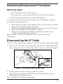
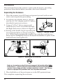
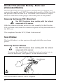
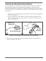
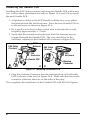
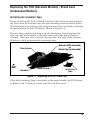
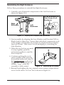
QuickScan® QS6000 Plus
Electronic Article Surveillance (EAS)
Installation Instruction Manual
Introduction
The EAS option enables QuickScan QS6000 Plus model scanners to
provide Electronic Article Surveillance (EAS) deactivation.
This document provides information and procedures to install a new
EAS Antenna Upgrade Kit, or to replace a malfunctioning loop antenna
already installed in the scanner.
The EAS upgrade or replacement of the loop antenna in the scanner
involves:
• Replacing the Scan Window with a new thinner Scan Window
and the EAS Loop Antenna;
• Replacing the Handle Printed Circuit Board (PCB) with one that
contains a connector for the EAS Antenna leads, and
• Replacing the Interface Cable with a special EAS Interface Cable.
The loop antenna connects to the store’s EAS System through this special
Interface Cable
Before installing the upgrade or replacing the EAS antenna, verify that
your EAS Upgrade Kit contains the following items shown in Figure 1.
Loop Antenna
1
Scan Window
To EAS System
EAS/Interface
Cable
1. Scan Window/
EAS Antenna.
2
2.
3
3. Insulation Tape Strip
4
4 . This Instruction Sheet
Handle PCB.
You should also have the correct
EAS/Interface cable that matches
your POS Terminal connection.
Figure 1. EAS Kit
1
Tools Required
You need the following tools to upgrade or replace the EAS
Antenna:
•
•
•
•
•
Torque Limiting Driver.
T8 Torx® bit.
Multimeter (or equivalent) to test for continuity.
ESD (ElectroStatic Discharge) protection as described below.
.050 hex driver
ElectroStatic Discharge Protection
To protect static sensitive circuitry, follow these ElectroStatic Discharge
(ESD) procedures when upgrading, or servicing an existing EAS antenna.
Figure 2 shows the ESD materials.
4
ESD Materials:
1
1. Anti-static tablemat
2
2. Anti-static wriststrap
3. Anti-static floormat
3
4. Earth Ground
Alerts you to use
ESD protection.
Figure 2. ESD Setup
ESD Procedures:
1. Connect the above ESD components together with a common
ground strap to eliminate any electrical potential.
2. Use the anti-static floor and table mats to neutralize the working
area (floors, carpeting, tables, etc.).
3. Use the anti-static wrist strap to eliminate buildup static charge
picked up from the environment (shoes on carpets, etc.).
4. Attach the anti-static ground clip to a known ground point.
PSC and the PSC logo are registered Trademarks of PSC INC. QS6000/6000 PLUS is
®
®
aTorx
trademark
owned by PSC,
Inc. Torx
is a registered
is a registered
trademark
of Camcar
Textron.trademark of Camcar Textron.
2
Installation/Replacement Procedures
Before you begin
1. Disconnect the Power to the Scanner.
2. Disconnect the scanner from the Point of Sale (POS) Terminal.
3. Place the scanner on its side on the ESD tablemat.
To Replace the EAS antenna or to install a new EAS antenna, use the
procedures described below to:
•
•
•
•
•
Disconnect and replace the Interface Cable (I/F) with a new cable.
Separate the Left and Right enclosures.
Remove and Replace the Handle PC Board with a new PC Board.
Remove and replace the Decoder PC Board.
Remove the original Scan Window and replace with a new
window and the EAS loop antenna.
Reference the QuickScan QS6000 Plus Service Manual for more
information.
Disconnecting the I/F Cable
The I/F Cable connects the scanner to the POS system and power supply.
1. Insert a .050” hex driver or bent paper clip into the CABLE RELEASE
hole, and press down to unlock the cable connector. Refer to Figure 3.
Paper Clip
Cable Release
Interface
Connector
Adapter Plug for
QS6000 Plus
I/F Cables
Figure 3. Disconnecting the Interface Cable.
2. Gently pull the cable connector from the scanner.
3. Disconnect the cable from the POS system (connections will vary
depending upon interface type.
This completes I/F Cable disconnection.
3
Enclosures
The enclosures house the scanner’s optics and electronics, providing
protection from dust & debris, moisture, shock and vibration.
Separating the Enclosure
1. Place the scanner on an ESD mat and ground yourself with an antistatic wrist strap before proceeding.
2. If you have not already done so, disconnect the AC/DC Adapter and I/F Cable as
described in previous sections.
3. Using a T-8 Torx® driver, remove and
retain the two screws accessible through
the Right Enclosure as shown in Figure 5.
4. Starting at the handle, begin separating the
Figure 5. Remove Screws
two enclosure halves as shown in Figure
6 A. While firmly grasping the window lip, carefully work the two
halves apart, attempting to leave all internal assemblies in place in the
Left Enclosure (see Figure 6 B).
A B
Figure 6. Separating the Enclosure
Under no circumstances should internal components be touched without FULL
ESD protection. Failure to follow the outlined ESD procedures could damage the
scanner’s laser diode and other sensitive electronics circuits. Any damage
related to improper ESD prodedures will void all product warranties.
5. Place both halves of the enclosures on to the ESD protected area.
This completes separating the enclosure.
4
Handle PCB
The Handle PCB contains the interface/power connection and houses
the trigger switch. On undecoded models, it also encompasses speaker,
LED and object detector circuitry. To install the EAS option, the Handle
PCB is replaced with the Handle PCB included in the EAS Upgrade Kit.
Removing the Handle PCB
1. Place the scanner on an ESD mat and ground yourself with an antistatic wrist strap before proceeding.
2. Remove the Right Enclosure as described in previous section.
Remember… under no circumstances should the internal
assemblies be touched without FULL ESD protection.
3. Lift up on the latch securing the Scan Engine-to-Handle PCB harness
as shown in Figure 7 and disconnect at the Handle PCB connector.
Note that on undecoded models, the Scan Engine-to-Handle PCB
harness will be narrower.
Latch Closed
Latch Open
Figure 7. Connecting/Disconnecting the Handle PCB (Decoded Models)
4. Lift the Handle PCB out of the enclosure and place on the ESD
protected area.
This completes the Handle PCB removal.
5
Decoder PCB (Decoded Models) / Blank Card
(Undecoded Models)
The Decoder PCB processes signals to and from the Scan Engine and
contains the speaker and LED. On undecoded models, a Blank Card fills
the position of the Decoder PCB. The Blank Card contains no components or connections and a plug is used in the place of the speaker.
Removing the Decoder PCB / Blank Card
Use ESD Procedures when working with the internal
components of the scanner.
With the scanner enclosure laid on it’s side, carefully lift the Decoder
PCB (or Blank Card) from the scanner and place on the protected area of
the ESD mat.
This completes Decoder PCB / Blank Card removal.
Scan Window
The Scan Window is a clear aperture through which the scan beam
passes.
Removing the Scan Window
Use ESD Procedures when working with the internal
components of the scanner.
To remove the Scan Window, slide the window from its slots in
the Left Enclosure. See Figure 8. Set the window aside.
Scan Window
Figure 8. Removing the Scan Window
The Scan Window removal is now complete.
6
Installing the EAS Antenna/Scan Window
To accommodate for the thickness of the EAS Loop Antenna, a thinner
Scan Window replaces the standard Scan Window. This new Scan
Window and the Loop Antenna are installed together into the Enclosure.
To install the EAS Loop Antenna and the new Scan Window, follow these
procedures:
1. Place the new Scan Window and the EAS Loop Antenna together as
shown in Figure 9 A.
2. While holding the Scan Window and the Antenna together, slide
them simultaneously into the window slot in the Left Enclosure as
shown in Figure 9 B.
EAS Loop
Antenna
Scan
Window
Scan Window
A B
Figure 9. Installing the Scan Window with EAS Loop Antenna
3. Locate the Loop Antenna wires along the left side of the handle as
shown in Figure 9 B, above.
7
Installing the Handle PCB
Installing the EAS Option requires replacing the Handle PCB with a new
one. Follow these procedures and refer to Figure 10 A and 10 B to install
the new Handle PCB.
1. Align the two holes in the PCB Handle with the two screw pillars
that extend from the Left Enclosure. Place the new Handle PCB on
to the enclosure as shown in Figure 10 A.
2. Tie a small service knot in the twisted wire to shorten the overall
length by approximately 1/2 inch.
3. Verify that the twisted wire leads from the EAS Antenna are not
trapped beneath the Handle PCB. The wire should lay in the
enclosure adjacent to the Handle PCB as shown in Figure 10 B.
EAS Cable
(Twisted)
EAS Loop
Antenna
EAS Cable
(Twisted)
Left
Enclosure
Left
Enclosure
Handle PCB
Inset
A
Antenna
Connector
B
Figure 10. Installing the Handle PCB
4. Plug the Antenna Connector into the Antenna plug on the Handle
PCB as shown in the inset of Figure 10 B. Make sure the tabs on the
connector slide into the slots on the sides of the plug.
This completes the installation of the Handle PCB with the EAS Option.
8
Replacing the PCB (Decoded Models) / Blank Card
(Undecoded Models)
Installing the Insulated Tape
Before installing the PCB or Blank Card into the Left Enclosure, Insulating Tape must be installed onto the tab extending from the metal shield.
This Insulated Tape protects the Loop Antenna from accidently touching
the metal shield on the PCB board. (Refer to Figure 11).
Remove the protective backing from the Insulating Tape and place the
tape onto the metal shield so that the entire tab of the metal shield is
covered. Take care not to extend tape into the clear part of the Scanner
Window so that it obstruct the scanning beam.
Decoder PCB (decoded)
or
Blank Card (undecoded)
Scan Engine
Harness
Metal Shield
Insulating
Tape
Figure 11. Replacing the PCB / Blank Card
Once the Insulating Tape is mounted to the metal shield, the PCB Board,
or Blank Card, is ready to install into the Left Enclosure.
9
Reinstalling the Decoder PCB / Blank Card into the Enclosure.
To reinstall the PCB / Blank Card into the Left Enclosure:
1. Align the edges with their corresponding slots and slide the
PCB or Blank Card assembly into place in the Left Enclosure.
Ensure that all components (especially the speaker and
Decoder PCB) are correctly seated in their appropriate positions. Reference Figure 12.
2. Verify that the EAS twisted wire from the Loop Antenna lays
beneath the metal shield of the PSB / Blank card and the
enclosure, and lays in the enclosure besides the Handle PCB.
PCB / Blank Card
Left
Enclosure
Metal Shield
EAS Cable
(Twisted)
Wire Harness
Insulating Tape
EAS Loop
Antenna
Handle PCB
Figure 12. Reinstalling the PSB / Blank Card
3. Insert the Scan Engine-to-Handle PCB wire harness into its
connector as shown in Figure 7, and, when fully seated, press
down on the latch to secure it in place.
Replacing the Decoder PCB or Blank Card is now complete.
10
Reinstalling the Right Enclosure
Follow these procedures to reinstall the Right Enclosure:
1. Carefully seat all internal components in the Left Enclosure as
shown in Figure 13 A.
Press downward on
Rear Snap of Left
Enclosure
Right
Enclosure
Left
Enclosure
A
B
Figure 13. Aligning and Snapping the Enclosures
2. Start assembly by aligning the Scan Window and Decoder PCB (or
Blank Card) in their slots. Ensure that individual components such
as the Trigger and Speaker (if present) are aligned and not interfering with closure. Take care to avoid smudging or scratching the
Scan Window.
3. When the two halves are ready
to snap together, push the
enclosurestogether to seat the
front snap first.
4. Continue pushing the enclosures together while pressing
downward on the rear snap of
the Left Enclosure as shown in
Figure 13 B. You will hear an
audible “snap” when the
assembly is fully seated.
Figure 14. Reinstalling the Handle
5. Reinstall and tighten the two original screws using a torque driver
set to 5 in-lb with a T-8 Torx® bit as shown in Figure 14.
11
DO NOT overtighten the screws. Overtightening will result
in damage to the enclosures.
This completes the installation of EAS Option. Refer to the following
section for procedures to install the scanner to the EAS System. .
Connecting the EAS Antenna to the EAS
System
If not already done so, disconnect power to the scanner unit and powerdown the Point of Sales Terminal (POS) and the EAS System. Follow the
procedures below and refer to Figure 15 to install the scanner to the
store’s EAS System
1. Scanner Interface
Connection
1
2
2. Host Terminal
Conection
$4.50
$2.79
$3.99
3. EAS Connection
(Two wires)
3
4
4. AC/DC Adapter
(If not Power Off
Terminal).
Figure 15. Installing the EAS Antenna to the EAS System
1. Reconnect the scanner end of the Interface Cable into the scanner.
2. Connect the POS end of the Interface Cable into the POS terminal.
3. Connect the EAS antenna to the EAS System via the two wires
extending from the Interface Cable (near the POS terminal end).
4. Reconnect the AC/DC adapter, if not supplied by the POS Terminal, to the scanner.
Installation of the EAS option is now complete. Power-up the POS
according to the POS procedures. The system in now operational.
12
Troubleshooting
Scanners equipped with the EAS option are fittedwith a special loop
antenna inside the Scan Window. The loop antenna connects to the
store’s EAS System via two wires bundled within the Interface Cable.
Pins 1 and 10 on the Interface connector feed the antenna signal to the
store’s EAS System, and a special cable couples the EAS antenna to the
EAS control box.
Replacing the antenna or installing a new one, involves replacing the
entire Scan Window/Loop Antenna as described earlier.
EAS Problem Isolation
Use the following procedure to isolate EAS loop antenna problems.
Figure 16 provides a schematic diagram of the EAS Loop Antenna, and
Figure 17 shows the Test Setup using a multimeter to test for continuity.
1. Disconnect power from the scanner. Power down the EAS System
and POS Terminal using your power-down procedures.
2. Disconnect the scanner from the store’s EAS System by disconnecting the EAS System at the two wires exiting from the
scanner’s Interface Cable.
3. Disconnect the scanner from the POS Terminal.
4. With the interface cable still connected to the scanner, use the
OHM setting on a multimeter to check the loop antenna and
cable for continuity by touching the meter probes to the two
EAS wires that exit from the Interface Cable. (Reference
Figure 16).
• If the loop antenna and cable are continuous (resistance less
than 10 ohms), the antenna is operational. No problem found.
• If the loop and cable are not continuous, go to step 5.
13
EAS Loop
Antenna
Test
Leads
OHMS
1
Handle PCB
To EAS
EAS Plug
System
RJ
Connector
Multimeter
Set to OHMS
To
POS
10
Interface Cable
Figure 16. EAS Schematic
RJ
Connector
From EAS
Loop Antenna
Interface
Cable *
*Your I/F cable connection may differ from
the illustraion due to yor POS Terminal.
To POS
Figure 17. EAS Test Setup
5. Remove the Interface cable (I/F) from the scanner. Inspect the
Interface cable and I/F connector on the scanner for damage. Verify
pins 1 and 10 of the Scanner I/F connector are positioned to engage
the RJ plug on the scanner side of the I/F cable.
6. Using the OHM setting on the Multimeter, check for continuity
(Resistance less than 10 ohms) from the two EAS wires extending
from the POS end of the cable to pins 1 and 10 on the RJ connector at
the scanner end of the cable.
• If continuity exists then the I/F Cable is functional. Go to step 7.
• If there is no continuity, replace the I/F cable with a known good
one.
7. Check the loop antenna at pins 1 and 10 of the scanner I/F
connector with the multimeter for continuity.
• If not continuous, replace the EAS assembly using the
procedures described earlier.
This completes the procedures to isolate problems with scanners having
the optional EAS antenna.
14
NOTES
15
Australia
Japan
Datalogic Scanning Pty Ltd
Datalogic Scanning KK
North Ryde, Australia
Shinagawa, Tokyo, Japan
Telephone: [61] (2) 9870 3200
Telephone: 81 (0)3 3491 6761
Fax: [61] (2) 9878 8688
Fax: 81 (0)3 3491 6656
France and Benelux
Latin America
Datalogic Scanning Sarl
Datalogic Scanning, Inc
LES ULIS Cedex, France
Miami, Florida, USA
Telephone: [33].01.64.86.71.00
Telephone: (305) 591-3222
Fax: [33].01.64 46.72.44
Fax: (305) 591-3007
Germany
Spain and Portugal
Datalogic Scanning GmbH
Datalogic Scanning Sarl Sucursal en España
Darmstadt, Germany
Madrid, Spain
Telephone: 49 (0) 61 51/93 58-0
Telephone: 34 91 746 28 60
Fax: 49 (0) 61 51/93 58 58
Fax: 34 91 742 35 33
Italy
United Kingdom
Datalogic Scanning SpA
Datalogic Scanning LTD
Vimercate (MI), Italy
Watford, England
Telephone: [39] (0) 39/62903.1
Telephone: 44 (0) 1923 809500
Fax: [39] (0) 39/6859496
Fax: 44 (0) 1923 809 505
www.scanning.datalogic.com
Datalogic Scanning, Inc.
959 Terry Street
Eugene, OR 97402
Telephone: (541) 683-5700
Fax: (541) 345-7140
©1998 - 2007 Datalogic Scanning, Inc.
R44-2799 (Rev. A)
5/07


![Installation Manual [PDF 2.5 MB]](http://vs1.manualzilla.com/store/data/006019755_1-cd5e1ac77f4b7b55781d3fd4e75d7494-150x150.png)