1
US008437899B2
(12) Ulllted States Patent
(10) Patent N0.:
Jaenke et a].
(54)
US 8,437,899 B2
(45) Date of Patent:
METHOD AND APPARATUS FOR
PROGRAMMING PARAMETERS OF A
POWER DRIVEN WHEELCHAIR FOR A
(51)
*May 7, 2013
(52)
Int. Cl.
B60L 9/00
US. Cl.
(58)
USPC ............................. .. 701/22; 701/36; 180/658
Field of Classi?cation Search .................. .. 701/22,
PLURALITY OF DRIVE SETTINGS
(75) Inventors: Bruce A. Jaenke, Parma, OH (US);
Gary E. Chopcinski, North Ridgeville,
(2006.01)
701/36; 180/658
See application ?le for complete search history.
OH (U S)
(56)
References Cited
(73) Assignee: Invacare Corporation, Elyria, OH (US)
(*)
Notice:
US. PATENT DOCUMENTS
1,114,943 A
10/1914 Walker
2,759,525 A
8/1956 Reis
Subject to any disclaimer, the term ofthis
patent is extended or adjusted under 35
U.S.C. 15403) by 0 days.
(Continued)
Tlhi's patent is subject IO a {61111111211 d15-
FOREIGN PATENT DOCUMENTS
C almer'
(21)
Appl. N0.: 13/430,011
DE
3923937
1/1990
EP
0345785
12/1989
(Continued)
(65)
Prior Publication Data
US 2012/0185114A1
Of?ce action from New Zealand Application No. 565,935 dated Feb.
18, 2011.
Jul. 19,2012
(Continued)
Related US Application Data
_
(63)
(60)
_
_
Primary Examiner * Mark Hellner
_
(74) Attorney, Agent, or Firm * Calfee, Halter & Griswold
Cont1nuat1on of appl1cat1on No. 12/064,697, ?led as
application No. PCT/US2006/033963 on Aug. 31,
2006, noW Pat. No. 8,145,373.
LLP
Provisional application No. 60/712,987, ?led onAug.
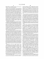
A method of programming parameters of a power driven
Wheelchair for a plurality of drive modes comprises: display
(57)
31, 2005, provisional application No. 60/727,005,
ABSTRACT
?led on Oct. 15, 2005, provisional application No.
60/726,983, ?led on Oct. 15, 2005, provisional
application No. 60/726,666, ?led on Oct. 15, 2005,
provisional application No. 60/726,981, ?led on Oct.
eters for a plurality of drive modes of the Wheelchair; select
ing a Wheelchair parameter for a drive mode from the dis
15, 2005, provisional application No. 60/726,993,
played menu image; and programming the setting of the
?led on Oct. 15, 2005, provisional application No.
60/727,249, ?led on Oct. 15, 2005, provisional
application No. 60/727,250, ?led on Oct. 15, 2005.
selected Wheelchair parameter to a desired setting.
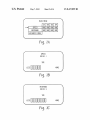
ing a menu image on an interactive display screen, the menu
image including settings of a plurality of Wheelchair param
19 Claims, 14 Drawing Sheets
16
A
MAIN MENU
SPEED
RESPONSE
ADVANCED MENU
D1 D2 D3 D4
357. 902 90% 9DZ
QUZ 90% 90% 90K
\
j
K
SPEED
\
DRIVE 1
35%
LESSUUUUUU
Q
M
US 8,437,899 B2
Page 2
U.S. PATENT DOCUMENTS
3,454,305
4,736,921
4,779,884
4,951,766
5,033,000
5,157,768
5,187,797
5,197,559
5,234,066
5,245,558
5,248,007
5,261,715
5,299,824
5,516,021
5,547,038
5,555,949
5,647,520
5,718,442
5,794,730
5,899,526
5,961,561
6,068,280
6,154,690
6,170,598
6,290,011
6,354,390
6,409,265
6,425,635
6,688,571
6,816,762
6,819,981
6,832,745
6,866,107
6,868,931
6,871,122
6,874,591
6,926,106
6,938,923
6,974,194
6,976,699
6,989,642
6,991,292
7,003,381
7,083,019
7,148,638
7,159,181
7,171,288
7,262,762
7,296,312
7,310,776
7,374,679
7,403,844
7,461,897
7,635,164
7,668,634
8,065,051
8,073,585
8,073,588
8,127,875
8,145,373
8,315,753
2003/0001875
2003/0109973
2004/0002305
2004/0252341
2004/0259591
2005/0195173
2005/0236196
2005/0236208
2005/0236217
2007/0050096
2007/0050111
2007/0056781
2007/0074917
2008/0030463
2008/0249694
2009/0121532
>
7/1969
4/1988
10/1988
8/1990
7/1991
10/1992
2/1993
3/1993
8/1993
9/1993
9/1993
11/1993
4/1994
5/1996
8/1996
9/1996
7/1997
2/1998
8/1998
5/1999
10/1999
5/2000
11/2000
1/2001
9/2001
3/2002
6/2002
7/2002
2/2004
11/2004
11/2004
12/2004
3/2005
3/2005
3/2005
4/2005
8/2005
9/2005
12/2005
12/2005
1/2006
1/2006
2/2006
8/2006
12/2006
1/2007
1/2007
8/2007
11/2007
12/2007
5/2008
7/2008
12/2008
12/2009
2/2010
11/2011
12/2011
12/2011
3/2012
3/2012
11/2012
1/2003
6/2003
1/2004
12/2004
12/2004
9/2005
10/2005
10/2005
10/2005
3/2007
3/2007
3/2007
4/2007
2/2008
10/2008
5/2009
Gilmour
2009/0153370 A1
2010/0082182 A1
2012/0064502 A1
Zane et al.
Minati
Basedow et al.
Littlejohn et al.
Hoeber et al.
Nielsen et al.
Garin et al.
Ahsing et al.
Hachey
Watkins et al.
Blatt et al.
Roberts et al.
Douglass
Madwed
Stallard et al.
McDaid
Alexander et al.
Kamen
LaPointe et al.
Wake?eld
Torres
Coleman
Furukawa
Langaker et al.
Uchiyama et al.
Koerlin et al.
Pulver
Pauls
Hensey et al.
Wake?eld, 11 et al.
Lindsay
HeinZmann et al.
Morrell et al.
Wake?eld, II
6/2009 Cooper et al.
4/2010 Griggs et al.
3/2012 Chopcinski
FOREIGN PATENT DOCUMENTS
EP
EP
GB
JP
JP
JP
JP
WO
WO
WO
WO
WO
0436103
1148394
2222701
2008-194183
2009-261472
2009-078028
2010-017354
03034967
2005032924
2005037168
2005039473
2005039930
7/1991
10/1991
3/1990
8/2008
1/2009
4/2009
1/2010
5/2003
4/2005
4/2005
5/2005
5/2005
OTHER PUBLICATIONS
Response from New Zealand Application No. 565,935 dated Apr. 15,
2011.
Of?ce action from New Zealand Application No. 591,829 dated Mar.
28, 2011.
Of?ce action from New Zealand Application No. 591,831 dated Mar.
28, 2011.
Of?ce action from New Zealand Application No. 592,271 dated Apr.
20, 2011.
Of?ce action from New Zealand Application No. 592,317 dated Apr.
21, 2011.
Response to Of?ce Action from Australian Application No.
2006284749 dated Apr. 30, 2012.
Response from US. Appl. No. 11/513,740 dated Jul. 21, 2011.
Of?ce action from US. Appl. No. 11/513,740 dated Oct. 18, 2011.
Morrell et al.
Applicant-requested Interview Summary from US. Appl. No.
Richey, 11 et al.
11/513,740 dated Jan. 27, 2012.
Statement of Substance of Interview from US. Appl. No. 1 1/513,740
dated Feb. 23, 2012.
Final Of?ce Action from US. Appl. No. 11/513,740 dated Apr. 13,
Mulhern et al.
Schreiber et al.
Koerlin
Wake?eld, 11 et al.
Kasten
2012.
Of?ce action from US. Appl. No. 11/514,016 dated Feb. 22, 2010.
Response from US. Appl. No. 11/514,016, ?led Jul. 21, 2010.
Notice ofAllowance from US. Appl. No. 11/514,016 dated Sep. 30,
Wake?eld, II
Chiou et al.
Wake?eld, II
Mansell et al.
Wake?eld, II
2010.
Comments on Statement of Reasons for Allowance from US. Appl.
McAlindon
Menkedick et al.
Mansell et al.
No. 11/514,016 dated Oct. 29, 2010.
Notice ofAllowance from US. Appl. No. 11/514,016 dated Jan. 19,
Huang et al.
Chopcinski et al.
Notice ofAllowance from US. Appl. No. 11/514,016 dated May 5,
Kruse et al.
Torres et al.
Mansell et al.
Response from US. Appl. No. 11/514,016 dated Aug. 4, 2011.
Notice ofAllowance from US. Appl. No. 11/514,016 dated Sep. 12,
2011.
2011.
Chopcinski et al.
2011.
Jaenke et al.
Peters et al.
Mattes
Of?ce action from US. Appl. No. 11/513,854 dated Apr. 15, 2009.
Response from US. Appl. No. 11/513,854 dated Oct. 15, 2009.
Of?ce action from US. Appl. No. 11/513,854 dated Feb. 3, 2010.
Response from US. Appl. No. 11/513,854 dated Aug. 3,2010.
Notice ofAllowance from US. Appl. No. 11/513,854 dated Jul. 18,
Jaenke et al.
................. .. 701/22
Meyer
Black
Hensey et al.
Byman-Kivivuori et al.
Adachi et al.
Grams et al.
McKay
Runkles et al.
Runkles et al.
Koerlin et al.
Mattes et al.
Mattes et al.
Mattes et al.
Jaenke et al.
Forest
Jaenke et al.
Kruse et al.
2011.
Notice of Allowance from US. Appl. No. 11/513,854 dated Oct. 4,
2011.
US. Appl. No. 11/511,606, Notice ofAllowance and Fees Due with
Notice of Allowability, 5 pages, mailed May 8, 2008.
Response to Of?ce action from US. Appl. No. 11/511,606 dated Jan.
8, 2008.
Of?ce Action from US. Appl. No. 11/511,606, 5 pages, mailed Sep.
13, 2007.
Response to Of?ce action from US. Appl. No. 11/511,606 dated
Aug. 24, 2007.
US. Appl. No. 11/511,606, Final Of?ce Action, 5 pages, mailed Jun.
7, 2007.
Response to Of?ce action from US. Appl. No. 11/511,606 submitted
Mar. 21, 2007.
US 8,437,899 B2
Page 3
U.S. Appl. No. 11/511,606, Non-?nal Of?ce Action, 4 pages, mailed
Dec. 21, 2006.
Of?ce action from U.S. Appl. No. 11/513,780 dated Jan. 27, 2011.
Response from U.S. Appl. No. 11/513,780 dated Apr. 27, 2011.
Of?ce action from U.S. Appl. No. 11/513,780 dated Aug. 2, 2011.
Response with RCE from U.S. Appl. No. 11/513,780 dated Feb. 2,
2012.
Of?ce Action from U.S. Appl. No. 11/513,780 dated Mar. 30,2012.
Response to Of?ce action from U.S. Appl. No. 11/513,746 dated Oct.
27, 2008.
Of?ce action from U.S. Appl. No. 11/513,746 dated Jan. 15, 2009.
Of?ce action from U.S. Appl. No. 11/513,802 dated Aug. 7, 2009.
Response from U.S. Appl. No. 11/513,802 dated Dec. 3, 2009.
Of?ce action from U.S. Appl. No. 11/513,802 dated Mar. 19, 2010.
Response from U.S. Appl. No. 11/513,802 dated Aug. 19,2010.
Of?ce action from U.S. Appl. No. 11/513,802 dated Oct. 6,2010.
Response from U.S. Appl. No. 11/513,802 dated Feb. 4, 2011.
Of?ce action from U.S. Appl. No. 11/513,802 dated Apr. 14, 2011.
Response from U.S. Appl. No. 11/513,802 dated Jul. 14, 2011.
Notice ofAllowance from U.S. Appl. No. 11/513,802 datedAug. 25,
201 1.
Notice of Allowance from U.S. Appl. No. 11/513,802 dated Oct. 3,
201 1.
Of?ce action from U.S. Appl. No. 11/513,750 dated Nov. 23, 2009.
Response from U.S. Appl. No. 11/513,750 dated May 21,2010.
Notice ofAllowance from U.S. Appl. No. 11/513,750 dated Dec. 2,
2010.
Notice ofAllowance from U.S. Appl. No. 11/513,750 dated Jan. 20,
201 1.
Notice ofAllowance from U.S. Appl. No. 11/513,750 dated May 5,
Int’l App. No. PCT/US06/33963, Written Opinion of the
tional Searching Authority, mailed May 4, 2007, 6 pages.
Int’l App. No. PCT/US06/33964, International Search
mailed May 4, 2007, 3 pages.
Int’l App. No. PCT/US06/33964, Written Opinion of the
tional Searching Authority, mailed May 4, 2007, 10 pages.
Int’l App. No. PCT/US06/33971, International Search
Interna
Report,
Interna
Report,
mailed Mar. 9, 2007, 4 pages.
Int’l App. No. PCT/US06/33971, Written Opinion of the Interna
tional Searching Authority, mailed Mar. 9, 2007, 6 pages.
Int’l App. No. PCT/US06/33973, International Search Report,
mailed Mar. 16, 2007, 3 pages.
Int’l App. No. PCT/US06/33973, Written Opinion of the Interna
tional Searching Authority, mailed Mar. 16, 2007, 5 pages.
Int’l App. No. PCT/US06/33978, International Search Report,
mailed Jun. 5, 2007, 7 pages.
Int’l App. No. PCT/US06/33978, Invitation to Pay Additional Fees
and Communication Relating to the Results of the Partial Interna
tional Search, mailed Apr. 5, 2007, 8 pages.
Int’l App. No. PCT/US06/33978, Written Opinion of the Interna
tional Searching Authority, mailed Jun. 5, 2007, 8 pages.
Int’l App. No. PCT/US06/34149, International Search Report,
mailed Jun. 8, 2007, 3 pages.
Int’l App. No. PCT/US06/34149, Written Opinion of the Interna
tional Searching Authority, mailed Jun. 8, 2007, 7 pages.
Invacare CorporationiBrochurei"Invacare Tarsys Series Powered
Seating Systems”, Form No. 00-313, rev. Sep. 2002, 16 pgs.
Invacare CorporationiBrochurei"Storm Series Power Wheel
chairs including Fomula CG Powered Seating, MK6i Electronics”,
16 pgs., 2006, Form No. 06-040.
Invacare CorporationiBrochurei"Invacare Storm Series TDX
201 1.
Power Wheelchairs, including Formula Powered Seating”, Form No.
Notice ofAllowance from U.S. Appl. No. 11/513,750 dated Oct. 12,
03-018, rev. Jul. 2004, 32 pgs.
201 1.
Katsura et al., “Semiautonomous wheelchair based on quarry of
environmental information”, IEEE Translations on Industrial Elec
Invacare, Owner’s Operator and Maintenance Manual, 3G Storm
Series Wheelchair Bases, Arrow RWD, Torque SP RWD, Ranger X
tronics, vol. 53, issue 4, Digital Object Identi?er 10.1109/TIE.2006.
878294, pp. 1373-1382, published 2006.
Invacare, Owner’s Operator and Maintenance Manual, Formula, CG
Powered Seating Tilt Only, 48 pgs., Part No. 1143155, dated Jun. 30,
Sasaki et al., “Development of a new adaptation system for a manual
wheelchair based on human body function”, MHS ’07 International
Linak, Product Data Sheet, Actuator LA30, 8 pgs, Chapter 2.1, copy
Symposium on Micro-NanoMechatronics and Human Science, Digi
right May 2002.
tal Object Identi?er, 10.1109/MHS.2007.4420902, pp. 478-484,
published 2007.
Seong-Pal Kang, “A hand gesture controlled semi-autonomous
Linak, Product Data Sheet, Actuator LA31, 8 pgs, Chapter 5.8.2,
RWD, dated Jun. 30,2006, 88 pgs., Part No. 1143151.
2006.
copyright May 2005.
MK5 Electronics Top 10 Application Features, 2005 Spring Update,
wheelchair”, IEEE/RSJ Intl Conf on Intelligent Robots and Systems,
10 pgs.
Digital Object Identi?er: 10.1109/IROS.2004.1389968, pp. 3565
3570, vol. 4, published 2004.
Tanimoto et al., “Measurement of wheelchair position for analyzing
transfer motion for SCI patient”, Imaging Systems and Techniques,
IST ’07, IEEE International Workshop on Digital Object Identi?er,
10.1009/IST.2007.379605, pp. 1-6, published 2007.
Paula, Taking sensors out of motors, Mechanical Engineering, The
Dynamic, Actuator Remote Control Module DX-ARC5 Installation
Manual, copyright Jun. 2004, 10 pgs.
Dynamic, DX Attendant Control Unit (ACU) Installation Manual,
No. 60013, issue 4, Nov. 1998, 30 pgs.
American Society of Mechanical Engineers, www.memagazineorg/
backissues/january98/ features/ sensout/ sensout.html, printed Aug.
16, 2006, 5 pgs (1998).
PG Drives TechnologyiR-Net Rehab-Powerchair Control System
(Presentation), 30 pages.
QR-ED Owners’s Manual, Quickie Enhanced Display, Sunrise
Medical, Inc., Longmont,Colorado, 10519 Rev. A, 2006 (51 pages).
Quantum Rehab Innovative Rehab Solutions, a division of Pride
Mobility Products Corp., one page brochure, Q-Logic Drive Control
Dynamic, DX Dolphin Remote (DX-Rem34) Installation Manual,
System, QLogiciMar. 13, 2006.
No. 60025, issue 5, Jan. 1999, 69 pgs.
Quantum Rehab Innovative Rehab Solutions, a division of Pride
Dynamic, DX Power Module (PMB, PMBl, PMB2, PMB-S) Instal
Mobility Products Group, Q controls, page from http://www.
lation Manual, No. 63824, issue 2, Jul. 1998, 85 pgs.
pridemobility.com/quantum/Electronics/QiControls/qicontrols.
Dynamic, DX Remote Joystick Module (RJM) Installation Manual,
No. 60014, iss. 4, Apr. 1997, 13 pgs.
Dynamic, DX Two Actuator Module (TAM) Installation Manual, No.
60026, issue 5, Jul. 1998,45 pgs.
Dynamic, DX-GB, The Complete Gearless Brushless DC Control
System brochure, 2 pgs.
Dynamic, DX-REMG90, DX-REMG90A, DX-REMG90T Master
Remotes Installation Manual, GBK64048, issue 1, Jan. 2005, 61 pgs.
Flash, New and Notable Product Design, p. 28 from Design News
Oct. 10,2005.
In?neon
Technologies,
“XC164CS
16-Bit
Single-Chip
Microcontroller”, Data Sheet, V2.1, Jun. 2003, 71 pgs.
Int’l App. No. PCT/US06/33963, International Search Report,
mailed May 4, 2007, 3 pages.
html, printed Jun. 9, 2006, copyright 1995-2006.
Quickie HHP Programming Tree, Sunrise Medical, Inc., Longmont,
Colorado (7 pages).
Service Manual, Quickie Rhythm & Groove, Sunrise Medical, Inc.,
Longmont, Colorado, 014061 Rev. A, 2006 (104 pages).
Specialty Control Set Up & Programming Guide, QR-SCM Owner’s
Manual, Quickie Electronics Platform powered by Delphi, Sunrise
Medical, Inc., Longmont, Colorado, 101748 Rev. A, 2006 (15 pages).
Teknic, Inc., “The price/performance leader for OEM machine auto
mation”, Investigating Servo Architectures, 14 pgs. printed Aug. 15,
2006 from http://wwwteknic.com/systems/, copyright 2006.
Of?ce action from U.S. Appl. No. 11/513,740 dated Feb. 4, 2010.
Response from U.S. Appl. No. 11/513,740 dated Jul. 6, 2010.
Of?ce action from U.S. Appl. No. 11/513,740 dated Oct. 4, 2010.
US 8,437,899 B2
Page 4
Response from U.S. Appl. No. 11/513,740 dated Feb. 4, 2011.
Of?ce action from U.S. Appl. No. 11/513,740 dated Apr. 21, 2011.
Response from New Zealand Application No. 565,930 dated May 5,
Asakawa et al., “Experiment on operating methods of an electric
Of?ce action from New Zealand Application No. 565,930 dated May
26, 201 1.
Response from New Zealand Application No. 565,930 dated Jun. 24,
wheelchair for a system of detecting position and direction”, Robot
ics and Biomimetics, ROBIO 2007, IEEE Int’l Conf on Digital
Object Identi?er, 10.1109/ROBIO.2007.4522345, pp. 1260-1265
(2007).
Barea, R., et al., “EOG guidance of a wheelchair using nerual net
works”, Proceedings 15th Intl Conf. on Pattern Recognition, vol. 4,
Digital Object Identi?er 10.1109/ICPR.2000.903006, pp. 668-671,
published 2000.
Cooper et al., “Analysis of position and isometric joysticks for pow
201 1.
201 1.
Of?ce action from New Zealand Application No. 565,931 dated Oct.
8, 2009.
Response from New Zealand Application No. 565,931 dated Mar. 7,
201 1.
Of?ce action from New Zealand Application No. 565 ,931 dated Mar.
25, 201 1.
Response from New Zealand Application No. 565,931 dated May 4,
ered wheelchair driving”, Biomedical Engineering, IEEE Transac
tions on Digital Object Identi?er, vol. 47, issue 7, 10.1109/10.
846684, published 2000, pp. 902-910.
Jones et al., “Powered wheelchair driving performance using force
201 1.
and position-sensing joysticks”, Bioengineering Conference, Pro
201 1.
ceedings of the IEEE 24th Annual Northeast, Digital Object identi
?er, 10.1109/NEBC.1998.664901, pp. 130-132, published 1998.
Of?ce action from New Zealand Application No. 565,932 dated Mar.
29, 201 1.
Of?ce action from U.S. Appl. No. 12/064,697 dated Jun. 22, 2011.
Amendment with Terminal Disclaimer from U.S. Appl. No.
201 1.
Of?ce action from New Zealand Application No. 565,932 dated Oct.
12, 2009.
Response from New Zealand Application No. 565 ,932 dated Mar. 21,
Response from New Zealand Application No. 565 ,932 dated May 13,
201 1 .
Of?ce action from New Zealand Application No. 565,933 dated Sep.
28, 2009.
Response from New Zealand Application No. 565,933 dated Feb. 16,
Of?ce action from U.S. Appl. No. 13/228,677 dated Feb. 2, 2012.
Amendment from U.S. Appl. No. 13/228,677 dated May 2, 2012.
Supplemental Amendment from U.S. Appl. No. 13/228,677 dated
Of?ce action from New Zealand Application No. 565,933 dated Feb.
28, 201 1.
12/064,697 dated Sep. 22, 2011.
Notice ofAllowance from U.S. Appl. No. 12/064,697 dated Nov. 23,
201 1.
May 30, 2012.
Response from New Zealand Application No. 565 ,933 dated Apr. 18,
Examiner Initiated Interview Summary from U.S. Appl. No.
13/228,677 dated Jun. 5,2012.
Notice ofAllowance from U.S. Appl. No. 13/228,677 dated Jun. 5,
201 1.
2012.
Of?ce action from Australian Application No. 20062 846 87 dated Jul.
26, 201 1.
Of?ce action from Australian Application No. 20062 84747 dated Jul.
Of?ce action from New Zealand Application No. 565,934 dated Oct.
12, 2009.
Response from New Zealand Application No. 565,934 dated Mar. 7,
201 1.
Of?ce action from New Zealand Application No. 565,934 dated Mar.
28, 201 1.
1, 201 1 .
Response from New Zealand Application No. 565 ,934 dated May 13,
Exam Report from Australian Application No. 2006284748 dated
201 1.
Aug. 29, 2011.
Apr. 28, 2011.
Of?ce action from New Zealand Application No. 565,935 dated Oct.
5, 2009.
Response from New Zealand Application No. 565,935 dated Feb. 4,
Of?ce action from Australian Application No. 20062 84741 date May
201 1.
Of?ce action from Australian Application No. 2006284749 dated
9, 201 1 .
Second Examination Report from New Zealand Application No.
Response to Of?ce Action from Australian Application No.
2006284741 dated May 17,2012.
Of?ce action from Australian Application No. 2006284753 dated Jul.
22, 201 1.
Exam Report from Australian Application No. 2006284768 dated
591,831 dated Aug. 16,2012.
Response to First Of?ce Action from EP Application No. 068 1 3984 .9
dated Oct. 18, 2012.
Of?ce Action from New Zealand Application No. 592,271 dated Nov.
16, 20 12.
Sep. 8, 2011.
Response to First Examiners Report from Australian Application No.
First Examiners Report from Australia Patent Application No.
2009230975 dated Nov. 24, 2010.
Response from Australia Patent Application No. 2009230975 dated
Nov. 30, 2011.
First Of?ce Action from EP Application No. 068139849 dated Apr.
24, 2012.
2006284687 dated Dec. 19, 2012.
Response to Of?ce Action from New Zealand Appl. No. 591,831
dated Nov. 12,2012.
First Of?ce Action in CA Application No. 2,614,744 dated Feb. 1,
First Of?ce Action from EP Application No. 068 14005 .2 dated Nov.
2013.
2, 201 1 .
First Of?ce Action from CA Application No. 2,615,091 dated Jan. 30,
Response from EP Application No. 068140052 dated May 4, 2012.
Of?ce action from New Zealand Application No. 565,929 dated Oct.
8, 2009.
Response from New Zealand Application No. 565,929 dated Mar. 7,
2013.
201 1 .
2013.
Of?ce action from New Zealand Application No. 565 ,929 dated Mar.
25, 201 1.
2013.
Response from New Zealand Application No. 565 ,929 dated May 11,
2013.
First Of?ce Action from CA Application No. 2,615,084 dated Feb. 1,
First Of?ce Action from CA Application No. 2,614,752 dated Feb. 5,
2013.
First Of?ce Action in CA Application No. 2,616,325 dated Feb. 4,
First Of?ce Action in CA Application No. 2,616,332 dated Feb. 5,
Of?ce action from New Zealand Application No. 565,930 dated Oct.
7, 2009.
Response from New Zealand Application No. 565,930 dated Feb. 22,
Response to Of?ce Action from AU Application No. 2006284747
dated Feb. 26, 2013.
Of?ce Action for U.S. Appl. No. 13/311,140 dated Jan. 10,2013.
Of?ce action from U.S. Appl. No. 13/412,034 dated Mar. 19, 2013.
First Of?ce Action in CA Application No. 2,615,087 dated Mar. 1,
201 1 .
2013.
201 1 .
Of?ce action from New Zealand Application No. 565 ,930 dated Mar.
10, 201 1 .
* cited by examiner
US. Patent
May 7, 2013
Sheet 1 0f 14
US 8,437,899 B2
_/
/‘l6
\14
\
f
[E E]
‘1] //-l8
EJEEIEI
U]
33
f
Z
as
22
MEMORY
A
EEPROM
D
24
MICROCONTROLLER
SEC/
(3
ZOJ
Fig.1
‘1m
US. Patent
May 7, 2013
{a
Sheet 2 0f 14
A N
US 8,437,899 B2
M0 Il/o0 muo D0193Z2. D94%W4
/m
MN
0
1
.
U
S
0
O
‘
A
RV am
SENPSEDIEMU
AD A
UI
Fig. 1A
SPEED
DRIVE 1
35%
MORE
Fig. 15
L?ssuunnunndn
Fig. 1C
MORE ]
US. Patent
May 7, 2013
Sheet 3 0f 14
17
{a
N
US 8,437,899 B2
M039£172 muhUo D9 3Z2 D94m
0N
M
N
AU
0
UN
5
0
A
‘
RV SME
SEANPnSCEF.EOU
U .l.
SPEED
DRIVE I
357.,
MORE
Fig. 1D
US. Patent
May 7, 2013
US 8,437,899 B2
Sheet 4 0f 14
16
MAIN MENU
-—>
D1 D2 D3 D4
35% 357.. 3570 35%
SPEED
RESPONSE
90X 90% 907., 907.,
ADVANCED MENU
SPEED
ALL DRIVES
35%
LESSUUUUUU
Fig. 1E
MORE
US. Patent
May 7, 2013
Sheet 5 0f 14
US 8,437,899 B2
16
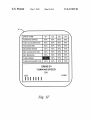
DRIVE NAME
D1
D2
D3
D4
FQRWARD SPEED
95%
95%
95%
95%
FWD ACCELERATIQN
85%
85%
85%
85%
FWD BRAKING
80%
80%
80%
80%
REVERSE SPEED
50%
50%
50%
50%
REV ACCELERATION
85%
85%
85%
85%
REV BRAKING
85%
85%
85%
85%
I'.
55%
55%
55%
45%
45%
45%
45%
TURN SPEED
TURN ACCELERATION
DRIVE D1
TURNING SPEED
50%
LESS
MORE
I? I I I I I I
Fig. 1F
US. Patent
May 7, 2013
Sheet 6 0f 14
US 8,437,899 B2
16
DRIvE NAME
D1
D2
D3
D4
FORWARD SPEED
95%
95%
95%
95%
FWD ACCELERATION
85%
85%
85%
85%
FWD BRAKING
80%
80%
80%
80%
REvERsE SPEED
50%
50%
50%
50%
REv ACCELERATION
85%
85%
85%
85%
REv BRAKING
85%
85%
85%
85%
TURN SPEED
I
TURN ACCELERATION
I
45%
f
v
45%
.
"
45%
M
I
’
45%
ALL DRIVES
TURNING SPEED
50%
MORE
LESS
lllllll
Fig. 1G
US. Patent
May 7, 2013
Sheet 7 0f 14
US 8,437,899 B2
SO
( START PROGRAM P
\
INITIALIZE:
DISPLAY INITIAL
MENU SCREEN
f
EXECUTE _/ ‘50
HANDLER
M
53
END
PROGRAMMING f
TASK
58
US. Patent
May 7, 2013
US 8,437,899 B2
Sheet 8 0f 14
v34
MOVE POINTER TO
NEXT ROW UP
WITHIN LIMITS
gOG
MOVE POINTER TO
NEXT ROW OOWN
WITHIN LIMITS
§88
HIGHLIGHT NEXT
ITEM TO THE LEFT
WITHIN LIMITS
gOO
HIGHLIGHT NEXT
ITEM TO THE RIGHT
WITHIN LIMITS
V
X92
CALL
APPROPRIATE
HANDLER
§93
SAVE
ACTIVATION
?
RETURN
YES
M
Fig. 3
RETURN TO
PREVIOUS MENU
UNTIL MAIN MENU
V
U-S- Patent
May 7, 2013
96
Sheet 9 0f 14
N
CALL DAuDE
DISPLAY HANDLER
US 8,437,899 B2
94
N0
YEs
DETERMINE
MENU TYPE f
I30
V
RETRIEVE NEw MENU _/ ‘33
TYPE FROM MEMORY
\
DISPLAY NEw MENU TYPE _/134
ON PROGRAMMER SCREEN
V
[30 TO MENU f 136
NAVIGATION
Fig. 4
US. Patent
May 7, 2013
Sheet 10 0f 14
US 8,437,899 B2
( START )
V
OPEN GAUGE DISPLAY
WINDOW 0N SCREEN
/
100
V
RETRIEVE DRIVE AND
CURRENT VALUE OF ITEM
V
FORMAT TExT AND
DISPLAY 0N SCREEN f
DISPLAY GAUGE
"PROGRESS"
104
flOB
BAR ON SCREEN
l
60 T0 GAUGE
ADJUST HANDLER
Fig. 5
/
108
US. Patent
May 7, 2013
Sheet 11 0f 14
US 8,437,899 B2
gIZG
1 ID
DETERMINE PREVIOUS
MENU AND CALL MENU
'
DISPLAY HANDLER
NO
T 12
120w
.
INCREMENT VALUE
UP OR RIGHT
?
AND DISPLAY UPDATE ——->
GAUGE PROGRESS BAR
NO
1M
$182
"
DECREMENT VALUE
AND DISPLAY UPDATE
GAUGE PROGRESS BAR
S T24
STORE CURRENT
VALUE IN MEMORY
M
Fig. 6
L
US. Patent
May 7, 2013
Sheet 12 0f 14
US 8,437,899 B2
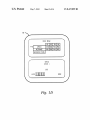
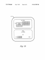
"I50
MAIN MENU /
III 02 03 G4
I58
Z
}
SPEED
90% 902 902 902
=;
RESPONSE
9G2 G02 G02 902
i
PERTGRNANEE ADJUST
01
PGNEREG SEATING
~ DRIVE LOCKOUT
STANDARD PROGRAM
158
!
—
184 L FAULT
JOYSTICK
L06
}
i
I
S162 7 GT INDOOR JOSTYCK AVE ‘66
:
02
RECUNE
CENTER LEGS
{
‘I I88
“LT
MODERATE ouTnooR
D3 SPEED/LEVEL TERRAIN
D4 RAMPS AND EuRGS MOD
\
no
\
‘2
DRIVE
J0
BATTERY LEVEL 24.1
DRIVE CONFIG ENG
NoToR BALANCE
04
ON
SEATING ADJUST
ADVANCED DIAGNOSTICS
182
NAME
U2
GTE MODE
4Sw 4Sw 4Sw 4Sw }
ACTUATOR SELEETIGN --——-—----——>i
SD CARD
CALIBRATIONS
194
D3
OFF OFF GET
G0
lice
io
I;
To
I“
5
SYSTEM
:2
SEATING CONTROL
I:
ICON
j}
‘92
‘l
32 /
I
168
j
MONO PoRT 1
GM
I
MONO PORT 2
MODE
I
VIEW/SCAN
INT TIME
NRM
0
ENG
GET
m OFF
[13 OFF
n3 GEE
n4
I
RRT TIME
0
RM
OFF OFF OFF GEE
;
> LEFT OFF OFF OFF OFF ‘\m,
RIGHT OFF OFF OFF OFF
I
{
ATTENDANT SET
SIPRRGEEGAE
TILT
i
RECLINE
>
LEGS
MOVE UP
SET UP ANGLE
I98
f
0
|
SET IIowN ANGLE 0
I
MOVE IIGNN
Fig. 7A
US. Patent
May 7, 2013
Sheet 13 0f 14
US 8,437,899 B2
156
l
2‘
I
I
I
V
I
I
I
I90
j
:
:
FWD BRAKE
90% D02 902 902
REV SPEED
REV ACCEL
90% 902 907, 9070
902 9070 90% 902
[)3
ASP
i--—> DUAL LEDs
i
REcLlNE
ELEVATE
MAN
MAN
MAN
ASP 10/45 5/90
MAN MAN MAN
ASP MAN MAN
REV BRAKE
TURN SPEED
TURN AEEEL
90% 90% 90% 90%
907° 90% 90% 907°
902 902 902 907.,
I
MAN
MAN
TURN DECEL
D02 90% D02 902
TREMOR DAMP
9oz 90% 90% 902
5
LEGS
MAN
U4
OFF
00 M MD 8.1
90% D02 D02 902
902 902 90% 907.,
D]
0N
TILT
U3
OFF
D1 D2 D3 [14
NAME
FWD SPEED
FWD AECEL
MAN
i
I 166
i
}
If?-i
3i
Z
INDOOR JDSTYCK AVE
POWER LEvEL 90? DD? 90? 90?
MODERATE OUTDOOR
sPEED/LEvEL TERRAIN #\
MIPS
AN“ EUR“ “0°
INDOOR LEARNER
IORDDE
904 90A 90A 904
5“ THROUGH
P
'64 $535555? #5? SE SI‘; 5;;
MOMLATCH
MOM LIEM MDM LTCH
LL!
Em
LAIEM TYPE
CRU IsP BSP ESP
3:
2g
MOM REV
DIBTL 3sPD
ON ON ON OFF
3sP IsP 15F 35F
SLEEP MODE
OFF OFF OFF OFF
STBY SEL
0N OFF OFF OFF
STBY TIME
603 I205 25 20s
STBY IN EDD
0N OFF OFF OFF
I
RIM
ON OFF DEE OFF
§---> STORE In SU-CARU
:
READ FROM SU-[ARD
REMOTE SELECT 0N OFF OFF OFF
ECU 1
OFF MM LTCH COM
.
EED 2
OFF MM LTCH EDM
EEUB
OFF MM LTCH COM
EEU4
OFF MM LTCH EOM
g§‘—'“" STORE To SD'EARU "\
2i
READ FROM SD‘EARD
I
STORE To SMARD q
I
READ FROM SHARE
:
!
‘72
173
\
174
3
N0 DRIVING
OFF OPE OFF ON
i
AUTO SCAN
OFF OFF OFF OFF
:
ICON
I
Fig. 7B
US. Patent
May 7, 2013
Sheet 14 0f 14
US 8,437,899 B2
Display Drive Parameter(s)
for Drive Mode(s)
804
Read Drive
Parameter and
Drive Mode(s)
Adjustment
Selection
806
\
Display Drive Parameter
Adjustment Display fcr
Selected Drive Mode
80
8
Read Drive
Parameter
Adjustment
810 \
Display Drive Parameter
Adjustment for Selected
Drive Mode(s)
812
_\
Save Drive Parameter
Adjustment for Selected
Drive Mode(s)
F. 8
US 8,437,899 B2
1
2
METHOD AND APPARATUS FOR
PROGRAMMING PARAMETERS OF A
POWER DRIVEN WHEELCHAIR FOR A
PLURALITY OF DRIVE SETTINGS
through a hand held programmer unit having an interactive
display and coupled to the control system much as described
in the above-referenced US. Pat. No. 6,819,981 , for example.
Currently, a set of parameters may be programmed into the
control system through the interactive display of the pro gram
CROSS-REFERENCE TO RELATED
APPLICATIONS
mer unit for only one drive setting at a time.
SUMMARY OF THE INVENTION
This application is a continuation of US. Ser. No. 12/064,
697, ?led Feb. 25, 2008, titled METHOD AND APPARATUS
FOR PROGRAMMING PARAMETERS OF A POWER
DRIVEN WHEELCHAIR FORA PLURALITY OF DRIVE
SETTINGS, Which claims priority to International Applica
tion Serial No. PCT/US2006/033963, ?led Aug. 31, 2006,
Which claims the bene?t of eight US. provisional patent
applications, including Ser. No. 60/712,987, ?led Aug. 31,
2005, Ser. No. 60/727,005, ?led Oct. 15, 2005, Ser. No.
60/726,983, ?led Oct. 15, 2005, Ser. No. 60/726,666, ?led
Oct. 15, 2005, Ser. No. 60/726,981, ?led Oct. 15, 2005, Ser.
No. 60/726,993, ?led Oct. 15, 2005, Ser. No. 60/727,249,
?led Oct. 15, 2005, and Ser. No. 60/727,250, ?led Oct. 15,
In accordance With one aspect of the present invention, a
method of pro gramming parameters of a poWer driven Wheel
chair for a plurality of drive modes comprises: displaying a
menu image on an interactive display screen, the menu image
including settings of a plurality of Wheelchair parameters for
20
2005. This application is also related to seven co-pending
U.S. utility patent applications ?led the same day as this
tive to display a menu image on a screen of the display, the
application, including 60/727,005 entitled “Mode Program
mable Actuator Controller for PoWer Positioning Seat or Leg
Support of a Wheelchair,” 60/726,983 entitled “Method and
25
menu image including settings of a plurality of Wheelchair
parameters for a plurality of drive modes of the Wheelchair;
30
and a programming unit operative to control the controller to
select a Wheelchair parameter for a drive mode using the
displayed menu image, and to program the setting of the
selected Wheelchair parameter to a desired setting.
In accordance With yet another aspect of the present inven
Apparatus for Setting or Modifying Programmable Param
eters in PoWer Driven Wheelchair,” 60/726,981 entitled
“Method and Apparatus for Programming Parameters of a
PoWer Driven Wheelchair for a Plurality of Drive Settings,”
60/726,993 entitled “Adjustable Mount for Controller of
PoWer Driven Wheelchair,” 60/ 727,249 entitled “Method and
Apparatus for Automated Positioning of User Support Sur
faces in PoWer Driven Wheelchair,” 60/726,666 entitled
“Context-Sensitive Help for Display Device Associated With
35
a PoWer Driven Wheelchair,” and 60/ 727,250 entitled “PoWer
Driven Wheelchair.” The contents of all above-identi?ed
patent application(s) and patent(s) are fully incorporated
herein by reference.
40
BACKGROUND
The present invention is directed to poWer driven Wheel
chairs, in general, and, more particularly, a method and appa
ratus for programming parameters of a poWer driven Wheel
BRIEF DESCRIPTION OF THE DRAWINGS
50
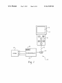
FIG. 1 is a block diagram schematic of an exemplary
embodiment for programming parameter values into a con
trol system of a poWer driven Wheelchair.
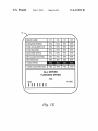
FIG. 1A is an exemplary main menu image for display on
an interactive display screen.
FIG. 1B is one example of a gauge display WindoW for
entitled “Method and Apparatus for Setting Speed/ Response
display on an interactive display screen.
FIG. 1C is another example of a gauge display WindoW for
55
instant application, Which patent being incorporated by ref
parameters Which are programmed into the control system to
satisfy the operational capabilities of the individual user of
the Wheelchair. The programming task is normally conducted
display on an interactive display screen.
FIG. 1D is an example of a display shoWing a menu Win
doW displaying drive parameters for a plurality of drive
modes and a drive parameter adjustment WindoW for a single
drive mode there beloW.
erence herein in its entirety.
Typically, poWer driven Wheelchairs have a plurality of
drive settings for operation of the Wheelchair by the user. An
exemplary Wheelchair may include four drive settings Which
may be Drive 1 (D1) for indoor operation, Drive 2 (D2) for
moderate outdoor operation, Drive 3 (D3) for special opera
tion, and Drive 4 (D4) for ramps and curbs. For each drive
setting, there are numerous performance and poWer seating
menu images on the screen of the display according to a
predetermined routing, to select a Wheelchair parameter for a
drive mode using the displayed menu image, and to program
the setting of the selected Wheelchair parameter to a desired
45
factured by Invacare Corporation of Elyria, Ohio, for
Performance Parameters of a PoWer Driven Wheelchair”,
issued Nov. 16, 2004, and assigned to the same assignee as the
tion, apparatus for programming parameters of a poWer
driven Wheelchair for a plurality of drive modes comprises: a
display; a memory for storing a plurality of menu images,
each menu image including settings of a plurality of Wheel
chair parameters for a plurality of drive modes of the Wheel
chair; a controller for interacting With the memory and dis
play; and a programming unit operative to control the
controller to display a menu image from the plurality of stored
setting.
chair for a plurality of drive settings using a common menu
image of an interactive display screen.
PoWer driven Wheelchairs, Which may be of the type manu
example, are generally controlled by an electronic control
system. An exemplary control system for poWer or motor
driven Wheelchairs is disclosed in US. Pat. No. 6,819,981,
a plurality of drive modes of the Wheelchair; selecting a
Wheelchair parameter for a drive mode from the displayed
menu image; and programming the setting of the selected
Wheelchair parameter to a desired setting.
In accordance With another aspect of the present invention,
apparatus for programming parameters of a poWer driven
Wheelchair for a plurality of drive modes comprises: a dis
play; a controller for interacting With the display and opera
60
FIG. 1E is an example of a display shoWing a menu WindoW
displaying drive parameters for a plurality of drive modes and
a drive parameter adjustment WindoW for a all drive modes
there beloW.
FIG. 1F is an example of a display shoWing a portion of a
65
performance adjust WindoW displaying drive parameters for a
plurality of drive modes and drive parameter adjustment Win
doW for a single drive mode there beloW.
US 8,437,899 B2
4
3
may access the preset parameters and relationships stored in
the EEPROM 32 and store them temporarily to the scratch
pad memory 28 for interaction with the remote programmer
unit 14 and operation of the wheelchair. It is understood that
when power is removed, the stored data of the RAM 28 will be
lost. Only, the EEPROM 32 will retain the data of its memory
without power.
As indicated above, the microcontroller 20 of the power
wheelchair is programmed to interact with the remote pro
grammer unit 14 via signal lines 22 and communication con
troller 24, if used, for entry of the parameter values or settings
and for the display thereof. The ?owcharts of FIGS. 2 through
6 exemplify programs for execution by the microcontroller 20
for performing the aforementioned tasks. In describing the
various ?owcharts herein below, the term block will be used
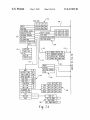
FIG. 1G is an example of a display showing a portion of a
performance adjust window displaying drive parameters for a
plurality of drive modes and drive parameter adjustment win
dow for all drive modes there below.
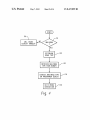
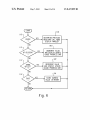
FIGS. 2 through 6 are ?owcharts which exemplify pro
grams for execution by a controller for programming param
eter values of different drive modes for the control system of
the wheelchair.
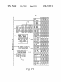
FIGS. 7A and 7B compositely depict a ?owchart exempli
fying menu images for display on an interactive display
screen and predetermined navigational routings between
menu images. FIGS. 7A and 7B will hereinafter be collec
tively referred to as FIG. 7.
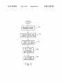
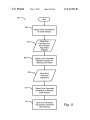
FIG. 8 is an example ?owchart of a procedure for display
ing one or more drive parameters for one or more drive modes
and for adjusting one or more drive parameters for one or
more drive modes.
to refer to a step or steps for performing a function or task by
the controller 20.
DETAILED DESCRIPTION
20
The block diagram schematic of FIG. 1 illustrates suitable
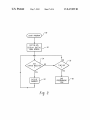
task program or parameter setting mode. In the next block 52,
the microcontroller 20 initialiZes the program settings of the
parameter setting mode, and then, transmits via lines 22 an
apparatus for embodying the principles of applicants’ general
concept. Referring to FIG. 1, a remote, hand held program
mer unit 14 may be coupled to a control system 10 of the
power driven wheelchair and comprises a display screen 16
25
which may be a liquid crystal display (LCD), for example,
An exemplary initial or main menu image screen display in
a table format is shown in FIG. 1A. In the present embodi
tings, like Speed and Response values, for example, by inter
30
better understood from the description below. More speci?
cally, the pushbuttons 18 may include a Power I/O (P), Save
(Sa), Enter (E), left arrow, right arrow, up arrow and down
arrow pushbuttons.
In the present exemplary embodiment, the remote pro
35
grammer unit 14 communicates with a main controller 20 of
the control system 10 via serially coded signals over lines 22.
The main controller 20 may include a programmed micro
controller, which may be of the type manufactured by In?n
eon, bearing model no. SAF-XC-l64CS, for example. The
serial lines 22 may be coupled to the microcontroller 20
through a serial communication controller (SCC) 24 which
may be of the type licensed by Echelon Corporation and
manufactured by Toshiba bearing model no. TMPN3150, for
example. The tasks of the Echelon controller 24 include set
initial screen of a main menu image to the programmer unit 14
for display on the LCD screen 16 thereof. The display screen
16 of the programmer unit 14 may be a graphics LCD screen
having 160x160 pixels for display, for example.
and a plurality of pushbuttons 18 for use in selecting the
desired drive and parameter and entering the parameter set
acting with the image on the display screen 16 as will become
Referring to FIG. 2, in block 50, the microcontroller 20
responds to the activation (depression) of the P pushbutton of
the remote programmer unit 14 by entering the programming
ment, the main menu screen image is a table with three rows.
The top row of the three includes the parameter word “Speed”
in the left most column followed by four columns of the preset
parameter values thereof for the drives D1-D4 and the next
row down includes the parameter word “Response” in the left
most column followed the four columns of the preset param
eter values thereof for the drives D1-D4, all of the parameter
values being accessed from the EEPROM 32 as described
herein above. Note that the Speed and Response parameters
may be programmed for all of the drives: D1, D2, D3 and D4
40
which are displayed in the table format of the main menu
screen image. The bottom row of the table may include the
text “Advanced Menu” to permit access to a selection menu
screen for selection of additional menu screen images for
45
more parameter settings, or, in the alternative, additional rows
of the table may be displayed for the direct selection of the
ting the protocol, performing serial/parallel translations,
additional menu screen images as will become better under
checking for errors in transmission, and managing the tra?ic
stood from the description of FIG. 7 infra.
The selection of each row of text may be performed by the
for the serial communication between the remote program
mer unit 14 and microcontroller 20. In the alternative, the
tasks of the serial communication controller 24 may be pro
grammed into the main controller 20, in which case, the serial
lines 22 may be coupled directly to the main controller 20 and
the SCC may be eliminated. Moreover, while the communi
cation link between the programmer unit 14 and controller 20
of the exemplary embodiment is over lines 22, it may just as
movement of a pointer, e. g. an arrow pointer shown to the left
50
of the image (shown to the left of “Speed” in FIG. 1A) or by
highlighting the text in some manner or both. Each row posi
55
tion of the pointer is correlated in the microcontroller pro
gram with a number. For example, the number 0 may repre
sent the ?rst row or Speed pointer position, the number 1 may
represent the second row or Response pointer position, and
well be a wireless communication link, like a BLUETOOTH
the number 2 may represent the third row or Advanced Menu
link or a 802.1 1 link, for example, without deviating from the
pointer position. If the pointer was set to 0 in block 52, for
example, a pointer image may appear adjacent to the text
broad principles of applicants’ general concept.
The microcontroller 20 may include an internal memory 28
which may be of the random access (RAM) or scratch pad
“SPEED” in row 1 as shown in FIG. 1A, or the text “SPEED”
60
type, for example, and is coupled to an electrically erasable
programmable read only memory (EEPROM) 32 over
address (A), data (D) and control (C) lines. While the memory
28 is shown internal to the microcontroller 20, it is understood
that a portion or all of the memory 28 may be just as well
external to the microcontroller 20. Generally, when powered
up, the controller 20 will boot up under program control and
may be highlighted.
In the present exemplary embodiment, the programmer
unit 14 will send a key status signal via lines 22 to the micro
controller 20 every ten (10) milliseconds. Each key status
signal will indicate to the program if a pushbutton has been
65
depressed and a code representative of the depressed push
button. The program will detect the reception of a key status
signal in block 54. If the controller 20 does not receive a key