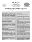
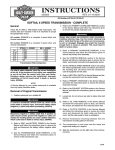
1
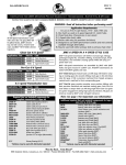
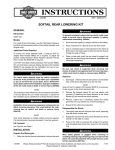
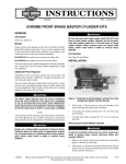
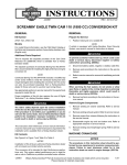
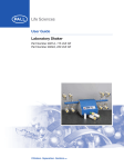
INSTRUCTIONS
®
REV. 10-13-2005
-J03260
Kit Numbers 33034-03A, 33040-03A
DYNA 6 SPEED TRANSMISSION - COMPLETE
General
These kits fit 2001 to 2005 FXD model motorcycles.
Requires separate purchase of cable Sidecover Release Kit
or Hydraulic Sidecover Release Kit. See retail catalog for
parts numbers. Refer to Instructions included in Sidecover
Release Kits to complete installation of Screamin’ Eagle 6Speed Transmission or Gearset Kits.
Kit 33034-03A is a complete 6 Speed Silver and Chrome
transmission.
Kit 33040-03A is a complete 6 Speed Black and Chrome
transmission.
1st
2 nd
3 rd
4 th
5 th
6 th
STOCK 5 - SPEED
3.210
2.209
1.572
1.226
1.000
NA
SE 6 - SPEED
3.210
2.209
1.572
1.226
1.000
0.885
Transmission Ratio Comparison
1WARNING
The rider's safety depends upon the correct installation
of this kit. If the procedure is not within your capabilities
or you do not have the correct tools, have your HarleyDavidson dealer perform the installation. Improper
installation of this kit could result in death or serious
injury. (00308a)
NOTE
A Service Manual for your model motorcycle is available
from any Harley-Davidson dealer.
Removal of Original Transmission
1. Position motorcycle on a suitable lift.
1WARNING
To prevent accidental vehicle start-up, which could
cause death or serious injury, disconnect battery cables
(negative (-) cable first) before proceeding. (00307a)
1WARNING
Disconnect negative (-) battery cable first. If positive (+)
cable should contact ground with negative (-) cable connected, the resulting sparks can cause a battery explosion,
which could result in death or serious injury. (00049a)
2. Refer to the Service Manual and follow the instructions
given to remove the seat and disconnect the battery
cables, negative cable first.
3. Refer to the TRANSMISSION CASE REMOVAL in the
Service Manual and follow the instructions given to
remove the components with the following steps.
4. Refer to REMOVING ENGINE FROM THE CHASSIS in
the Service Manual and follow the instructions given for
the removal of the transmission with the following exceptions:
a. The air cleaner, fuel tank and carburetor need not be
removed.
b. The spark plugs do not need to be removed.
c. Stabilizer link nut and horn bracket bolts do not need
to be removed.
d. MAP sensor does not have to be removed.
e. The front downtubes do not need to be protected.
f. A ratchet strap is not needed to secure the transmission.
5 Refer to the CLUTCH CONTROL in the Service Manual
and follow the instructions given to remove the clutch
cover and disconnect the clutch cable end from the
cover and set the cable aside.
NOTE
Be sure to remove the inspection cover’s top and rear
screws or the inspection cover, primary chaincase cover and
the inner primary chaincase housing will be damaged.
6. Refer to PRIMARY CHAINCASE REMOVAL in the
Service Manual and follow the instructions given to
remove the primary chaincase cover.
1WARNING
Wear safety glasses or goggles when removing or
installing retaining rings. Retaining rings can slip from
the pliers and could be propelled with enough force to
cause serious eye injury. (00312a)
7. Refer to the PRIMARY CHAINCASE HOUSING in the
Service Manual and follow the instructions given to
remove the primary chaincase housing.
8. Refer to the REAR WHEEL REMOVAL in the Service
Manual and follow the instructions given to remove the
belt.
a. Remove the belt guard and debris deflector.
b. Remove spring clip.
c. Loosen axle nut enough to slide wheel forward.
d. Note the rear wheel does not need to be removed.
e. Remove the belt and set aside.
1 of 6
9. See the VEHICLE SPEED SENSOR section and
unplug the vehicle speedometer sensor connection and
remove the mounting bolt. Lift sensor from the transmission case and set aside.
5. Slide fork assembly into position aligning with mounting
boss of transmission case. Install pivot shaft removed
with attached nut. Install washer and screw. Tighten
screw to 45-50 ft-lbs (61.0-67.8 Nm).
10. Refer to NEUTRAL SWITCH and disconnect the connectors from the neutral switch.
6. Install the two screws, washer and nuts to the rubber
isolator mounting assembly at the rear lower boss of
the transmission. Tighten to 18-22 ft-lbs (24.4-29.8
Nm).
11. Refer to the STARTER REMOVAL in the Service
Manual and follow the instructions given to remove the
the starter.
12 Position a jack with a wooden block under the engine
and transmission oil pan.
13. Refer to the ENGINE MOUNTS in the Service Manual
and follow the instructions given to remove the transmission from the rear isolator.
14. Refer to the REAR FORK REMOVAL in the Service
Manual and follow the instructions given to remove the
plug, screw and lockwasher from the rear fork. Remove
the screw and lockwasher and slide the pivot shaft with
the attached nut out the right side.
15. Remove the four bolts and washers connecting the
engine to the transmission.
16. The transmission is now loose from the frame and
engine and resting on a support.
7. Install the two socket head screws, lockwashers and
washer through the rear frame transmission mounting
holes. Tighten to 22-27 ft-lbs (29.8-36.6 Nm).
8. Install belt over rear wheel sprocket and transmission
sprocket. Refer to REAR BELT DEFLECTION in the
Service Manual and follow the instructions given to correctly install the belt to the proper deflection.
9. Refer to the PRIMARY CHAINCASE HOUSING in the
Service Manual and follow the instructions given to
install the chaincase housing.
10. Refer to NEUTRAL SWITCH in the Service Manual and follow the instructions giver to install these connections.
11. Refer to VEHICLE SPEED SENSOR in the Service
Manual and follow the instruction given to install the
speedometer speed sensor and use the new o-ring (85)
provided in the kit.
17. Slide the transmission toward the rear of the bike (to clear
the dowel pins) and lift the transmission out the right side.
12. Refer to the STARTER INSTALLATION in the Service
Manual and follow instructions given to install starter
from the right side.
Installation of New Transmission
13. Refer to the DRIVE COMPONENTS in the Service
Manual and follow the instruction given to install the
clutch assembly, primary chain and compensating
sprocket as a single assembly.
1. Refer to your Service Manual and follow the instructions
given to install the new transmission into the motorcycle.
2. Slide the transmission from the right and align the four bolt
holes on the transmission with the four holes on the engine.
3. Install the four bolts and washers removed in step 15.
4. See Figure 1. Tighten the four transmission mounting
bolts in a cross pattern sequence as follows:
a.First tighten all four in turn to 15 ft-lbs (20.3 Nm).
b.Then tighten all four in turn to 30-35 ft-lbs (40.7-47.5
Nm).
14. Install the side cover.
For Cable Actuated Clutch: Follow the instructions in
the SE 6-Speed Cable Clutch Side Cover and Release
Pushrod Kit (Part Number 38752-04).
For Hydraulic Clutch: Follow the instructions in the
Hydraulic Clutch Side Cover and Release Pushrod Kit
(Part Number 38753-04), and in the Hydraulic Clutch
Kit (Part Number 45033-03, Black or 45383-03,
Chrome).
i06178
4
2
3
1
Dowel pins
Figure 1. Transmission to Crankcase Torque Sequence
Transmission viewed from front
-J03260
2 of 6
®
Part No. 33034-03A
Service Parts
Date 08/04
6 Speed Transmission -Silver and Chrome
i06777
66
70
67
12
19 20
21
22
49
5
14
10 4
6
8
7
24 25
61
46 64
1
2
37
9
8 3
14
47
8282
83
21
38 19 20
42
31
11
65
22
24 25 24
82
10 4
43
82 82
24
43
45
15
5556 57
24
43
77 80
78 81
79
85
17 16 18
63 28
43
51 52
26
53
27
72 71
32
7636 29
44
84
53
59
23
40 58 41
62
35
68
48
69
33
48 73
39
30
49
49
60
34 50
54
49
49
75
Item
1
2
3
4
5
6
7
8
9
10
11
12
13
14
15
Description (Qty)
Mainshaft
Countershaft
Countershaft 1st Gear
Mainshaft 3rd Gear/
Countershaft 2nd Gear (2)
Mainshaft 4th Gear
Mainshaft 6th Gear
Mainshaft 1st Gear
Countershaft 3rd Gear/
Mainshaft 2nd Gear (2)
Countershaft 4th Gear
Shift Ring, 1-2, 3-4 (2)
Shift Ring, 5-6
Chrome Trapdoor with Ear
Oil Pan with Baffle, Plain
Sleeve Spline (2)
Shifter Fork Shaft
-J03260
Part No.
35058-03
35059-03
35080-03
35083-03
35104-03
35131-03
35134-03
35135-03
35136-03
35137-03
35138-03
35139-0313
26085-99A
35140-03
34088-87A
Item
16
17
18
19
20
21
22
23
24
25
26
27
28
29
30
69
13
74
Description (Qty)
Shifter Fork, 1-2 Assembly
Shifter Fork, 3-4 Assembly
Shifter Fork, 5-6 Assembly
Door Retaining Ring (2)
Trap Door Bearing (2)
Mainshaft/Countershaft
Locknut (2)
Clutch Release Cover
Lower Screw (4)
Shifter Lever Screw
Pushrod Thrust Washer
Mainshaft Thrust Washer (2)
Sprocket Spacer
Mainshaft Race
Main Case Seal
Quad Seal
Vent Top Lid Fitting
Part No.
35143-03
35144-03
35145-03
35087-99
8992A
35078-79
4718A
856A
37313-80
6003
33344-94
34091-85A
12067B
11165
62375-57A
3 of 6
®
Item
31
32
33
34
35
36
37
38
39
40
41
42
43
44
45
46
47
48
49
50
51
52
53
54
55
56
57
58
Service Parts
Description (Qty)
Mainshaft 5th Gear
Speedo Sensor Plate Screw
Neutral Switch
Chrome Lid Top
Oil Pan Gasket
Countershaft Bearing
Trap Door Gasket
Clutch Release Cover Gasket
Lid Gasket
Shifter Shaft Seal
Shifter Shaft Retaining Ring
Trap Door Screw, Upper
Pillow Block Screw (4)
Shifter Centering Screw
Chrome Dipstick
Dipstick O-Ring
Countershaft Gear, 5th
Top Lid Screw (2)
Clutch Release Cover Screw
Upper (6)
Top Lid Screw
Transmission Pulley
Mega Nut
Mega Nut Screw (2)
Oil Pan Screw (10)
Shift Drum Assembly
Shifter Shaft Assembly
Shift Drum Retainer
Shifter Seal Washer
-J03260
Part No.
35237-03
4705
33904-00A
34469-01
26072-99A
8977
35147-03
35148-03
34917-99B
12045
11150
4814A
3909
34978-00A
37075-87
11132
35238-03
4740A
4717A
4822A
40250-94C
35236-03
4069A
4741A
35142-03
35146-03
11342
6497HW
Part No. 33034-03A
Date 08/04
6 Speed Transmission - Silver
Item
59
60
61
62
63
64
65
66
67
68
69
70
71
72
73
74
75
76
77
78
79
80
81
82
83
84
85
Description (Qty)
Shifter Lever
Clear Dip Stick
Plug for Door
Door Roll Pin
Main Case Bearing
Harness Door Retaining Clip
Trap Door Screw, Lower (3)
Top Door Stud
Bottom Door Stud
Motor Oil Hose (2)
Hose Clamp (Black) (3)
Speedo Sensor O-Ring
Sensor Plate Gasket
Sensor Plate
Transmission Top Cover Vent Hose
Elbow Motor Vent Fitting
Top Cover Vent Motor Hose
Case Bearing Retaining Ring
Right Pillow Block
Detent Spring (Right Pillow Block)
Follower Detent (Right Pillow Block)
Detent Arm Spring
(Right Pillow Block)
Detent Arm Screw
(Left Pillow Block)
Cage Bearing Split (5)
Shifter Shaft Set Screw
Shifter Shaft Assembly
Transmission Case Sub-Assembly
(Silver) (2001 and Up FXD
Part No.
33849-97
62853-99
45853-99
634
8996A
38709-99
3249
16709-95
16708-95
62726-99
10249
11289A
35152-03
35153-03
42533-91A
16334-02
45795-02
11161
33304-00
33375-00A
33364-00A
33374-00
33376-00
8876A
3784
35146-03
34791-03
4 of 6
®
Service Parts
Part No. 33040-03A
Date 08/04
6 Speed Transmission - Black and Chome
i06778
85
66
67
12
5
19 20
21
13
10 4
8
7
6
24 25 24
25
24
31
11
1
22
61
49
47 64
39
21
19 20
43
44
55 56 57
18
18 18
70
22
44
77
2
65
24
9
38
8
13
3
10 4
46
14
16 15
44
79
80
81
82
83
44
24 24 24 18 18
17
84
63
28
26
51 52
53
27
71 72
32
76 33
45
29
53
59
23
78
41 58 42
36
62
34
48
73
48
69
68
30
40
49
49
35
60
50
49
54
75
Item
1
2
3
4
5
6
7
8
9
10
11
12
13
14
15
Description (Qty)
Mainshaft
Countershaft
Countershaft 1st Gear
Mainshaft 3rd Gear/
Countershaft 2nd Gear (2)
Mainshaft 4th Gear
Mainshaft 6th Gear
Mainshaft 1st Gear
Countershaft 3rd Gear/
Mainshaft 2nd Gear (2)
Countershaft 4th Gear
Shift Ring, 1-2, 3-4 (2)
Shift Ring, 5-6
Chrome Trapdoor with Ear
Sleeve Spline (2)
Shifter Fork Shaft
Shifter Fork, 1-2 Assembly
-J03260
Part No.
35058-03
35059-03
35080-03
35083-03
35104-03
35131-03
35134-03
35135-03
35136-03
35137-03
35138-03
35139-0313
35140-03
34088-87A
35143-03
Item
16
17
18
19
20
21
22
23
24
25
26
27
28
29
30
69
37
74
Description (Qty)
Shifter Fork, 3-4 Assembly
Shifter Fork, 5-6 Assembly
Cage Bearing Split (5)
Door Retaining Ring (2)
Trap Door Bearing (2)
Mainshaft/Countershaft
Locknut (2)
Clutch Release Cover
Lower Screw (4)
Shifter Lever Screw
Mainshaft/Countershaft
Retaining Ring (8)
Mainshaft Thrust Washer (2)
Sprocket Spacer
Mainshaft Race
Main Case Seal
Quad Seal
Vent Top Lid Fitting
Part No.
35144-03
35145-03
8876A
35087-99
8992A
35078-79
4718A
856A
11067
6003
33344-94
34091-85A
12067B
11165
62375-57A
5 of 6
®
Item
31
32
33
34
35
36
37
38
39
40
41
42
43
44
45
46
47
48
49
50
51
52
53
54
55
56
56
57
58
Service Parts
Description (Qty)
Mainshaft 5th Gear
Speedo Sensor Plate Screw
Case Bearing Retaining Ring
Neutral Switch
Chrome Lid Top
Oil Pan Gasket
Oil Pan (with Black Baffle)
Trap Door Gasket
Clutch Release Cover Gasket
Lid Gasket
Shifter Shaft Seal
Shifter Shaft Retaining Ring
Trap Door Screw, Upper
Pillow Block Screw (4)
Shifter Centering Screw
Chrome Dipstick
Dipstick O-Ring
Top Lid Screw (2)
Clutch Release Cover Screw
Upper (6)
Top Lid Screw
Transmission Pulley
Mega Nut
Mega Nut Screw (2)
Oil Pan Screw (10)
Shift Drum Assembly
Left Pillow Block
Shifter Shaft Assembly
Shift Drum Retainer
Shifter Seal Washer
-J03260
Part No.
35237-03
4705
11161
33904-00A
34469-01
26072-99A
26087-99A
35147-03
35148-03
34917-99B
12045
11150
4814A
3909
34978-00A
37075-87
11132
4740A
4717A
4822A
40250-94C
35236-03
4069A
4741A
35142-03
33301-00A
35146-03
11342
6497HW
Part No. 33040-03A
Date 08/04
6 Speed Transmission - Black and Chome
Item
59
60
61
62
63
64
65
66
67
68
69
70
70
71
72
73
74
75
76
77
78
79
80
81
82
83
84
85
Description (Qty)
Shifter Lever
Clear Dip Stick
Shifter Shaft Set Screw
Door Roll Pin
Main Case Bearing
Harness Door Retaining Clip
Trap Door Screw, Lower (3)
Top Door Stud
Bottom Door Stud
Motor Oil Hose (2)
Hose Clamp (Black) (3)
Drain Plug
Speedo Sensor O-Ring
Sensor Plate
Sensor Plate Gasket
Transmission Top Cover Vent Hose
Elbow Motor Vent Fitting
Top Cover Vent Motor Hose
Countershaft Bearing
Countershaft Gear, 5th
Shifter Shaft Assembly
Right Pillow Block
Detent Arm Screw
Detent Sleeve
Detent Follower
Detent Arm Spring
Transmission Sub-Assemby Case,
(Black, 2001 and UP FXD)
Speedo Sensor O-Ring
Part No.
33849-97
62853-99
3784
634
8996A
38709-99
3249
16709-95
16708-95
62726-99
10249
45830-48
11289A
35153-03
35152-03
42533-91A
16334-02
45795-02
8977
35238-03
35146-03
33304-00
33376-00
33375-00A
33364-00A
33374-00
34795-03
11289A
6 of 6