1
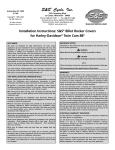
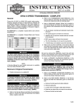
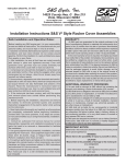
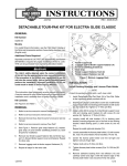
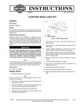
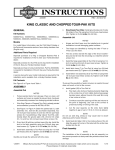
-J05918
REV. 2015-04-17
TRIKE PASSENGER ARMREST KIT
GENERAL
INSTALLATION
Kit Number
1.
52400106
2014-later models: See the service manual. Remove the
Tour-Pak and mounting bracket assembly as a unit. Set
aside for installation. Save the nuts
Models
For model fitment information, see the P&A retail catalog or
the Parts and Accessories section of www.harley-davidson.com
(English only).
Installation Requirements
2008-2013 models: See the service manual. Remove the
Tour-Pak®. Set aside for installation. Discard the screws.
Drill Armrest Support Mounting Holes
2.
Both Loctite® 243 Medium Strength Threadlocker and Sealant
- Blue (Part No. 99642-97) and Loctite 262 Threadlocker and
Sealant - Red (Part No. 94759-99) are required for proper
installation of this kit.
Electrical Contact Lube (H-D Part No. 11300004) or equivalent
is required for proper installation of this kit.
ALL models: See Figure 3. Get the armrest support
drilling template (19) from the kit. Cut out the template
along the black outline (A). See Figure 1. Place the template on the top front of the vehicle body, aligning with
body contours.
a.
See Figure 3. Align the template centerline (B) with
the seat mounting screw threaded hole.
b.
Align the template forward edges (C) along the body
downward curves.
c.
Align the template sides (D) between the body upward
curves.
These items are available from a Harley-Davidson dealer.
The rider's safety depends upon the correct installation
of this kit. Use the appropriate service manual procedures.
If the procedure is not within your capabilities or you do
not have the correct tools, have a Harley-Davidson dealer
perform the installation. Improper installation of this kit
could result in death or serious injury. (00333a)
is08579
NOTE
This instruction sheet refers to service manual information. A
service manual for this year/model motorcycle is required for
this installation. One is available from a Harley-Davidson dealer.
Kit Contents
See Figure 3 and Table 1.
PREPARATION
To prevent accidental vehicle start-up, which could cause
death or serious injury, remove main fuse before proceeding. (00251b)
NOTE
•
•
WITH security siren: With security fob present, turn
ignition switch ON. See the service manual. Disarm
security system. Turn ignition switch OFF. IMMEDIATELY
remove the main fuse.
WITHOUT security siren: See the service manual.
Remove main fuse.
-J05918
Figure 1. Armrest Support Drilling Template
3.
Tape the template to the body to hold in place.
4.
Drill eight pilot holes at the indicated locations (E). Enlarge
the holes with a 9/32 in (K) (7.2 mm) stepped drill bit.
5.
Remove the template.
Many Harley-Davidson® Parts & Accessories are made of plastics and metals which can be recycled.
Please dispose of materials responsibly.
1 of 4
2014-Later models: Remove the Tour-Pak from the
mounting bracket. Remove the ground plate from inside
the Tour-Pak bottom.
Install Armrest Support Blocks
NOTE
Support block installation requires rear wheel and tire removal.
6.
Remove rear wheel and tire. See service manual.
7.
See Figure 3. Assemble an armrest support block (13)
and pad (14). Place the assembly onto the vehicle body
with the two side holes facing the vehicle center. Align the
four mounting holes.
a.
Turn the ground plate over, above a work surface with
the stud threads facing upward.
b.
Get a socket large enough to fit over the stud heads.
Place the socket on the work surface.
c.
Rest the ground plate on the socket so one stud head
is inside the socket opening.
d.
Lightly tap the screw end with a hammer to remove
the stud. Discard the stud.
8.
Get an armrest support plate (15), two short screws (16),
two long screws (18) and four split lockwashers (17) from
the kit. Slide a lockwasher onto the threads of each screw.
9.
Apply a few drops of Loctite 262 - Red to the clean screw
threads.
e.
Turn the ground plate right side up. Set the ground
plate inside the Tour-Pak. Align the holes.
10. See Figure 2. Place the armrest support plate (3) on the
underside of the body in the orientation shown, aligning
the holes.
f.
See Figure 3. Place two armrest support adapter
plates (11) on the Tour-Pak mounting rack. Align the
four holes.
11. Using the longer screws (4) at the rear, fasten the armrest
support block (1), pad (2) and plate (3) to the body. Tighten
to 120 in-lbs (13.6 N-m).
g.
Get four long button head cap screws (12) from the
kit. Insert the screws through the ground plate, TourPak bottom and armrest support adapter plates.
Thread the screws into the nuts on the underside of
the Tour-Pak mounting bracket.
h.
Tighten the screws to 120 in-lbs (13.6 N-m).
i.
Set the Tour-Pak and mounting bracket assembly
onto the vehicle body. Align the studs into the holes.
Fasten with four nuts removed earlier. Tighten to 120
in-lbs (13.6 N-m).
Repeat for the remaining studs.
12. Install rear wheel and tire. See service manual.
13. Repeat steps 6-12 on the opposite side.
is08580
1
2
Install Armrest Assemblies
NOTE
3
The armrest assemblies are side-specific. The left knuckle bar
(F) is marked "L", the right bar is marked "R".
6
4
1.
2.
3.
4.
5.
6.
5
Armrest support block
Armrest support pad
Armrest support plate
Longer screw (2)
Shorter screw (2)
Lock washer (4)
Figure 2. Armrest Support Block Installation
Install Tour-Pak
14. Get the Tour-Pak set aside earlier.
2008-2013 models: Get four long button head cap screws
(12) from the kit.
a.
Set the Tour-Pak onto the Tour-Pak mounting bracket.
Align the holes.
b.
Insert the screws through the ground plate and TourPak bottom. Thread the screws into the nuts on the
underside of the Tour-Pak mounting bracket.
c.
-J05918
15. Get one armrest assembly (Item 1 or 2) and two screws
(18) from the kit. Apply Electrical Contact Lube (Part No.
11300004) to the armrest knuckle bar (F) before installation.
16. Slide the knuckle bar into the correct-side support (13)
until the holes align.
Apply a few drops of Loctite 243 - Blue to the clean screw
threads. Insert the screws. Tighten to 144 in-lbs (16.3 Nm).
NOTE
The armrest pads are side-specific. The underside of the pad
is marked "L" (left) or "R" (right). In addition, the left armrest
pad (7) has an operation label (8) under the lid.
17. Get the correct armrest pad (Item 6 or 7) from the kit. Apply
Electrical Contact Lube to the linear bearing (H) before
installation.
18. Install the pad assembly by carefully pushing the pin on
the underside into the armrest. A slight back-and-forth
rotation of the pad helps get the bearing surface into the
armrest receptacle.
19. Repeat Steps 15-18 for the remaining armrest.
Tighten the screws to 120 in-lbs (13.6 N-m).
2 of 4
Check armrest torque (rotational resistance) every service
interval. Tighten bolts (5) to 20 ft-lbs (27 Nm). Then, while
holding bolt, tighten each nut to 20 ft-lbs (27 Nm).
COMPLETION
NOTE
To prevent possible damage to the sound system, verify that
the ignition switch is OFF before installing the main fuse.
1.
A service hardware kit (G) is available if adequate resistance
cannot be achieved due to normal wear of rotating parts. When
installing, apply Loctite 262 (red) to only the threads of the
shoulder bolt. Apply electrical contact lube (Part No. 11300004)
to the bolt shaft and other rotating contact surfaces. Tighten
bolt to 20 ft-lbs (27 Nm). Then, while holding bolt, tighten each
nut to 20 ft-lbs (27 Nm).
See the owner's manual. Install main fuse.
IN USE
IMPORTANT: After 50 mi (80 km) of travel, tighten rear
wheel lug nuts per the service manual.
If arms are loose after being tightened to torque specification,
disassemble and realign disc spring support structure bushing
and top hat. When properly installed, arms show some resistance when rotated around shoulder screw.
Passenger mounting and dismounting: See label inside left
armrest pad.
To minimize wear of armrest pads or backrest covering, rotate
pad so nose faces straight outward or inward. Rotate arm
outward.
The pad assembly will loosen over time through normal use.
A replacement linear bearing (H) and an O-ring service kit (I)
are available from a Harley-Davidson dealer.
DO NOT press down on armrest when mounting or dismounting
vehicle.
SERVICE PARTS
is08569
A
D
8
7
E
19
C
E
H
B
D
3
C
12
I
9
4
13
5
18
G
2
11
6
18
10
F
9
17
13
18
G
16
I
14
H
15
1
17
16
18
10
3
4
5 G
Figure 3. Service Parts, Trike Passenger Armrest Kit
-J05918
3 of 4
SERVICE PARTS
Table 1. Service Parts
Item
Description (Quantity)
Part Number
1
Passenger armrest assembly (right). Includes items 3-5)
52400108
2
Passenger armrest assembly (left). Includes items 3-5)
52400109
3
•
Bushing
11000087
4
•
Cap screw, hex head
9468
5
•
Flanged locknut
7601
6
Passenger armrest pad (right)
52400133
7
Passenger armrest pad (left). Includes Item 8.
52400134
8
•
Not sold separately
9
Knuckle cover, passenger armrest (2)
Not sold separately
10
Nut cap (2)
Not sold separately
11
Adapter plate, armrest support (2 included in spacer kit 53000461)
Not sold separately
12
Screw, hex socket button head, 1/4-20 x 1-1/2 in (38 mm) long (4)
3088
13
Support block, armrest (2)
52400107
14
Pad, armrest support block (2)
52400117
15
Plate, armrest support (2)
52400113
16
Screw, hex socket button head, 1/4-20 x 3/4 in (19 mm) long (4)
4069A
17
Lockwasher, split, 1/4 in (8)
7036
18
Screw, hex socket button head, 1/4-20 x one in (25.4 mm) long (8)
852A
19
Template, armrest support drilling
52400120
Label, armrest operation
Items referenced in text, but not included in kit:
A
Template outline
B
Template centerline
C
Template forward edge
D
Template side
E
Pilot hole location (8)
F
Armrest knuckle bar (2)
G
Service Hardware Kit. Part No. 91800061.
H
Linear bearing (2). Part No. 12600089.
I
O-ring Service Kit (contains four O-rings). Part No. 11900099.
-J05918
4 of 4